JP3758607B2 - Shelf board mounting device - Google Patents
Shelf board mounting device Download PDFInfo
- Publication number
- JP3758607B2 JP3758607B2 JP2002174091A JP2002174091A JP3758607B2 JP 3758607 B2 JP3758607 B2 JP 3758607B2 JP 2002174091 A JP2002174091 A JP 2002174091A JP 2002174091 A JP2002174091 A JP 2002174091A JP 3758607 B2 JP3758607 B2 JP 3758607B2
- Authority
- JP
- Japan
- Prior art keywords
- plate
- shelf
- piece
- mounting
- bracket
- Prior art date
- Legal status (The legal status is an assumption and is not a legal conclusion. Google has not performed a legal analysis and makes no representation as to the accuracy of the status listed.)
- Expired - Fee Related
Links
Images


Description
【0001】
【発明の属する技術分野】
本発明は、棚板の取付装置に係わり、更に詳しくはブラケットを介して支柱に棚板を取付けるための棚板の取付装置に関するものである。
【0002】
【従来の技術】
従来、棚装置において、両側に立設した支柱にブラケットを取付け、両ブラケットにて棚板を載支する構造は極めて一般的である。
【0003】
この場合、前記ブラケットの下端には棚板の側縁部を載支する受板を内方へ形成し、更に棚板の前後の移動を規制するために、棚板の前縁部とその後方に横設した補強部材間に嵌合する規制板を前記受板の内端に立設した構造も公知である。
【0004】
しかし、前述の構造では、棚板を持ち上げればブラケットから簡単に外れてしまい、また地震等の振動によって棚板が不意に落下することも想定される。そこで、従来は棚板をブラケットにネジ止めするなどの固定手段をさらに付加していたのである。ところが、このようにネジ止め等の固定手段を採用した場合には、棚板の取付作業に手間がかかるとともに、コスト高となる傾向がある。
【0005】
【発明が解決しようとする課題】
本発明が前述の状況に鑑み、解決しようとするところは、両側に立設した支柱にブラケットを取付け、両ブラケットにて棚板を支持する構造において、棚板の取付作業が極めて簡単であるとともに、ネジ止め等の固定手段を一切使用せずに、単に嵌合のみで前後左右の移動が規制され、更には上方への外れ防止もなされる安価な棚板の取付装置を提供する点にある。
【0006】
【課題を解決するための手段】
本発明は、前述の課題解決のために、両側に立設した支柱にブラケットを取付け、両ブラケットにて棚板を支持する棚板の取付装置であって、前記棚板は、載置板の前縁に下方へ前面板を形成するとともに、該前面板の下端から後方へ下板を形成し、更に該下板の後端から立起片を立ち上げ形成し、また前記載置板の両側縁から下方へ側面板を形成するとともに、該側面板の下端から内方へ載支片を形成して断面略L字形となし、更に前記載置板の下面で前後中間部に断面略コ字形の補強部材を横設し、該補強部材の前面側の垂直面の両端部に縦長のスリット孔を形成し、前記ブラケットは、基板の下端に前記棚板の載支片を載置する受板を内向きに形成するとともに、該受板の前部内側端に前記立起片と垂直面の間隔に略等しい長さの規制板を立ち上げ形成し、更に前記規制板の後端には、前記垂直面のスリット孔に嵌入する爪片を後向きに突設するとともに、前記規制板の前端には下部に前記立起片に当接する当接部を形成し且つ上部に該当接部よりも前方へ突出した規制部を形成してなる棚板の取付装置を構成した。
【0007】
ここで、前記補強部材の前面側の垂直面は、前記立起片と平行となっており、該垂直面の両端部で前記載支片の端縁の直上内側に縦長のスリット孔を形成してなることが好ましい。
【0008】
また、前記ブラケットの規制板における前記当接部と規制部の間には凹陥部を形成し、該凹陥部の上下寸法は前記立起片の上下寸法より大きく設定してなることも好ましい。
【0009】
また、前記棚板の載支片を前記ブラケットの受板に載置するとともに、該載支片をブラケットの基板と規制板とで内外から挟持してなることがより好ましい。
【0010】
【発明の実施の形態】
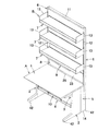
次に本発明の実施の形態を添付図面に基づき更に詳細に説明する。図1は本発明に係る棚板の取付装置を適用した棚付き机の全体斜視図、図2〜図4は各部材の組立構造を示し、図中符号Aは机、Bは棚、1は天板、2は脚部、3は幕板、4は下部棚板、5は連結部材、6は支柱、7は棚板、8は前面パネル、9は照明具、10は落下防止バーをそれぞれ示している。
【0011】
本実施形態の棚付き机は、図1に示すように、机Aの背後に棚Bを連結して構成したものである。前記机Aは、天板1の両側部に脚部2,2を固定するとともに、両脚部2,2の後端部間に幕板3を渡設して剛性を持たせ、天板1下の足入れ空間内であって、前記幕板3の前面側に下部棚板4を着脱可能に取付けたものである。ここで、本実施形態において、前記机Aは、通常の構造のスチール製机であり、既製のものを使用できる。また、前記棚Bは、前記机Aの両脚部2,2の後端にそれぞれ連結部材5,5を介して支柱6,6を立設し、該両支柱6,6に多段に棚板7,…を取付けるとともに、最下段の棚板7の下方であって両支柱6,6間に前面パネル8を着脱可能に取付け、更に所定高さの棚板7の下面に照明具9を着脱可能に取付けた構造のものである。そして、前記下部棚板4の前縁部に落下防止バー10を装着している。
【0012】
更に詳しくは、図2〜図4に示すように、前記机Aの両脚部2,2の後端部に連結部材5,5を介してそれぞれ支柱6,6を立設するとともに、両支柱6,6の上端間を横杆11で連結してフレーム構成し、前記支柱6の前面側に形成した係止孔12,…を利用してブラケット13を嵌合係止し、両ブラケット13,13で前記棚板7の両側端部を支持した構造となっている。
【0013】
ここで、前記脚部2の後端は、前記天板1の後端よりも前方位置に設定されたタイプの机Aを用いたため、前記連結部材5を介して支柱6を立設するようにしているが、脚部2の後端と天板1の後端が一致するタイプの机であれば、前記支柱6を直接脚部2の後端に取付けても良い。
【0014】
前記連結部材5は、図2〜図4に示すように、前記脚部2の後端と天板1の後端の間の隙間を埋める化粧板14の前縁に、脚部2の後端面に接合し且つ脚部2の後端部内面に連結するための平面視L字形の固定板15を直角に形成するとともに、化粧板14の後縁に前記支柱6の前面と内側面とに接合してネジ止めするための断面略L字形の取付板16を折曲形成したものである。尚、前記連結部材5の固定板15を前記脚部2の後端部内面に連結する構造は、本来、机Aの幕板3を連結するために用いていた構造をそのまま利用する。つまり、前記連結部材5の固定板15は、幕板3の端面を連結するためのネジを用いて取付けることができるようにし、その代わりに該連結部材5の固定板15より後方側に沿って幕板取付部17を固定している。この幕板取付部17は、本来、前記脚部2の幕板3を連結するために後端部内面に設けていた構造と同じ構造にしている。例えば、前記脚部2の後端部内面と幕板取付部17には螺孔18,…を形成してネジ19とネジピン20を螺合可能とし、前記固定板15にはネジ19にて締着するための通孔21,…を形成し、幕板取付部17の螺孔18に螺合したネジピン20に前記幕板3の端面に形成したダルマ孔22,…を嵌合係止するようにしている。ここで、前記連結部材5を介して脚部2に支柱6を連結した状態では、脚部2の外面、化粧板14及び支柱6の外側面とが面一になるように設定し、また外部からは前記固定板15及び取付板16は見えないようになっている。
【0015】
前記前面パネル8は、スチール製の表面板23の両側端に前記支柱6の内面へ取付ける端板24,24を形成するとともに、表面板23の下縁に前方へ直角に突出した閉塞板25を一体形成し、更に該閉塞板25の前端に下方へ直角に補強部26を一体形成し、前記閉塞板25を前記机Aの天板1の上面と面一に設定するとともに、前記補強部26を天板1の後端面に接合した状態で前記端板24,24を両支柱6,6の内側面に着脱可能に取付けている。つまり、前記前面パネル8は、両支柱6,6間の間隔に一致した横幅の表面板23と、その下端の閉塞板25とで側面視略L字形となっている。ここで、両支柱6,6間に前面パネル8を取付けることにより、棚Bの剛性が高くなり、強度が増すとともに、天板1と閉塞板25が面一になるので、天板面が拡張するばかりでなく、天板1の後方に筆記具や書類等の物品の落下を防止できる。また、前面パネル8は、背後を隠すので目隠しの働きをなし、更にその前面に書類をマグネットで吸着して保持することができ、掲示ボードとしても利用できる。
【0016】
更に詳しくは、前記前面パネル8は、図3及び図4に示すように、表面板23の両側縁を後方へ折曲して前記端板24,24を形成するとともに、表面板23の上縁を後方へ折曲して上板27を形成し、前記端板24,24に形成した通孔28,28を利用してネジ29で前記支柱6の内側面の後端寄りに螺合して取付ける。しかし、前記前面パネル8を支柱6へ取付ける構造は、特に限定されるものではない。また、前記前面パネル8の表面板23の下縁に形成した閉塞板25の前端には、補強部26を一体形成しているが、該補強部26は垂直な当接板30とその下縁に後方へ向け、更にその後端を立ち上げて形成したL字形補強板31からなっている。従って、前記前面パネル8は、閉塞板25と補強部26とで曲げ剛性が高くなっているが、強度が不足する場合には、表面板23の背面に横方向に補強部材を固定しても何ら差し支えない。
【0017】
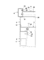
次に、前記前面パネル8の他の実施形態を図5及び図6に基づいて説明する。本実施形態の前面パネル8は、上部パネル8Aと下部パネル8Bとに分離して構成したものである。前記上部パネル8Aは、表面板23Aの両側端に端板24A,24Aを形成し、該端板24Aには前記支柱6の内側面の上下部に突設したネジピン32,32を前面側から受入れて落し込み係合する係合孔33,33を形成し、下端縁には表面板23Aから後方上方へ立ち上がった傾斜板34を有している。また、前記下部パネル8Bは、上下幅の狭い表面板23Bの下縁に前方へ直角に突出した閉塞板25Bを一体形成し、更に該閉塞板25Bの前端に下方へ直角に補強部26Bを一体形成し、更に表面板23Bの両側端の端板24B,24Bには、下端に前記支柱6の内側面に突設したネジピン35に上方から係合する切欠孔36を形成するとともに、端板24Bの上部には支柱6の内側面にネジ37にて締着するための通孔38を形成している。
【0018】
そして、前記両支柱6,6の内側面であって、上部前方寄り位置に前記上部パネル8Aを着脱可能に取付けるとともに、下部後方寄り位置に前記下部パネル8Bを取付けている。尚、前記上部パネル8Aと下部パネル8Bの間には、図7に示すように、隙間39が形成されるように取付けている。また、本実施形態でも、前記下部パネル8Bの前記閉塞板25Bを前記机Aの天板1の上面と面一に設定するとともに、前記補強部26Bを天板1の後端面に接合した状態で取付けている。
【0019】
図7は、本実施形態の棚付き机を2台背面合わせで設置した使用例であり、その場合、前後に位置する前記上部パネル8A,8A間と下部パネル8B,8B間は配線用空間40として利用できる。例えば、最下段の棚板7の下面に取付けた照明具9への電源コード41を、前述の配線用空間40に配線することができる。また、天板1の上面に電気機器を載置した場合、その電気機器への配線コードを前記隙間39から通して配線することができる。
【0020】
また、本実施形態の棚付き机は、棚Bの背が高いので、地震等の振動によって移動したり、後方へ倒れる恐れもある。しかし、棚付き机を単独で壁面に沿わせて設置している場合や、2台背面合わせで設置した場合には、倒れる恐れはないが、やはり移動することは考えられる。そこで、前記机Aの脚部2の下端や支柱6の下端に設けるアジャスター42に、図8に示すように、床面との摩擦係数が大きなゴム製等のキャップ43を外装することも好ましい。更に、図9に示すように、本発明に係る棚付き机を、島置き状態で単独に使用する場合には、前記支柱6の下部背後に直角三角形状の支持部材44を取付け、該支持部材44の下端後部に設けたアジャスター42に、前記キャップ43を装着すると、移動や傾倒の恐れがなくなり好ましい。
【0021】
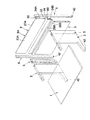
更に詳しく、図10及び図11に基づいて、前記棚板7をブラケット13,13にて前記支柱6,6に取付ける構造を説明する。前記棚板7は、載置板45の前縁に下方へ前面板46を形成するとともに、該前面板46の下端から後方へ下板47を形成し、更に該下板47の後端から立起片48を立ち上げ形成し、また前記載置板45の両側縁から下方へ側面板49を形成するとともに、該側面板49の下端から内方へ載支片50を形成して断面略L字形となしたものである。更に、前記棚板7は、載置板45の後端に上方へ立ち上げた突出部51を形成している。また、前記棚板7は、載置板45の下面で前後中間部に断面略コ字形の補強部材52を横設している。この補強部材52の前面側の垂直面53は、前記立起片48と平行となっており、該垂直面53の両端部で、前記載支片50の端縁の直上内側に縦長のスリット孔54を形成している。
【0022】
前記ブラケット13は、側面視略四角形の基板55の後端縁に、前記支柱6の係止孔12,…に嵌合係止する複数の下向きフック56,…を突設するとともに、前記基板55の下端に、前記棚板7の載支片50を載置する受板57を内向きに形成するとともに、該受板57の前部内側端に前記立起片48と垂直面53の間隔に略等しい長さの規制板58を立ち上げ形成している。更に、前記規制板58の後端には、前記補強部材52の垂直面53のスリット孔54に嵌入する爪片59を後向きに突設するとともに、前記規制板58の前端には下部に前記立起片48に当接する当接部60を形成し且つ上部に該当接部60よりも前方へ突出した規制部61を形成し、前記当接部60と規制部61の間は凹陥部62となっている。この凹陥部62の上下寸法は前記立起片48の上下寸法より大きく設定している。
【0023】
そして、前記ブラケット13を対応する支柱6の係止孔12,…に下向きフック56,…を嵌合係止して取付けた後、前記棚板7を前傾させた状態で前記凹陥部62に前記立起片48を受入れ、それから棚板7の後部を押し下げて前記規制板58を前記立起片48と補強部材52の垂直面53との間に進入させ、最後に棚板7を後退させて前記爪片59を垂直面53のスリット孔54に嵌入するとともに、前記当接部60を立起片48の後面に当止すると、前記棚板7の載支片50が前記ブラケット13の受板57に載置するとともに、該載支片50をブラケット13の基板55と規制板58とで内外から挟持するのである。この状態で、前記棚板7は前後左右の移動が完全に規制される。尚、前記棚板7を外す場合には、前述の手順を逆にすれば良いのである。ここで、前記棚板7の前部を単純に持ち上げても、前記立起片48の上端が規制部61の下縁に当止するので、不意に脱落することはないのである。
【0024】
また、前記棚板7を支持する両ブラケット13,13の前端部間に、落下防止バー63を渡設することも好ましい。それには、前記ブラケット13の基板55の前端部でやや上方に孔64を形成し、該孔64に外側から鍔付きキャップ65を嵌入すると同時に、両ブラケット13,13間に配した落下防止バー63の端部を鍔付きキャップ65の軸孔66に嵌入して保持する。
【0025】
次に、図12〜図14に基づいて、前記棚板7の下面に前記照明具9を取付ける構造を説明する。前記棚板7の構造は前記の通りであるが、この場合には更に前記補強部材52の垂直面53の中央寄り位置の2箇所に四角形の開口67,67を形成する。そして、前記照明具9を取付ける取付部材68の後端を前記開口67に挿入するとともに、該取付部材68の前端を前記下板47と立起片48とに係止するようになっている。
【0026】
更に詳しくは、前記取付部材68は、凹溝部を上方へ向けた断面略コ字形の部材であり、前端に下方へ係止片69を形成するとともに、中間部適所にネジ孔70を形成したものである。ここで、前記ネジ孔70は、バーリングタップで形成したが、ナットを固着しても良い。前記取付部材68の長さは、前記補強部材52の垂直面53の前面から前記立起片48の前面までの距離よりも長く、前記前面板46の後面までの距離よりも短く設定している。尚、前記照明具9は、ネジ71で直接取付面に取付ける構造の市販品の蛍光灯であり、上面の両端部には取付孔72を有する取付板73が予め備わっているものである。従って、前記開口67,67の位置と間隔及び前記取付部材68に設けるネジ孔70の位置は、前記照明具9の取付孔72,72の位置で決定される。
【0027】
そして、前記取付部材68,68を用いて前記照明具9を棚板7の下面に取付ける手順を図13及び図14に基づいて説明する。先ず、図13(a)に示すように、前記取付部材68の前部を上方へ持ち上げた傾斜状態で、前記取付部材68の前端部の係止片69を前記立起片48の上方を通過させて前方へ挿入し、それから図13(b)に示すように、前記取付部材68の後部を持ち上げて前記載置板45の下面に沿わせ、そして図13(c)に示すように、前記取付部材68を後方へスライド移動させてその後端部を前記開口67に挿入するとともに、前記係止片69を前記立起片48の前面側に当止する。この状態で、図14に示すように、下方から照明具9を両取付部材68,68にあてがい、取付板73の取付孔72からネジ71を通して前記取付部材68のネジ孔70に螺合して取付ける。この際、図14に示すように、前記照明具9の前端が前記棚板7の立起片48の後面側に当接又は接近するような寸法関係に設定する。こうすることで、前記照明具9に固定された取付部材68の係止片69と該照明具9の前端とで、前記棚板7の立起片48を前後から挟み込み、前後方向の移動が規制されるのである。尚、前記照明具9の後端と前記補強部材52の垂直面53との間には大きな間隔があっても差し支えない。
【0028】
ここで、前記照明具9の上端と、前記棚板7の載置板45の下面間には、少なくとも前記取付部材68の厚み分の空間が形成されるので、この空間を利用して照明具9の電源コードを所定位置まで引き出すことができ、また取付部材68を設けた部分は、前記棚板7の前面板46と下板47と立起片48とで形成される横方向に連続した空間を利用して迂回させることができる。
【0029】
【発明の効果】
以上にしてなる請求項1に係る発明の棚板の取付装置によれば、棚板の取付作業が極めて簡単であるとともに、ネジ止め等の固定手段を一切使用せずに、単に嵌合のみで前後左右の移動が規制され、更には上方への外れ防止もなされる安価な棚板の取付装置を提供できる。
【0030】
請求項2によれば、規制板の爪片を補強部材のスリット孔に嵌入する際に、規制板で載支片の端縁が案内されるので、爪片をスリット孔に簡単に嵌入することができる。
【0031】
請求項3によれば、ブラケットに対して棚板を落し込み嵌合させる際に、凹陥部内に立起片を受入れて棚板を若干前方へ移動させるので、爪片をスリット孔に簡単に嵌入することができるのである。
【0032】
請求項4によれば、ブラケットに対して棚板の左右移動を確実に規制することができるのである。
【図面の簡単な説明】
【図1】本発明に係る棚板の取付装置を適用した棚付き机の全体斜視図である。
【図2】棚付き机の基本構造の分解斜視図である。
【図3】同じく組立てた状態の部分横断面図である。
【図4】同じく組立てた状態の部分縦断面図である。
【図5】前面パネルの他の実施形態を示す分解斜視図である。
【図6】同じく拡大部分分解斜視図である。
【図7】本実施形態の2台の棚付き机を背面合わせで設置した状態を、棚部分を断面で示した側面図である。
【図8】机の脚部に設けたアジャスターを示し、(a)は縦断面図、(b)は斜視図をそれぞれ示している。
【図9】棚付き机を島置き状態で単独に使用する場合を実施形態を示す側面図である。
【図10】ブラケットにて棚板を支柱に取付ける構造を示す部分縦断面図である。
【図11】同じく分解斜視図である。
【図12】棚板の下面に照明具を取付ける構造を示す部分分解斜視図である。
【図13】同じく棚板に照明具を取付ける支持部材を装着する手順を示した部分断面図である。
【図14】棚板の下面に照明具を取付けた状態の部分縦断面図である。
【符号の説明】
A 机 B 棚
1 天板 2 脚部
3 幕板 4 下部棚板
5 連結部材 6 支柱
7 棚板 8 前面パネル
8A 上部パネル 8B 下部パネル
9 照明具 10 落下防止バー
11 横杆 12 係止孔
13 ブラケット 14 化粧板
15 固定板 16 取付板
17 幕板取付部 18 螺孔
19 ネジ 20 ネジピン
21 通孔 22 ダルマ孔
23、23A、23B 表面板
24、24A、25B 端板
25、25B 閉塞板 26、26B 補強部
27 上板 28 通孔
29 ネジ 30 当接板
31 補強板 32 ネジピン
33 係合孔 34 傾斜板
35 ネジピン 36 切欠孔
37 ネジ 38 通孔
39 隙間 40 配線用空間
41 電源コード 42 アジャスター
43 キャップ 44 支持部材
45 載置板 46 前面板
47 下板 48 立起片
49 側面板 50 載支片
51 突出部 52 補強部材
53 垂直面 54 スリット孔
55 基板 56 下向きフック
57 受板 58 規制板
59 爪片 60 当接部
61 規制部 62 凹陥部
63 落下防止バー 64 孔
65 鍔付きキャップ 66 軸孔
67 開口 68 取付部材
69 係止片 70 ネジ孔
71 ネジ 72 取付孔
73 取付板[0001]
BACKGROUND OF THE INVENTION
The present invention relates to a shelf mounting device, and more particularly to a shelf mounting device for mounting a shelf to a support via a bracket.
[0002]
[Prior art]
2. Description of the Related Art Conventionally, in a shelf apparatus, a structure in which brackets are attached to pillars erected on both sides and a shelf board is supported by both brackets is very common.
[0003]
In this case, a receiving plate for supporting the side edge portion of the shelf board is formed inward at the lower end of the bracket, and further, the front edge portion of the shelf board and the rear side thereof are restricted in order to restrict the movement of the shelf board in the front-rear direction. Also known is a structure in which a restricting plate fitted between reinforcing members arranged horizontally is installed on the inner end of the receiving plate.
[0004]
However, in the above-described structure, if the shelf board is lifted, it can be easily detached from the bracket, and the shelf board may be unexpectedly dropped due to vibration such as an earthquake. Therefore, conventionally, a fixing means such as screwing the shelf board to the bracket has been added. However, when fixing means such as screwing are employed in this way, the work of attaching the shelf board takes time and tends to be costly.
[0005]
[Problems to be solved by the invention]
In view of the above-mentioned situation, the present invention intends to solve the problem that the bracket is attached to the pillars erected on both sides and the shelf board is supported by both brackets, and the installation work of the shelf board is extremely simple. It is an object of the present invention to provide a low-priced shelf mounting device that restricts forward / backward / left / right movement by merely fitting without using any fixing means such as screwing, and further prevents upward disengagement. .
[0006]
[Means for Solving the Problems]
In order to solve the above-mentioned problems, the present invention is a shelf mounting apparatus that attaches brackets to pillars erected on both sides and supports the shelf board with both brackets, and the shelf board is a mounting board. A front plate is formed downward on the front edge, a lower plate is formed from the lower end of the front plate to the rear, and a standing piece is raised from the rear end of the lower plate. A side plate is formed downward from the edge and a support piece is formed inward from the lower end of the side plate to form a substantially L-shaped cross section. The reinforcing member is horizontally provided, vertically long slit holes are formed at both ends of the vertical surface on the front side of the reinforcing member, and the bracket is a receiving plate on which the support piece of the shelf plate is placed at the lower end of the substrate And a restriction of a length substantially equal to the distance between the upright piece and the vertical surface at the front inner end of the receiving plate Further, at the rear end of the restriction plate, a claw piece that fits into the slit hole of the vertical surface is projected rearward, and the front end of the restriction plate is contacted with the rising piece at the lower part. A shelf mounting device is formed, in which a contact portion is formed which is in contact with each other and a restriction portion which protrudes forward from the corresponding contact portion is formed on the upper portion.
[0007]
Here, the vertical surface on the front side of the reinforcing member is parallel to the upright piece, and a vertically long slit hole is formed at the both ends of the vertical surface directly above the edge of the support piece. It is preferable that
[0008]
Moreover, it is also preferable that a recessed portion is formed between the contact portion and the restricting portion of the restriction plate of the bracket, and the vertical dimension of the concave portion is set larger than the vertical dimension of the upright piece.
[0009]
More preferably, the mounting piece of the shelf plate is placed on the receiving plate of the bracket, and the mounting piece is sandwiched between the inside and outside of the bracket substrate and the regulating plate.
[0010]
DETAILED DESCRIPTION OF THE INVENTION
Next, embodiments of the present invention will be described in more detail with reference to the accompanying drawings. FIG. 1 is an overall perspective view of a shelf-equipped desk to which a shelf mounting device according to the present invention is applied. FIGS. 2 to 4 show the assembly structure of each member, in which A is a desk, B is a shelf, Top plate, 2 is a leg, 3 is a curtain plate, 4 is a lower shelf, 5 is a connecting member, 6 is a column, 7 is a shelf, 8 is a front panel, 9 is a lighting fixture, and 10 is a fall prevention bar. Show.
[0011]
The shelf-equipped desk according to the present embodiment is configured by connecting a shelf B behind the desk A, as shown in FIG. The desk A fixes the
[0012]
More specifically, as shown in FIGS. 2 to 4,
[0013]
Here, since the rear end of the
[0014]
As shown in FIGS. 2 to 4, the connecting
[0015]
The
[0016]
More specifically, as shown in FIGS. 3 and 4, the
[0017]
Next, another embodiment of the
[0018]
The
[0019]
FIG. 7 shows an example of use in which two desks with shelves according to the present embodiment are installed back to back. In this case, a
[0020]
In addition, since the shelf-equipped desk of the present embodiment has a tall shelf B, it may move due to vibration such as an earthquake or fall backward. However, when the desk with shelves is installed along the wall alone, or when the two desks are installed back to back, there is no fear of falling, but it is still possible to move. Therefore, it is also preferable that the
[0021]
In more detail, based on FIG.10 and FIG.11, the structure which attaches the said
[0022]
The
[0023]
Then, after attaching the
[0024]
It is also preferable to provide a
[0025]
Next, based on FIGS. 12-14, the structure which attaches the said
[0026]
More specifically, the mounting
[0027]
A procedure for attaching the
[0028]
Here, a space corresponding to at least the thickness of the mounting
[0029]
【The invention's effect】
According to the shelf mounting apparatus of the invention according to
[0030]
According to the second aspect, when the claw piece of the restriction plate is fitted into the slit hole of the reinforcing member, the edge of the mounting piece is guided by the restriction plate, so that the claw piece can be easily fitted into the slit hole. Can do.
[0031]
According to the third aspect, when the shelf plate is dropped and fitted to the bracket, the upright piece is received in the recessed portion and the shelf plate is moved slightly forward so that the claw piece can be easily fitted into the slit hole. It can be done.
[0032]
According to the fourth aspect, the left-right movement of the shelf plate with respect to the bracket can be reliably restricted.
[Brief description of the drawings]
FIG. 1 is an overall perspective view of a shelf-equipped desk to which a shelf mounting device according to the present invention is applied.
FIG. 2 is an exploded perspective view of a basic structure of a desk with a shelf.
FIG. 3 is a partial cross-sectional view of the assembled state.
FIG. 4 is a partial longitudinal sectional view of the assembled state.
FIG. 5 is an exploded perspective view showing another embodiment of the front panel.
FIG. 6 is an enlarged partial exploded perspective view of the same.
FIG. 7 is a side view showing a section of a shelf portion in a state where two desks with shelves according to the present embodiment are installed back to back.
8A and 8B show an adjuster provided on a leg portion of a desk. FIG. 8A is a longitudinal sectional view, and FIG. 8B is a perspective view.
FIG. 9 is a side view showing an embodiment when a desk with shelves is used alone in an island state.
FIG. 10 is a partial longitudinal sectional view showing a structure in which a shelf board is attached to a column with a bracket.
FIG. 11 is an exploded perspective view of the same.
FIG. 12 is a partially exploded perspective view showing a structure for attaching a lighting fixture to the lower surface of the shelf board.
FIG. 13 is a partial cross-sectional view showing a procedure for mounting a support member for attaching a lighting fixture to the shelf board.
FIG. 14 is a partial longitudinal sectional view of a state in which a lighting fixture is attached to the lower surface of the shelf board.
[Explanation of symbols]
A
Claims (4)
Priority Applications (1)
| Application Number | Priority Date | Filing Date | Title |
|---|---|---|---|
| JP2002174091A JP3758607B2 (en) | 2002-06-14 | 2002-06-14 | Shelf board mounting device |
Applications Claiming Priority (1)
| Application Number | Priority Date | Filing Date | Title |
|---|---|---|---|
| JP2002174091A JP3758607B2 (en) | 2002-06-14 | 2002-06-14 | Shelf board mounting device |
Publications (2)
| Publication Number | Publication Date |
|---|---|
| JP2004016402A JP2004016402A (en) | 2004-01-22 |
| JP3758607B2 true JP3758607B2 (en) | 2006-03-22 |
Family
ID=31173151
Family Applications (1)
| Application Number | Title | Priority Date | Filing Date |
|---|---|---|---|
| JP2002174091A Expired - Fee Related JP3758607B2 (en) | 2002-06-14 | 2002-06-14 | Shelf board mounting device |
Country Status (1)
| Country | Link |
|---|---|
| JP (1) | JP3758607B2 (en) |
Families Citing this family (3)
| Publication number | Priority date | Publication date | Assignee | Title |
|---|---|---|---|---|
| JP4598539B2 (en) * | 2005-01-14 | 2010-12-15 | 株式会社岡村製作所 | Shelf board equipment |
| JP5671424B2 (en) * | 2011-07-29 | 2015-02-18 | 三協立山株式会社 | shelf |
| JP2015047359A (en) * | 2013-09-02 | 2015-03-16 | 株式会社岡村製作所 | Laboratory table provided with shelf board structure and shelf board |
-
2002
- 2002-06-14 JP JP2002174091A patent/JP3758607B2/en not_active Expired - Fee Related
Also Published As
| Publication number | Publication date |
|---|---|
| JP2004016402A (en) | 2004-01-22 |
Similar Documents
| Publication | Publication Date | Title |
|---|---|---|
| JP2008086534A (en) | Shelf board support device in storage rack | |
| JP5720277B2 (en) | Wiring duct device in panel desk system | |
| JP3758607B2 (en) | Shelf board mounting device | |
| JP2006204679A (en) | Top board supporting structure | |
| JP3912268B2 (en) | Panel mounting structure and assembly-type counter device using the same | |
| JP2004016401A (en) | Desk with shelf | |
| JP4274065B2 (en) | Mounting device for supporting member | |
| JP4518814B2 (en) | Stabilizer for partition panel | |
| JP2004016403A (en) | Device for attaching light to shelf board | |
| JP4892256B2 (en) | Shelf equipment | |
| JP4306215B2 (en) | Assembled desk system | |
| JP2007267992A (en) | Structure for attaching panel to top plate elevating and lowering type table | |
| JP2010125015A (en) | Desk panel and mounting structure for the same | |
| JP4765603B2 (en) | Study desk desk shelf | |
| JP2008121314A (en) | Panel-like matter mounting structure | |
| JP4319518B2 (en) | Table with shelf | |
| JP3837616B2 (en) | Desk with shelf | |
| JP5143530B2 (en) | Bookcase | |
| JP4882484B2 (en) | Partition plate mounting device for learning furniture | |
| JP2013022410A (en) | Rack device, and joint metal used for the same | |
| JP4598539B2 (en) | Shelf board equipment | |
| JP2017089231A (en) | Partition panel device | |
| KR20070093730A (en) | Structure of mounting a shelf on a desk | |
| JP2003184210A (en) | Partition-wall structure of residence | |
| JP2004160039A (en) | Double-tilted surface type showcase |
Legal Events
| Date | Code | Title | Description |
|---|---|---|---|
| A621 | Written request for application examination |
Free format text: JAPANESE INTERMEDIATE CODE: A621 Effective date: 20040630 |
|
| A977 | Report on retrieval |
Free format text: JAPANESE INTERMEDIATE CODE: A971007 Effective date: 20051207 |
|
| TRDD | Decision of grant or rejection written | ||
| A01 | Written decision to grant a patent or to grant a registration (utility model) |
Free format text: JAPANESE INTERMEDIATE CODE: A01 Effective date: 20051213 |
|
| A61 | First payment of annual fees (during grant procedure) |
Free format text: JAPANESE INTERMEDIATE CODE: A61 Effective date: 20051226 |
|
| R150 | Certificate of patent or registration of utility model |
Free format text: JAPANESE INTERMEDIATE CODE: R150 |
|
| FPAY | Renewal fee payment (event date is renewal date of database) |
Free format text: PAYMENT UNTIL: 20090113 Year of fee payment: 3 |
|
| FPAY | Renewal fee payment (event date is renewal date of database) |
Free format text: PAYMENT UNTIL: 20100113 Year of fee payment: 4 |
|
| LAPS | Cancellation because of no payment of annual fees |