JP5720277B2 - Wiring duct device in panel desk system - Google Patents

Wiring duct device in panel desk system Download PDF

Info

Publication number
JP5720277B2
JP5720277B2 JP2011022682A JP2011022682A JP5720277B2 JP 5720277 B2 JP5720277 B2 JP 5720277B2 JP 2011022682 A JP2011022682 A JP 2011022682A JP 2011022682 A JP2011022682 A JP 2011022682A JP 5720277 B2 JP5720277 B2 JP 5720277B2
Authority
JP
Japan
Prior art keywords
panel
frame
plate
attached
leg
Prior art date
Legal status (The legal status is an assumption and is not a legal conclusion. Google has not performed a legal analysis and makes no representation as to the accuracy of the status listed.)
Active
Application number
JP2011022682A
Other languages
Japanese (ja)
Other versions
JP2012161405A (en
Inventor
賢訓 湯川
賢訓 湯川
貴司 小笠原
貴司 小笠原
Current Assignee (The listed assignees may be inaccurate. Google has not performed a legal analysis and makes no representation or warranty as to the accuracy of the list.)
Itoki Corp
Original Assignee
Itoki Corp
Priority date (The priority date is an assumption and is not a legal conclusion. Google has not performed a legal analysis and makes no representation as to the accuracy of the date listed.)
Filing date
Publication date
Application filed by Itoki Corp filed Critical Itoki Corp
Priority to JP2011022682A priority Critical patent/JP5720277B2/en
Publication of JP2012161405A publication Critical patent/JP2012161405A/en
Application granted granted Critical
Publication of JP5720277B2 publication Critical patent/JP5720277B2/en
Active legal-status Critical Current
Anticipated expiration legal-status Critical

Links

Images

Description

本発明は、パネルデスクシステムにおける配線ダクト装置に係わり、更に詳しくはパネルフレームを側方へ順次連結するとともに、該パネルフレームに連結した端部脚と支持脚の上位に天板を取付けてなるパネルデスクシステムにおける配線ダクト装置に関するものである。   The present invention relates to a wiring duct device in a panel desk system, and more particularly, a panel in which panel frames are sequentially connected to the side, and a top plate is attached above the end legs and support legs connected to the panel frame. The present invention relates to a wiring duct device in a desk system.

従来から、特許文献1に開示されるように、間仕切パネルの縦枠同士を連結し、あるいは隣接する間仕切パネルを支柱を介して連結し、間仕切パネルの縦枠又は支柱に設けた係止孔に、ブラケットのフックを係止し、該ブラケットに机天板を載置して固定するとともに、適宜な縦枠又は支柱に脚部材を取付けて自立するようにした構造の机天板付き間仕切装置は公知である。   Conventionally, as disclosed in Patent Document 1, the vertical frames of the partition panels are connected to each other, or adjacent partition panels are connected to each other through a support column. A partition device with a tabletop plate having a structure in which a hook of the bracket is locked and a tabletop plate is placed and fixed on the bracket and a leg member is attached to an appropriate vertical frame or column to be self-supporting. It is known.

一方、特許文献2,3に開示されるように、端部脚、中間脚、ダクト機能を備えた脚間モジュール、天板等の基本構成部材を用いて、側方へ順次連結して所望の形態のデスクシステムを構成する組立式デスクも提供されている。   On the other hand, as disclosed in Patent Documents 2 and 3, by using basic components such as end legs, intermediate legs, an inter-leg module having a duct function, and a top plate, the side legs are sequentially connected to a desired side. An assembling desk that constitutes a form of desk system is also provided.

しかし、特許文献1に記載のものは、配線受けを設ける場合、前記縦枠又は支柱の係止孔を利用して取付けるが、前記脚部材を取付けている箇所には配線受けを取付けることができない。また、配線受けを間仕切パネルに取付けたとしても、配線受けは露出状態となる。また、特許文献2,3に記載のものは、端部脚と中間脚及び中間脚同士を連結する脚間モジュールにダクト機能が備わっているので、ダクト内の配線が外部に露出することはないが、配線作業に手間がかかる。   However, although the thing of patent document 1 is attached using the latching hole of the said vertical frame or a support | pillar when providing a wiring receiver, a wiring receiver cannot be attached to the location which has attached the said leg member. . Even if the wiring receiver is attached to the partition panel, the wiring receiver is exposed. Moreover, since the thing of patent document 2, 3 is equipped with the duct function in the module between legs which connects an end leg, an intermediate leg, and intermediate legs, the wiring in a duct is not exposed outside. However, it takes time for wiring work.

特許文献4には、天板を支持する両側の脚部材の後部間を塞ぐ幕板の前面に、種類の異なる配線受けを上下に複数設け、その前面側に点検パネルを開閉可能且つ着脱可能に設けた構造が開示されている。この点検パネルは、両脚部材の上下部に内方へ固定ピンを突設し、下方の両固定ピンに、点検パネルの背面で下端両端部に設けた軸受金具を回動可能に係止するとともに、上方の両固定ピンに、点検パネルの背面で上端両端部に設けたラッチ部材に係脱可能に係止する構造である。このような、脚部材に点検パネル、あるいは幕板を取付ける構造の場合、脚部材の左右位置は固定的であり、このような構造をパネルデスクシステムに用いると、汎用性、拡張性に乏しいものとなる。   In Patent Document 4, a plurality of different types of wiring receptacles are provided on the front side of the curtain plate that closes the rear part of the leg members on both sides that support the top plate, and the inspection panel can be opened and closed on the front side. The provided structure is disclosed. This inspection panel has fixed pins projecting inwardly on the upper and lower parts of both leg members, and bearing brackets provided at both ends of the lower end on the back of the inspection panel are rotatably locked to both lower fixed pins. In this structure, the upper fixing pins are detachably engaged with latch members provided at both ends of the upper end on the back surface of the inspection panel. In the case of such a structure in which the inspection panel or curtain is attached to the leg member, the left and right positions of the leg member are fixed, and if such a structure is used for a panel desk system, the versatility and expandability are poor. It becomes.

特開2001−128753号公報JP 2001-128753 A 特開平10−155557号公報Japanese Patent Laid-Open No. 10-155557 特開2007−151824号公報JP 2007-151824 A 特開平06−000111号公報Japanese Patent Laid-Open No. 06-000111

そこで、本発明が前述の状況に鑑み、解決しようとするところは、パネルフレームを側方へ順次連結し、該パネルフレームの縦枠に端部脚と支持脚を連結するとともに、該端部脚と支持脚の上位に天板を取付けてなるパネルデスクシステムにおいて、端部脚や支持脚に関係なく配線受けと幕板を取付けることができ、パネルデスクシステムの汎用性、拡張性を損なうことがないパネルデスクシステムにおける配線ダクト装置を提供する点にある。   Therefore, in view of the above situation, the present invention intends to solve the problem by sequentially connecting the panel frame to the side, connecting the end legs and the support legs to the vertical frame of the panel frame, and the end legs. In a panel desk system that has a top plate attached to the top of the support legs, the wiring receiver and curtain can be attached regardless of the end legs or support legs, which may impair the versatility and expandability of the panel desk system. There is no wiring duct device in a panel desk system.

本発明は、前述の課題解決のために、パネルフレームを側方へ順次連結し、該パネルフレームの縦枠に端部脚と支持脚を連結するとともに、該端部脚と支持脚の上位に天板を取付け、該天板の後端とパネルフレームとの間にダクト開口を設けてなるパネルデスクシステムにおいて、前記パネルフレームは、両縦枠の上端部間に上横枠と下部間に下横枠を固着した構造であり、前記上横枠と下横枠の少なくとも一方に配線受けを設けるとともに、前記下横枠の左右両側部に取付けた支持金具で幕板の下端を支持するとともに、前記天板の下面両側部に取付けた係止金具で前記幕板の上部両側部を係着して取付けてなることを特徴とするパネルデスクシステムにおける配線ダクト装置を構成した(請求項)。 In order to solve the above-described problems, the present invention sequentially connects the panel frame to the side, connects the end legs and the support legs to the vertical frame of the panel frame, and connects the end legs and the support legs above the end legs. In a panel desk system in which a top plate is attached and a duct opening is provided between the rear end of the top plate and the panel frame, the panel frame is placed between the upper horizontal frame and the lower portion between the upper ends of both vertical frames. A structure in which a horizontal frame is fixed, and a wiring receiver is provided on at least one of the upper horizontal frame and the lower horizontal frame, and the lower end of the curtain plate is supported by support brackets attached to the left and right sides of the lower horizontal frame. The wiring duct device in the panel desk system is constructed by engaging and attaching the upper both side portions of the curtain plate with locking metal fittings attached to the lower surface both sides of the top plate (Claim 1 ).

ここで、前記下横枠の左右両側部に取付けた支持金具で前記幕板の下端を前後傾動可能に支持するとともに、前記天板の下面両側部に取付けた係止金具で前記幕板の上部両側部に設けたラッチを係着して取付けてなることが好ましい(請求項)。 Here, the lower end of the curtain plate is supported so as to be able to tilt forward and backward with support brackets attached to the left and right side portions of the lower horizontal frame, and the upper portion of the curtain plate is secured with locking brackets attached to the lower side sides of the top plate. It is preferable that the latches provided on both sides are fixedly attached (claim 2 ).

具体的には、前記下横枠に取付ける下部配線受けは、垂直板の上縁に断面L字形の受部を形成し、前記垂直板の両側下端部に下方に開放したU字孔を形成し、前記支持金具は、前記下横枠の前面に当接する垂直板の上端に通孔を形成し、前記支持金具の通孔に挿通したネジを前記下横枠の前面に設けた螺孔に緩く螺合するとともに、前記下部配線受けのU字孔を前記ネジの軸部に上方から係合した後、前記ネジを締め付けてなることが好ましい(請求項)。 Specifically, the lower wiring receiver attached to the lower horizontal frame has a receiving portion having an L-shaped cross section at the upper edge of the vertical plate, and U-shaped holes opened downward at both lower ends of the vertical plate. The support fitting is formed with a through hole at an upper end of a vertical plate that contacts the front surface of the lower horizontal frame, and a screw inserted into the through hole of the support metal fitting is loosened in a screw hole provided on the front surface of the lower horizontal frame. with screwed, after the U-shaped hole of receiving the lower wire engaged from above the shaft portion of the screw is preferably made by tightening the screw (claim 3).

更に、前記支持金具は、下部の水平板の前端に斜めに立ち上がった係止片を形成し、前記幕板の下部に形成した支持孔を前記係止片に落とし込んで挿入して前後傾動可能とし、前記天板の下面に固定した前記係止金具の下端部に設けた係止ピンに前記幕板の上部両側部に設けたラッチを係脱可能に係着してなることがより好ましい(請求項)。 Further, the support bracket forms a locking piece that rises obliquely at the front end of the lower horizontal plate, and a support hole formed in the lower part of the curtain plate is inserted into the locking piece so that it can tilt forward and backward. More preferably, latches provided at both upper side portions of the curtain plate are detachably engaged with locking pins provided at a lower end portion of the locking fitting fixed to the lower surface of the top plate. Item 4 ).

以上にしてなる請求項に係る発明のパネルデスクシステムにおける配線ダクト装置は、パネルフレームを側方へ順次連結し、該パネルフレームの縦枠に端部脚と支持脚を連結するとともに、該端部脚と支持脚の上位に天板を取付け、該天板の後端とパネルフレームとの間にダクト開口を設けてなるパネルデスクシステムにおいて、前記パネルフレームは、両縦枠の上端部間に上横枠と下部間に下横枠を固着した構造であり、前記上横枠と下横枠の少なくとも一方に配線受けを設けるとともに、前記下横枠の左右両側部に取付けた支持金具で幕板の下端を支持するとともに、前記天板の下面両側部に取付けた係止金具で前記幕板の上部両側部を係着して取付けてなるので、端部脚や支持脚に関係なく配線受けと幕板を取付けることができ、パネルデスクシステムの汎用性、拡張性を損なうことがないのである。また、パネルフレームの上横枠と下横枠にそれぞれ上部配線受けと下部配線受けとを設ければ、大容量のコード、ケーブルを配線することができ、強電の電源コード類と弱電の信号ケーブル類を分けて配線し、信号ケーブルに雑音が入らないようにすることも可能であり、前記パネルフレームの表裏両面に対面させて天板を設ける対面デスク態様では、パネルフレームにはパネル板を取付けなくても、前面側に幕板を有するので、配線受けが露出することがなく、それぞれの天板の下方の奥部に設けた幕板で囲まれる広い空間を配線に利用することができる。その場合、パネルフレームを通して前後に自由に配線することが可能である。一方、パネルフレームの表側にのみ天板を設けた片面デスク態様では、パネルフレームの裏面側にパネル板を取付けて配線受けが外部から見えなくして、背後からは間仕切パネルのような外観とすることができる。 The wiring duct system in a panel desk system of the invention according to claim 1 consisting in the above, the panel frame sequentially connected laterally, as well as connecting the end legs and the support legs in the vertical frame of the panel frame, said end In a panel desk system in which a top plate is attached above the base and support legs, and a duct opening is provided between the rear end of the top plate and the panel frame, the panel frame is between the upper ends of both vertical frames. A structure in which a lower horizontal frame is fixed between an upper horizontal frame and a lower portion, and wiring receivers are provided on at least one of the upper horizontal frame and the lower horizontal frame, and a curtain is provided by support brackets attached to the left and right sides of the lower horizontal frame. The lower end of the plate is supported and the upper both sides of the curtain plate are fixedly attached to the both sides of the lower surface of the top plate. Can be installed and Versatility Le desk system is of no impairing the extensibility. Also, if an upper wiring receiver and a lower wiring receiver are provided on the upper and lower horizontal frames of the panel frame, respectively, large-capacity cords and cables can be wired. It is also possible to divide the cables separately so that noise does not enter the signal cable. In the face-to-face desk mode where the top panel is provided facing both the front and back surfaces of the panel frame, the panel frame is attached to the panel frame. Even if it is not, since the curtain plate is provided on the front side, the wiring receiver is not exposed, and a wide space surrounded by the curtain plate provided in the lower part of each top plate can be used for wiring. In that case, it is possible to freely wire back and forth through the panel frame. On the other hand, in the single-sided desk mode in which the top panel is provided only on the front side of the panel frame, the panel board is attached to the back side of the panel frame so that the wiring receiver is not visible from the outside, and it looks like a partition panel from the back Can do.

請求項によれば、前記下横枠の左右両側部に取付けた支持金具で前記幕板の下端を前後傾動可能に支持するとともに、前記天板の下面両側部に取付けた係止金具で前記幕板の上部両側部に設けたラッチを係着して取付けてなるので、ラッチを係止金具から外せば、幕板を手前側へ傾斜させて開き、あるいは持ち上げれば取り外すことができるので、配線受けを露出させた状態で配線作業を行えるのである。 According to claim 2 , the lower end of the curtain plate is supported by the support brackets attached to the left and right sides of the lower horizontal frame so as to be able to tilt forward and backward, and the locking brackets attached to the lower sides of the top plate Since the latch provided on both sides of the upper part of the curtain is attached and attached, if the latch is removed from the locking bracket, it can be opened by tilting the curtain to the near side, or it can be removed by lifting. Wiring work can be performed with the wiring receiver exposed.

請求項によれば、前記下横枠に取付ける下部配線受けは、垂直板の上縁に断面L字形の受部を形成し、前記垂直板の両側下端部に下方に開放したU字孔を形成し、前記支持金具は、前記下横枠の前面に当接する垂直板の上端に通孔を形成し、前記支持金具の通孔に挿通したネジを前記下横枠の前面に設けた螺孔に緩く螺合するとともに、前記下部配線受けのU字孔を前記ネジの軸部に上方から係合した後、前記ネジを締め付けてなるので、下部配線受けと支持金具を同じネジで簡単且つ強固に下横枠に取付けることができる。また、天板下の狭い足入れ空間での作業になるが、前記支持金具の通孔に挿通したネジを前記下横枠の前面に設けた螺孔に緩く螺合するとともに、前記下部配線受けのU字孔を前記ネジの軸部に上方から係合した後、前記ネジを締め付けるので、一人でも簡単に取付けることができる。 According to a third aspect of the present invention, the lower wiring receiver attached to the lower horizontal frame is formed with a receiving portion having an L-shaped cross section at the upper edge of the vertical plate, and U-shaped holes opened downward at both lower ends of the vertical plate. The support bracket is formed with a through hole at the upper end of a vertical plate that contacts the front surface of the lower horizontal frame, and a screw hole that is inserted into the through hole of the support metal bracket is provided on the front surface of the lower horizontal frame. The U-shaped hole of the lower wiring receiver is engaged with the shaft portion of the screw from above, and then the screw is tightened. Can be mounted on the lower horizontal frame. Further, although the work is performed in a small foot space under the top plate, a screw inserted through the through hole of the support bracket is loosely screwed into a screw hole provided in the front surface of the lower horizontal frame, and the lower wiring receiver After the U-shaped hole is engaged with the shaft portion of the screw from above, the screw is tightened, so that even one person can easily attach it.

請求項によれば、前記支持金具は、下部の水平板の前端に斜めに立ち上がった係止片を形成し、前記幕板の下部に形成した支持孔を前記係止片に落とし込んで挿入して前後傾動可能とし、前記天板の下面に固定した前記係止金具の下端部に設けた係止ピンに前記幕板の上部両側部に設けたラッチを係脱可能に係着してなるので、構造が簡単で有るにも係わらず、幕板を確実に保持することができ、また幕板の開閉、取り外しも簡単に行えるのである。 According to a fourth aspect of the present invention, the support fitting forms a locking piece that rises obliquely at the front end of the lower horizontal plate, and the support hole formed in the lower portion of the curtain plate is dropped into the locking piece and inserted. It is possible to tilt forward and backward, and latches provided on both lower side portions of the curtain plate are detachably engaged with locking pins provided at a lower end portion of the locking bracket fixed to the lower surface of the top plate. Although the structure is simple, the curtain plate can be securely held, and the curtain plate can be easily opened and closed and removed.

本発明の配線ダクト装置を適用したパネルデスクシステムの簡略分解斜視図である。1 is a simplified exploded perspective view of a panel desk system to which a wiring duct device of the present invention is applied. パネルデスクシステムの一例を示し、対面フラットデスク態様の斜視図である。It is a perspective view of an example of a panel desk system, and a face-to-face flat desk mode. パネルデスクシステムの一例を示し、中間にフロントパネルを備えた対面デスク態様の斜視図である。It is a perspective view of the facing desk mode which showed an example of the panel desk system and was equipped with the front panel in the middle. パネルデスクシステムの一例を示し、高さの異なるフロントパネルを備え、一側に側面パネルを供えた片面デスク態様の斜視図である。It is a perspective view of the single-sided desk aspect which showed an example of the panel desk system, provided with the front panel from which height differs, and provided the side panel on the one side. パネルフレームの縦枠に支持脚を取付ける構造を示す分解斜視図である。It is a disassembled perspective view which shows the structure which attaches a support leg to the vertical frame of a panel frame. 同じくパネルフレームの縦枠に支持脚を取付けた状態の一部省略平面図である。It is a partially abbreviated top view of the state which similarly attached the support leg to the vertical frame of the panel frame. 連結したパネルフレームの両縦枠に渡って支持脚を取付ける構造を示す分解斜視図である。It is a disassembled perspective view which shows the structure which attaches a support leg over both the vertical frames of the connected panel frame. 同じく連結したパネルフレームの両縦枠に渡って支持脚を取付けた状態の一部省略平面図である。It is a partially abbreviated top view of the state which attached the support leg over both the vertical frames of the similarly connected panel frame. 支持脚をパネルフレームの縦枠に取付けるための脚連結金具を示し、(a)は斜視図、(b)は平面図、(c)は側面図、(d)は正面図を示している。The leg connection metal fitting for attaching a support leg to the vertical frame of a panel frame is shown, (a) is a perspective view, (b) is a top view, (c) is a side view, (d) has shown the front view. パネルフレームの縦枠に支持脚を取付けた状態の斜視図である。It is a perspective view of the state which attached the support leg to the vertical frame of the panel frame. 支持脚にパネル脚を取付ける構造を示す分解斜視図である。It is a disassembled perspective view which shows the structure which attaches a panel leg to a support leg. 支持脚にパネル脚を取付けた状態を示す斜視図である。It is a perspective view which shows the state which attached the panel leg to the support leg. 支持脚にパネル脚を取付けた状態を示す横断平面図である。It is a cross-sectional top view which shows the state which attached the panel leg to the support leg. パネルフレームの上端に延長フレームを連設する構造を示す分解斜視図である。It is a disassembled perspective view which shows the structure which connects the extension frame to the upper end of a panel frame. 配線ダクトの構造を示す部分断面図である。It is a fragmentary sectional view which shows the structure of a wiring duct. ダクト開口にダクトカバーを開閉可能に取付ける構造を示す部分斜視図である。It is a fragmentary perspective view which shows the structure which attaches a duct cover to a duct opening so that opening and closing is possible. 支持脚及び端部脚の上端後部に取付ける取付部材とダクトカバーを回動開閉可能に支持するヒンジ部材との関係を示し、(a)は断面図、(b)は平面図である。The relationship between the attachment member attached to the upper end rear part of a support leg and an end leg and the hinge member which supports a duct cover so that rotation opening and closing is possible is shown, (a) is sectional drawing, (b) is a top view. ヒンジ部材を示し、(a)は側面図、(b)は背面図、(c)は底面図である。The hinge member is shown, (a) is a side view, (b) is a rear view, and (c) is a bottom view. ダクトカバーの取付状態を示し、(a)はパネルフレームの上部にフロントパネル部を設けた場合の部分断面図、(b)パネルフレームの上端に笠木を設けた場合の部分断面図である。The state of the duct cover is shown, (a) is a partial cross-sectional view when the front panel portion is provided at the upper part of the panel frame, (b) is a partial cross-sectional view when the headboard is provided at the upper end of the panel frame. ダクトカバーの開閉動作を示し、(a)は閉じた状態の部分断面図、(b)は半分開いた状態の部分断面図、(c)は全部開いた場合の部分断面図である。The opening / closing operation | movement of a duct cover is shown, (a) is a fragmentary sectional view of a closed state, (b) is a fragmentary sectional view of a half open state, (c) is a fragmentary sectional view in the case of all opening. 配線ダクト装置を示す分解斜視図である。It is a disassembled perspective view which shows a wiring duct apparatus. 同じく配線ダクト装置の部分拡大斜視図である。It is a partial expansion perspective view of a wiring duct apparatus similarly. 幕板を装着する前の配線ダクト装置の部分正面図である。It is a partial front view of the wiring duct apparatus before mounting | wearing with a curtain. 配線ダクト装置の下部構造を示す部分拡大断面図である。It is a partial expanded sectional view which shows the lower part structure of a wiring duct apparatus.

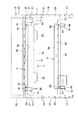
次に、添付図面に示した実施形態に基づき、本発明を更に詳細に説明する。図1は、本発明の配線ダクト装置を適用したパネルデスクシステムの構成部材を示す分解斜視図、図2〜図4はパネルデスクシステムの態様例を示し、図5〜図14はパネルデスクシステムの基本構成を示し、図中符号1はパネルフレーム、2は端部脚、3は支持脚、4はパネル脚、5は天板、6はダクトカバー、7は上部配線受け、8は下部配線受け、9は幕板、10は延長フレーム、11はパネル板、12は笠木、13は側カバーをそれぞれ示している。   Next, the present invention will be described in more detail based on the embodiments shown in the accompanying drawings. FIG. 1 is an exploded perspective view showing components of a panel desk system to which the wiring duct device of the present invention is applied, FIGS. 2 to 4 show examples of the panel desk system, and FIGS. 5 to 14 show the panel desk system. In the figure, reference numeral 1 is a panel frame, 2 is an end leg, 3 is a support leg, 4 is a panel leg, 5 is a top plate, 6 is a duct cover, 7 is an upper wiring receiver, and 8 is a lower wiring receiver. , 9 is a curtain plate, 10 is an extension frame, 11 is a panel plate, 12 is a headboard, and 13 is a side cover.

本実施形態に係るパネルデスクシステムは、図1に示すように、複数のパネルフレーム1,…を側方へ連結し、端部に位置する前記パネルフレーム1の縦枠14に前記端部脚2を取付けるとともに、中間に位置する前記パネルフレーム1の縦枠14に支持脚3,…を取付け、そして前記端部脚2と支持脚3の上位及び隣接する両側の支持脚3,3の上位に天板5を載置して固定する。前記天板5の後端と前記パネルフレーム1との間にダクト開口15を設けて、該ダクト開口15にダクトカバー6を開閉可能に設けている。また、前記ダクト開口15の下方で、前記パネルフレーム1の前面側に上部配線受け7と下部配線受け8とを取付け、その前面側に着脱可能且つ開閉可能に幕板9を取付けて配線装置を構成している。また、前記支持脚3には、必要に応じてパネル脚4を連結一体化し、あたかも端部脚2のように構成することも可能である。   In the panel desk system according to the present embodiment, as shown in FIG. 1, a plurality of panel frames 1,... Are connected laterally, and the end leg 2 is connected to the vertical frame 14 of the panel frame 1 located at the end. Are attached to the vertical frame 14 of the panel frame 1 positioned in the middle, and the upper ends of the end legs 2 and the supporting legs 3 and the upper supporting legs 3 and 3 on both adjacent sides. The top plate 5 is placed and fixed. A duct opening 15 is provided between the rear end of the top plate 5 and the panel frame 1, and a duct cover 6 is provided in the duct opening 15 so as to be openable and closable. An upper wiring receiver 7 and a lower wiring receiver 8 are attached to the front side of the panel frame 1 below the duct opening 15, and a curtain plate 9 is attached to the front side so as to be detachable and openable. It is composed. Further, if necessary, a panel leg 4 can be connected and integrated with the support leg 3 as if it were an end leg 2.

図2及び図3は、前記パネルフレーム1の両側に対称に天板5,5を配置した対面デスク態様を示している。本発明では、前記パネルフレーム1の高さは、その上端に笠木12を取付けた状態で、該笠木12の上面と前記天板5の上面とが略面一になるように設定されている。つまり、図2のように、前記パネルフレーム1の上端に笠木12を取付け、前記天板5の後端との間に設けたダクト開口15に前記ダクトカバー6を装着することにより、対面フラットデスク態様となる。また、図3のように、前記パネルフレーム1の上端に延長フレーム10を連結し、該延長フレーム10の表裏両面にパネル板11,11を取付けるとともに、該延長フレーム10の上端に笠木12、側端に側カバー13を取付けることにより、対面した天板5,5の中間に目隠し機能を有するフロントパネル部16を設けることができる。尚、前記パネルフレーム1の上端に笠木12を取付けた場合も、延長フレーム10とパネル板11とを取付けた場合も、前記ダクト開口15にはダクトカバー6を取付けることが可能である。   2 and 3 show a facing desk form in which the top plates 5 and 5 are symmetrically arranged on both sides of the panel frame 1. In the present invention, the height of the panel frame 1 is set so that the upper surface of the headboard 12 and the upper surface of the top plate 5 are substantially flush with the headboard 12 attached to the upper end thereof. That is, as shown in FIG. 2, the headboard 12 is attached to the upper end of the panel frame 1, and the duct cover 6 is attached to the duct opening 15 provided between the rear end of the top plate 5 and the facing flat desk. It becomes an aspect. Further, as shown in FIG. 3, an extension frame 10 is connected to the upper end of the panel frame 1, panel panels 11 and 11 are attached to both the front and back surfaces of the extension frame 10, and the headboard 12 is connected to the upper end of the extension frame 10. By attaching the side cover 13 to the end, the front panel portion 16 having a blindfold function can be provided in the middle of the facing top plates 5 and 5. The duct cover 6 can be attached to the duct opening 15 both when the headboard 12 is attached to the upper end of the panel frame 1 and when the extension frame 10 and the panel plate 11 are attached.

次に、各部の詳細を説明する。前記パネルフレーム1は、図1、図5及び図14に示すように、両側に縦枠14,14を有し、両縦枠14,14の上端部間に上横枠17と下部間に下横枠18を縦枠14の下端部を余して固着した構造である。前記上横枠17と下横枠18の表裏方向の厚さは縦枠14よりも約5mm程度狭く設定し、該パネルフレーム1の両縦枠14,14の表面側に前記パネル板11を装着した際に、前記上横枠17及び下横枠18とパネル板11の裏面との間の隙間を利用してコードを配線できるようにしている。前記両縦枠14,14の下端には、高さ調節可能なアジャスター19,19を設けている。そして、両縦枠14,14の表裏両面には、前記パネル板11の背面両側上下部に突設した係合部を係合して取付けるための開口20,…を上下方向に所定ピッチで形成するとともに、上下部と中間部に左右一対の係止孔21,21を形成している。また、前記上横枠17と下横枠18の表裏両面で上縁に沿って横方向に一定間隔で横長の係合孔22,…を形成し、該係合孔22,…は上下パネル板11,11の間及びパネル板11の上端と笠木12の間の横目地部23に露出するようになっている(図3及び図4参照)。前記パネルフレーム1,1同士は、互いの縦枠14,14の端面を接合した状態で、貫通したボルトとナットで側方へ連結する。この連結構造は、間仕切パネルの連結構造と同じである。   Next, details of each part will be described. As shown in FIGS. 1, 5 and 14, the panel frame 1 has vertical frames 14 and 14 on both sides, and an upper horizontal frame 17 and a lower portion between the upper ends of the vertical frames 14 and 14 and the lower portion. In this structure, the horizontal frame 18 is fixed with the lower end portion of the vertical frame 14 remaining. The thickness of the upper horizontal frame 17 and the lower horizontal frame 18 in the front and back direction is set to be about 5 mm narrower than the vertical frame 14, and the panel plate 11 is mounted on the surface side of both vertical frames 14, 14 of the panel frame 1. In this case, the cords can be wired using the gaps between the upper horizontal frame 17 and the lower horizontal frame 18 and the back surface of the panel plate 11. At the lower ends of the vertical frames 14, 14, there are provided adjusters 19, 19 whose height can be adjusted. And, on both front and back surfaces of the vertical frames 14, 14, openings 20,... For engaging and mounting engaging portions projecting from the upper and lower portions on both sides of the back surface of the panel plate 11 are formed at a predetermined pitch in the vertical direction. In addition, a pair of left and right locking holes 21 and 21 are formed in the upper and lower parts and the middle part. Further, on the front and back surfaces of the upper horizontal frame 17 and the lower horizontal frame 18, horizontally long engagement holes 22,... Are formed at regular intervals along the upper edge, and the engagement holes 22,. 11 and 11 and the horizontal joint 23 between the upper end of the panel plate 11 and the headboard 12 is exposed (see FIGS. 3 and 4). The panel frames 1 and 1 are connected to each other with a penetrating bolt and nut while the end faces of the vertical frames 14 and 14 are joined to each other. This connection structure is the same as the connection structure of the partition panel.

前記延長フレーム10は、図1及び図14に示すように、両側の縦枠24,24の上端部間に上横枠25を固着するとともに、下端部間に下横枠26を固着し、該縦枠24には前記縦枠14と同様に開口20,…を形成し、上横枠25にも前記上横枠17と同様に係合孔22,…を形成している。更に、前記延長フレーム10の両縦枠24,24の下端には、前記パネルフレーム1の両縦枠14,14の上端開口に嵌合する嵌合部27,27を下方へ向けて延設している。そして、前記パネルフレーム1の上に延長フレーム10を連結するには、前記延長フレーム10の両嵌合部27,27をパネルフレーム1の両縦枠14,14の上端開口に嵌合するとともに、パネルフレーム1の上横枠17と延長フレーム10の下横枠26を接合した状態で上下方向にボルトとナットで締結する。図4には、前記延長フレーム10の高さが異なる2種類のものを用いて、段違いのフロントパネル部16を構成している。尚、前記延長フレーム10は、複数を上方へ積み重ねて連結することができ、所望の高さの間仕切パネルを構成できる。   As shown in FIGS. 1 and 14, the extension frame 10 has an upper horizontal frame 25 fixed between upper ends of the vertical frames 24, 24 on both sides, and a lower horizontal frame 26 fixed between lower ends. Openings 20 are formed in the vertical frame 24 in the same manner as the vertical frame 14, and engagement holes 22 are formed in the upper horizontal frame 25 in the same manner as the upper horizontal frame 17. Further, at the lower ends of the vertical frames 24, 24 of the extension frame 10, fitting portions 27, 27 that fit into the upper end openings of the vertical frames 14, 14 of the panel frame 1 are extended downward. ing. And in order to connect the extension frame 10 on the said panel frame 1, while fitting both the fitting parts 27 and 27 of the said extension frame 10 to the upper end opening of both the vertical frames 14 and 14 of the panel frame 1, The panel frame 1 is fastened with bolts and nuts in the vertical direction with the upper horizontal frame 17 and the lower horizontal frame 26 of the extension frame 10 joined. In FIG. 4, a front panel portion 16 having a different level is configured using two types of extension frames 10 having different heights. A plurality of the extension frames 10 can be stacked and connected upward, and a partition panel having a desired height can be configured.

前記支持脚3は、図5及び図6に示すように、奥行幅が前記天板5よりも狭く前記パネルフレーム1の縦枠14の前面に沿って連結する脚板部28と、該脚板部28の上端から前方へ延び上位に前記天板5を取付ける支持アーム29とを有する逆L字形である。前記脚板部28の後端面には、前記縦枠14の下側二対の係止孔21,21に係止する下向きフック30,30を上下部に突設するとともに、後端部上部には脚連結金具31を受け入れ、上端後部から下方へ挿入した締結ボルト32で上方へ引き付けることができるようになっている。前記脚連結金具31は、図9に示すように、後側に前記縦枠14の最上方の一対の係止孔21,21に係止する上向きフック33,33を突設するとともに、上面板34に前記締結ボルト32を螺合する螺孔35を形成したものである。   As shown in FIGS. 5 and 6, the support leg 3 has a leg plate portion 28 that is narrower in depth than the top plate 5 and is connected along the front surface of the vertical frame 14 of the panel frame 1, and the leg plate portion 28. It has an inverted L-shape having a support arm 29 that extends forward from the upper end of the upper plate and has the upper plate 5 attached to the upper side. On the rear end surface of the leg plate portion 28, downward hooks 30, 30 that are engaged with the two lower pairs of engagement holes 21, 21 of the vertical frame 14 protrude from the upper and lower portions, and on the upper portion of the rear end portion. The leg connecting bracket 31 is received and can be pulled upward by the fastening bolt 32 inserted downward from the rear end of the upper end. As shown in FIG. 9, the leg connecting bracket 31 projects upward hooks 33, 33 that are engaged with the pair of uppermost locking holes 21, 21 of the vertical frame 14 on the rear side, and an upper surface plate. 34 is formed with a screw hole 35 into which the fastening bolt 32 is screwed.

そして、前記支持脚3を前記パネルフレーム1の縦枠14に連結するには、先ず前記脚連結金具31の上向きフック33,33を前記縦枠14の最上方の係止孔21,21に係止した状態で、前記支持脚3の下向きフック30,30をそれぞれ下側二対の係止孔21,21に係止するとともに、前記脚連結金具31を脚板部28の上端部内に受け入れる。それから、前記脚板部28の上端の通孔から挿入した前記締結ボルト32を脚連結金具31の螺孔35に螺合し、該脚連結金具31を上方へ引き上げると、それに伴って前記支持脚3が下方へ押し下げられ、前記下向きフック30は下方へ、上向きフック33は上方へ力が加わるので、強固に連結される。ここで、前記支持脚3の脚板部28の下端には、高さ調節可能なアジャスター36を設けてあり、調節して床面に接地させる。   In order to connect the support leg 3 to the vertical frame 14 of the panel frame 1, first, the upward hooks 33, 33 of the leg connecting bracket 31 are engaged with the uppermost locking holes 21, 21 of the vertical frame 14. In the stopped state, the downward hooks 30, 30 of the support leg 3 are locked in the two lower pairs of locking holes 21, 21, respectively, and the leg connecting bracket 31 is received in the upper end portion of the leg plate portion 28. Then, the fastening bolt 32 inserted from the upper end through-hole of the leg plate portion 28 is screwed into the screw hole 35 of the leg connecting metal 31 and the leg connecting metal 31 is pulled upward. Is pushed downward, and the downward hook 30 is downwardly connected and the upward hook 33 is upwardly connected, so that they are firmly connected. Here, an adjuster 36 capable of adjusting the height is provided at the lower end of the leg plate portion 28 of the support leg 3, and is adjusted to be grounded on the floor surface.

図5及び図6は、前記パネルフレーム1の各縦枠14にそれぞれ前記支持脚3を連結する例であるが、図7及び図8に示すように、連結したパネルフレーム1,1の両縦枠14,14の接合線に一つの前記支持脚3の中心が位置するように取付けることも可能である。それにより、中間部に設ける支持脚3の数を少なくすることができる。図7に示すように、連結したパネルフレーム1,1の両縦枠14,14の同じ高さ位置に、4つの係止孔21,…が存在するので、中央側の二つの係止孔21,21を選んで、前記同様に脚連結金具31を用いて支持脚3を取付けるのである。つまり、隣接する各パネルフレーム1の縦枠14の外側の係止孔21を一対用いるのである。取付方法は、前記と全く同様である。   5 and 6 show examples in which the support legs 3 are connected to the vertical frames 14 of the panel frame 1, respectively. As shown in FIGS. 7 and 8, both vertical frames of the connected panel frames 1 and 1 are used. It is also possible to attach so that the center of one said support leg 3 is located in the joining line of the frames 14 and 14. FIG. Thereby, the number of the support legs 3 provided in the intermediate part can be reduced. As shown in FIG. 7, since there are four locking holes 21,... At the same height position of both vertical frames 14, 14 of the connected panel frames 1, 1, two locking holes 21 on the center side are present. , 21 is selected, and the support leg 3 is attached using the leg connecting bracket 31 in the same manner as described above. That is, a pair of locking holes 21 outside the vertical frame 14 of each adjacent panel frame 1 is used. The attachment method is exactly the same as described above.

そして、前記支持脚3の支持アーム29に前記天板5を載置して固定するには、前記支持アーム29上端前後部に固定板37,37を取付け、該固定板37を天板5の下面にネジ止めして固定する。前記固定板37は、中心とその両側等距離に通孔38,…を有し、パネルフレーム1の各縦枠14にそれぞれ支持脚3を取付ける場合には、一端部の通孔38を用いて内側に突出するように前記固定板37をネジ39で固定する(図5参照)。一方、連結したパネルフレーム1,1の互いに接合した縦枠14,14の中央に一つの支持脚3を取付ける場合には、中央の通孔38を用いて前記固定板37が両側に突出するように固定する。そして、前記天板5の両側部を支持脚3の上端に載置し、前記固定板37の残余の通孔38を用いてネジ止めする。尚、図10に示すように、前記端部脚2の上端前後部にも前記固定板37,37を内側へ突出するように固定し、同様に天板5をネジ止めする。   In order to place and fix the top plate 5 on the support arm 29 of the support leg 3, fixing plates 37 and 37 are attached to the front and rear ends of the upper end of the support arm 29, and the fixing plate 37 is attached to the top plate 5. Secure with screws on the bottom. The fixing plate 37 has through holes 38 at equal distances from the center and both sides thereof. When the support legs 3 are attached to the vertical frames 14 of the panel frame 1, the through holes 38 at one end are used. The fixing plate 37 is fixed with screws 39 so as to protrude inward (see FIG. 5). On the other hand, when one support leg 3 is attached to the center of the joined vertical frames 14 and 14 of the panel frames 1 and 1, the fixing plate 37 protrudes to both sides using the central through hole 38. Secure to. Then, both side portions of the top plate 5 are placed on the upper end of the support leg 3 and screwed using the remaining through holes 38 of the fixed plate 37. As shown in FIG. 10, the fixing plates 37 are fixed to the front and rear portions of the end leg 2 so as to protrude inward, and the top plate 5 is similarly screwed.

本実施形態では、図11及び図12に示すように、必要に応じて前記支持脚3の脚板部28の前方で前記支持アーム29と床面との間に、該支持アーム29と一体化するパネル脚4を着脱可能に取付けることができるようになっている。前記支持脚3にパネル脚4を連結した状態では、前記端部脚2と略同等な外形となる。   In the present embodiment, as shown in FIGS. 11 and 12, the support arm 29 is integrated with the support arm 29 between the support arm 29 and the floor surface in front of the leg plate portion 28 of the support leg 3 as necessary. The panel leg 4 can be detachably attached. When the panel leg 4 is connected to the support leg 3, the outer shape is substantially the same as that of the end leg 2.

前記パネル脚4は、上端に前記支持アーム29を受け入れて前後方向にスライド係合するガイド溝40を形成するとともに、後端と前記脚板部28の前端とを互いに凹凸嵌合する嵌合構造とし、前記パネル脚4のガイド溝40に前記支持アーム29を係合するとともに、前記パネル脚4の後端を前記脚板部28の前端に凹凸嵌合した状態で、前記支持脚3とパネル脚4とを前後方向に締結手段で引き付けて連結する。具体的には、前記パネル脚4の後端の上下部に係合片41,41を突設するとともに、前記支持脚3の脚板部28の前端面に前記係合片41,41をそれぞれ嵌入する縦長の角孔42,42を上下部に形成し、前記凹凸嵌合構造としている。そして、前記締結手段は、前記パネル脚4のガイド溝40内の前端部に垂設した第1固定板43に形成した通孔44に前方から挿入した第1ボルト45を前記支持アーム29の前端に設けた螺孔46に螺合する第1の締結手段と、前記パネル脚4の前部下端部に設けた第2固定板47に形成した通孔(図示せず)に前方から挿入した第2ボルト48を、該パネル脚4を前後に貫通させて前記脚板部28の下端部に形成した螺孔49に螺合する第2の締結手段とからなる。   The panel leg 4 has a guide groove 40 that receives the support arm 29 at the upper end and slides in the front-rear direction, and has a fitting structure in which the rear end and the front end of the leg plate portion 28 are fitted to each other. The support leg 3 and the panel leg 4 are engaged with the support arm 29 engaged with the guide groove 40 of the panel leg 4 and the rear end of the panel leg 4 is ruggedly fitted to the front end of the leg plate portion 28. Are attracted and connected in the front-rear direction by fastening means. Specifically, engaging pieces 41 and 41 project from the upper and lower portions of the rear end of the panel leg 4, and the engaging pieces 41 and 41 are fitted into the front end surfaces of the leg plate portions 28 of the support legs 3, respectively. The vertically long square holes 42 and 42 are formed in the upper and lower parts to form the concave-convex fitting structure. The fastening means includes a first bolt 45 inserted from the front into a through hole 44 formed in a first fixing plate 43 suspended from the front end of the guide leg 40 of the panel leg 4. The first fastening means that is screwed into the screw holes 46 provided in the first and second through holes (not shown) formed in the second fixing plate 47 provided at the front lower end of the panel leg 4 are inserted from the front. The second bolt 48 includes second fastening means that penetrates the panel leg 4 back and forth and is screwed into a screw hole 49 formed in the lower end portion of the leg plate portion 28.

更に、前記パネル脚4のガイド溝40の底面に、前記支持アーム29の下面を摺接するスライダー50,…を複数設けるとともに、ガイド溝40の両内壁には緩衝シート51,…を複数箇所に添設し、そして下端の前部に床面に接地するアジャスター52を設けている。更に、前記パネル脚4の前面上下端部に、前記第1ボルト45と第2ボルト48の頭部を隠すキャップ53,54をそれぞれ着脱可能に装着している。   Further, a plurality of sliders 50 are provided on the bottom surface of the guide groove 40 of the panel leg 4 so as to be in sliding contact with the lower surface of the support arm 29, and buffer sheets 51 are provided on both inner walls of the guide groove 40 at a plurality of locations. The adjuster 52 is provided at the front of the lower end and is grounded to the floor surface. Further, caps 53 and 54 for concealing the heads of the first bolt 45 and the second bolt 48 are detachably attached to the upper and lower ends of the front surface of the panel leg 4.

このように、前記パネル脚4のガイド溝40の後端解放部から、前記パネルフレーム1の縦枠14に取付けた支持脚3の支持アーム29を受け入れて、前記スライダー50,…と緩衝シート51,…を摺動させながら、該パネル脚4の後端に突設した係合片41,41を、支持脚3の脚板部28の前端面に形成した角孔42,42に嵌入して、互いに接合すると、支持脚3に対してパネル脚4の位置が正確に規定されるので、前記第1ボルト45と第2ボルト48をそれぞれ螺孔46と螺孔49に螺合する作業が簡単になる。そして、前記第1の締結手段と第2の締結手段によって、支持脚3とパネル脚4が前後方向に引き付けて強固に連結する。図13に示すように、前記支持脚3の脚板部28の前端に形成した凹部28Aと前記パネル脚4の後端に形成した凸部4Aとを凹凸嵌合させるとともに、係合片41,41を角孔42,42に嵌入して連結した状態では、前記脚板部28とパネル脚4の外面が面一になり、外観的にも一体化するのである。   In this way, the support arm 29 of the support leg 3 attached to the vertical frame 14 of the panel frame 1 is received from the rear end release portion of the guide groove 40 of the panel leg 4, and the slider 50,. ,... Are fitted into the square holes 42, 42 formed on the front end surface of the leg plate portion 28 of the support leg 3, When they are joined together, the position of the panel leg 4 is accurately defined with respect to the support leg 3, so that the operation of screwing the first bolt 45 and the second bolt 48 into the screw hole 46 and the screw hole 49, respectively, is easy. Become. The support leg 3 and the panel leg 4 are attracted in the front-rear direction and firmly connected by the first fastening means and the second fastening means. As shown in FIG. 13, a concave portion 28A formed at the front end of the leg plate portion 28 of the support leg 3 and a convex portion 4A formed at the rear end of the panel leg 4 are fitted into the concave and convex portions, and the engaging pieces 41, 41 are engaged. In the state of being fitted and connected to the square holes 42, 42, the outer surfaces of the leg plate portion 28 and the panel leg 4 are flush with each other, and are integrated in appearance.

ここで、図5及び図6に示したように、パネルフレーム1の各縦枠14にそれぞれ支持脚3を取付け、端部脚2と支持脚3及び両支持脚3,3の上位にそれぞれ天板5,…を取付けた場合には、特定の天板5とそれを支持していた支持脚3を他の天板5と支持脚3とに関係なく取り除くことができ、その取り除いた空間をミーティングスペース等の他の目的に使用できるように、態様を変更することが容易である。その場合、中間に位置していた支持脚3が端部に位置するようになると、足入れ空間を側方から隠蔽するために、前記パネル脚4を支持脚3に装着し、あたかも端部脚2のように変更するのである。   Here, as shown in FIGS. 5 and 6, the support legs 3 are attached to the vertical frames 14 of the panel frame 1, respectively. When the plates 5,... Are attached, the specific top plate 5 and the support legs 3 supporting the specific top plate 5 can be removed regardless of the other top plates 5 and the support legs 3, and the removed space can be removed. It is easy to change the aspect so that it can be used for other purposes such as a meeting space. In that case, when the support leg 3 located in the middle comes to be located at the end, the panel leg 4 is attached to the support leg 3 in order to conceal the foot space from the side, as if the end leg. It is changed like 2.

次に、図15〜図20に基づいて、ダクトカバー取付装置について説明する。前記天板5は、後端と前記パネルフレーム1の上横枠17との間にダクト開口15を設けて、前記支持脚3の上端及び端部脚2の上端に取付けられ、該ダクト開口15に面する前記支持脚3と端部脚2の上端後部に取付部材55を取付け、そして該取付部材55に対して前記ダクトカバー6を回動開閉可能に支持するヒンジ部材56を前後方向の位置を変更可能に取付けている。前記取付部材55とヒンジ部材56は共に合成樹脂製である。   Next, the duct cover mounting device will be described with reference to FIGS. The top plate 5 is provided with a duct opening 15 between the rear end and the upper horizontal frame 17 of the panel frame 1, and is attached to the upper end of the support leg 3 and the upper end of the end leg 2. A mounting member 55 is attached to the rear end of the upper end of the supporting leg 3 and the end leg 2 facing the front, and a hinge member 56 that supports the duct cover 6 so as to be capable of rotating and opening is attached to the mounting member 55 in the front-rear direction. Is installed to be changeable. Both the mounting member 55 and the hinge member 56 are made of synthetic resin.

前記取付部材55は、図16及び図17に示すように、偏平な平面視略長方形であり、下面の前後部に前向きフック57,57を突設するとともに、上面前端部に前記天板5の後端を当止する当止部58を突設している。そして、前記取付部材55の前向きフック57,57を前記パネルフレーム1の縦枠14に取付ける前に、前記支持脚3と端部脚2の上端後部に形成した嵌合穴(図示せず)に落とし込み、前方へずらせて係止した状態で、前記縦枠14に前記支持脚3と端部脚2を取付けると、該取付部材55の後端が縦枠14の前面に当止するので、脱落することがない。前記取付部材55の後部には、前記締結ボルト32の頭部を挿通するための円孔59を形成している。   As shown in FIGS. 16 and 17, the mounting member 55 has a substantially rectangular shape in plan view, and has front hooks 57 and 57 projecting from the front and rear portions of the lower surface, and the top plate 5 at the front end portion of the upper surface. A stopper 58 for stopping the rear end is provided. Then, before attaching the forward hooks 57, 57 of the attachment member 55 to the vertical frame 14 of the panel frame 1, a fitting hole (not shown) formed in the rear upper end of the support leg 3 and the end leg 2. When the support leg 3 and the end leg 2 are attached to the vertical frame 14 in a state of being dropped and shifted forward, the rear end of the attachment member 55 comes into contact with the front surface of the vertical frame 14, There is nothing to do. A circular hole 59 for inserting the head of the fastening bolt 32 is formed in the rear portion of the mounting member 55.

更に、前記取付部材55の上面板の後部左右両側には係止穴60,60を形成するとともに、中央部には係合穴61を形成し、該係合穴61の両側に前後方向に延びたスリット孔62,62を形成し、前記係止穴60,60と係合穴61を一組とし、それを前後に位置をずらせて2組形成している。尚、前記スリット孔62,62は前後方向に二つのスリット孔が連続したものとなっており、実質的に前後方向に位置をずらせて2組設けたのと同じである。一方、前記ヒンジ部材56は、図18に示すように、基板63の上面左右両側に空間を設けて一対の回動部64,64を突設し、前記基板63の下面の両側後端部に前記係止穴60,60に係止する後向き係止爪65,65を突設するとともに、中央部に前記係合穴61に係合する突起66を突設し、更に該突起66の左右両側に前記スリット孔62,62に弾性的に係止する弾性爪67,67を突設したものである。   Further, locking holes 60, 60 are formed on the left and right sides of the rear portion of the top plate of the mounting member 55, and engaging holes 61 are formed in the central portion, and extend in the front-rear direction on both sides of the engaging holes 61. The slit holes 62, 62 are formed, and the locking holes 60, 60 and the engaging hole 61 are made into one set, and the two positions are formed by shifting the positions thereof in the front-rear direction. The slit holes 62, 62 are two slit holes continuous in the front-rear direction, and are substantially the same as the case where two sets are provided with their positions shifted in the front-rear direction. On the other hand, as shown in FIG. 18, the hinge member 56 is provided with a space on both the left and right sides of the upper surface of the substrate 63 so as to project a pair of rotating portions 64 and 64, and on both rear end portions on the lower surface of the substrate 63. The rearwardly engaging claws 65 and 65 that are engaged with the engaging holes 60 and 60 are protruded, and a protrusion 66 that is engaged with the engaging hole 61 is protruded at the center portion. Further, elastic claws 67 and 67 that elastically engage with the slit holes 62 and 62 are provided to project.

前記ヒンジ部材56を前記取付部材55に取付けるには、該ヒンジ部材56の後向き係止爪65,65を、前記取付部材55の前後一方の係止穴60,60に斜めから挿入しながら、該ヒンジ部材56を水平に戻して、前記突起66を前後一方の係合穴61に挿入すると同時に、左右の弾性爪67,67をスリット孔62,62に弾性的に抜止め係合する。前記ヒンジ部材56の取付位置は、前後にずらせた2組のうち、一方の前記係止穴60,60と係合穴61を選択して決める。   In order to attach the hinge member 56 to the attachment member 55, the rearward engagement pawls 65, 65 of the hinge member 56 are inserted into the engagement holes 60, 60 on one side of the attachment member 55 obliquely, while The hinge member 56 is returned to the horizontal position, and the projection 66 is inserted into one of the front and rear engagement holes 61. At the same time, the left and right elastic claws 67 and 67 are elastically retained and engaged with the slit holes 62 and 62. The mounting position of the hinge member 56 is determined by selecting one of the locking holes 60, 60 and the engaging hole 61 from the two sets shifted forward and backward.

前記ダクトカバー6は、図10、図16及び図20に示すように、アルミ押出し型材からなる本体部68と両端に嵌着する合成樹脂製のエンドキャップ69,69と、前記本体部68の前縁に装着した可撓性を有するリップ部70とから構成され、前記本体部68の後部下面側には、前記ヒンジ部材56の回動部64の回動可能に外嵌する軸受部71を形成している。そして、前記ダクトカバー6の軸受部71を、前記ヒンジ部材56の回動部64に無理嵌めすることによって回動可能に保持する。ここで、前記回動部64と軸受部71とは、弾性的に完全閉止時、45度開放時、90度開放時にクリック感を持って状態を維持できるように前記回動部64の外側に弾性係合部72を形成するとともに、軸受部71の外周面で円周方向の3箇所に前記弾性係合部72を係合する凹部73,…を設けている。   As shown in FIGS. 10, 16, and 20, the duct cover 6 includes a main body portion 68 made of an aluminum extrusion mold material, synthetic resin end caps 69 and 69 fitted to both ends, and a front portion of the main body portion 68. A lip portion 70 having flexibility attached to an edge is formed, and a bearing portion 71 is formed on the lower surface of the rear portion of the main body portion 68 so that the rotation portion 64 of the hinge member 56 is rotatably fitted. doing. And the bearing part 71 of the said duct cover 6 is rotatably hold | maintained by forcibly fitting to the rotation part 64 of the said hinge member 56. As shown in FIG. Here, the rotating portion 64 and the bearing portion 71 are elastically placed outside the rotating portion 64 so that the state can be maintained with a click feeling when fully closed, opened 45 degrees, and opened 90 degrees. The elastic engagement portion 72 is formed, and concave portions 73 that engage the elastic engagement portion 72 are provided at three locations in the circumferential direction on the outer peripheral surface of the bearing portion 71.

図5のような各縦枠14に支持脚3及び端部脚2を取付ける場合には、天板5とダクトカバー6の左右端部の位置は、前記支持脚3及び端部脚2の外側面に一致するので、前記ヒンジ部材56の両回動部64,64に同一のダクトカバー6の軸受部71を同時に回動可能に嵌合する。一方、図7のように、接合した両縦枠14,14の中間に支持脚3を取付け、隣接する両天板5,5の取付けに共用する場合には、天板5とダクトカバー6の左右端部の位置は、支持脚3の中心部になり、そのため前記ヒンジ部材56の一方の回動部64にダクトカバー6の軸受部71を回動可能に嵌合し、エンドキャップ69は、両回動部64,64の間の空間に位置させる。   When the support legs 3 and the end legs 2 are attached to the vertical frames 14 as shown in FIG. 5, the positions of the left and right ends of the top plate 5 and the duct cover 6 are outside the support legs 3 and the end legs 2. Since it corresponds to the side surface, the bearing portion 71 of the same duct cover 6 is fitted to both the rotating portions 64 and 64 of the hinge member 56 so as to be simultaneously rotatable. On the other hand, as shown in FIG. 7, when the support leg 3 is attached in the middle between the joined vertical frames 14 and 14 and is used for the attachment of the adjacent top plates 5 and 5, the top plate 5 and the duct cover 6 The position of the left and right end portions is the center portion of the support leg 3, and therefore, the bearing portion 71 of the duct cover 6 is rotatably fitted to one rotation portion 64 of the hinge member 56, and the end cap 69 is It is located in the space between both rotation parts 64 and 64.

このように、前記ダクト開口15に対して前記ダクトカバー6を前後方向の位置を変更可能に取付けることができるようにしたので、前記ダクトカバー6のリップ部70と天板5の後端との間隔を、その間を挿通するコード、ケーブルの直径に応じて調節することができる。勿論、前記リップ部70は、可撓性を有するので、ダクト開口15にコード、ケーブルを挿通したまま、リップ部70を変形させながらダクトカバー6を閉じることは可能である。また、前記ダクトカバー6を前後方向の位置を変更可能に取付けることができると、図19に示すように、パネルデスクシステムの態様に応じて、ダクトカバー6の位置を設定できるメリットがある。つまり、図19(a)に示した中間にフロントパネル部16を備えた対面デスク態様では、前記フロントパネル部16のパネル板11が上横枠17よりも前方に板厚分だけ突出し、前記ダクト開口15の奥行幅を狭めることになるので、前記ダクトカバー6を前側の位置に取付けることで干渉を無くすることができる。一方、図19(b)に示した対面フラットデスク態様では、上横枠17の上面に取付けた笠木12は、該上横枠17よりも前方へ突出するが、前記パネル板11ほどではないので、前記ダクトカバー6を後側の位置に取付けることで、閉止時のダクトカバー6と笠木12との間の隙間を小さくして、外観性を良くすることができる。   As described above, the duct cover 6 can be attached to the duct opening 15 so that the position in the front-rear direction can be changed, so that the lip portion 70 of the duct cover 6 and the rear end of the top plate 5 The distance can be adjusted according to the diameter of the cord and cable inserted between them. Of course, since the lip portion 70 has flexibility, the duct cover 6 can be closed while the lip portion 70 is deformed while the cord and the cable are inserted into the duct opening 15. Further, if the duct cover 6 can be attached so that the position in the front-rear direction can be changed, there is an advantage that the position of the duct cover 6 can be set according to the mode of the panel desk system as shown in FIG. That is, in the face-to-face desk mode provided with the front panel portion 16 in the middle shown in FIG. 19A, the panel plate 11 of the front panel portion 16 protrudes forward by the plate thickness from the upper horizontal frame 17, and the duct Since the depth width of the opening 15 is narrowed, interference can be eliminated by attaching the duct cover 6 to the front position. On the other hand, in the facing flat desk mode shown in FIG. 19 (b), the headboard 12 attached to the upper surface of the upper horizontal frame 17 protrudes forward from the upper horizontal frame 17, but is not as large as the panel plate 11. By attaching the duct cover 6 to the rear position, the gap between the duct cover 6 and the headboard 12 when closed can be reduced and the appearance can be improved.

次に、図15、図21〜図24に基づいて、配線ダクト装置を説明する。前記ダクト開口15の下方の空間で、前記パネルフレーム1の上横枠17の前面側に前記上部配線受け7を取付けるとともに、下横枠18の前面側に下部配線受け8を取付け、更に両配線受けの前面側に前記幕板9を開閉可能且つ着脱可能に取付けて内部空間を形成し、前記上部配線受け7と下部配線受け8に収容した余剰コード、ケーブルが前方から見えないようにしている。具体的には、前記下横枠18の左右両側部に取付けた支持金具74,74で前記幕板9の下端を前後傾動可能に支持するとともに、前記天板5の下面両側部に取付けた係止金具75,75で前記幕板9の上部両側部に設けたラッチ76,76を係着して取付けている。尚、前記幕板9の前面側には、前記ラッチ76,76の操作部のみが露出している。   Next, the wiring duct device will be described with reference to FIGS. 15 and 21 to 24. In the space below the duct opening 15, the upper wiring receiver 7 is attached to the front side of the upper horizontal frame 17 of the panel frame 1, and the lower wiring receiver 8 is attached to the front side of the lower horizontal frame 18. The curtain plate 9 is detachably attached to the front side of the receiver to form an internal space so that excess cords and cables accommodated in the upper wiring receiver 7 and the lower wiring receiver 8 cannot be seen from the front. . Specifically, the lower end of the curtain plate 9 is supported by support brackets 74, 74 attached to the left and right sides of the lower horizontal frame 18 so as to be tiltable back and forth, and attached to both sides of the lower surface of the top plate 5. Latches 76, 76 provided on both sides of the upper portion of the curtain plate 9 are fixedly attached by fasteners 75, 75. Note that only the operation portions of the latches 76 and 76 are exposed on the front side of the curtain plate 9.

前記上部配線受け7は、図21〜図23に示すように、スチール板を折曲形成したものであり、垂直板77の下部に断面コ字形の受部78を形成し、該垂直板77の両側上端部に下が大径、上が小径のダルマ孔79,79を形成したものである。そして、前記パネルフレーム1の上横枠17の前面両側に形成した螺孔80,80に緩く螺合しておいたネジ81,81の頭部に、前記上部配線受け7のダルマ孔79,79の大径部から挿入して小径部に係止し、それから前記ネジ81,81を締付けて取付ける。ここで、前記上部配線受け7の垂直板77の上部に沿って段部82を形成し、前記上横枠17に取付けた際に、該段部82が該上横枠17の下縁に沿うことで確実に取付けることができる。また、前記垂直板77には、両側部にコード挿通孔83,83を形成し、対面配線を容易にしている。更に、前記上部配線受け7の受部78に対応して、前記支持脚3の脚板部28の上部に開閉窓84を設け、支持脚3を貫通して左右に配線できるようにしている(図13参照)。   As shown in FIGS. 21 to 23, the upper wiring receiver 7 is formed by bending a steel plate, and a receiving portion 78 having a U-shaped cross section is formed at the lower portion of the vertical plate 77. Dalma holes 79, 79 having a large diameter at the bottom and a small diameter at the top are formed at the upper ends of both sides. Then, in the heads of the screws 81, 81 loosely screwed into the screw holes 80, 80 formed on both front sides of the upper horizontal frame 17 of the panel frame 1, the Dharma holes 79, 79 of the upper wiring receiver 7 are provided. Are inserted from the large diameter portion and locked to the small diameter portion, and then the screws 81 are tightened and attached. Here, when a step portion 82 is formed along the upper portion of the vertical plate 77 of the upper wiring receiver 7 and attached to the upper horizontal frame 17, the step portion 82 follows the lower edge of the upper horizontal frame 17. Can be installed reliably. The vertical plate 77 is formed with cord insertion holes 83, 83 on both sides to facilitate facing wiring. Further, an opening / closing window 84 is provided on the upper portion of the leg plate portion 28 of the support leg 3 so as to correspond to the receiving portion 78 of the upper wiring receiver 7 so that it can be wired to the left and right through the support leg 3 (see FIG. 13).

前記下部配線受け8は、図21〜図24に示すように、スチール板を折曲形成したものであり、上下幅の狭い垂直板85の上縁に断面L字形の受部86を形成したクランク状の形状とし、前記垂直板85の両側下端部に下方に開放したU字孔87,87を形成している。そして、前記パネルフレーム1の下横枠18の前面両側に形成した螺孔88,88に緩く螺合しておいたネジ89,89の軸部に、上方から前記下部配線受け8のU字孔87,87を係合させ、それから前記ネジ89,89を締付けて取付ける。ここで、前記垂直板85の下縁に沿って後方へ折曲片90を折曲形成し、前記下横枠18に取付けた際に、該折曲片90が該下横枠18の下縁に沿うことで確実に取付けることができる。   The lower wiring receiver 8 is formed by bending a steel plate as shown in FIGS. 21 to 24, and a crank having an L-shaped receiving portion 86 formed on the upper edge of a vertical plate 85 having a narrow vertical width. U-shaped holes 87 and 87 opened downward are formed at the lower end portions on both sides of the vertical plate 85. Then, a U-shaped hole of the lower wiring receiver 8 from above is inserted into the shafts of screws 89, 89 loosely screwed into screw holes 88, 88 formed on both front sides of the lower horizontal frame 18 of the panel frame 1. 87 and 87 are engaged, and then the screws 89 and 89 are tightened and attached. Here, when the bent piece 90 is bent backward along the lower edge of the vertical plate 85 and attached to the lower horizontal frame 18, the bent piece 90 becomes the lower edge of the lower horizontal frame 18. It is possible to install reliably by following.

前記支持金具74は、図21〜図24に示すように、側面視略直角三角形状であり、前記下横枠18の前面に当接する垂直板91の上端に前記ネジ89を挿通する通孔92を形成し、下部の水平板93の前端に斜めに立ち上がった係止片94を形成したものである。尚、前記支持金具74の略三角形状の両側面板95,95の上端部は、前記垂直板91よりも後方へ突出した突片96とし、前記下横枠18の下端に当接するようにしている。実際に、前記支持金具74と下部配線受け8は、同じ前記ネジ89,89で下横枠18に取付けるが、それには先ず、前記支持金具74の垂直板91の通孔92に、前記ネジ89を通して前記下横枠18の螺孔88に緩く螺合し、それから前記垂直板91の前面側に前記下部配線受け8の垂直板85を重ねるとともに、該ネジ89の軸部にU字孔87を係合させ、最後にネジ89を強く螺合して、両垂直板85,91を下横枠18に締付ける。   As shown in FIGS. 21 to 24, the support fitting 74 has a substantially right triangle shape in a side view, and a through hole 92 through which the screw 89 is inserted into the upper end of the vertical plate 91 that contacts the front surface of the lower horizontal frame 18. And a locking piece 94 rising obliquely at the front end of the lower horizontal plate 93 is formed. The upper end portions of the substantially triangular side plates 95 and 95 of the support metal fitting 74 are projecting pieces 96 protruding rearward from the vertical plate 91 so as to contact the lower end of the lower horizontal frame 18. . Actually, the support fitting 74 and the lower wiring receiver 8 are attached to the lower horizontal frame 18 with the same screws 89 and 89. First, the screw 89 is inserted into the through hole 92 of the vertical plate 91 of the support fitting 74. Through the screw hole 88 of the lower horizontal frame 18, and the vertical plate 85 of the lower wiring receiver 8 is overlaid on the front side of the vertical plate 91, and a U-shaped hole 87 is formed in the shaft portion of the screw 89. Finally, the screws 89 are firmly screwed together to fasten the two vertical plates 85 and 91 to the lower horizontal frame 18.

一方、前記係止金具75は、図21〜図23に示すように、前記天板5の下面にネジ止めする取付板97の両側から下方へ一対の垂下板98,98を折曲形成し、両垂下板98,98の先端部間に係止ピン99を渡設した形状である。前記係止金具75,75を天板5の下面後部の両側にネジ止めし、前記支持金具74,74の係止片94,94に前記幕板9の下端両側に形成した支持孔100,100を落とし込んで挿入し、それから幕板9を垂直にして前記ラッチ76,76を前記係止金具75,75の係止ピン99,99に係止する。   On the other hand, as shown in FIGS. 21 to 23, the locking metal fitting 75 is formed by bending a pair of hanging plates 98, 98 downward from both sides of the mounting plate 97 screwed to the lower surface of the top plate 5, This is a shape in which a locking pin 99 is provided between the tip portions of the both hanging plates 98, 98. The locking metal fittings 75 and 75 are screwed to both sides of the rear surface of the top plate 5, and support holes 100 and 100 formed in the locking pieces 94 and 94 of the support metal fittings 74 and 74 on both sides of the lower end of the curtain plate 9. The latch 76 and 76 are locked to the locking pins 99 and 99 of the locking metal fittings 75 and 75 with the curtain plate 9 vertical.

本実施形態の配線ダクト装置は、前記パネルフレーム1の片面にのみ天板5を設ける片面デスク態様の場合は、前記パネルフレーム1の外側、つまり裏面側の両縦枠14,14にパネル板11を取付け、更に該パネル板11の下方に上下幅の小さな巾木を取付けて塞ぎ、外観性を良くすることができる。そして、天板5の下方の奥部の前記幕板9で囲まれた空間に上部配線受け7と下部配線受け8とを設けるので、外部から全く見えないようになり、大容量のコード、ケーブルを配線することができる。また、配線受けは上下に二段になっているので、強電の電源コード類と弱電の信号ケーブル類を分けて配線し、信号ケーブルに雑音が入らないようにすることも可能である。また、前記パネルフレーム1の表裏両面に対面させて天板5,5を設ける対面デスク態様では、パネルフレーム1にはパネル板11を取付けず、それぞれの天板5の下方の奥部に設けた幕板9,9で囲まれる広い空間を配線に利用することができる。その場合、パネルフレーム1を通して前後に自由に配線することが可能である。   In the case of the single-sided desk mode in which the top plate 5 is provided only on one side of the panel frame 1, the wiring duct device of this embodiment has the panel plate 11 on the vertical frames 14 and 14 on the outside of the panel frame 1, that is, on the back side. Is attached, and a baseboard with a small vertical width is attached and closed below the panel plate 11 to improve the appearance. Since the upper wiring receiver 7 and the lower wiring receiver 8 are provided in the space surrounded by the curtain plate 9 below the top plate 5, it is completely invisible from the outside, and has a large capacity cord and cable. Can be wired. In addition, since the wiring receiver has two stages in the vertical direction, it is possible to divide the high-power power cords and the low-power signal cables separately to prevent noise from entering the signal cables. Further, in the facing desk mode in which the top plates 5 and 5 are provided so as to face both the front and back surfaces of the panel frame 1, the panel plate 11 is not attached to the panel frame 1, and is provided at the lower part of the top plate 5. A wide space surrounded by the curtains 9 and 9 can be used for wiring. In that case, it is possible to freely wire back and forth through the panel frame 1.

本発明に係る天板支持装置によって、複数の前記天板5,…を支持し、多様なレイアウトのパネルデスクシステムを構成できる。通常、中間部には逆L字形の支持脚3を用いるが、各種デスクレイアウトに応じた重量バランスを保つ等の事情に応じて、前述のように前記支持脚3にパネル脚4を装着する場合がある。この場合、前記パネル脚4によってデスク下方空間が左右方向に区画されることになり、主にパネル脚4が障害となってデスク下方空間相互間の配線が困難ないし煩雑となるため、配線対策が必要となる。そこで、図11〜図13に示すように、前記支持脚3に対して前記パネル脚4を装着した状態において、これら脚部を越えて左右方向に配線できるように、前記支持脚3又はパネル脚4の少なくとも一方に左右方向に貫通する配線通路101を設ける。図示した実施形態では、前記支持脚3の脚板部28の上部に前記配線通路101を設け、該配線通路101の両開口部には前記開閉窓84,84を設けている。   The top plate support device according to the present invention supports a plurality of the top plates 5, ..., and can constitute a panel desk system having various layouts. Usually, an inverted L-shaped support leg 3 is used in the middle part, but when the panel leg 4 is attached to the support leg 3 as described above in accordance with circumstances such as maintaining a weight balance according to various desk layouts. There is. In this case, the desk leg space is partitioned in the left-right direction by the panel leg 4, and the wiring between the desk lower spaces becomes difficult or complicated mainly due to the panel leg 4 becoming an obstacle. Necessary. Therefore, as shown in FIGS. 11 to 13, in a state where the panel leg 4 is attached to the support leg 3, the support leg 3 or the panel leg can be wired so as to be able to be wired in the left-right direction beyond these legs. A wiring passage 101 penetrating in the left-right direction is provided in at least one of the four. In the illustrated embodiment, the wiring passage 101 is provided above the leg plate portion 28 of the support leg 3, and the opening / closing windows 84 and 84 are provided at both openings of the wiring passage 101.

具体的には、図13に示すように、前記支持脚3の中空の脚板部28を構成する両側板102,102の対向位置にそれぞれ開口103を形成し、各開口103に外側から筒状のスリーブ104を嵌着し、両スリーブ104,104によって前記配線通路101を形成し、更に該スリーブ104に対して前記開閉窓84をスライド開閉可能に設けている。前記スリーブ104は、外側開口縁で上下部と前部に、前記側板102に当接するフランジ部105を有し、上下のフランジ部105,105の内縁部に前記開閉窓84を後方へスライド開閉可能に装着している。通常は、図13の右側の開閉窓84のように閉じているが、前記脚板部28を通して配線する必要が生じた場合には、図13の左側の開閉窓84のように後方へスライドさせて配線通路101を開放するのである。   Specifically, as shown in FIG. 13, openings 103 are respectively formed at opposite positions of the side plates 102, 102 constituting the hollow leg plate portion 28 of the support leg 3, and each opening 103 has a cylindrical shape from the outside. A sleeve 104 is fitted, the wiring passage 101 is formed by both the sleeves 104, 104, and the opening / closing window 84 is slidably opened and closed with respect to the sleeve 104. The sleeve 104 has a flange portion 105 that contacts the side plate 102 at the upper and lower portions and the front portion at the outer opening edge, and the opening / closing window 84 can be slid rearwardly opened and closed at the inner edge portions of the upper and lower flange portions 105, 105. It is attached to. Normally, it is closed like the right opening / closing window 84 in FIG. 13, but when it is necessary to wire through the leg plate portion 28, it is slid rearward like the left opening / closing window 84 in FIG. The wiring path 101 is opened.

このように、前記配線通路101は、前記脚板部28の両側板102,102を貫通して形成される通路であり、前記パネル脚4は、当該配線通路101を塞がないように、前記脚板部28の両側板102,102の全部又は一部が露出する態様で前記支持脚3に対して装着される必要がある。つまり、前記スリーブ104,104に干渉しないように、前記パネル脚4が前記支持脚3に対して装着される。   Thus, the wiring passage 101 is a passage formed through the both side plates 102 and 102 of the leg plate portion 28, and the panel leg 4 does not block the wiring passage 101. It is necessary to attach to the support leg 3 in such a manner that all or a part of both side plates 102, 102 of the portion 28 are exposed. That is, the panel leg 4 is attached to the support leg 3 so as not to interfere with the sleeves 104, 104.

また、前記端部脚2の横方向にデスクを追加する場合などにも、該端部脚2を越えて配線する必要が生じることがある。そのような場合を想定して、前記端部脚2の後部にも前記同様に左右方向に貫通する配線通路101を形成し、両側に開閉窓84,84を設けておくことが望ましい。   Further, when a desk is added in the lateral direction of the end leg 2, it may be necessary to perform wiring beyond the end leg 2. Assuming such a case, it is desirable to form a wiring passage 101 penetrating in the left-right direction similarly to the rear portion of the end leg 2, and to provide opening / closing windows 84, 84 on both sides.

1 パネルフレーム、 2 端部脚(脚)、
3 支持脚(脚)、 4 パネル脚、
5 天板、 6 ダクトカバー、
7 上部配線受け、 8 下部配線受け、
9 幕板、 10 延長フレーム、
11 パネル板、 12 笠木、
13 側カバー、 14 縦枠、
15 ダクト開口、 16 フロントパネル部、
17 上横枠、 18 下横枠、
19 アジャスター、 20 開口、
21 係止孔、 22 係合孔、
23 横目地部、 24 縦枠、
25 上横枠、 26 下横枠、
27 嵌合部、 28 脚板部、
29 支持アーム、 30 下向きフック、
31 脚連結金具、 32 締結ボルト、
33 上向きフック、 34 上面板、
35 螺孔、 36 アジャスター、
37 固定板、 38 通孔、
39 ネジ、 40 ガイド溝、
41 係合片、 42 角孔、
43 固定板、 44 通孔、
45 第1ボルト、 46 螺孔、
47 固定板、 48 第2ボルト、
49 螺孔、 50 スライダー、
51 緩衝シート、 52 アジャスター、
53 キャップ、 54 キャップ、
55 取付部材、 56 ヒンジ部材、
57 前向きフック、 58 当止部、
59 円孔、 60 係止穴、
61 係合穴、 62 スリット孔、
63 基板、 64 回動部、
65 後向き係止爪、 66 突起、
67 弾性爪、 68 本体部、
69 エンドキャップ、 70 リップ部、
71 軸受部、 72 弾性係合部、
73 凹部、 74 支持金具、
75 係止金具、 76 ラッチ、
77 垂直板、 78 受部、
79 ダルマ孔、 80 螺孔、
81 ネジ、 82 段部、
83 コード挿通孔、 84 開閉窓、
85 直板、 86 受部、
87 U字孔、 88 螺孔、
89 ネジ、 90 折曲片、
91 垂直板、 92 通孔、
93 水平板、 94 係止片、
95 側面板、 96 突片、
97 取付板、 98 垂下板、
99 係止ピン、 100 支持孔、
101 配線通路、 102 側板、
103 開口、 104 スリーブ、
105 フランジ部。
1 panel frame, 2 end legs (legs),
3 support legs (legs), 4 panel legs,
5 Top plate, 6 Duct cover,
7 Upper wiring receptacle, 8 Lower wiring receptacle,
9 curtains, 10 extension frames,
11 Panel board, 12 Kasagi,
13 side cover, 14 vertical frame,
15 Duct opening, 16 Front panel,
17 Upper horizontal frame, 18 Lower horizontal frame,
19 adjusters, 20 openings,
21 engagement hole, 22 engagement hole,
23 horizontal joint, 24 vertical frame,
25 Upper horizontal frame, 26 Lower horizontal frame,
27 fitting part, 28 leg plate part,
29 support arm, 30 downward hook,
31 leg fittings, 32 fastening bolts,
33 upward hook, 34 top plate,
35 screw holes, 36 adjusters,
37 fixing plate, 38 through hole,
39 screws, 40 guide grooves,
41 engaging pieces, 42 square holes,
43 fixing plate, 44 through hole,
45 1st bolt, 46 screw hole,
47 fixing plate, 48 second bolt,
49 screw holes, 50 sliders,
51 cushioning sheet, 52 adjuster,
53 cap, 54 cap,
55 mounting member, 56 hinge member,
57 forward hook, 58 stop,
59 circular holes, 60 locking holes,
61 engagement hole, 62 slit hole,
63 substrate, 64 rotating part,
65 Back-facing locking claws, 66 protrusions
67 elastic nails, 68 body,
69 End cap, 70 Lip part,
71 bearing part, 72 elastic engagement part,
73 recesses, 74 support brackets,
75 Locking bracket, 76 Latch,
77 vertical plate, 78 receiving part,
79 Dharma hole, 80 screw hole,
81 screws, 82 steps,
83 Cord insertion hole, 84 Opening and closing window,
85 straight plate, 86 receiving part,
87 U-shaped holes, 88 screw holes,
89 screws, 90 bent pieces,
91 vertical plate, 92 through-hole,
93 horizontal plate, 94 locking piece,
95 side plate, 96 projecting piece,
97 mounting plate, 98 hanging plate,
99 locking pin, 100 support hole,
101 wiring path, 102 side plate,
103 opening, 104 sleeve,
105 Flange part.

Claims (4)

パネルフレームを側方へ順次連結し、該パネルフレームの縦枠に端部脚と支持脚を連結するとともに、該端部脚と支持脚の上位に天板を取付け、該天板の後端とパネルフレームとの間にダクト開口を設けてなるパネルデスクシステムにおいて、前記パネルフレームは、両縦枠の上端部間に上横枠と下部間に下横枠を固着した構造であり、前記上横枠と下横枠の少なくとも一方に配線受けを設けるとともに、前記下横枠の左右両側部に取付けた支持金具で幕板の下端を支持するとともに、前記天板の下面両側部に取付けた係止金具で前記幕板の上部両側部を係着して取付けてなることを特徴とするパネルデスクシステムにおける配線ダクト装置。   The panel frame is sequentially connected to the side, and the end legs and the support legs are connected to the vertical frame of the panel frame, and a top plate is attached above the end legs and the support legs. In the panel desk system in which a duct opening is provided between the panel frame and the panel frame, the panel frame has a structure in which an upper horizontal frame and a lower horizontal frame are fixed between upper ends of both vertical frames and the upper horizontal frame. A wiring receiver is provided on at least one of the frame and the lower horizontal frame, and the lower end of the curtain plate is supported by support brackets mounted on the left and right side portions of the lower horizontal frame, and the latches are mounted on both lower surface sides of the top plate. A wiring duct device in a panel desk system, wherein both upper side portions of the curtain plate are attached with metal fittings. 前記下横枠の左右両側部に取付けた支持金具で前記幕板の下端部を前後傾動可能に支持するとともに、前記天板の下面両側部に取付けた係止金具で前記幕板の上部両側部に設けたラッチを係着して取付けてなる請求項記載のパネルデスクシステムにおける配線ダクト装置。 The lower end of the curtain plate is supported so as to be able to tilt forward and backward with support brackets attached to the left and right sides of the lower horizontal frame, and the upper both sides of the curtain plate with locking brackets attached to both sides of the lower surface of the top plate wiring duct system in a panel desk system according to claim 1, wherein comprising attached to fastening a latch provided on. 前記下横枠に取付ける下部配線受けは、垂直板の上縁に断面L字形の受部を形成し、前記垂直板の両側下端部に下方に開放したU字孔を形成し、前記支持金具は、前記下横枠の前面に当接する垂直板の上端に通孔を形成し、前記支持金具の通孔に挿通したネジを前記下横枠の前面に設けた螺孔に緩く螺合するとともに、前記下部配線受けのU字孔を前記ネジの軸部に上方から係合した後、前記ネジを締め付けてなる請求項1又は2記載のパネルデスクシステムにおける配線ダクト装置。 The lower wiring receiver attached to the lower horizontal frame is formed with a receiving portion having an L-shaped cross section at the upper edge of the vertical plate, and U-shaped holes opened downward at both lower ends of the vertical plate. A through hole is formed at the upper end of the vertical plate that contacts the front surface of the lower horizontal frame, and a screw inserted through the through hole of the support fitting is loosely screwed into a screw hole provided on the front surface of the lower horizontal frame; The wiring duct device in the panel desk system according to claim 1 or 2 , wherein the screw is tightened after the U-shaped hole of the lower wiring receiver is engaged with the shaft portion of the screw from above. 前記支持金具は、下部の水平板の前端に斜めに立ち上がった係止片を形成し、前記幕板の下部に形成した支持孔を前記係止片に落とし込んで挿入して前後傾動可能とし、前記天板の下面に固定した前記係止金具の下端部に設けた係止ピンに前記幕板の上部両側部に設けたラッチを係脱可能に係着してなる請求項1〜3何れか1項に記載のパネルデスクシステムにおける配線ダクト装置。 The support bracket forms a locking piece that rises obliquely at the front end of the lower horizontal plate, and a support hole formed in the lower part of the curtain plate is inserted into the locking piece so that it can tilt forward and backward, formed by engaged to detachably engaged the latch provided on the locking pin provided at the lower end of the locking bracket which is fixed to the lower surface of the top plate to the upper side portions of the curtain plate according to claim 1 to 3 or 1 Wiring duct device in the panel desk system according to item.
JP2011022682A 2011-02-04 2011-02-04 Wiring duct device in panel desk system Active JP5720277B2 (en)

Priority Applications (1)

Application Number Priority Date Filing Date Title
JP2011022682A JP5720277B2 (en) 2011-02-04 2011-02-04 Wiring duct device in panel desk system

Applications Claiming Priority (1)

Application Number Priority Date Filing Date Title
JP2011022682A JP5720277B2 (en) 2011-02-04 2011-02-04 Wiring duct device in panel desk system

Publications (2)

Publication Number Publication Date
JP2012161405A JP2012161405A (en) 2012-08-30
JP5720277B2 true JP5720277B2 (en) 2015-05-20

Family

ID=46841451

Family Applications (1)

Application Number Title Priority Date Filing Date
JP2011022682A Active JP5720277B2 (en) 2011-02-04 2011-02-04 Wiring duct device in panel desk system

Country Status (1)

Country Link
JP (1) JP5720277B2 (en)

Families Citing this family (5)

* Cited by examiner, † Cited by third party
Publication number Priority date Publication date Assignee Title
JP2015077225A (en) * 2013-10-16 2015-04-23 株式会社岡村製作所 Desk for medical equipment
JP6723847B2 (en) * 2016-07-06 2020-07-15 コクヨ株式会社 Furniture with top plate
JP7140490B2 (en) * 2017-11-02 2022-09-21 株式会社内田洋行 Desks and connected desks
JP7358160B2 (en) 2019-09-27 2023-10-10 コクヨ株式会社 Wiring duct structure and desk equipped with it
JP7129460B2 (en) * 2020-12-04 2022-09-01 株式会社オカムラ Open/close lid device and furniture with top plate

Family Cites Families (3)

* Cited by examiner, † Cited by third party
Publication number Priority date Publication date Assignee Title
JP2877009B2 (en) * 1994-11-28 1999-03-31 コクヨ株式会社 desk
JP3644533B2 (en) * 1999-11-10 2005-04-27 株式会社イトーキクレビオ Partitioning device with tabletop
JP4485221B2 (en) * 2004-02-24 2010-06-16 株式会社イトーキ Desk and its frame

Also Published As

Publication number Publication date
JP2012161405A (en) 2012-08-30

Similar Documents

Publication Publication Date Title
JP5720277B2 (en) Wiring duct device in panel desk system
JP5923855B2 (en) Top plate support device at desk
JP2012161404A (en) Duct cover attaching device in desk
JP5724420B2 (en) Desk with light fixture
JP2017186905A (en) Partition panel device
JP6374179B2 (en) Storage furniture having a partition and its assembling method
JP3758607B2 (en) Shelf board mounting device
JP6711593B2 (en) Partition panel device
JP5630386B2 (en) Desk divider
JP5724419B2 (en) Optional mounting device for partition panel
JP2017089229A (en) Partition panel device
JP2004016401A (en) Desk with shelf
JP2011139961A (en) Desk
JP2012162879A (en) Attachment device for partition panel
JP2012045112A (en) Mounting device of side panel
JP7355499B2 (en) Support structure of article mounting body
JP2004016403A (en) Device for attaching light to shelf board
JP2009261821A (en) Workstation
JP2009102850A (en) Hanging panel device
JP2010104484A (en) Furniture with top plate
JP2007202690A (en) Desk with desk top panel and reinforcement member for desk top panel
JP2005023632A (en) Partition panel
JP5672857B2 (en) Wiring device for desk with panel
JP2016216923A (en) End part installing structure and end part installing metal fitting of handrail bar
JP2008049183A (en) Knockdown desk

Legal Events

Date Code Title Description
A621 Written request for application examination

Free format text: JAPANESE INTERMEDIATE CODE: A621

Effective date: 20131227

A977 Report on retrieval

Free format text: JAPANESE INTERMEDIATE CODE: A971007

Effective date: 20140522

A131 Notification of reasons for refusal

Free format text: JAPANESE INTERMEDIATE CODE: A131

Effective date: 20140701

A521 Written amendment

Free format text: JAPANESE INTERMEDIATE CODE: A523

Effective date: 20140820

TRDD Decision of grant or rejection written
A01 Written decision to grant a patent or to grant a registration (utility model)

Free format text: JAPANESE INTERMEDIATE CODE: A01

Effective date: 20150224

A61 First payment of annual fees (during grant procedure)

Free format text: JAPANESE INTERMEDIATE CODE: A61

Effective date: 20150309

R150 Certificate of patent or registration of utility model

Ref document number: 5720277

Country of ref document: JP

Free format text: JAPANESE INTERMEDIATE CODE: R150

S531 Written request for registration of change of domicile

Free format text: JAPANESE INTERMEDIATE CODE: R313531

R350 Written notification of registration of transfer

Free format text: JAPANESE INTERMEDIATE CODE: R350