JP5724419B2 - Optional mounting device for partition panel - Google Patents

Optional mounting device for partition panel Download PDF

Info

Publication number
JP5724419B2
JP5724419B2 JP2011022688A JP2011022688A JP5724419B2 JP 5724419 B2 JP5724419 B2 JP 5724419B2 JP 2011022688 A JP2011022688 A JP 2011022688A JP 2011022688 A JP2011022688 A JP 2011022688A JP 5724419 B2 JP5724419 B2 JP 5724419B2
Authority
JP
Japan
Prior art keywords
panel
frame
fitting
attached
hook
Prior art date
Legal status (The legal status is an assumption and is not a legal conclusion. Google has not performed a legal analysis and makes no representation as to the accuracy of the status listed.)
Active
Application number
JP2011022688A
Other languages
Japanese (ja)
Other versions
JP2012161406A (en
Inventor
賢訓 湯川
賢訓 湯川
慶太 柴田
慶太 柴田
Current Assignee (The listed assignees may be inaccurate. Google has not performed a legal analysis and makes no representation or warranty as to the accuracy of the list.)
Itoki Corp
Original Assignee
Itoki Corp
Priority date (The priority date is an assumption and is not a legal conclusion. Google has not performed a legal analysis and makes no representation as to the accuracy of the date listed.)
Filing date
Publication date
Application filed by Itoki Corp filed Critical Itoki Corp
Priority to JP2011022688A priority Critical patent/JP5724419B2/en
Publication of JP2012161406A publication Critical patent/JP2012161406A/en
Application granted granted Critical
Publication of JP5724419B2 publication Critical patent/JP5724419B2/en
Active legal-status Critical Current
Anticipated expiration legal-status Critical

Links

Images

Description

本発明は、間仕切パネルにおけるオプション取付装置に係わり、更に詳しくは上下に複数の横目地部を備えた間仕切パネルに他の間仕切パネル又は他の部品を取付けるためのオプション取付装置に関するものである。   The present invention relates to an option mounting device for a partition panel, and more particularly to an option mounting device for mounting another partition panel or other parts on a partition panel having a plurality of horizontal joints in the vertical direction.

従来から、特許文献1に開示されるように、間仕切パネルの縦枠同士を連結し、あるいは隣接する間仕切パネルを支柱を介して連結し、間仕切パネルの縦枠又は支柱に設けた係止孔に、ブラケットのフックを係止し、該ブラケットに机天板を載置して固定するとともに、適宜な縦枠又は支柱に脚部材を取付けて自立するようにした構造の机天板付き間仕切装置は公知である。   Conventionally, as disclosed in Patent Document 1, the vertical frames of the partition panels are connected to each other, or adjacent partition panels are connected to each other through a support column. A partition device with a tabletop plate having a structure in which a hook of the bracket is locked and a tabletop plate is placed and fixed on the bracket and a leg member is attached to an appropriate vertical frame or column to be self-supporting. It is known.

通常、間仕切パネルに他の間仕切パネルを連結してL字状、T字状又は十文字状の配置にするには、間仕切パネルの直線連結に供した縦枠又は支柱を用いたり、コーナー支柱を用いて連結する。例えば、特許文献2には、直線的に隣接する間仕切パネルの縦枠同士を接合し、クランプ装置を用いて互いに引き付けて連結し、両間仕切パネルのパネル板の間に形成される縦目地部に両縦枠が作る係合溝を利用し、T字状に配置した他の間仕切パネルの縦枠を同じくクランプ装置を用いて引き付けて連結する構造が開示されている。このように、間仕切装置においては、パネル板間の縦目地部に臨む係合溝や係止孔を利用して、間仕切パネルの他、棚板ブラケット、照明器具の支持具等のオプションを連結することが一般的である。   Usually, in order to connect another partition panel to the partition panel to arrange L-shaped, T-shaped or cross-shaped, a vertical frame or a column provided for linear connection of the partition panel or a corner column is used. Connect. For example, in Patent Document 2, the vertical frames of linearly adjacent partition panels are joined to each other and connected to each other by using a clamp device, and the vertical frames formed between the panel plates of the both partition panels are both vertically connected. A structure is disclosed in which a vertical frame of another partition panel arranged in a T-shape is attracted and connected using a clamping device using an engagement groove formed by the frame. As described above, in the partition device, using the engagement groove and the locking hole facing the vertical joint portion between the panel plates, options such as the shelf bracket, the fixture of the lighting fixture, etc. are coupled in addition to the partition panel. It is common.

一方、特許文献3には、上下方向に複数の単位パネルを積み重ねて所望の高さの間仕切パネルを構成する間仕切装置において、上下の単位パネル間に形成される横目地部をハンギング溝とし、該ハンギング溝を利用して他の間仕切パネルをT字状に連結する構造が開示されている。具体的には、間仕切パネルの横方向の任意の位置において、上下の複数のハンギング溝に連結フックのフック片を係止した後、連結ポストの受入溝内に前記連結フックを収容してネジ止めし、間仕切パネルの表面に沿って連結ポストを取付ける。そして、他の間仕切パネルを前記連結ポストと連結するのである。   On the other hand, in Patent Document 3, in a partition device that forms a partition panel having a desired height by stacking a plurality of unit panels in the vertical direction, the horizontal joint formed between the upper and lower unit panels is a hanging groove, A structure is disclosed in which other partition panels are connected in a T shape using a hanging groove. Specifically, at any position in the horizontal direction of the partition panel, after locking the hook pieces of the connecting hooks to the upper and lower hanging grooves, the connecting hooks are accommodated in the receiving grooves of the connecting posts and screwed. And attach the connecting posts along the surface of the partition panel. And the other partition panel is connected with the said connection post.

しかし、特許文献2に記載のものは、他の間仕切パネルやオプションを取付ける位置が縦目地部に限定される。一方、特許文献3に記載のものは、横目地部を利用するので、間仕切パネルの横方向の任意の位置に他の間仕切パネルやオプションを取付けることができるが、連結ポストに連結フックをネジで引き付け、連結フックのフック片とハンギング溝との接触摩擦抵抗及び連結ポストの端面と間仕切パネルの表面との接触摩擦抵抗で連結ポストの横方向の変位を規制する構造であるので、ネジが緩んだり、大きな力が横方向から加わると、連結ポストの位置がずれる可能性がある。   However, as for the thing of patent document 2, the position which attaches another partition panel and an option is limited to a vertical joint part. On the other hand, since the thing of patent document 3 utilizes a horizontal joint part, other partition panels and an option can be attached to the arbitrary positions of the horizontal direction of a partition panel, but a connection hook is screwed to a connection post. Because it is a structure that regulates the lateral displacement of the connecting post by the contact friction resistance between the hook piece of the hook and the hanging groove and the contact friction resistance between the end face of the connecting post and the surface of the partition panel, the screw becomes loose When a large force is applied from the lateral direction, there is a possibility that the position of the connecting post is shifted.

特開2001−128753号公報JP 2001-128753 A 特開平10−102638号公報Japanese Patent Laid-Open No. 10-102638 特開2010−106624号公報JP 2010-106624 A

そこで、本発明が前述の状況に鑑み、解決しようとするところは、上下に複数の横目地部を備えた間仕切パネルに、横目地部を利用して他の間仕切パネル又は他の部品を前面側からの作業のみで簡単に取付けることが可能な間仕切パネルにおけるオプション取付装置を提供する点にある。   Therefore, in view of the above-described situation, the present invention intends to solve the problem in that a partition panel having a plurality of horizontal joints on the upper and lower sides is used to place other partition panels or other parts on the front side using the horizontal joints. It is in the point which provides the option attachment apparatus in the partition panel which can be easily attached only by the operation | work from 1st.

本発明は、前述の課題解決のために、フレームの少なくとも表面側に複数のパネル板と上端に笠木を取付け、前記パネル板と笠木との間及び上下のパネル板間に横目地部を形成し、この上下に複数の横目地部を備えた間仕切パネルに、該横目地部を利用して他の間仕切パネル又は他の部品を取付けることが可能な間仕切パネルにおけるオプション取付装置において、前記横目地部に臨む前記フレームに横方向に所定間隔で複数の係合孔を形成し、上下に位置する複数の横目地部の単数又は横並びの複数の係合孔にそれぞれ係着金具を係着し、上下に位置する複数の係着金具に渡って連結杆を上下方向に取付けるとともに、該連結杆を利用してオプションを取付けることを特徴とする間仕切パネルにおけるオプション取付装置を構成した(請求項1)。 In order to solve the above-mentioned problems, the present invention attaches a plurality of panel boards to at least the surface side of the frame and a headboard to the upper end, and forms a horizontal joint between the panel board and the headboard and between the upper and lower panel boards. In the optional attachment device for a partition panel capable of attaching another partition panel or other parts to the partition panel provided with a plurality of horizontal joint portions above and below using the horizontal joint portion, laterally to form a plurality of engaging holes at predetermined intervals, and engaged each-engaging bracket to one or side by side a plurality of engagement holes of a plurality of horizontal joint portions located above and below the frame facing the upper and lower the connecting rod over a plurality of fastening brackets located is attached vertically, and configure options mounting device in partition panel, characterized in that attaching the options using the connection rod (the billing 1).

ここで、両側の縦枠間に複数の横枠を備えたフレームの少なくとも表面側に、上下に複数のパネル板を装着するとともに、上端の横枠に笠木を装着し、前記横目地部に臨む横枠及び縦枠に形成した前記係合孔に前記係着金具を係着してなるのである(請求項)。 Here, at least on the surface side of the frame having a plurality of horizontal frame between opposite sides of the vertical frame, with mounting a plurality of panels plates vertically, equipped with a coping next frame of the upper end, facing the horizontal joint portions the-engaging bracket to the engaging hole formed in the lateral frame and vertical frames it become to engage wear (claim 2).

更に、前記係着金具は、互いに左右逆向きの係止爪を有する第1フック金具と第2フック金具、及び前記第1フック金具と第2フック金具を一体化する本体金具とからなり、前記第1フック金具と第2フック金具の各係止爪を同一の前記係合孔又は横並びの異なる前記係合孔にそれぞれ係止した状態で、前記本体金具でネジ止め一体化してなることがより好ましい(請求項)。 Further, the engagement fitting comprises a first hook fitting and a second hook fitting having locking claws that are opposite to each other in the left-right direction, and a body fitting that integrates the first hook fitting and the second hook fitting. More preferably, the first hook metal fitting and the second hook metal fitting are respectively screwed and integrated with the main body metal fitting in a state in which the engagement hooks of the first hook metal fitting and the second hook metal fitting are respectively engaged with the same engagement hole or the different engagement holes. Preferred (Claim 3 ).

以上にしてなる請求項1に係る発明の間仕切パネルにおけるオプション取付装置は、フレームの少なくとも表面側に複数のパネル板と上端に笠木を取付け、前記パネル板と笠木との間及び上下のパネル板間に横目地部を形成し、この上下に複数の横目地部を備えた間仕切パネルに、該横目地部を利用して他の間仕切パネル又は他の部品を取付けることが可能な間仕切パネルにおけるオプション取付装置において、前記横目地部に臨む前記フレームに横方向に所定間隔で複数の係合孔を形成し、上下に位置する複数の横目地部の単数又は横並びの複数の係合孔にそれぞれ係着金具を係着し、上下に位置する複数の係着金具に渡って連結杆を上下方向に取付けるとともに、該連結杆を利用してオプションを取付けるので、前記係合孔の位置によって制限されるが、係着金具を任意の係合孔を選んで係止すれば、間仕切パネルの表面の横方向所望位置に他の間仕切パネル又は他の部品を、横方向に変位することがなく確実に取付けることができ、オプションの取付強度が格段に向上し、間仕切パネルのような大型のオプションでも確実にT字状に連結することができる。 The optional attachment device for the partition panel according to the first aspect of the present invention comprises a plurality of panel plates on at least the surface side of the frame and a headboard on the upper end, and between the panel plate and the headboard and between the upper and lower panel plates. to form the horizontal joint portions, the partition panel having a plurality of horizontal joint portions in the up and down option that prevails partition panel that by utilizing the lateral joints attaching the other partition panel or other components attached In the apparatus, a plurality of engagement holes are formed at predetermined intervals in the horizontal direction in the frame facing the horizontal joint portion, and are respectively engaged with a plurality of the horizontal joint portions or a plurality of engagement holes arranged side by side. the bracket is engaged, it is attached a connecting rod in the vertical direction over a plurality of fastening brackets located above and below, so attach the option to use the connecting rod, depending on the position of the engagement hole Although it is limited, if any engagement hole is selected and locked, the other partition panel or other parts are not displaced in the lateral direction at the desired position in the lateral direction on the surface of the partition panel. As a result , the mounting strength of the option can be remarkably improved, and even a large option such as a partition panel can be securely connected in a T-shape.

請求項によれば、両側の縦枠間に複数の横枠を備えたフレームの少なくとも表面側に、上下に複数のパネル板を装着するとともに、上端の横枠に笠木を装着し、前記横目地部に臨む横枠及び縦枠に形成した前記係合孔に前記係着金具を係着してなるので、通常の間仕切パネルの機能を損なうことがなく、横目地部設けた係合孔に係着金具を係着することで、間仕切パネルの表面の横方向所望位置にオプションを取付けることができる。 According to claim 2, at least on the surface side of the frame having a plurality of horizontal frame between opposite sides of the vertical frame, with mounting a plurality of panels plates vertically, equipped with a coping next frame of the upper end, the courses since the-engaging bracket to the engaging hole formed in the lateral frame and the vertical frame facing the land portion formed by engaging wear, without impairing the function of the normal partition panel, the engagement hole provided horizontal joint portion By attaching the engaging metal fitting, the option can be attached to the desired position in the lateral direction on the surface of the partition panel.

請求項によれば、前記係着金具は、互いに左右逆向きの係止爪を有する第1フック金具と第2フック金具、及び前記第1フック金具と第2フック金具を一体化する本体金具とからなり、前記第1フック金具と第2フック金具の各係止爪を同一の前記係合孔又は横並びの異なる前記係合孔にそれぞれ係止した状態で、前記本体金具でネジ止め一体化してなるので、係着金具の係合孔への係着作業が容易であり、また係合孔に係止した状態で第1フック金具と第2フック金具を本体金具でネジ止め一体化した後には、係合孔から脱落する恐れが全くなくなるばかりでなく、横方向のガタツキも抑制することができる。 According to a third aspect of the present invention, the engaging metal fitting includes a first hook metal fitting and a second hook metal fitting having locking claws that are opposite to each other in the left-right direction, and a body metal fitting that integrates the first hook metal fitting and the second hook metal fitting. In the state where the locking claws of the first hook metal fitting and the second hook metal fitting are respectively engaged with the same engagement hole or the different engagement holes arranged side by side, the main metal fitting is screwed and integrated. Therefore, the engagement work of the engagement fitting to the engagement hole is easy, and after the first hook fitting and the second hook fitting are screwed and integrated with the body fitting in a state of being locked in the engagement hole. In addition to eliminating the possibility of falling off from the engagement hole, lateral backlash can also be suppressed.

本発明を適用する間仕切パネルを備えたパネルデスクシステムの簡略分解斜視図である。It is a simple exploded perspective view of a panel desk system provided with a partition panel to which the present invention is applied. パネルデスクシステムの一例を示し、対面フラットデスク態様の斜視図である。It is a perspective view of an example of a panel desk system, and a face-to-face flat desk mode. パネルデスクシステムの一例を示し、中間にフロントパネルを備えた対面デスク態様の斜視図である。It is a perspective view of the facing desk mode which showed an example of the panel desk system and was equipped with the front panel in the middle. パネルデスクシステムの一例を示し、高さの異なるフロントパネルを備え、一側に側面パネルを供えた片面デスク態様の斜視図である。It is a perspective view of the single-sided desk aspect which showed an example of the panel desk system, provided with the front panel from which height differs, and provided the side panel on the one side. 間仕切パネルの表面側に他の間仕切パネルをT字状に連結した部分を有するパネルデスクシステムの一例を示す斜視図である。It is a perspective view which shows an example of the panel desk system which has the part which connected the other partition panel to the surface side of the partition panel in T shape. パネルフレームの縦枠に支持脚を取付ける構造を示す分解斜視図である。It is a disassembled perspective view which shows the structure which attaches a support leg to the vertical frame of a panel frame. 同じくパネルフレームの縦枠に支持脚を取付けた状態の一部省略平面図である。It is a partially abbreviated top view of the state which similarly attached the support leg to the vertical frame of the panel frame. 連結したパネルフレームの両縦枠に渡って支持脚を取付ける構造を示す分解斜視図である。It is a disassembled perspective view which shows the structure which attaches a support leg over both the vertical frames of the connected panel frame. 同じく連結したパネルフレームの両縦枠に渡って支持脚を取付けた状態の一部省略平面図である。It is a partially abbreviated top view of the state which attached the support leg over both the vertical frames of the similarly connected panel frame. 支持脚をパネルフレームの縦枠に取付けるための脚連結金具を示し、(a)は斜視図、(b)は平面図、(c)は側面図、(d)は正面図を示している。The leg connection metal fitting for attaching a support leg to the vertical frame of a panel frame is shown, (a) is a perspective view, (b) is a top view, (c) is a side view, (d) has shown the front view. パネルフレームの縦枠に支持脚を取付けた状態の斜視図である。It is a perspective view of the state which attached the support leg to the vertical frame of the panel frame. パネルフレームの上端に延長フレームを連設する構造を示す分解斜視図である。It is a disassembled perspective view which shows the structure which connects the extension frame to the upper end of a panel frame. 配線ダクトの構造を示す部分断面図である。It is a fragmentary sectional view which shows the structure of a wiring duct. パネルフレームの上方に複数の延長フレームを積み重ね、表裏両面にパネル板を装着して構成した間仕切パネルの正面図である。FIG. 3 is a front view of a partition panel configured by stacking a plurality of extension frames above the panel frame and mounting panel plates on both front and back surfaces. 同じく上下のパネル板の間に形成される横目地部の部分拡大正面図である。It is the elements on larger scale of the horizontal joint part similarly formed between an upper and lower panel board. 間仕切パネルの横目地部に臨む左右中間部の係合孔を利用してオプション、例えば他の間仕切パネルの縦枠を連結する構造を、パネル板を省略して示す分解斜視図である。It is a disassembled perspective view which omits a panel board and shows the structure which connects the option, for example the vertical frame of another partition panel, using the engagement hole of the right-and-left intermediate part which faces the horizontal joint part of a partition panel. 同じく中間部での連結構造を示し、(a)は分解拡大斜視図、(b)組み合わせた状態の拡大斜視図である。The connection structure in an intermediate part is similarly shown, (a) is an exploded enlarged perspective view, (b) is an enlarged perspective view of the combined state. 間仕切パネルの横目地部に臨む左右一端部の係合孔を利用してオプション、例えば他の間仕切パネルの縦枠を連結する構造を、パネル板を省略して示す分解斜視図である。It is an exploded perspective view which omits a panel board and shows the structure which connects an option, for example, the vertical frame of other partition panels, using the engagement hole of the right-and-left end part which faces the horizontal joint part of a partition panel. 同じく端部での連結構造を示し、(a)は分解拡大斜視図、(b)組み合わせた状態の拡大斜視図である。The connection structure in an edge part is similarly shown, (a) is a disassembled expansion perspective view, (b) The expansion perspective view of the combined state. 同じく間仕切パネルの表面側に他の間仕切パネルをT字状に連結した場合の連結部を示す部分側面図である。It is a partial side view which shows the connection part at the time of connecting another partition panel similarly to the surface side of a partition panel in T shape. 天板上位にサイドパネルを取付けた状態の側面図である。It is a side view of the state which attached the side panel to the top plate upper part. サイドパネルの分解斜視図である。It is a disassembled perspective view of a side panel. 同じくサイドパネルの分解斜視図である。It is a disassembled perspective view of a side panel similarly. サイドパネルの後部をフロントパネルブに支持する構造を示す部分分解側面図である。It is a partial exploded side view which shows the structure which supports the rear part of a side panel to a front panel bracket. 天板上面に取付けたレール部材にサイドパネルの下部を連結する構造を示す部分分解側面図である。It is a partial exploded side view which shows the structure which connects the lower part of a side panel to the rail member attached to the top plate upper surface. 天板上位にサイドパネルを取付けた状態の縦断面図である。It is a longitudinal cross-sectional view of the state where the side panel is attached to the top of the top plate.

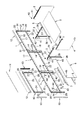
次に、添付図面に示した実施形態に基づき、本発明を更に詳細に説明する。図1は、本発明に係る間仕切パネルを用いてデスクを構成するパネルデスクシステムの構成部材を示す分解斜視図、図2〜図4はパネルデスクシステムの態様例を示し、図6〜図13はパネルデスクシステムの基本構成を示し、図14〜図20はオプション取付装置の具体例を示し、図中符号1はパネルフレーム、2は端部脚、3は支持脚、4はパネル脚、5は天板、6はダクトカバー、7は上部配線受け、8は下部配線受け、9は幕板、10は延長フレーム、11はパネル板、12は笠木、13は側カバーをそれぞれ示している。   Next, the present invention will be described in more detail based on the embodiments shown in the accompanying drawings. FIG. 1 is an exploded perspective view showing components of a panel desk system that constitutes a desk using a partition panel according to the present invention, FIGS. 2 to 4 show examples of the panel desk system, and FIGS. 14 to 20 show specific examples of the option mounting apparatus, in which 1 is a panel frame, 2 is an end leg, 3 is a support leg, 4 is a panel leg, and 5 is a panel leg. A top plate, 6 is a duct cover, 7 is an upper wiring receiver, 8 is a lower wiring receiver, 9 is a curtain plate, 10 is an extension frame, 11 is a panel plate, 12 is a headboard, and 13 is a side cover.

本実施形態に係るパネルデスクシステムは、図1に示すように、複数のパネルフレーム1,…を側方へ連結し、端部に位置する前記パネルフレーム1の縦枠14に前記端部脚2を取付けるとともに、中間に位置する前記パネルフレーム1の縦枠14に支持脚3,…を取付け、そして前記端部脚2と支持脚3の上位及び隣接する両側の支持脚3,3の上位に天板5を載置して固定する。前記天板5の後端と前記パネルフレーム1との間にダクト開口15を設けて、該ダクト開口15にダクトカバー6を開閉可能に設けている。また、前記ダクト開口15の下方で、前記パネルフレーム1の前面側に上部配線受け7と下部配線受け8とを取付け、その前面側に着脱可能且つ開閉可能に幕板9を取付けて配線装置を構成している。また、前記支持脚3には、必要に応じてパネル脚4を連結一体化し、あたかも端部脚2のように構成することも可能である。   In the panel desk system according to the present embodiment, as shown in FIG. 1, a plurality of panel frames 1,... Are connected laterally, and the end leg 2 is connected to the vertical frame 14 of the panel frame 1 located at the end. Are attached to the vertical frame 14 of the panel frame 1 positioned in the middle, and the upper ends of the end legs 2 and the supporting legs 3 and the upper supporting legs 3 and 3 on both adjacent sides. The top plate 5 is placed and fixed. A duct opening 15 is provided between the rear end of the top plate 5 and the panel frame 1, and a duct cover 6 is provided in the duct opening 15 so as to be openable and closable. An upper wiring receiver 7 and a lower wiring receiver 8 are attached to the front side of the panel frame 1 below the duct opening 15, and a curtain plate 9 is attached to the front side so as to be detachable and openable. It is composed. Further, if necessary, a panel leg 4 can be connected and integrated with the support leg 3 as if it were an end leg 2.

図2及び図3は、前記パネルフレーム1の両側に対称に天板5,5を配置した対面デスク態様を示している。本発明では、前記パネルフレーム1の高さは、その上端に笠木12を取付けた状態で、該笠木12の上面と前記天板5の上面とが略面一になるように設定されている。つまり、図2のように、前記パネルフレーム1の上端に笠木12を取付け、前記天板5の後端との間に設けたダクト開口15に前記ダクトカバー6を装着することにより、対面フラットデスク態様となる。また、図3のように、前記パネルフレーム1の上端に延長フレーム10を連結し、該延長フレーム10の表裏両面にパネル板11,11を取付けるとともに、該延長フレーム10の上端に笠木12、側端に側カバー13を取付けることにより、対面した天板5,5の中間に目隠し機能を有するフロントパネル部16を設けることができる。尚、前記パネルフレーム1の上端に笠木12を取付けた場合も、延長フレーム10とパネル板11とを取付けた場合も、前記ダクト開口15にはダクトカバー6を取付けることが可能である。尚、本発明は、このようなパネルデスクシステムのフロントパネル部16に限らず、一般の間仕切パネルにも適用できるものである。   2 and 3 show a facing desk form in which the top plates 5 and 5 are symmetrically arranged on both sides of the panel frame 1. In the present invention, the height of the panel frame 1 is set so that the upper surface of the headboard 12 and the upper surface of the top plate 5 are substantially flush with the headboard 12 attached to the upper end thereof. That is, as shown in FIG. 2, the headboard 12 is attached to the upper end of the panel frame 1, and the duct cover 6 is attached to the duct opening 15 provided between the rear end of the top plate 5 and the facing flat desk. It becomes an aspect. Further, as shown in FIG. 3, an extension frame 10 is connected to the upper end of the panel frame 1, panel panels 11 and 11 are attached to both the front and back surfaces of the extension frame 10, and the headboard 12 is connected to the upper end of the extension frame 10. By attaching the side cover 13 to the end, the front panel portion 16 having a blindfold function can be provided in the middle of the facing top plates 5 and 5. The duct cover 6 can be attached to the duct opening 15 both when the headboard 12 is attached to the upper end of the panel frame 1 and when the extension frame 10 and the panel plate 11 are attached. The present invention can be applied not only to the front panel portion 16 of such a panel desk system but also to a general partition panel.

次に、各部の詳細を説明する。前記パネルフレーム1は、図1、図6及び図12に示すように、両側に縦枠14,14を有し、両縦枠14,14の上端部間に上横枠17と下部間に下横枠18を縦枠14の下端部を余して固着した構造である。前記上横枠17と下横枠18の表裏方向の厚さは縦枠14よりも約5mm程度狭く設定し、該パネルフレーム1の両縦枠14,14の表面側に前記パネル板11を装着した際に、前記上横枠17及び下横枠18とパネル板11の裏面との間の隙間を利用してコードを配線できるようにしている。前記両縦枠14,14の下端には、高さ調節可能なアジャスター19,19を設けている。そして、両縦枠14,14の表裏両面には、前記パネル板11の背面両側上下部に突設した係合部を係合して取付けるための開口20,…を上下方向に所定ピッチで形成するとともに、上下部と中間部に左右一対の係止孔21,21を形成している。また、前記上横枠17と下横枠18の表裏両面で上縁に沿って横方向に一定間隔で横長の係合孔22,…を形成し、該係合孔22,…は上下パネル板11,11の間及びパネル板11の上端と笠木12の間の横目地部23に露出するようになっている(図3及び図4参照)。また、前記横目地部23に臨む縦枠14の端部にも横幅の狭い係合孔22を形成している。前記パネルフレーム1,1同士は、互いの縦枠14,14の端面を接合した状態で、貫通したボルトとナットで側方へ連結する。この連結構造は、間仕切パネルの連結構造と同じである。   Next, details of each part will be described. As shown in FIGS. 1, 6 and 12, the panel frame 1 has vertical frames 14 and 14 on both sides, and an upper horizontal frame 17 and a lower portion between the upper ends of the vertical frames 14 and 14 and the lower portion. In this structure, the horizontal frame 18 is fixed with the lower end portion of the vertical frame 14 remaining. The thickness of the upper horizontal frame 17 and the lower horizontal frame 18 in the front and back direction is set to be about 5 mm narrower than the vertical frame 14, and the panel plate 11 is mounted on the surface side of both vertical frames 14, 14 of the panel frame 1. In this case, the cords can be wired using the gaps between the upper horizontal frame 17 and the lower horizontal frame 18 and the back surface of the panel plate 11. At the lower ends of the vertical frames 14, 14, there are provided adjusters 19, 19 whose height can be adjusted. And, on both front and back surfaces of the vertical frames 14, 14, openings 20,... For engaging and mounting engaging portions projecting from the upper and lower portions on both sides of the back surface of the panel plate 11 are formed at a predetermined pitch in the vertical direction. In addition, a pair of left and right locking holes 21 and 21 are formed in the upper and lower parts and the middle part. Further, on the front and back surfaces of the upper horizontal frame 17 and the lower horizontal frame 18, horizontally long engagement holes 22,... Are formed at regular intervals along the upper edge, and the engagement holes 22,. 11 and 11 and the horizontal joint 23 between the upper end of the panel plate 11 and the headboard 12 is exposed (see FIGS. 3 and 4). Further, an engagement hole 22 having a narrow lateral width is also formed at the end of the vertical frame 14 facing the horizontal joint portion 23. The panel frames 1 and 1 are connected to each other with a penetrating bolt and nut while the end faces of the vertical frames 14 and 14 are joined to each other. This connection structure is the same as the connection structure of the partition panel.

前記延長フレーム10は、図1及び図12に示すように、両側の縦枠24,24の上端部間に上横枠25を固着するとともに、下端部間に下横枠26を固着し、該縦枠24には前記縦枠14と同様に開口20,…を形成し、上横枠25と縦枠24にも前記上横枠17と縦枠14と同様に係合孔22,…を形成している。更に、前記延長フレーム10の両縦枠24,24の下端には、前記パネルフレーム1の両縦枠14,14の上端開口に嵌合する嵌合部27,27を下方へ向けて延設している。そして、前記パネルフレーム1の上に延長フレーム10を連結するには、前記延長フレーム10の両嵌合部27,27をパネルフレーム1の両縦枠14,14の上端開口に嵌合するとともに、パネルフレーム1の上横枠17と延長フレーム10の下横枠26を接合した状態で上下方向にボルトとナットで締結する。図4には、前記延長フレーム10の高さが異なる2種類のものを用いて、段違いのフロントパネル部16を構成している。尚、前記延長フレーム10は、複数を上方へ積み重ねて連結することができ、所望の高さの間仕切パネルを構成できる。   As shown in FIGS. 1 and 12, the extension frame 10 has an upper horizontal frame 25 fixed between upper ends of vertical frames 24, 24 on both sides, and a lower horizontal frame 26 fixed between lower ends. Openings 20 are formed in the vertical frame 24 in the same manner as the vertical frame 14, and engagement holes 22 are formed in the upper horizontal frame 25 and the vertical frame 24 in the same manner as the upper horizontal frame 17 and the vertical frame 14. doing. Further, at the lower ends of the vertical frames 24, 24 of the extension frame 10, fitting portions 27, 27 that fit into the upper end openings of the vertical frames 14, 14 of the panel frame 1 are extended downward. ing. And in order to connect the extension frame 10 on the said panel frame 1, while fitting both the fitting parts 27 and 27 of the said extension frame 10 to the upper end opening of both the vertical frames 14 and 14 of the panel frame 1, The panel frame 1 is fastened with bolts and nuts in the vertical direction with the upper horizontal frame 17 and the lower horizontal frame 26 of the extension frame 10 joined. In FIG. 4, a front panel portion 16 having a different level is configured using two types of extension frames 10 having different heights. A plurality of the extension frames 10 can be stacked and connected upward, and a partition panel having a desired height can be configured.

本発明では、フレームの具体的構造については制限がなく、前述のように、パネルフレーム1の上に単数又は複数の延長フレーム10を連結して所定の高さのフレームを構成し、その少なくとも表面側に複数のパネル板11と上端の横枠に笠木12を取付けて構成し、前記パネル板11と笠木12との間及び上下のパネル板11,11間に横目地部23を形成し、該横目地部23に横枠の係合孔22,…が臨んでいればよいのである(図14参照)。最小構成は、前記パネルフレーム1のみを用い、一枚のパネル板11と上端の上横枠17に笠木12を装着する構成である。また、従来の間仕切パネルのように、所定高さの両側縦枠間に複数の横枠を固定した一体構造のフレームを用いてもよい。   In the present invention, the specific structure of the frame is not limited. As described above, one or a plurality of extension frames 10 are connected to the panel frame 1 to form a frame having a predetermined height, and at least the surface thereof. A plurality of panel plates 11 and a top frame 12 are attached to a top frame, and a horizontal joint portion 23 is formed between the panel plate 11 and the top plate 12 and between the top and bottom panel plates 11, 11, It is only necessary that the horizontal frame engagement holes 22,... Face the horizontal joint portion 23 (see FIG. 14). The minimum configuration is a configuration in which only the panel frame 1 is used, and the headboard 12 is mounted on one panel plate 11 and the upper horizontal frame 17 at the upper end. Moreover, you may use the frame of the integral structure which fixed the some horizontal frame between the vertical frames of both sides like the conventional partition panel.

図5には、多数のパネルフレーム1及び延長フレーム10を連結するとともに、パネル板11と笠木12及び側カバー13を装着し、あるいは部分的に高さの高い通常の間仕切パネルを連結して区画形成し、一部に端部脚2、支持脚3及び天板5を装着してデスク部を構成し、更に本発明のオプション取付装置を用いて間仕切パネルをT字状に連結した部分も有する複合的なパネルデスクシステムを示している。   In FIG. 5, a number of panel frames 1 and extension frames 10 are connected, and a panel plate 11, a headboard 12 and a side cover 13 are attached, or a normal partition panel having a partly high height is connected and partitioned. A desk part is formed by attaching the end leg 2, the support leg 3 and the top plate 5 to a part, and further, there is a part where the partition panel is connected in a T shape using the option mounting device of the present invention. A complex panel desk system is shown.

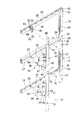
前記支持脚3は、図6及び図7に示すように、奥行幅が前記天板5よりも狭く前記パネルフレーム1の縦枠14の前面に沿って連結する脚板部28と、該脚板部28の上端から前方へ延び上位に前記天板5を取付ける支持アーム29とを有する逆L字形である。前記脚板部28の後端面には、前記縦枠14の下側二対の係止孔21,21に係止する下向きフック30,30を上下部に突設するとともに、後端部上部には脚連結金具31を受け入れ、上端後部から下方へ挿入した締結ボルト32で上方へ引き付けることができるようになっている。前記脚連結金具31は、図10に示すように、後側に前記縦枠14の最上方の一対の係止孔21,21に係止する上向きフック33,33を突設するとともに、上面板34に前記締結ボルト32を螺合する螺孔35を形成したものである。   As shown in FIGS. 6 and 7, the support leg 3 has a leg plate portion 28 that is narrower than the top plate 5 and is connected along the front surface of the vertical frame 14 of the panel frame 1, and the leg plate portion 28. It has an inverted L-shape having a support arm 29 that extends forward from the upper end of the upper plate and has the upper plate 5 attached to the upper side. On the rear end surface of the leg plate portion 28, downward hooks 30, 30 that are engaged with the two lower pairs of engagement holes 21, 21 of the vertical frame 14 protrude from the upper and lower portions, and on the upper portion of the rear end portion. The leg connecting bracket 31 is received and can be pulled upward by the fastening bolt 32 inserted downward from the rear end of the upper end. As shown in FIG. 10, the leg connecting bracket 31 projects upward hooks 33, 33 that are engaged with the pair of uppermost locking holes 21, 21 of the vertical frame 14 on the rear side, and an upper surface plate. 34 is formed with a screw hole 35 into which the fastening bolt 32 is screwed.

そして、前記支持脚3を前記パネルフレーム1の縦枠14に連結するには、先ず前記脚連結金具31の上向きフック33,33を前記縦枠14の最上方の係止孔21,21に係止した状態で、前記支持脚3の下向きフック30,30をそれぞれ下側二対の係止孔21,21に係止するとともに、前記脚連結金具31を脚板部28の上端部内に受け入れる。それから、前記脚板部28の上端の通孔から挿入した前記締結ボルト32を脚連結金具31の螺孔35に螺合し、該脚連結金具31を上方へ引き上げると、それに伴って前記支持脚3が下方へ押し下げられ、前記下向きフック30は下方へ、上向きフック33は上方へ力が加わるので、強固に連結される。ここで、前記支持脚3の脚板部28の下端には、高さ調節可能なアジャスター36を設けてあり、調節して床面に接地させる。   In order to connect the support leg 3 to the vertical frame 14 of the panel frame 1, first, the upward hooks 33, 33 of the leg connecting bracket 31 are engaged with the uppermost locking holes 21, 21 of the vertical frame 14. In the stopped state, the downward hooks 30, 30 of the support leg 3 are locked in the two lower pairs of locking holes 21, 21, respectively, and the leg connecting bracket 31 is received in the upper end portion of the leg plate portion 28. Then, the fastening bolt 32 inserted from the upper end through-hole of the leg plate portion 28 is screwed into the screw hole 35 of the leg connecting metal 31 and the leg connecting metal 31 is pulled upward. Is pushed downward, and the downward hook 30 is downwardly connected and the upward hook 33 is upwardly connected, so that they are firmly connected. Here, an adjuster 36 capable of adjusting the height is provided at the lower end of the leg plate portion 28 of the support leg 3, and is adjusted to be grounded on the floor surface.

図6及び図7は、前記パネルフレーム1の各縦枠14にそれぞれ前記支持脚3を連結する例であるが、図8及び図9に示すように、連結したパネルフレーム1,1の両縦枠14,14の接合線に一つの前記支持脚3の中心が位置するように取付けることも可能である。それにより、中間部に設ける支持脚3の数を少なくすることができる。図8に示すように、連結したパネルフレーム1,1の両縦枠14,14の同じ高さ位置に、4つの係止孔21,…が存在するので、中央側の二つの係止孔21,21を選んで、前記同様に脚連結金具31を用いて支持脚3を取付けるのである。つまり、隣接する各パネルフレーム1の縦枠14の外側の係止孔21を一対用いるのである。取付方法は、前記と全く同様である。   6 and 7 show examples in which the support legs 3 are connected to the vertical frames 14 of the panel frame 1, respectively. As shown in FIGS. 8 and 9, both vertical frames of the connected panel frames 1 and 1 are used. It is also possible to attach so that the center of one said support leg 3 is located in the joining line of the frames 14 and 14. FIG. Thereby, the number of the support legs 3 provided in the intermediate part can be reduced. As shown in FIG. 8, since there are four locking holes 21,... At the same height position of the vertical frames 14, 14 of the connected panel frames 1, 1, there are two locking holes 21 on the center side. , 21 is selected, and the support leg 3 is attached using the leg connecting bracket 31 in the same manner as described above. That is, a pair of locking holes 21 outside the vertical frame 14 of each adjacent panel frame 1 is used. The attachment method is exactly the same as described above.

そして、前記支持脚3の支持アーム29に前記天板5を載置して固定するには、前記支持アーム29上端前後部に固定板37,37を取付け、該固定板37を天板5の下面にネジ止めして固定する。前記固定板37は、中心とその両側等距離に通孔38,…を有し、パネルフレーム1の各縦枠14にそれぞれ支持脚3を取付ける場合には、一端部の通孔38を用いて内側に突出するように前記固定板37をネジ39で固定する(図6参照)。一方、連結したパネルフレーム1,1の互いに接合した縦枠14,14の中央に一つの支持脚3を取付ける場合には、中央の通孔38を用いて前記固定板37が両側に突出するように固定する。そして、前記天板5の両側部を支持脚3の上端に載置し、前記固定板37の残余の通孔38を用いてネジ止めする。尚、図11に示すように、前記端部脚2の上端前後部にも前記固定板37,37を内側へ突出するように固定し、同様に天板5をネジ止めする。   In order to place and fix the top plate 5 on the support arm 29 of the support leg 3, fixing plates 37 and 37 are attached to the front and rear ends of the upper end of the support arm 29, and the fixing plate 37 is attached to the top plate 5. Secure with screws on the bottom. The fixing plate 37 has through holes 38 at equal distances from the center and both sides thereof. When the support legs 3 are attached to the vertical frames 14 of the panel frame 1, the through holes 38 at one end are used. The fixing plate 37 is fixed with screws 39 so as to protrude inward (see FIG. 6). On the other hand, when one support leg 3 is attached to the center of the joined vertical frames 14 and 14 of the panel frames 1 and 1, the fixing plate 37 protrudes to both sides using the central through hole 38. Secure to. Then, both side portions of the top plate 5 are placed on the upper end of the support leg 3 and screwed using the remaining through holes 38 of the fixed plate 37. As shown in FIG. 11, the fixing plates 37 and 37 are fixed to the front and rear ends of the end leg 2 so as to protrude inward, and the top plate 5 is similarly screwed.

本実施形態では、図1に示すように、必要に応じて前記支持脚3の脚板部28の前方で前記支持アーム29と床面との間に、該支持アーム29と一体化するパネル脚4を着脱可能に取付けることができるようになっている。前記支持脚3にパネル脚4を連結した状態では、前記端部脚2と略同等な外形となる。   In this embodiment, as shown in FIG. 1, the panel leg 4 integrated with the support arm 29 between the support arm 29 and the floor surface in front of the leg plate portion 28 of the support leg 3 as required. Can be attached detachably. When the panel leg 4 is connected to the support leg 3, the outer shape is substantially the same as that of the end leg 2.

前記パネル脚4は、上端に前記支持アーム29を受け入れて前後方向にスライド係合するガイド溝40を形成するとともに、後端と前記脚板部28の前端とを互いに凹凸嵌合する嵌合構造とし、前記パネル脚4のガイド溝40に前記支持アーム29を係合するとともに、前記パネル脚4の後端を前記脚板部28の前端に凹凸嵌合した状態で、前記支持脚3とパネル脚4とを前後方向に締結手段で引き付けて連結する。   The panel leg 4 has a guide groove 40 that receives the support arm 29 at the upper end and slides in the front-rear direction, and has a fitting structure in which the rear end and the front end of the leg plate portion 28 are fitted to each other. The support leg 3 and the panel leg 4 are engaged with the support arm 29 engaged with the guide groove 40 of the panel leg 4 and the rear end of the panel leg 4 is ruggedly fitted to the front end of the leg plate portion 28. Are attracted and connected in the front-rear direction by fastening means.

ここで、図6及び図7に示したように、パネルフレーム1の各縦枠14にそれぞれ支持脚3を取付け、端部脚2と支持脚3及び両支持脚3,3の上位にそれぞれ天板5,…を取付けた場合には、特定の天板5とそれを支持していた支持脚3を他の天板5と支持脚3とに関係なく取り除くことができ、その取り除いた空間をミーティングスペース等の他の目的に使用できるように、態様を変更することが容易である。その場合、中間に位置していた支持脚3が端部に位置するようになると、足入れ空間を側方から隠蔽するために、前記パネル脚4を支持脚3に装着し、あたかも端部脚2のように変更するのである。   Here, as shown in FIGS. 6 and 7, the support legs 3 are respectively attached to the vertical frames 14 of the panel frame 1, and the end legs 2, the support legs 3, and the support legs 3, 3 are respectively positioned above the top legs. When the plates 5,... Are attached, the specific top plate 5 and the support legs 3 supporting the specific top plate 5 can be removed regardless of the other top plates 5 and the support legs 3, and the removed space can be removed. It is easy to change the aspect so that it can be used for other purposes such as a meeting space. In that case, when the support leg 3 located in the middle comes to be located at the end, the panel leg 4 is attached to the support leg 3 in order to conceal the foot space from the side, as if the end leg. It is changed like 2.

次に、図1、図11及び図13に基づいて、ダクトカバー取付装置について簡単に説明する。前記天板5は、後端と前記パネルフレーム1の上横枠17との間にダクト開口15を設けて、前記支持脚3の上端及び端部脚2の上端に取付けられ、該ダクト開口15に面する前記支持脚3と端部脚2の上端後部に取付部材41を取付け、そして該取付部材41に対して前記ダクトカバー6を回動開閉可能に支持するヒンジ部材42を前後方向の位置を変更可能に取付けている。前記取付部材41とヒンジ部材42は共に合成樹脂製である。   Next, the duct cover mounting device will be briefly described with reference to FIGS. 1, 11, and 13. The top plate 5 is provided with a duct opening 15 between the rear end and the upper horizontal frame 17 of the panel frame 1, and is attached to the upper end of the support leg 3 and the upper end of the end leg 2. A mounting member 41 is attached to the rear end of the upper end of the support leg 3 and the end leg 2 facing the front, and a hinge member 42 that supports the duct cover 6 so as to be capable of rotating and opening is attached to the mounting member 41 in the front-rear direction. Is installed to be changeable. Both the mounting member 41 and the hinge member 42 are made of synthetic resin.

次に、図1及び図13に基づいて、配線ダクト装置を簡単に説明する。前記ダクト開口15の下方の空間で、前記パネルフレーム1の上横枠17の前面側に前記上部配線受け7を取付けるとともに、下横枠18の前面側に下部配線受け8を取付け、更に両配線受けの前面側に前記幕板9を開閉可能且つ着脱可能に取付けて内部空間を形成し、前記上部配線受け7と下部配線受け8に収容した余剰コード、ケーブルが前方から見えないようにしている。具体的には、前記下横枠18の左右両側部に取付けた支持金具43,43で前記幕板9の下端を前後傾動可能に支持するとともに、前記天板5の下面両側部に取付けた係止金具44,44で前記幕板9の上部両側部に設けたラッチ45,45を係着して取付けている。尚、前記幕板9の前面側には、前記ラッチ45,45の操作部のみが露出している。   Next, the wiring duct device will be briefly described with reference to FIGS. 1 and 13. In the space below the duct opening 15, the upper wiring receiver 7 is attached to the front side of the upper horizontal frame 17 of the panel frame 1, and the lower wiring receiver 8 is attached to the front side of the lower horizontal frame 18. The curtain plate 9 is detachably attached to the front side of the receiver to form an internal space so that excess cords and cables accommodated in the upper wiring receiver 7 and the lower wiring receiver 8 cannot be seen from the front. . Specifically, the lower end of the curtain plate 9 is supported so as to be tiltable forward and backward by support brackets 43, 43 attached to the left and right sides of the lower horizontal frame 18, and attached to both sides of the lower surface of the top plate 5. Latches 45, 45 provided on both sides of the upper portion of the curtain plate 9 are fixedly attached to the clasps 44, 44. Note that only the operation portions of the latches 45 and 45 are exposed on the front side of the curtain plate 9.

本発明は、図14〜図16に示すように、前記横目地部23に臨んだ前記係合孔22,…を利用し、単数又は横並びの複数の係合孔22に係着金具46を係着し、該係着金具46を利用して他の間仕切パネル又は他の部品等のオプションを取付けるのである。具体的には、上下に位置する複数の横目地部23,…に臨む横枠の係合孔22,…に、それぞれ係着金具46,…を係着し、上下に位置する複数の係着金具46,…に渡って連結杆47を上下方向に取付けるとともに、該連結杆47を利用してオプションを取付けるのである。前記係着金具46は、互いに左右逆向きの係止爪53,58を有する第1フック金具48と第2フック金具49、及び前記第1フック金具48と第2フック金具49を一体化する本体金具50とからなり、前記第1フック金具48と第2フック金具49の各係止爪を同一の前記係合孔22にそれぞれ係止した状態で、前記本体金具50でネジ止め一体化する。   As shown in FIGS. 14 to 16, the present invention uses the engagement holes 22,... Facing the horizontal joint portion 23, and engages the engaging metal fittings 46 with a single or a plurality of side-by-side engagement holes 22. It is attached and options such as other partition panels or other parts are attached by using the engaging metal fitting 46. Specifically, the engaging metal fittings 46,... Are respectively engaged with the engaging holes 22,... Of the horizontal frame facing the plurality of horizontal joint portions 23,. A connecting rod 47 is mounted in the vertical direction across the metal fittings 46,... And an option is mounted using the connecting rod 47. The engaging metal fitting 46 has a first hook fitting 48 and a second hook fitting 49 having locking claws 53 and 58 that are opposite to each other in the left-right direction, and a main body that integrates the first hook fitting 48 and the second hook fitting 49. The main body metal 50 is integrated with screws with the engagement hooks of the first hook metal 48 and the second hook metal 49 being respectively engaged with the same engagement hole 22.

図17に基づいて、前記係着金具46を更に詳しく説明する。前記第1フック金具48は、垂直な長方形の基板51の上縁右半分に挿入片52を直角に形成し、該挿入片52の先端部には右側外向きに係止爪53を突設し、前記基板51の下縁には前記挿入片52と同じ方向に補強片54を折曲形成し、更に前記基板51の上下部に螺孔55,55を設けている。実際には、前記螺孔55は、前記基板51に通孔を形成し、該通孔の裏面側にナットを固着して設けている。   Based on FIG. 17, the engaging metal fitting 46 will be described in more detail. The first hook fitting 48 has an insertion piece 52 formed at a right angle on the right half of the upper edge of a vertical rectangular substrate 51, and a locking claw 53 is projected outward from the right end at the tip of the insertion piece 52. A reinforcing piece 54 is bent at the lower edge of the substrate 51 in the same direction as the insertion piece 52, and screw holes 55, 55 are provided at the upper and lower portions of the substrate 51. Actually, the screw hole 55 is formed by forming a through hole in the substrate 51 and fixing a nut to the back side of the through hole.

また、前記第2フック金具49は、前記基板51と同じ大きさの垂直な基板56の上縁左半分に挿入片57を直角に形成し、該挿入片57の先端部には左側外向きに係止爪58を突設し、前記基板56の上部に通孔59を形成するとともに、下部に座グリ孔60を形成している。   The second hook metal fitting 49 has an insertion piece 57 formed at a right angle on the upper left half of the vertical board 56 having the same size as the board 51, and the tip of the insertion piece 57 faces leftward outward. A locking claw 58 is protruded, a through hole 59 is formed in the upper part of the substrate 56, and a counterbore hole 60 is formed in the lower part.

また、前記本体金具50は、前記第1フック金具48の基板51と前記第2フック金具49の基板56を重ねた状態で収容できる断面略コ字形の取付部61と、該取付部61の上縁に直角に折曲形成した平面視略T字形のカバー片62を有し、前記取付部61で上側の螺孔55及び通孔59に対応する位置に座グリ孔63を形成するとともに、前記基板51,56と干渉しない下部に螺孔64を形成している。前記本体金具50の取付部61は、前記51,56よりも上下寸法が長い取付板65の両側に側面板66,66を折曲形成した構造である。   In addition, the main body metal fitting 50 includes a mounting portion 61 having a substantially U-shaped cross-section that can accommodate the substrate 51 of the first hook metal fitting 48 and the substrate 56 of the second hook metal fitting 49 in an overlapped manner, A cover piece 62 having a substantially T-shape in plan view bent at a right angle to the edge is formed, and a counterbore hole 63 is formed at a position corresponding to the upper screw hole 55 and the through hole 59 in the mounting portion 61. A screw hole 64 is formed in a lower portion that does not interfere with the substrates 51 and 56. The attachment part 61 of the main body metal fitting 50 has a structure in which side plates 66 and 66 are bent and formed on both sides of an attachment plate 65 whose vertical dimension is longer than those of the 51 and 56.

そして、図16及び図17(b)に示すように、前記第1フック金具48の挿入片52を横目地部23に挿入し、所望の係合孔22の右側孔縁に係止爪53を係止し、それから前記第2フック金具49の挿入片57を横目地部23に挿入し、同一の前記係合孔22の左側孔縁に係止爪58を係止し、両挿入片52,57を左右に並べるとともに、前記第1フック金具48の基板51と前記第2フック金具49の基板56を重ね、前記第2フック金具49の下方の座グリ孔60から挿入した皿ネジ67を前記第1フック金具48の下方の螺孔55に螺合して連結する。それから、前記本体金具50のカバー片62を前記両挿入片52,57の上側から前記横目地部23内に挿入するとともに、重なった状態の前記第1フック金具48の基板51と前記第2フック金具49の基板56を前記本体金具50の取付部61の溝内部に収容し、該取付部61の上部に設けた座グリ孔63に挿入した皿ネジ68を前記第2フック金具49の通孔59を通して前記第1フック金具48の上側の螺孔55に螺合し、前記第1フック金具48と第2フック金具49を一体化する。   Then, as shown in FIGS. 16 and 17 (b), the insertion piece 52 of the first hook metal fitting 48 is inserted into the horizontal joint 23, and the locking claw 53 is attached to the right hole edge of the desired engagement hole 22. Then, the insertion piece 57 of the second hook metal fitting 49 is inserted into the horizontal joint portion 23, the locking claw 58 is locked to the left hole edge of the same engagement hole 22, and both the insertion pieces 52, 57 are arranged side by side, the substrate 51 of the first hook metal fitting 48 and the substrate 56 of the second hook metal fitting 49 are overlapped, and the countersunk screws 67 inserted from the counterbored holes 60 below the second hook metal fitting 49 are The first hook fitting 48 is screwed into and connected to the screw hole 55 below. Then, the cover piece 62 of the main body metal fitting 50 is inserted into the horizontal joint portion 23 from the upper side of the both insertion pieces 52 and 57, and the substrate 51 and the second hook of the first hook metal fitting 48 in an overlapped state. The board 56 of the metal fitting 49 is accommodated in the groove of the attachment portion 61 of the main metal fitting 50, and a countersunk screw 68 inserted into a counterbore hole 63 provided in the upper portion of the attachment portion 61 is passed through the second hook metal fitting 49. 59, the first hook metal fitting 48 and the second hook metal fitting 49 are integrated.

この状態で、前記第1フック金具48の挿入片52と前記第2フック金具49の挿入片57が前記係合孔22の孔内を埋めるように挿入され、またそれぞれの先端部に設けた両係止爪53,58が前記係合孔22の両側孔縁に係止しているので、該係合孔22から抜けることも、横方向に変位することもないのである。そして、前記係着金具46を前述のように係合孔22に係着した状態では、前記本体金具50のカバー片62の先端部が前記横目地部23内に埋没した状態となり、対応する上横枠17、下横枠18又は上横枠24に当接し、パネル面外方向の変位を規制し、また両挿入片52,57の上下移動を規制するとともに、前記カバー片62の首部は両挿入片52,57に重なって隠蔽し、更に取付部61の両側面板66,66の端縁は前記パネル板11の表面に当接する。前記パネル板11が存在せず、つまり横目地部23が形成されてなくても、横枠に係合孔22が形成されていれば、前記係着金具46を係着することが可能であるので、係着金具46を係着するのみにおいては、パネル板11及び横目地部23の存在は必須ではない。しかし、パネル板11が存在しないと間仕切パネルとしての機能はないので、本発明においては、パネル板11と横目地部23は前提として必要になる。また、前記係着金具46は、上下反転させて使うことも可能であり、図16の下側の係着金具46は上方の二つとは上下逆に使用した例である。   In this state, the insertion piece 52 of the first hook metal fitting 48 and the insertion piece 57 of the second hook metal fitting 49 are inserted so as to fill the hole of the engagement hole 22, and both of the two provided at the respective tip portions are provided. Since the locking claws 53 and 58 are locked to the both side hole edges of the engagement hole 22, they do not come out of the engagement hole 22 and are not displaced laterally. When the engagement fitting 46 is engaged with the engagement hole 22 as described above, the tip end portion of the cover piece 62 of the body fitting 50 is buried in the horizontal joint portion 23, and the corresponding upper Abutting on the horizontal frame 17, the lower horizontal frame 18 or the upper horizontal frame 24, the displacement of the panel surface outward direction is restricted, the vertical movement of both the insertion pieces 52, 57 is restricted, and the neck portion of the cover piece 62 is both The insertion pieces 52 and 57 are overlapped and concealed, and the end edges of both side plates 66 and 66 of the mounting portion 61 abut against the surface of the panel plate 11. Even if the panel plate 11 does not exist, that is, the horizontal joint portion 23 is not formed, the engaging metal fitting 46 can be engaged if the engaging hole 22 is formed in the horizontal frame. Therefore, the presence of the panel plate 11 and the horizontal joint portion 23 is not indispensable only for engaging the engaging metal fitting 46. However, if the panel plate 11 is not present, there is no function as a partition panel. Therefore, in the present invention, the panel plate 11 and the horizontal joint portion 23 are necessary. In addition, the engaging metal fitting 46 can be used upside down, and the lower engaging metal fitting 46 in FIG. 16 is used upside down with respect to the upper two.

そして、前記連結杆47は、図16に示すように、断面略コ字形の長尺部材であり、前記本体金具50の取付部61を収容できる凹溝部69を有するとともに、該凹溝部69と反対側の表面には上下に複数のナット部材70,…を突設している。ここで、前記ナット部材70,…の位置は、前記パネルフレーム1及びその上に延長フレーム10,…を連結した状態で、側方へ他のパネルフレーム1及延長フレーム10を連結する際に、縦枠14,14同士、あるいは縦枠24,24同士を左右に貫通したボルト、ナットで連結する位置と一致させている。   As shown in FIG. 16, the connecting rod 47 is a long member having a substantially U-shaped cross section, and has a concave groove portion 69 that can accommodate the attachment portion 61 of the main body metal fitting 50, and is opposite to the concave groove portion 69. A plurality of nut members 70,. Here, the positions of the nut members 70,... Are when the other panel frame 1 and the extension frame 10 are connected to the side with the panel frame 1 and the extension frames 10,. The vertical frames 14 and 14 or the vertical frames 24 and 24 are made to coincide with the positions where they are connected by bolts and nuts penetrating left and right.

そして、このように上下の複数の横目地部23,…に臨んだ係合孔22,…を用いて、前記係着金具46,…を係着した後、前記連結杆47の凹溝部69に各本体金具50の取付部61を収容した状態で、該連結杆47に形成した通孔71,…から挿入したネジ72を前記本体金具50の螺孔64に螺合して、複数の係着金具46,…と連結杆47を一体化する。このように、間仕切パネルの前面側で横方向中間部に沿って、前記連結杆47が垂直に保持される。この連結杆47に、間仕切パネルのフレームの縦枠を接合し、ボルト73をナット部材70に螺合して連結する(図5、図20参照)。尚、図中符号74は、最下段の設けた巾木を示している。従って、パネルフレーム1に取付けたパネル板11と巾木74の間にも横目地部23が形成され、同様に下横枠18に形成した係合孔22,…が臨んでいる。前記巾木74をパネルフレーム1に装着しなくても、つまり横目地部23が形成されてなくても、係合孔22を用いて前記係着金具46を係着することが可能であり、その場合には前記係着金具46を上下反転させて本体金具50の取付部61がパネル板11の表面に当接する方が、取付状態が安定するので好ましい。当然ではあるが、前記係着金具46を単独で特定の係合孔22に係着し、小さな物品を装着することも可能である。   Then, after engaging the engaging metal fittings 46,... Using the engaging holes 22, facing the plurality of upper and lower horizontal joint portions 23,. In a state in which the mounting portion 61 of each main body metal fitting 50 is accommodated, a screw 72 inserted from a through hole 71 formed in the connecting rod 47 is screwed into the screw hole 64 of the main body metal fitting 50, and a plurality of engagements are made. The metal fittings 46,... And the connecting rod 47 are integrated. In this way, the connecting rod 47 is held vertically along the lateral intermediate portion on the front side of the partition panel. The vertical frame of the frame of the partition panel is joined to the connecting rod 47, and the bolt 73 is screwed to the nut member 70 to be connected (see FIGS. 5 and 20). In the figure, reference numeral 74 denotes a baseboard provided at the lowest level. Accordingly, a horizontal joint portion 23 is also formed between the panel plate 11 attached to the panel frame 1 and the baseboard 74, and the engagement holes 22,. Even if the baseboard 74 is not attached to the panel frame 1, that is, even if the horizontal joint portion 23 is not formed, the engaging metal fitting 46 can be engaged using the engagement hole 22. In that case, it is preferable that the attachment metal plate 50 is turned upside down so that the attachment portion 61 of the main body metal plate 50 comes into contact with the surface of the panel plate 11 because the attachment state becomes stable. Needless to say, it is also possible to attach a small article by attaching the engaging metal fitting 46 to the specific engaging hole 22 alone.

次に、間仕切パネルの表面側の横方向端部に、即ち前記パネルフレーム1の縦枠14及び延長フレーム10の縦枠24の前面側にオプションを取付けるには、スペース的に前述の係着金具46を用いることができない。これは、前記パネルフレーム1の縦枠14及び延長フレーム10の縦枠24の上端部には、他の延長フレーム10の縦枠24の下端に設けた嵌合部27が挿入されるため、内部に突出させることができず、そのため前記縦枠14及び縦枠24の横目地部23に臨む端部に設けた係合孔22は、パネルフレーム1の上横枠17、下横枠18及び延長フレーム10の上横枠25に形成した係合孔22より横幅が狭く、しかも外側端に位置するからである。このような端部にも取付けることが可能な係着金具75を図18及び図19に示している。   Next, in order to attach an option to the lateral end of the front surface side of the partition panel, that is, to the front side of the vertical frame 14 of the panel frame 1 and the vertical frame 24 of the extension frame 10, the above-mentioned engaging metal fittings are spatially used. 46 cannot be used. This is because the fitting portion 27 provided at the lower end of the vertical frame 24 of the other extension frame 10 is inserted into the upper end portions of the vertical frame 14 of the panel frame 1 and the vertical frame 24 of the extension frame 10. Therefore, the engagement hole 22 provided at the end of the vertical frame 14 and the vertical frame 24 facing the horizontal joint 23 is provided with the upper horizontal frame 17, the lower horizontal frame 18 and the extension of the panel frame 1. This is because the lateral width is narrower than the engagement hole 22 formed in the upper lateral frame 25 of the frame 10 and is positioned at the outer end. An anchor fitting 75 that can be attached to such an end is shown in FIGS.

図18及び図19に示した係着金具75は、前記第1フック金具76と第2フック金具77の各係止爪を横並びの異なる前記係合孔22,22にそれぞれ係止した状態で、前記本体金具50でネジ止め一体化するものである。つまり、この係着金具75にも前述と同じ本体金具50を用いる。本実施形態において、前述の実施形態と同一構成には、同一符号を付してその説明は省略する。   In the state where the engaging metal fitting 75 shown in FIG. 18 and FIG. 19 is engaged with the engaging holes 22 and 22 of the first hook metal fitting 76 and the second hook metal fitting 77 which are respectively engaged with the engaging holes 22 and 22 which are different from each other. The body fitting 50 is integrated with screws. That is, the same main metal fitting 50 as described above is also used for the engaging metal fitting 75. In the present embodiment, the same components as those of the above-described embodiment are denoted by the same reference numerals, and the description thereof is omitted.

図18及び図19(a)に示すように、前記第1フック金具76は、垂直な長方形の基板51の上縁右半分に平面視L字形の挿入片78を直角に形成し、該挿入片78の先端部には左側内向きに係止爪79を形成し、前記基板51の下縁には前記挿入片78と同じ方向に補強片54を折曲形成し、更に前記基板51の上下部に螺孔55,55を設けている。本実施形態の前記挿入片78は、前記挿入片52と同様な挿入部78Aと該挿入部78Aから右側へ直角に延長したアーム部78Bとからなっており、該アーム部78Bの先端側に前記挿入部78Aの方へ向けて前記係止爪79を形成している。   As shown in FIGS. 18 and 19 (a), the first hook fitting 76 has an L-shaped insertion piece 78 formed on the right half of the upper edge of the vertical rectangular substrate 51 at right angles, and the insertion piece. A locking claw 79 is formed at the front end of 78 inwardly on the left side, and a reinforcing piece 54 is bent at the lower edge of the substrate 51 in the same direction as the insertion piece 78. Are provided with screw holes 55, 55. The insertion piece 78 of the present embodiment is composed of an insertion portion 78A similar to the insertion piece 52 and an arm portion 78B extending rightward from the insertion portion 78A to the right side. The locking claw 79 is formed toward the insertion portion 78A.

また、前記第2フック金具77は、前記基板51と同じ大きさの垂直な基板56の上縁左半分に挿入片80を直角に形成し、該挿入片80の先端部には右側内向きに係止爪81を形成し、前記基板56の上部に通孔59を形成するとともに、下部に座グリ孔60を形成している。本実施形態の前記挿入片80は、前記挿入片57と同様な挿入部80Aと該挿入部80Aから左側へ直角に延長したアーム部80Bとからなっており、該アーム部80Bの先端側に前記挿入部80Aの方へ向けて前記係止爪81を形成している。   The second hook fitting 77 has an insertion piece 80 formed at a right angle on the left half of the upper edge of the vertical substrate 56 having the same size as the substrate 51, and the tip of the insertion piece 80 faces rightward inward. A locking claw 81 is formed, a through hole 59 is formed in the upper part of the substrate 56, and a counterbore hole 60 is formed in the lower part. The insertion piece 80 of the present embodiment is composed of an insertion portion 80A similar to the insertion piece 57 and an arm portion 80B extending from the insertion portion 80A to the left at a right angle. The locking claw 81 is formed toward the insertion portion 80A.

ここで、前記第2フック金具77のアーム部80Bは、前記第1フック金具76のアーム部78Bよりも短く設定している。そして、前記第1フック金具76の挿入片78を横目地部23に挿入するとともに、端部から2番目の係合孔22、即ち上横枠17,25の端部の係合孔22の左側孔縁(間仕切パネルにおいて外側)に前記係止爪79を係止し、それから前記第2フック金具77の挿入片80を横目地部23に挿入するとともに、端部の係合孔22、即ち縦枠14,24の係合孔22の右側孔縁(間仕切パネルにおいて内側)に前記係止爪81を係止し、前記第1フック金具76の基板51に前記第2フック金具77の基板56を重ねて皿ネジ67で締め付け、両基板51,56を前記本体金具50の取付部61の溝内部に収容し、皿ネジ68で一体化する。この状態では、前記本体金具50は、前記係止爪81に近い位置、即ち縦枠14,24の前面側の位置になる。そして、前記同様に、上下に複数の係着金具75,…を係着した状態で、前記連結杆47の凹溝部69に各本体金具50の取付部61を収容した状態で、該連結杆47をネジ72で締め付けて、複数の係着金具75,…と連結杆47を一体化するのである。   Here, the arm portion 80B of the second hook metal fitting 77 is set to be shorter than the arm portion 78B of the first hook metal fitting 76. And while inserting the insertion piece 78 of the said 1st hook metal fitting 76 in the horizontal joint part 23, the left side of the engagement hole 22 of the 2nd engagement hole 22, ie, the edge part of the upper horizontal frames 17 and 25, from an edge part. The locking claw 79 is locked to the hole edge (outside of the partition panel), and then the insertion piece 80 of the second hook metal fitting 77 is inserted into the horizontal joint 23 and the engagement hole 22 at the end, that is, the vertical The locking claw 81 is locked to the right hole edge (inner side of the partition panel) of the engagement holes 22 of the frames 14 and 24, and the substrate 56 of the second hook fitting 77 is attached to the substrate 51 of the first hook fitting 76. The two substrates 51, 56 are accommodated in the groove of the mounting portion 61 of the main body metal 50 and integrated with the countersunk screws 68. In this state, the body fitting 50 is located at a position close to the locking claw 81, that is, a position on the front side of the vertical frames 14 and 24. In the same manner as described above, the connecting rods 47 are attached in the state in which the attaching portions 61 of the main body fittings 50 are accommodated in the concave groove portions 69 of the connecting rods 47 with the plurality of engaging brackets 75 attached vertically. Are tightened with a screw 72 to integrate the plurality of engagement fittings 75,...

尚、前記第1フック金具76と第2フック金具77は、上下反転させて使用することはできない。そのため、前記第1フック金具76と第2フック金具77と鏡像関係となる形状の第1フック金具76Aと第2フック金具77Aを用意しておくのである。図示した例では、間仕切パネルの左側の端部に、前記第1フック金具76と第2フック金具77を装着したが、右側の端部では前記第1フック金具76Aと第2フック金具77Aを用いる必要がある。   The first hook fitting 76 and the second hook fitting 77 cannot be used upside down. Therefore, the first hook fitting 76A and the second hook fitting 77A having a mirror image relation with the first hook fitting 76 and the second hook fitting 77 are prepared. In the illustrated example, the first hook fitting 76 and the second hook fitting 77 are attached to the left end of the partition panel, but the first hook fitting 76A and the second hook fitting 77A are used at the right end. There is a need.

これまでの実施形態では、オプションとして他の間仕切パネルを連結する構造を説明したが、棚板、照明器具あるいはキャビネットを前記係着金具46を用いて取付けることができる。例えば、棚板については、同一の横目地部23内において左右方向に所定間隔を隔てて存する任意の係合孔22,22に対して係着金具46,46を各々係着し、係着金具46を利用してブラケットを取付け、あるいは、左右に位置する複数の係着金具46,…に渡って横方向に延びる連結杆を取付け、連結杆を利用してブラケットを取付け、これらブラケットに棚板を支持することができる。   In the embodiments described so far, the structure for connecting other partition panels as an option has been described. However, a shelf board, a lighting fixture, or a cabinet can be attached by using the engagement fitting 46. For example, with respect to the shelf board, the engagement metal fittings 46 and 46 are respectively engaged with the arbitrary engagement holes 22 and 22 existing at a predetermined interval in the left and right direction within the same horizontal joint portion 23, and the engagement metal fittings. 46 is attached to the bracket, or a connecting rod extending in the lateral direction across the plurality of engaging metal fittings 46 located on the left and right is attached, and the bracket is attached using the connecting rod, and the shelf is attached to these brackets. Can be supported.

次に、図21〜図26に基づいて、前記天板5の上面に、サイドパネル82を前記フロントパネル部16の横目地部23を利用して取付ける構造を説明する。前記サイドパネル82を取付ける位置は横方向で任意ではないが、前記横目地部23に臨む係合孔22,…の何れかの位置に対応するので、実質的に略希望通りの位置に取付けることができる。先ず、前記サイドパネル82は、側面視四角形のサイドフレーム83の表裏両面にパネル板84,84を着脱可能に装着するとともに、サイドフレーム83の上端に笠木85、前後端面に化粧カバー86,86を取付けた構造である。   Next, a structure in which the side panel 82 is attached to the top surface of the top plate 5 using the horizontal joint portion 23 of the front panel portion 16 will be described with reference to FIGS. The position where the side panel 82 is attached is not arbitrary in the lateral direction, but corresponds to any position of the engagement holes 22 facing the horizontal joint portion 23, so that the side panel 82 is attached at a substantially desired position. Can do. First, the side panel 82 is detachably mounted with panel plates 84 and 84 on both the front and back sides of a side frame 83 that is square when viewed from the side, the headboard 85 is attached to the upper end of the side frame 83, and the decorative covers 86 and 86 are attached to the front and rear end faces. It is an attached structure.

そして、図21に示すように、前記天板5の上面に奥行方向に沿ってレール部材87を前後のクランプ金具88,89で取付け、該レール部材87に前記サイドフレーム83の下枠90に設けた下方開放の係合溝91を嵌合して互いにネジ止めするとともに、前記係合孔22に前方から嵌挿した規制金具92を、後方の化粧カバー86の上端に固定した側面視倒L字状の連結金具93の水平板93Aと重ねた状態で、前記サイドフレーム83より後方へ延びた前記笠木85の後端部下面側にネジ止めし、前記サイドフレーム83を天板5とフロントパネル部16に取付ける。最後に、前記サイドフレーム83にパネル板84を装着して、前後左右の変位を確実に規制した状態でサイドパネル82を天板5の上面に構築する。   Then, as shown in FIG. 21, a rail member 87 is attached to the upper surface of the top plate 5 along the depth direction by front and rear clamp fittings 88 and 89, and is provided on the lower frame 90 of the side frame 83 on the rail member 87. A side-view side-down L-shape, in which a fitting fitting 91 that is opened downward is fitted and screwed together, and a restriction fitting 92 that is inserted into the engagement hole 22 from the front is fixed to the upper end of the rear decorative cover 86. In the state where it is overlapped with the horizontal plate 93 </ b> A of the connecting bracket 93, the side frame 83 is screwed to the lower surface side of the rear end portion of the headboard 85 extending rearward from the side frame 83, and the side frame 83 is attached to the top plate 5 and the front panel portion 16 is attached. Finally, the panel plate 84 is attached to the side frame 83, and the side panel 82 is constructed on the top surface of the top plate 5 in a state where the displacement in the front-rear and left-right directions is reliably regulated.

更に詳しくは、図22及び図23に示すように、前記レール部材87は、断面略ハット型のであり、中央のレール部87Aを上方に向けて、両側の支持板87B,87Bを前記天板5の上面に直接、又は好ましくは緩衝シートを介して載置する。そして、図25及び図26に示すように、前記天板5の前側から前クランプ金具88の当止板88Aを天板下面に係止するとともに、前記レール部材87のレール部87の内部に引付板88Bを位置させ、前記レール部87の上方から挿通したネジ88Cを前記引付板88Bに螺合して前記前クランプ金具88を上方へ引き上げて前記天板5を上下から挟持する。同様に、前記前記天板5の後側から後クランプ金具89の当止板89Aを天板下面に係止するとともに、前記レール部材87のレール部87の内部に引付板89Bを位置させ、前記レール部87の上方から挿通したネジ89Cを前記引付板89Bに螺合して前記後クランプ金具89を上方へ引き上げて前記天板5を上下から挟持する。それから、前記サイドフレーム83の下枠90の係合溝91を、前記レール部材87のレール部87に外嵌し、前記下枠90の上方から挿通したネジ94を前記レール部87に螺合して取付ける。   More specifically, as shown in FIGS. 22 and 23, the rail member 87 has a substantially hat-shaped cross section, the central rail portion 87A faces upward, and the support plates 87B and 87B on both sides are placed on the top plate 5. It is mounted directly on the upper surface of the sheet, or preferably via a buffer sheet. Then, as shown in FIGS. 25 and 26, the stopper plate 88A of the front clamp fitting 88 is locked to the bottom surface of the top plate 5 from the front side of the top plate 5 and is pulled inside the rail portion 87 of the rail member 87. The attaching plate 88B is positioned, the screw 88C inserted from above the rail portion 87 is screwed into the attaching plate 88B, and the front clamp fitting 88 is pulled upward to sandwich the top plate 5 from above and below. Similarly, the retaining plate 89A of the rear clamp fitting 89 is engaged with the bottom surface of the top plate 5 from the rear side of the top plate 5, and the attracting plate 89B is positioned inside the rail portion 87 of the rail member 87, A screw 89C inserted from above the rail portion 87 is screwed into the pulling plate 89B, and the rear clamp fitting 89 is pulled upward to clamp the top plate 5 from above and below. Then, the engaging groove 91 of the lower frame 90 of the side frame 83 is externally fitted to the rail portion 87 of the rail member 87, and a screw 94 inserted from above the lower frame 90 is screwed to the rail portion 87. And install.

一方、前記サイドフレーム83の上端後部は、図22〜図24に示すように、左右への変位を規制するだけでよいので、前記規制金具92の後端の嵌合片92Aを所望の係合孔22に前方から嵌入し、該規制金具92を前記サイドフレーム83に前記連結金具93を介して、後側の化粧カバー86及び笠木85を利用して連結するのである。具体的には、前記連結金具93の垂直板93Bを後側の前記化粧カバー86の上端部内面側に水平板93Aを後方へ突出させた状態で、ネジ93Cで固定する。ぞじて、前記後側の前記化粧カバー86を前記サイドフレーム83の後端に取付ける。それから、前記規制金具92の嵌合片92Aを係合孔22に嵌入し、前記連結金具93の水平板93Aの下側に重ね、前記サイドフレーム83の上端に後部を後方へ突出した状態で取付けた前記笠木85の下面側に、前記規制金具92と連結金具93の水平板93Aを共にネジ95で連結するのである。尚、図24に示すように、前記規制金具92、連結金具93、化粧カバー86及び笠木85は、予め前記サイドフレーム83に取付けた状態で、後方に突出した嵌合片92Aを係合孔22に嵌入すると同時に、前記サイドフレーム83の下枠90の係合溝91を、前記レール部材87のレール部87に外嵌してネジ止めするようにしてもよい。   On the other hand, as shown in FIGS. 22 to 24, the upper end rear portion of the side frame 83 only needs to restrict the displacement to the left and right, so that the fitting piece 92A at the rear end of the restricting bracket 92 can be engaged with a desired one. The restriction fitting 92 is inserted into the hole 22 from the front, and is connected to the side frame 83 through the connecting fitting 93 by using the rear decorative cover 86 and the headboard 85. Specifically, the vertical plate 93B of the connection fitting 93 is fixed with screws 93C in a state where the horizontal plate 93A protrudes rearward on the inner surface side of the upper end of the decorative cover 86 on the rear side. In other words, the decorative cover 86 on the rear side is attached to the rear end of the side frame 83. Then, the fitting piece 92A of the restricting metal fitting 92 is fitted into the engaging hole 22, and is attached to the lower side of the horizontal plate 93A of the connecting metal piece 93, with the rear portion protruding rearward from the upper end of the side frame 83. Further, the restriction metal 92 and the horizontal plate 93A of the connection metal 93 are both connected to the lower surface side of the headboard 85 with screws 95. As shown in FIG. 24, the restricting fitting 92, the connecting fitting 93, the decorative cover 86, and the headboard 85 are fitted to the side frame 83 in advance, and the fitting piece 92A protruding rearward is inserted into the engaging hole 22 as shown in FIG. At the same time, the engaging groove 91 of the lower frame 90 of the side frame 83 may be externally fitted to the rail portion 87 of the rail member 87 and screwed.

図22は、前記延長フレーム10の端部の係合孔22を用いて、天板5の端部にサイドパネル82を取付ける態様であり、その場合には、前記規制金具92の嵌合片92Aを外側端に設けた形状のものを用いる。一方、図23は、前記延長フレーム10の中間部の係合孔22を用いて、天板5の左右中間部にサイドパネル82を取付ける態様であり、その場合には、前記規制金具92の嵌合片92Aを中央部に設けた形状のものを用いる。   FIG. 22 shows an aspect in which the side panel 82 is attached to the end portion of the top plate 5 using the engagement hole 22 at the end portion of the extension frame 10, and in this case, the fitting piece 92 </ b> A of the restriction fitting 92 is used. The thing of the shape which provided in the outer side end is used. On the other hand, FIG. 23 shows an aspect in which the side panel 82 is attached to the left and right intermediate portions of the top plate 5 using the engagement holes 22 in the intermediate portion of the extension frame 10. A shape in which the joining piece 92A is provided in the central portion is used.

1 パネルフレーム、 2 端部脚、
3 支持脚、 4 パネル脚、
5 天板、 6 ダクトカバー、
7 上部配線受け、 8 下部配線受け、
9 幕板、 10 延長フレーム、
11 パネル板、 12 笠木、
13 側カバー、 14 縦枠、
15 ダクト開口、 16 フロントパネル部、
17 上横枠、 18 下横枠、
19 アジャスター、 20 開口、
21 係止孔、 22 係合孔、
23 横目地部、 24 縦枠、
25 上横枠、 26 下横枠、
27 嵌合部、 28 脚板部、
29 支持アーム、 30 下向きフック、
31 脚連結金具、 32 締結ボルト、
33 上向きフック、 34 上面板、
35 螺孔、 36 アジャスター、
37 固定板、 38 通孔、
39 ネジ、 40 ガイド溝、
41 取付部材、 42 ヒンジ部材、
43 支持金具、 44 係止金具、
45 ラッチ、 46 係着金具、
47 連結杆、 48 第1フック金具、
49 第2フック金具、 50 本体金具、
51 基板、 52 挿入片、
53 係止爪、 54 補強片、
55 螺孔、 56 基板、
57 挿入片、 58 係止爪、
59 通孔、 60 座グリ孔、
61 取付部、 62 カバー片、
63 座グリ孔、 64 螺孔、
65 取付板、 66 側面板、
67 皿ネジ、 68 皿ネジ、
69 凹溝部、 70 ナット部材、
71 通孔、 72 ネジ、
73 ボルト、 74 巾木、
75 係着金具、 76 第1フック金具、
76A 第1フック金具、 77 第2フック金具、
77A 第2フック金具、 78 挿入片、
78A 挿入部、 78B アーム部、
79 係止爪、 80 挿入片、
80A 挿入部、 80B アーム部、
81 係止爪、 82 サイドパネル、
83 サイドフレーム、 84 パネル板、
85 笠木、 86 化粧カバー、
87 レール部材、 87A レール部、
87B 支持板、 88 前クランプ金具、
88A 当止板、 88B 引付板、
88C ネジ、 89 後クランプ金具、
89A 当止板、 89B 引付板、
89C ネジ、 90 下枠、
91 係合溝、 92 規制金具、
92A 嵌合片、 93 連結金具、
93A 水平板、 93B 垂直板、
93C ネジ、 94 ネジ、
95 ネジ。
1 panel frame, 2 end legs,
3 support legs, 4 panel legs,
5 Top plate, 6 Duct cover,
7 Upper wiring receptacle, 8 Lower wiring receptacle,
9 curtains, 10 extension frames,
11 Panel board, 12 Kasagi,
13 side cover, 14 vertical frame,
15 Duct opening, 16 Front panel,
17 Upper horizontal frame, 18 Lower horizontal frame,
19 adjusters, 20 openings,
21 engagement hole, 22 engagement hole,
23 horizontal joint, 24 vertical frame,
25 Upper horizontal frame, 26 Lower horizontal frame,
27 fitting part, 28 leg plate part,
29 support arm, 30 downward hook,
31 leg fittings, 32 fastening bolts,
33 upward hook, 34 top plate,
35 screw holes, 36 adjusters,
37 fixing plate, 38 through hole,
39 screws, 40 guide grooves,
41 mounting member, 42 hinge member,
43 support brackets, 44 locking brackets,
45 Latch, 46 Anchor bracket,
47 connecting rod, 48 first hook fitting,
49 Second hook metal fitting, 50 Main metal fitting,
51 substrate, 52 insertion piece,
53 locking claws, 54 reinforcing pieces,
55 screw holes, 56 substrates,
57 Insertion piece, 58 Locking claw,
59 through holes, 60 counterbore holes,
61 mounting part, 62 cover piece,
63 counterbore hole, 64 screw hole,
65 mounting plate, 66 side plate,
67 countersunk screws, 68 countersunk screws,
69 concave groove, 70 nut member,
71 through holes, 72 screws,
73 bolts, 74 baseboards,
75 anchor fittings, 76 first hook fittings,
76A first hook bracket, 77 second hook bracket,
77A Second hook metal fitting, 78 Insertion piece,
78A insertion part, 78B arm part,
79 Claw, 80 Insertion piece,
80A insertion part, 80B arm part,
81 locking claws, 82 side panels,
83 side frames, 84 panel boards,
85 Kasagi, 86 Makeup cover,
87 rail member, 87A rail part,
87B Support plate, 88 Front clamp bracket,
88A stop plate, 88B pulling plate,
88C screw, 89 Rear clamp fitting,
89A stop plate, 89B pulling plate,
89C screw, 90 lower frame,
91 engaging groove, 92 restricting bracket,
92A fitting piece, 93 coupling bracket,
93A horizontal plate, 93B vertical plate,
93C screw, 94 screw,
95 screws.

Claims (3)

フレームの少なくとも表面側に複数のパネル板と上端に笠木を取付け、前記パネル板と笠木との間及び上下のパネル板間に横目地部を形成し、この上下に複数の横目地部を備えた間仕切パネルに、該横目地部を利用して他の間仕切パネル又は他の部品を取付けることが可能な間仕切パネルにおけるオプション取付装置において、前記横目地部に臨む前記フレームに横方向に所定間隔で複数の係合孔を形成し、上下に位置する複数の横目地部の単数又は横並びの複数の係合孔にそれぞれ係着金具を係着し、上下に位置する複数の係着金具に渡って連結杆を上下方向に取付けるとともに、該連結杆を利用してオプションを取付けることを特徴とする間仕切パネルにおけるオプション取付装置。 A plurality of panel plates are attached to at least the surface side of the frame and a headboard is attached to the upper end, a horizontal joint portion is formed between the panel plate and the headboard and between the upper and lower panel plates, and a plurality of horizontal joint portions are provided on the upper and lower sides. plurality partition panel, the option attachment device that prevails partition panel to mount the other partition panel or other components by utilizing the lateral joint portion, at predetermined intervals in the lateral direction in the frame facing the horizontal joint portions Are formed, and engaging metal fittings are respectively attached to a single or a plurality of horizontal engaging holes in a plurality of horizontal joints positioned above and below, and connected across a plurality of vertical engaging metal fittings. An option mounting device for a partition panel , wherein the scissors are attached in the vertical direction and the options are attached using the connecting scissors . 両側の縦枠間に複数の横枠を備えたフレームの少なくとも表面側に、上下に複数のパネル板を装着するとともに、上端の横枠に笠木を装着し、前記横目地部に臨む横枠及び縦枠に形成した前記係合孔に前記係着金具を係着してなる請求項1記載の間仕切パネルにおけるオプション取付装置。 At least on the surface side of the frame having a plurality of horizontal frame between opposite sides of the vertical frame, with mounting a plurality of panel board up and down, horizontal frame fitted with a coping next frame of the upper end, facing the horizontal joint portions and optional mounting device in partition panel of the-engaging bracket to the engaging hole formed in the vertical frame engaging wear and formed by claim 1. 前記係着金具は、互いに左右逆向きの係止爪を有する第1フック金具と第2フック金具、及び前記第1フック金具と第2フック金具を一体化する本体金具とからなり、前記第1フック金具と第2フック金具の各係止爪を同一の前記係合孔又は横並びの異なる前記係合孔にそれぞれ係止した状態で、前記本体金具でネジ止め一体化してなる請求項1又は2記載の間仕切パネルにおけるオプション取付装置。 The engagement fitting includes a first hook fitting and a second hook fitting having locking claws that are opposite to each other in the left-right direction, and a body fitting that integrates the first hook fitting and the second hook fitting. in a state where the respective engaging claws sealed respectively engaged with the same engaging hole or the engagement hole of side-by-side different hook brackets and the second hook fitting, formed by screws integral with the main body metal fitting according to claim 1 or 2 Optional mounting device for the described partition panel.
JP2011022688A 2011-02-04 2011-02-04 Optional mounting device for partition panel Active JP5724419B2 (en)

Priority Applications (1)

Application Number Priority Date Filing Date Title
JP2011022688A JP5724419B2 (en) 2011-02-04 2011-02-04 Optional mounting device for partition panel

Applications Claiming Priority (1)

Application Number Priority Date Filing Date Title
JP2011022688A JP5724419B2 (en) 2011-02-04 2011-02-04 Optional mounting device for partition panel

Publications (2)

Publication Number Publication Date
JP2012161406A JP2012161406A (en) 2012-08-30
JP5724419B2 true JP5724419B2 (en) 2015-05-27

Family

ID=46841452

Family Applications (1)

Application Number Title Priority Date Filing Date
JP2011022688A Active JP5724419B2 (en) 2011-02-04 2011-02-04 Optional mounting device for partition panel

Country Status (1)

Country Link
JP (1) JP5724419B2 (en)

Family Cites Families (5)

* Cited by examiner, † Cited by third party
Publication number Priority date Publication date Assignee Title
US5890325A (en) * 1996-08-22 1999-04-06 Steelcase Inc. Reconfigurable system for subdividing building space and having minimal footprint
JP3421750B2 (en) * 1999-08-31 2003-06-30 コクヨ株式会社 Panel equipment
JP2004019197A (en) * 2002-06-14 2004-01-22 Kokuyo Co Ltd Joint material
JP4360104B2 (en) * 2003-02-28 2009-11-11 コクヨ株式会社 Furniture unit
JP4470674B2 (en) * 2004-09-29 2010-06-02 コクヨ株式会社 Article support structure

Also Published As

Publication number Publication date
JP2012161406A (en) 2012-08-30

Similar Documents

Publication Publication Date Title
JP2005517841A (en) Panel system
US20080224579A1 (en) Modular storage system
JP5720277B2 (en) Wiring duct device in panel desk system
JP5724419B2 (en) Optional mounting device for partition panel
JP2012162879A (en) Attachment device for partition panel
JP2006204679A (en) Top board supporting structure
JP5724420B2 (en) Desk with light fixture
JP5214874B2 (en) Panel-like object mounting structure
JP2008079784A (en) Desk with side panel
JP6163764B2 (en) Table wiring duct equipment
JP2010106624A (en) Locking device, and t-shaped connecting device for partition panel using the same
JP5540999B2 (en) Side panel mounting device
JP2010125015A (en) Desk panel and mounting structure for the same
JP5630386B2 (en) Desk divider
JP5923855B2 (en) Top plate support device at desk
WO2012063737A1 (en) Room divider structure
JP5275405B2 (en) Desk leg equipment
JP2564823Y2 (en) Desktop side panel mounting structure
JP2004016402A (en) Fixing device for shelf board
JP2012161404A (en) Duct cover attaching device in desk
AU2014274729A1 (en) Support bracket and screen and assemblies and accessories for the use therewith
JPH052106Y2 (en)
JP2004121694A (en) Knockdown desk system
JP5262832B2 (en) Desk panel mounting structure
JP2004016403A (en) Device for attaching light to shelf board

Legal Events

Date Code Title Description
A621 Written request for application examination

Free format text: JAPANESE INTERMEDIATE CODE: A621

Effective date: 20131227

A977 Report on retrieval

Free format text: JAPANESE INTERMEDIATE CODE: A971007

Effective date: 20140609

A131 Notification of reasons for refusal

Free format text: JAPANESE INTERMEDIATE CODE: A131

Effective date: 20140701

A521 Written amendment

Free format text: JAPANESE INTERMEDIATE CODE: A523

Effective date: 20140820

TRDD Decision of grant or rejection written
A01 Written decision to grant a patent or to grant a registration (utility model)

Free format text: JAPANESE INTERMEDIATE CODE: A01

Effective date: 20150303

A61 First payment of annual fees (during grant procedure)

Free format text: JAPANESE INTERMEDIATE CODE: A61

Effective date: 20150316

R150 Certificate of patent or registration of utility model

Ref document number: 5724419

Country of ref document: JP

Free format text: JAPANESE INTERMEDIATE CODE: R150

S531 Written request for registration of change of domicile

Free format text: JAPANESE INTERMEDIATE CODE: R313531

R350 Written notification of registration of transfer

Free format text: JAPANESE INTERMEDIATE CODE: R350