JP6163764B2 - Table wiring duct equipment - Google Patents

Table wiring duct equipment Download PDF

Info

Publication number
JP6163764B2
JP6163764B2 JP2013007804A JP2013007804A JP6163764B2 JP 6163764 B2 JP6163764 B2 JP 6163764B2 JP 2013007804 A JP2013007804 A JP 2013007804A JP 2013007804 A JP2013007804 A JP 2013007804A JP 6163764 B2 JP6163764 B2 JP 6163764B2
Authority
JP
Japan
Prior art keywords
duct
locking
support legs
plate
leg
Prior art date
Legal status (The legal status is an assumption and is not a legal conclusion. Google has not performed a legal analysis and makes no representation as to the accuracy of the status listed.)
Expired - Fee Related
Application number
JP2013007804A
Other languages
Japanese (ja)
Other versions
JP2014113437A (en
Inventor
貴司 小笠原
貴司 小笠原
潤 堀川
潤 堀川
Current Assignee (The listed assignees may be inaccurate. Google has not performed a legal analysis and makes no representation or warranty as to the accuracy of the list.)
Itoki Corp
Original Assignee
Itoki Corp
Priority date (The priority date is an assumption and is not a legal conclusion. Google has not performed a legal analysis and makes no representation as to the accuracy of the date listed.)
Filing date
Publication date
Application filed by Itoki Corp filed Critical Itoki Corp
Priority to JP2013007804A priority Critical patent/JP6163764B2/en
Publication of JP2014113437A publication Critical patent/JP2014113437A/en
Application granted granted Critical
Publication of JP6163764B2 publication Critical patent/JP6163764B2/en
Expired - Fee Related legal-status Critical Current
Anticipated expiration legal-status Critical

Links

Images

Landscapes

  • Tables And Desks Characterized By Structural Shape (AREA)

Description

本発明は、テーブルの配線ダクト装置に係わり、更に詳しくは床面から天板下へ配線するためのテーブルの配線ダクト装置に関するものである。   The present invention relates to a wiring duct device for a table, and more particularly to a wiring duct device for a table for wiring from a floor surface to below a top plate.

従来から、複数の天板を連設し、端部に位置する天板の外側端おいて棒脚あるいは脚板で支持するとともに、天板の連結部においては中間脚で支持した構造のテーブルは各種提供されている。また、天板の下面周縁部にビーム部材を配置して天板を補強するとともに、コーナー部でビーム部材に連結した脚ブラケットに棒脚を固定する基本構造も公知である。   Conventionally, a plurality of top plates are connected in series and supported by a rod leg or a leg plate at the outer end of the top plate located at the end, and various tables with a structure supported by an intermediate leg at the connecting portion of the top plate are available. Is provided. Further, a basic structure is known in which a beam member is disposed on the peripheral edge of the lower surface of the top plate to reinforce the top plate, and a rod leg is fixed to a leg bracket connected to the beam member at a corner portion.

また、床面から天板下へ配線するための縦ダクトを備えたテーブルも公知である。特に、天板を支持する脚部にダクト機能を設けたものも各種提供されている。例えば、特許文献1には、天板を支持する両支柱間にダクトパネルを取付け、床面からケーブルをダクトパネルに設けた配線ダクトを通して天板に開口した挿通孔から引き出す構造が開示されている。また、特許文献2には、天板を支持する支持脚にカバー取付け材を取付け、該カバー取付け材に対してカバー部材を係脱可能に取付け、カバー部材内部を配線スペースとして使用する配線ダクト装置が開示されている。ここで、特許文献2では、床面から引き出したケーブルを空中に露出した状態で、カバー部材の下端部から内部に引き込み、天板の下面に導く使用例が示されている。   A table having a vertical duct for wiring from the floor surface to below the top plate is also known. In particular, various types of leg portions that support the top plate are provided with a duct function. For example, Patent Document 1 discloses a structure in which a duct panel is attached between both columns supporting a top plate, and a cable is drawn from a floor surface through a wiring duct provided in the duct panel and from an insertion hole opened in the top plate. . Patent Document 2 discloses a wiring duct device in which a cover attachment member is attached to a support leg that supports the top plate, the cover member is detachably attached to the cover attachment member, and the inside of the cover member is used as a wiring space. Is disclosed. Here, Patent Document 2 shows a usage example in which a cable drawn from the floor surface is exposed in the air and drawn into the inside from the lower end of the cover member and led to the lower surface of the top plate.

また、脚部に配線ダクトを設けたものではないが、特許文献3には、自立可能な台脚の上端に配線ボックスをその接続用コンセントを上面に向けて設けるとともに、表裏両面にカバー部材を取付けて内部に上下方向のダクト空間を形成し、該ダクト空間の内部に複数のケーブル受けを設けた配線収納装置が開示され、前後に配置した机の天板の縁部に形成した切り込み部から前記配線ボックスを臨ませて使用する使用形態が開示されている。   Moreover, although the wiring duct is not provided in the leg part, in Patent Document 3, the wiring box is provided at the upper end of the stand leg that can stand on its own with the connection outlet facing the upper surface, and the cover member is provided on both the front and back sides. A wiring storage device is disclosed in which a vertical duct space is formed inside and a plurality of cable receivers are provided inside the duct space, and a notch formed at the edge of the top plate of the desk arranged at the front and rear is disclosed. A usage pattern in which the wiring box is used is disclosed.

何れの特許文献に記載の配線ダクト装置も床面から引き出したケーブルを天板下まで導くことができるが、床面から引き出したケーブルが配線ダクト装置の真下に位置することは稀であるので、殆どの場合がケーブルは一旦露出することになる。ケーブルが床面近くに露出していると、目障りであるばかりでなく、ケーブルに足を引っ掛けるといった不慮の事故が発生する恐れがある。   The wiring duct device described in any patent document can guide the cable drawn from the floor surface to the bottom of the top plate, but it is rare that the cable drawn from the floor surface is located directly below the wiring duct device. In most cases, the cable will be exposed once. If the cable is exposed near the floor, not only is it unsightly, but there is a risk of accidents such as getting caught in the cable.

特開2000−125946号公報JP 2000-125946 A 特開2005−131281号公報JP-A-2005-131281 特開2001−135949号公報JP 2001-135949 A

そこで、本発明が前述の状況に鑑み、解決しようとするところは、テーブルの脚に配線機能を持たせるとともに、床面から引き出したケーブルをテーブルの配置に係わらず外部に露出することなく天板下まで導くことが可能なテーブルの配線ダクト装置を提供する点にある。   Therefore, in view of the above situation, the present invention intends to solve the problem that the table leg is provided with a wiring function, and the cable drawn from the floor surface is not exposed to the outside regardless of the arrangement of the table. It is the point which provides the wiring duct apparatus of the table which can be led to the bottom.

本発明は、前述の課題解決のために、複数の天板を横方向に連設し、該天板を支持する中間脚に配線用の縦ダクトを設けてなるテーブルにおいて、前記中間脚は、間隔を隔てて配置した一対の支脚を備え、前記縦ダクトは、前記中間脚の両支脚を取り囲むように、平面視略コ字形の一対のダクトカバーを対向配置し、前記両支脚の外側側面に、前記ダクトカバーの両端縁部を係着手段にて着脱可能且つ取付位置を側方へ変更可能に係着し、両支脚及び1対のダクトカバーで縦方向に連続したダクト空間が形成されたことを特徴とするテーブルの配線ダクト装置を構成した(請求項1)。 In order to solve the above-mentioned problems, the present invention provides a table in which a plurality of top plates are connected in a horizontal direction, and a vertical duct for wiring is provided on an intermediate leg that supports the top plate . A pair of support legs arranged at intervals is provided, and the vertical duct has a substantially U-shaped pair of duct covers facing each other so as to surround both support legs of the intermediate leg, and on the outer side surfaces of the both support legs. The both ends of the duct cover are detachably attached by the engaging means and the attachment position can be changed to the side, and a duct space continuous in the vertical direction is formed by both the supporting legs and the pair of duct covers. A wiring duct device for a table characterized by the above is constructed (claim 1).

ここで、前記係着手段として、前記ダクトカバーの両端縁部の内側と前記両支脚の外側側面の一方にマグネット又は係合爪を設け、他方にスチール板等の吸着面又は係合孔を形成し、前記マグネットを吸着面に吸着し又は係合爪を係合孔に係止してダクトカバーを係着してなることが好ましい(請求項2)。   Here, as the engaging means, a magnet or an engaging claw is provided on one of the inner side of both end edges of the duct cover and the outer side surface of the both support legs, and an adsorption surface or an engaging hole such as a steel plate is formed on the other side. Preferably, the magnet is attracted to the attracting surface, or the engaging claw is engaged with the engaging hole and the duct cover is engaged.

また、前記中間脚は、テーブルの奥行方向の前後両側に間隔を隔てて一対の支脚を配置し、両支脚の上端間に上向き開放した断面コ字形の支持杆を渡設するとともに、下部間に連結杆を連結してなることも好ましい(請求項3)。 In addition, the intermediate leg has a pair of support legs arranged on both sides in the depth direction of the table with a space therebetween, and a U-shaped support rod opened upward between the upper ends of both support legs, and between the lower parts. It is also preferable to connect the connecting rods (claim 3).

更に、前記縦ダクトは、中間脚の両支脚の間に、上段コード受けを前記支持杆に吊止部材を用いて吊り下げ状に設けるとともに、下段コード受けを高さ調節可能に設け、更に前記中間脚と上段コード受け及び下段コード受けを取り囲むように一対のダクトカバーを、両支脚の外側側面に係着手段にて取付けてなることがより好ましい(請求項4)。   Further, the vertical duct is provided with an upper cord receiver suspended between the supporting legs of the intermediate leg by using a suspension member on the support rod, and a lower cord receiver is provided so that the height can be adjusted. More preferably, a pair of duct covers are attached to the outer side surfaces of both support legs by engaging means so as to surround the intermediate leg, the upper stage cord receiver and the lower stage cord receiver.

また、前記係着手段として、前記両支脚の内側面に複数の係止部を設けた係止金具を、該係止部が支脚の端面から突出するように取付け、前記ダクトカバーの内面両側部に設けた補強部材に前記係止金具の係止部に係止する係止孔若しくは係止凹部を設け、前記係止金具の支脚への取付姿勢に応じて前記ダクトカバーの取付位置を変化させてなることも好ましい(請求項5)。 Further, as the engaging means, a locking bracket provided with a plurality of locking portions on the inner side surfaces of the both supporting legs is attached so that the locking portions protrude from the end surfaces of the supporting legs, and both side portions on the inner surface of the duct cover The reinforcing member provided on the door is provided with a locking hole or a locking recess for locking to the locking portion of the locking bracket , and the mounting position of the duct cover is changed according to the mounting posture of the locking bracket on the support leg. It is also preferable (claim 5).

そして、前記中間脚は、両側に板状の支脚を平行に配置し、両支脚間を複数のコード受けで連結し一体化し、該支脚の上端に天板を支持する中間アームの中央部と固定する凹部を設けてなることがより好ましい(請求項6)。 Then, the intermediate leg is disposed parallel to the plate-shaped support leg on either side, between both support legs integrally coupled by a plurality of code received, and the central portion of the intermediate arm supporting the top plate to the upper end of said supporting leg More preferably, a recessed portion to be fixed is provided.

以上にしてなる請求項1に係る発明のテーブルの配線ダクト装置は、複数の天板を横方向に連設し、該天板を支持する中間脚に配線用の縦ダクトを設けてなるテーブルにおいて、前記中間脚は、間隔を隔てて配置した一対の支脚を備え、前記縦ダクトは、前記中間脚の両支脚を取り囲むように、平面視略コ字形の一対のダクトカバーを対向配置し、前記両支脚の外側側面に、前記ダクトカバーの両端縁部を係着手段にて着脱可能且つ取付位置を側方へ変更可能に係着し、両支脚及び1対のダクトカバーで縦方向に連続したダクト空間が形成されたので、床面からケーブルを引き出す位置が前記中間脚の位置からずれた場合に、前記ダクトカバーを側方へ付け替えて前記縦ダクトの空間内にケーブル引き出し位置を取り込むことができ、もってケーブルを露出することなく床面から天板下へ導くことができる。 The wiring duct device for a table of the invention according to claim 1 as described above is a table in which a plurality of top plates are connected in the horizontal direction, and a vertical duct for wiring is provided on an intermediate leg that supports the top plate . The intermediate leg includes a pair of support legs disposed at a distance from each other, and the vertical duct includes a pair of substantially U-shaped duct covers in plan view so as to surround both support legs of the intermediate leg , Both end edges of the duct cover are attached to the outer side surfaces of both support legs by attachment means so that the attachment position can be changed to the side, and the both ends of the support and the pair of duct covers are connected in the vertical direction. Since the duct space is formed, when the position where the cable is pulled out from the floor surface deviates from the position of the intermediate leg, the duct cover is changed to the side and the cable pull-out position is taken into the space of the vertical duct. You can It can be guided to the lower top plate from the floor surface without exposing the Buru.

請求項2によれば、前記係着手段として、前記ダクトカバーの両端縁部の内側と前記両支脚の外側側面の一方にマグネット又は係合爪を設け、他方にスチール板等の吸着面又は係合孔を形成し、前記マグネットを吸着面に吸着し又は係合爪を係合孔に係止してダクトカバーを係着してなるので、ダクトカバーの支脚への着脱が容易であるとともに、マグネットを用いた場合、吸着面の範囲内であれば取付位置の変更も任意あるいは多段階にでき、また係合爪と係合孔を用いる場合、少なくとも最小と最大の2箇所に設ければ付け替えることができ、通常の状態での縦ダクトの空間を必要最小限の大きさにすることができる。   According to a second aspect of the present invention, as the engaging means, a magnet or an engaging claw is provided on one of the inner side of both end edges of the duct cover and the outer side surface of the both support legs, and the other is an adsorption surface or engaging surface such as a steel plate. Forming a joint hole, attracting the magnet to the attracting surface or locking the engaging claw to the engaging hole and engaging the duct cover, it is easy to attach and detach the duct cover to the support leg, If a magnet is used, the mounting position can be changed arbitrarily or in multiple stages within the range of the attracting surface. When using an engagement claw and an engagement hole, it can be replaced if it is provided at least at the minimum and maximum two locations. The space of the vertical duct in a normal state can be made as small as necessary.

請求項3によれば、前記中間脚は、テーブルの奥行方向の前後両側に間隔を隔てて一対の支脚を配置し、両支脚の上端間に上向き開放した断面コ字形の支持杆を渡設するとともに、下部間に連結杆を連結してなるので、天板の支持に供する中間脚に構造的な制約を設けずに一対のダクトカバーを装着するだけで縦ダクトを構成できる。 According to a third aspect of the present invention, the intermediate leg has a pair of supporting legs arranged at intervals on both the front and rear sides in the depth direction of the table, and a U-shaped support rod having an upward opening is provided between the upper ends of the both supporting legs. At the same time, since the connecting rod is connected between the lower portions, the vertical duct can be configured only by mounting a pair of duct covers without providing structural restrictions on the intermediate leg for supporting the top plate.

請求項4によれば、前記縦ダクトは、中間脚の両支脚の間に、上段コード受けを前記支持杆に吊止部材を用いて吊り下げ状に設けるとともに、下段コード受けを高さ調節可能に設け、更に前記中間脚と上段コード受け及び下段コード受けを取り囲むように一対のダクトカバーを、両支脚の外側側面に係着手段にて取付けてなるので、縦ダクトのダクト空間内に大容量のケーブル収納部が設けられ、余剰ケーブルを収容することができるので、床面にケーブルがはみ出す心配がない。   According to a fourth aspect of the present invention, the vertical duct is provided with an upper cord receiver suspended between the support legs of the intermediate leg using a suspension member on the support rod, and the height of the lower cord receiver can be adjusted. In addition, a pair of duct covers are attached to the outer side surfaces of both support legs by engaging means so as to surround the intermediate leg, the upper cord receiver and the lower cord receiver, so that a large capacity is provided in the duct space of the vertical duct. Since the cable storage portion is provided and the excess cable can be stored, there is no fear that the cable protrudes from the floor surface.

請求項5によれば、前記係着手段として、前記両支脚の内側面に複数の係止部を設けた係止金具を、該係止部が支脚の端面から突出するように取付け、前記ダクトカバーの内面両側部に設けた補強部材に前記係止金具の係止部に係止する係止孔若しくは係止凹部を設け、前記係止金具の支脚への取付姿勢に応じて前記ダクトカバーの取付位置を変化させてなるので、簡単な構造によりダクトカバーの取付位置を多段階に変更することができ、またダクトカバーの支持状態も安定である。 According to a fifth aspect of the present invention, as the engaging means, an engaging metal fitting provided with a plurality of engaging portions on the inner side surfaces of the both support legs is attached so that the engaging portions protrude from the end surfaces of the support legs, and the duct The reinforcing member provided on both inner side surfaces of the cover is provided with a locking hole or a locking recess for locking to the locking portion of the locking metal , and the duct cover is provided in accordance with the mounting posture of the locking metal to the support leg. Since the mounting position is changed, the mounting position of the duct cover can be changed in multiple stages with a simple structure, and the support state of the duct cover is stable.

請求項6によれば、前記中間脚は、両側に板状の支脚を平行に配置し、両支脚間を複数のコード受けで連結し一体化し、該支脚の上端に天板を支持する中間アームの中央部と固定する凹部を設けてなるので、中間脚の構造が単純になりコスト低減化に寄与する。 According to claim 6, wherein the intermediate leg, midway parallel arranged a plate-shaped support leg on either side, between both support legs integrally coupled by a plurality of code receiving, supporting the top plate to the upper end of said supporting leg Since the concave portion to be fixed to the central portion of the arm is provided, the structure of the intermediate leg is simplified and contributes to cost reduction.

本発明に係るテーブルの全体斜視図である。1 is an overall perspective view of a table according to the present invention. 同じくテーブルの部分底面図である。It is a partial bottom view of the same table. ファンクションエッジの部分斜視図である。It is a fragmentary perspective view of a function edge. 天板の端縁部にファンクションエッジを設けた状態の部分縦断面図である。It is a fragmentary longitudinal cross-sectional view of a state in which a function edge is provided on the edge of the top plate. 中間脚と縦ダクトの構造を示す部分分解斜視図である。It is a partial exploded perspective view which shows the structure of an intermediate leg and a vertical duct. 中間アームと中間ブラケットを示す部分平面図である。It is a fragmentary top view which shows an intermediate | middle arm and an intermediate | middle bracket. 同じく中間アームと中間ブラケットを示す斜視図である。It is a perspective view which similarly shows an intermediate arm and an intermediate bracket. ファンクションエッジの連結部の構造を示す部分分解斜視図である。It is a partial exploded perspective view which shows the structure of the connection part of a function edge. 同じくファンクションエッジの連結部の構造を示す部分底面図である。It is a partial bottom view which similarly shows the structure of the connection part of a function edge. テーブルのコーナー部の構造を示す分解斜視図である。It is a disassembled perspective view which shows the structure of the corner part of a table. 脚ブラケットの周りの構造を示す分解斜視図である。It is a disassembled perspective view which shows the structure around a leg bracket. 同じく脚ブラケットの周りの構造を示す分解平面図である。It is a disassembled plan view which similarly shows the structure around a leg bracket. 天板の連結部の構造を示す一部省略した部分平面図である。It is the partial top view which abbreviate | omitted partially which shows the structure of the connection part of a top plate. 縦ダクトの構造を示し、通常の状態の部分平面図である。It is a partial plan view of a normal state showing the structure of a vertical duct. 縦ダクトの構造を示し、一方のダクトカバーを外側にずらせて係着してダクト空間を拡張した状態の部分平面図である。FIG. 4 is a partial plan view showing a structure of a vertical duct, in which one duct cover is shifted outward and engaged to expand a duct space. アクセスフロアと中間脚及び縦ダクトの位置関係を示し、通常の状態で縦ダクトを利用できる場合の説明用平面図である。It is a top view for explanation in case the vertical duct can be used in the normal state, showing the positional relationship between the access floor, the intermediate leg and the vertical duct. アクセスフロアと中間脚及び縦ダクトの位置関係を示し、一方のダクトカバーを外側にずらせて係着してダクト空間を拡張した状態で縦ダクトを利用する場合の説明用平面図である。It is a top view for description in the case of using a vertical duct in the state which showed the positional relationship of an access floor, an intermediate leg, and a vertical duct, and extended the duct space by shifting and engaging one duct cover outside. ファンクションエッジの係止レール部を利用して接続ユニットを取付けた状態の部分縦断面図である。It is a fragmentary longitudinal cross-sectional view of the state which attached the connection unit using the latching rail part of a function edge. 接続ユニットの一部省略した全体斜視図である。It is the whole perspective view which a part of connection unit was omitted. ファンクションエッジの係止レール部を利用して接続ユニットを取付けた状態を一部省略して示した部分正面図である。It is the partial front view which abbreviate | omitted and showed the state which attached the connection unit using the latching rail part of a function edge. ファンクションエッジの他の実施形態を示す部分縦断面図である。It is a fragmentary longitudinal cross-section which shows other embodiment of a function edge. 縦ダクトの他の実施形態を示し、ダクトカバーを支脚に最も接近させて支持した状態の縦ダクトの簡略縦断面図である。It is a simplified longitudinal cross-sectional view of the vertical duct of the state which showed other embodiment of the vertical duct and supported the duct cover closest to the support leg. 同じく縦ダクトの平面図である。It is a top view of a longitudinal duct similarly. ダクトカバーの部分側面図である。It is a partial side view of a duct cover. 係止金具の斜視図である。It is a perspective view of a locking metal fitting. 同じく縦ダクトの部分拡大縦断面図である。It is a partial enlarged vertical sectional view of a vertical duct. ダクトカバーを支脚から離して支持した状態の縦ダクトの平面図である。It is a top view of the vertical duct of the state which supported the duct cover away from the support leg. 同じく縦ダクトの部分拡大縦断面図である。It is a partial enlarged vertical sectional view of a vertical duct. 縦ダクトの更に他の実施形態を示し、ダクトカバーを支脚に最も接近させて支持した状態の縦ダクトの簡略縦断面図である。FIG. 10 is a simplified vertical sectional view of a vertical duct in a state in which still another embodiment of the vertical duct is shown and the duct cover is supported by being closest to the support leg. 同じく縦ダクトの平面図である。It is a top view of a longitudinal duct similarly. ダクトカバーの部分側面図である。It is a partial side view of a duct cover. 係止金具の斜視図である。It is a perspective view of a locking metal fitting. ダクトカバーを支脚から離して支持した状態の縦ダクトの部分拡大縦断面図である。It is a partial expanded longitudinal cross-sectional view of the vertical duct of the state which supported the duct cover apart from the support leg.

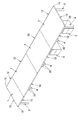
次に、添付図面に示した実施形態に基づき、本発明を更に詳細に説明する。図1は本発明に係るテーブルの全体斜視図、図2〜図12はその詳細を示し、図中符号1は天板、2は棒脚、3は中間脚、4は縦ダクト、5はキャビネットをそれぞれ示している。   Next, the present invention will be described in more detail based on the embodiments shown in the accompanying drawings. FIG. 1 is an overall perspective view of a table according to the present invention, and FIGS. 2 to 12 show details thereof. In the figure, reference numeral 1 is a top plate, 2 is a rod leg, 3 is an intermediate leg, 4 is a vertical duct, and 5 is a cabinet. Respectively.

本発明に係るテーブルの全体構成は、図1及び図2に示すように、複数の天板1,…を連設し、端部に位置する天板1の外側端おいて棒脚2,2で支持するとともに、天板1,1の連結部においては中間脚3で支持し、該中間脚3は縦ダクト4の一部を構成している。前記天板1,…の下方空間はフットフリー、ワゴンフリーとなっており、棒脚2以外のどの位置でも着座することができ、また引出し付きのキャビネット5を自由に配置することができ、前記縦ダクト4の前面側にも配置できるようになっている。   As shown in FIGS. 1 and 2, the overall structure of the table according to the present invention is a series of a plurality of top plates 1,..., And rod legs 2, 2 at the outer end of the top plate 1 located at the end. Are supported by intermediate legs 3 at the connecting portions of the top plates 1 and 1, and the intermediate legs 3 constitute a part of the vertical duct 4. The space below the top plate 1, ... is foot-free and wagon-free, and can be seated at any position other than the rod leg 2, and the cabinet 5 with drawers can be freely arranged, It can also be arranged on the front side of the vertical duct 4.

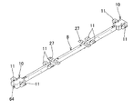
前記棒脚2は、図2及び図11に示すように、脚ブラケット6を介して天板1の下面に取付けられ、両脚ブラッケト6,6間にエンドアーム7を連結している。前記中間脚3は、図2及び図5に示すように、上端に中間アーム8が側面視略T字状に取付けられ、該中間アーム8は天板1,1の連結部に沿って配置されている。そして、隣接する前記中間脚3,3の上端間には、図2及び図5に示すように、ファンクションビーム9,9が間隔を置いて平行に連結され、更に前記エンドアーム7の中間部と中間脚3の上端間にもファンクションビーム9,9が連結されている。そして、図2、図5〜図9に示すように、前記中間アーム8の先端には中間ブラケット10,10が固定され、前記各天板1,…を前記中間脚3、脚ブラケット6、エンドアーム7、ファンクションビーム9、中間ブラケット10に載置し、前記脚ブラケット6を天板1下面にネジ止めするとともに、前記エンドアーム7、中間アーム8及び中間ブラケット10に側設された取付片11,…を用いて天板1下面にネジ止めしている。   As shown in FIGS. 2 and 11, the rod leg 2 is attached to the lower surface of the top plate 1 via a leg bracket 6, and an end arm 7 is connected between both leg brackets 6, 6. As shown in FIGS. 2 and 5, the intermediate leg 3 has an intermediate arm 8 attached to the upper end thereof in a substantially T shape in a side view, and the intermediate arm 8 is disposed along the connecting portion of the top plates 1 and 1. ing. As shown in FIGS. 2 and 5, function beams 9 and 9 are connected in parallel between the upper ends of the adjacent intermediate legs 3 and 3, and are further connected to the intermediate portion of the end arm 7. Function beams 9 are also connected between the upper ends of the intermediate legs 3. As shown in FIGS. 2 and 5 to 9, intermediate brackets 10, 10 are fixed to the tip of the intermediate arm 8, and the top plates 1,... Are connected to the intermediate legs 3, leg brackets 6, end. The arm 7, the function beam 9, and the intermediate bracket 10 are mounted, the leg bracket 6 is screwed to the lower surface of the top plate 1, and the mounting piece 11 provided on the side of the end arm 7, the intermediate arm 8, and the intermediate bracket 10. ,... Are screwed to the lower surface of the top plate 1.

更に、図1〜図4に示すように、前記各天板1の縁部には、側端面から下面縁部を覆うようにファンクションエッジ12が設けられ、直線状に連続する部分においては、図1、図4、図8及び図9に示すように、両ファンクションエッジ12,12を平面視略T字形の連結金具13と断面略L字形の連結板14とで連結するとともに、図1、図10〜図12に示すように、前記連結金具13を前記中間ブラケット10に連結する一方、コーナー部においては、交差する両ファンクションエッジ12,12の端部を45度にカットし、その端部をコーナーブラケット15で連結している。そして、前記ファンクションエッジ12を天板1下面にネジ止めするとともに、前記コーナーブラケット15も前記ブラケット6と同時に天板1下面にネジ止めする。   Furthermore, as shown in FIGS. 1-4, the edge of each said top plate 1 is provided with the function edge 12 so that a lower surface edge may be covered from a side end surface, and in a linearly continuous part, 1, FIG. 4, FIG. 8 and FIG. 9, both function edges 12 and 12 are connected with a connecting bracket 13 having a substantially T-shape in plan view and a connecting plate 14 having a substantially L-shaped cross section. As shown in FIGS. 10 to 12, the connecting bracket 13 is connected to the intermediate bracket 10, while at the corner portion, the ends of the intersecting function edges 12, 12 are cut at 45 degrees, and the ends are The corner brackets 15 are connected. The function edge 12 is screwed to the lower surface of the top plate 1, and the corner bracket 15 is also screwed to the lower surface of the top plate 1 simultaneously with the bracket 6.

前記天板1の上で使用するノート型パーソナルコンピュータ(PC)やタブレット型PC等の電子機器に、電源を供給したり、LANケーブル等の通信線を接続したりするには、図16及び図17に示すように、アクセスフロアAの表面に敷き詰めたタイルカーペットTの接合部分から各種のケーブルC1を引き出し、図5、図13〜図17に示すような前記縦ダクト4の内部を通して天板1の下面に導き、それから前記ファンクションビーム9に沿って配線したり、天板1の下面に適宜設けた横ダクトを通して、最終的に図18〜図20に示すように、前記ファンクションエッジ12に取付けた接続ユニット16にケーブルCを接続しておき、天板1の下面で周縁部(手元部)において、前記接続ユニット16に電子機器からのケーブルC2を接続する。また、天板1の上にLANシート(株式会社イトーキの登録商標)を配置した場合にも前記縦ダクト4を利用して通信線を配線する。   To supply power to an electronic device such as a notebook personal computer (PC) or tablet PC used on the top board 1 or to connect a communication line such as a LAN cable, FIG. 16 and FIG. As shown in FIG. 17, various cables C1 are pulled out from the joint portion of the tile carpet T spread on the surface of the access floor A, and the top plate 1 is passed through the inside of the vertical duct 4 as shown in FIGS. Then, wiring is performed along the function beam 9 or through a lateral duct appropriately provided on the lower surface of the top plate 1 and finally attached to the function edge 12 as shown in FIGS. The cable C is connected to the connection unit 16, and the cable C from the electronic device is connected to the connection unit 16 at the peripheral edge (hand portion) on the lower surface of the top plate 1. To connect. Further, when a LAN sheet (registered trademark of Itoki Co., Ltd.) is arranged on the top plate 1, communication lines are wired using the vertical duct 4.

次に、各部の詳細を更に説明する。本発明に係るテーブルの四隅に設けた前記棒脚2は、図11に示すように、前記脚ブラケット6を介して天板1の下面にネジ止めされる。前記脚ブラケット6には、平面視略四角形であり、内方へ向いた角部に嵌合部17を突設し、角パイプで作成した前記エンドアーム7の端部を該嵌合部17に外嵌し、ネジ止め連結できるようになっている。また、前記脚ブラケット6には、前記嵌合部17と対角位置にある他の角部に前記コーナーブラケット15を接合できるようになっているとともに、この角部の両側の辺縁に天板1から所定間隔を隔てた鍔部18,18を形成している。前記棒脚2は、前記脚ブラケット6の下面に突設した円柱状の固定筒19に外嵌し、上方から挿通したネジで引き付けて連結している。   Next, details of each part will be further described. The rod legs 2 provided at the four corners of the table according to the present invention are screwed to the lower surface of the top plate 1 via the leg brackets 6 as shown in FIG. The leg bracket 6 has a substantially rectangular shape in plan view, and a fitting portion 17 is projected from a corner portion facing inward, and an end portion of the end arm 7 made of a square pipe is formed on the fitting portion 17. It can be externally fitted and screwed together. In addition, the leg bracket 6 can be joined to the corner bracket 15 at other corners diagonally to the fitting portion 17, and the top plate is attached to both side edges of the corner portion. The flanges 18, 18 are formed at a predetermined interval from 1. The rod leg 2 is externally fitted to a cylindrical fixed cylinder 19 projecting from the lower surface of the leg bracket 6 and is attracted and connected with a screw inserted from above.

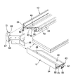
また、本発明に係るテーブルの奥行方向の中央部で、前記天板1,1を連結する位置に設けた前記中間脚3は、図5及び図13に示すように、奥行方向の前後両側に一対の支脚20,20を間隔を隔てて配置し、両支脚20,20の上端間に上向き開放した断面コ字形の支持杆21を渡設するとともに、下部間に連結杆22を連結し、更にそれぞれの支脚20の下端には左右方向へ向いた接地杆23を逆T字状に設け、該接地杆23の両端部にはアジャスター24,24を設けた構造である。前記支脚20は、断面コ字形の杆体25,25を左右に配し、前記支持杆21は両杆体25,25の上端に挟むように固定し、両杆体25,25を囲むように側板26が設けられている。尚、前記接地杆23を省略して前記両支脚20,20の下端に直接又は間接的にアジャスター24,24を設けることもある。 In addition, the intermediate leg 3 provided at the position where the top plates 1 and 1 are connected at the center in the depth direction of the table according to the present invention is arranged on both the front and rear sides in the depth direction as shown in FIGS. A pair of support legs 20 and 20 are arranged with a space therebetween, a U-shaped support rod 21 opened upward between the upper ends of both support legs 20 and 20 is provided, and a connection rod 22 is connected between the lower portions. A grounding rod 23 facing in the left-right direction is provided in an inverted T shape at the lower end of each support leg 20, and adjusters 24, 24 are provided at both ends of the grounding rod 23. The support legs 20 are provided with U-shaped cross-sections 25 and 25 on the left and right sides, the support bar 21 is fixed so as to be sandwiched between the upper ends of both the cases 25 and 25, and a side plate 26 surrounds both the cases 25 and 25. Is provided. The grounding rod 23 may be omitted, and adjusters 24, 24 may be provided directly or indirectly at the lower ends of the both support legs 20, 20.

そして、図6及び図7に示すような前記中間アーム8の中央部を、前記中間脚3の支持杆21の凹溝内に嵌合し、下方からネジ止めしている。前記中間アーム8は、角パイプで形成され、両端部に前記中間ブラケット10,10を取付け、中間部には前記取付片11,…の他に前記中間脚3の近傍位置に偏平な連結片27,27を設けている。また、前記中間脚3の両支脚20,20の上端左右両側には、前記ファンクションビーム9の端部を外嵌してネジ止め連結するための嵌合部28,28を突設している。   And the center part of the said intermediate | middle arm 8 as shown in FIG.6 and FIG.7 is fitted in the ditch | groove of the support rod 21 of the said intermediate | middle leg 3, and is screwed from the downward direction. The intermediate arm 8 is formed of a square pipe, and the intermediate brackets 10 and 10 are attached to both ends, and the connecting piece 27 is flat at a position near the intermediate leg 3 in addition to the attachment pieces 11,. 27 are provided. Further, on the left and right sides of the upper ends of both support legs 20 of the intermediate leg 3, fitting parts 28 and 28 are provided so as to externally fit the ends of the function beam 9 and connect them with screws.

前記縦ダクト4は、前記中間脚3を用いて構成されている。前記縦ダクト4は、図5に示すように、両支脚20,20の間に、上段コード受け29を前記支持杆21に吊止部材30を用いて吊り下げ状に設けるとともに、下段コード受け31を高さ調節可能に設け、更に前記中間脚3の両支脚20,20と上段コード受け29及び下段コード受け31を取り囲むように一対のダクトカバー32,32を対向配置し、該ダクトカバー32,32の両端縁部を両支脚20,20の外側側面に係着手段にて着脱可能且つ取付位置を側方へ変更可能に設けて構成されている。尚、前記縦ダクト4に対応する天板1にはコード引出し口を設けても良い。   The vertical duct 4 is configured using the intermediate leg 3. As shown in FIG. 5, the vertical duct 4 is provided with an upper cord receiver 29 suspended between the support legs 20, 20 using a suspension member 30 on the support rod 21, and a lower cord receiver 31. And a pair of duct covers 32, 32 are arranged opposite to each other so as to surround both the support legs 20, 20 of the intermediate leg 3 and the upper cord receiver 29 and the lower cord receiver 31, and the duct covers 32, Both end edges of 32 are provided on the outer side surfaces of both support legs 20 and 20 by attachment means so that the attachment position can be changed to the side. The top plate 1 corresponding to the vertical duct 4 may be provided with a cord outlet.

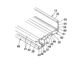
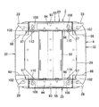
前記ファンクションエッジ12は、図3及び図7に示すように、前記天板1の側端面から下面縁部にかけて覆う形状になっており、複数の機能を備えている。先ず、前記ファンクションエッジ12は、前述の文字通り天板1のエッジ機能、天板1の補強機能、前記接続ユニット16等を取付けるオプション取付機能を備えている。前記ファンクションエッジ12は、アルミ押出し型材で作成されており、前記天板1の下面に接合する基板33の前端から立ち上がり前記天板1の側端面を覆う側面板34を有し、該側面板34の上縁から内方へ前記天板1の上面縁部を僅かに覆うことが可能な幅の狭い保護片35を延設し、エッジ機能を構成している。そして、前記ファンクションエッジ12の基板33を前記天板1の下面に取付け、前記側面板34で天板1の側端面を覆い、前記保護片35を天板1の上面端縁に係合した状態で配置する。このように、前記天板1の側端部が完全にファンクションエッジ12で覆われるので、該天板1の端部は切りっ放しで良く、特別な加工は不要となる。そのため、天板1は厚みさえ合わせれば、層構造は任意にでき、図示したように、木製のベース部1Aの上にガラス板1Bを接合した複合板にも対応できる。   As shown in FIGS. 3 and 7, the function edge 12 has a shape that covers from the side end surface of the top plate 1 to the lower surface edge, and has a plurality of functions. First, the function edge 12 is provided with the edge function of the top plate 1, the reinforcing function of the top plate 1, the optional attachment function for attaching the connection unit 16 and the like as described above. The function edge 12 is made of an aluminum extrusion mold, has a side plate 34 that rises from the front end of the substrate 33 to be joined to the lower surface of the top plate 1 and covers the side end surface of the top plate 1. A protective piece 35 having a narrow width that can slightly cover the upper surface edge of the top plate 1 is extended from the upper edge to the inside to constitute an edge function. Then, the substrate 33 of the function edge 12 is attached to the lower surface of the top plate 1, the side plate covers the side end surface of the top plate 1, and the protective piece 35 is engaged with the upper edge of the top plate 1. Place with. Thus, since the side edge part of the said top plate 1 is completely covered with the function edge 12, the edge part of this top plate 1 may be cut off, and a special process is unnecessary. Therefore, as long as the top plate 1 has the same thickness, the layer structure can be arbitrarily set. As shown in the figure, the top plate 1 can correspond to a composite plate in which a glass plate 1B is bonded onto a wooden base portion 1A.

更に、前記ファンクションエッジ12は、前記側面板34から下方へ延長し、それから後方へ前記基板33と平行に延びた下面板36を有し、該下面板36の後端に下方へ垂下板37を形成し、前記基板33の後端部から垂下した後面板38と前記垂下板37の下端を底面板39で連結して、中空の断面略L字形の本体部40を形成し、補強機能を構成している。   Furthermore, the function edge 12 has a lower surface plate 36 that extends downward from the side plate 34 and then extends rearward in parallel with the substrate 33, and a hanging plate 37 is formed downward at the rear end of the lower surface plate 36. The bottom plate 38 and the bottom plate 37 are connected to each other by a bottom plate 39 to form a main body portion 40 having a substantially L-shaped cross section. doing.

そして、前記ファンクションエッジ12は、前記基板33の後方延長部と前記底面板39の後方延長部の両端部から互いに接近する方向に延びた上下の係止板41,41と両係止板41,41の間に開口溝42を備えた内部に空間を有する係止レール部43を形成し、オプション取付機能を構成している。尚、前記係止板41,41の端部には、それぞれ外側、つまり天板1の端部側へ向けて延びた補強片44を形成し、前記係止板41とで断面略L字状の係止レール部43を構成している。勿論、前記係止レール部43も補強機能の一部を構成する。更に、前記下面板36の前後中間位置に凹溝45を形成するとともに、該凹溝45の開口縁に対応する前記下面板36の部分を延長して突片46,46を形成し、第二のオプション取付機能を構成している。つまり、本実施形態では、前記ファンクションエッジ12は、前記天板1の下面に取付ける補強機能を備えた中空の本体部40を有するとともに、該本体部40の内側に後方へ向いた係止レール部43を有し、該係止レール部43を用いて他部材を取付けるオプション取付機能を備えているのである。更に、前記ファンクションエッジ12の本体部40の下面に、開口縁に突片46,46を有する凹溝45を形成して、第二のオプション取付機能としている。   The function edge 12 includes upper and lower locking plates 41, 41 and both locking plates 41, extending in a direction approaching from both ends of the rear extension of the substrate 33 and the rear extension of the bottom plate 39. A locking rail portion 43 having a space in the interior provided with the opening groove 42 between 41 is formed to constitute an option mounting function. Reinforcing pieces 44 extending toward the outside, that is, toward the end of the top plate 1, are formed at the end portions of the locking plates 41, 41, respectively, and the cross section is substantially L-shaped with the locking plate 41. The latching rail part 43 is comprised. Of course, the locking rail portion 43 also constitutes a part of the reinforcing function. Further, a concave groove 45 is formed at the front and rear intermediate positions of the lower surface plate 36, and a portion of the lower surface plate 36 corresponding to the opening edge of the concave groove 45 is extended to form projecting pieces 46, 46, The optional mounting function is configured. That is, in the present embodiment, the function edge 12 has a hollow main body portion 40 having a reinforcing function to be attached to the lower surface of the top plate 1, and a locking rail portion facing rearward inside the main body portion 40. 43, and an optional attachment function for attaching other members using the locking rail portion 43 is provided. Further, a concave groove 45 having projecting pieces 46, 46 on the opening edge is formed on the lower surface of the main body portion 40 of the function edge 12 as a second option mounting function.

更に詳しくは、前記ファンクションエッジ12を前記天板1の下面にネジ止めするには、前記凹溝45内に開口47を形成し、それに対応する基板33に取付孔48を形成し、前記開口47から挿入したネジ49を取付孔48に挿入して天板1の下面に埋設したオニメナット等に螺合する。ここで、前記開口47は、ネジ49の頭部49Aが通過するのに十分な大きさを有し、前記ネジ49を天板1の下面へ螺合した状態でも頭部49Aが凹溝45内に突出しないように寸法設定され、ネジ49の存在を目立たなくしているとともに、前記凹溝45を利用する場合に支障がないようにしている。尚、前記凹溝45は、本発明に係るテーブルを移動させる際に、指を掛ける場合にも利用できる。   More specifically, in order to screw the function edge 12 to the lower surface of the top plate 1, an opening 47 is formed in the concave groove 45, a mounting hole 48 is formed in the corresponding substrate 33, and the opening 47 is formed. Are inserted into the mounting holes 48 and screwed into an omelet nut or the like embedded in the lower surface of the top plate 1. Here, the opening 47 is large enough to allow the head 49A of the screw 49 to pass through, and the head 49A remains in the concave groove 45 even when the screw 49 is screwed to the lower surface of the top plate 1. The size of the screw 49 is set so as not to protrude, and the presence of the screw 49 is made inconspicuous, and there is no problem when the concave groove 45 is used. The concave groove 45 can also be used when a finger is put on the table according to the present invention.

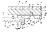
次に、前記天板1,1の接合部において、隣接する前記ファンクションエッジ12,12を前記連結金具13と連結板14を用いて直線状に連結する構造を図8及び図9に基づいて説明する。前記連結金具13は、厚さの厚い金属板からなる縦長断面四角形の芯金50の中央部に挿入杆51を平面視略T字形に側設し、前記芯金50の両側部には前後に開口した二つの螺孔52,52を形成するとともに、前記挿入杆51にも上下に開口した螺孔53,53を形成している。前記挿入杆51は上向きに開口した断面略コ字形の部材であり、内部にナットを溶接し、該ナットに連通する通孔を底面に形成して前記螺孔53,53とした。また、前記連結板14は、厚さの薄い金属板を折曲形成した部材であり、幅の広い垂直片54と幅が狭い水平片55とからなる。   Next, a structure in which the function edges 12 and 12 adjacent to each other at the joint portion of the top plates 1 and 1 are linearly connected using the connection fitting 13 and the connection plate 14 will be described with reference to FIGS. 8 and 9. To do. The connection fitting 13 is provided with an insertion rod 51 in the center of a vertically long rectangular cored bar 50 made of a thick metal plate in a T-shape in plan view, and on both sides of the cored bar 50 in the front-rear direction. The two screw holes 52 and 52 that are opened are formed, and the insertion hole 51 is also formed with screw holes 53 and 53 that are opened up and down. The insertion rod 51 is a member having an approximately U-shaped cross section that opens upward, and a nut is welded inside, and a through hole communicating with the nut is formed on the bottom surface to form the screw holes 53 and 53. The connecting plate 14 is a member formed by bending a thin metal plate, and includes a wide vertical piece 54 and a narrow horizontal piece 55.

前記ファンクションエッジ12の本体部40には、前記垂下板37、後面板38、底面板39及び基板33で囲まれた縦長の嵌合空間56が形成され、該嵌合空間56に前記連結金具13の芯金50の半分が嵌合される。この際、前記挿入杆51は、前記後面板38と、上側の係止板41及び補強片44の一部に形成した切欠部57を通して内側、つまり天板1の中央側へ向けて開口溝42から突出する。また、前記ファンクションエッジ12の側面板34と基板33の内側に沿って形成した嵌合部58に前記連結板14が嵌入される。前記ファンクションエッジ12の側面板34の近傍に嵌合部58を設け、直線状に隣接する両ファンクションエッジ12,12の嵌合部58に連結板14の両端部を嵌入することで、位置ずれを端縁に近いところで防止でき、より正確に連結できる。前記嵌合部58は、前記側面板34の内側上端に形成した下向き係合溝59と、前記基板33の手前側の外側縁部に設けた段落ち部60に形成した外向き係合溝61とで構成している。図4に示すように、前記ファンクションエッジ12を前記天板1に取付けた際に、前記天板1の側端面と側面板34及び基板33の段落ち部60との間に断面略L字形の空間が形成され、この空間内に前記連結板14を挿入して、垂直片54の上縁を前記下向き係合溝59に係合するとともに、水平片55の端部を前記外向き係合溝61に係合する。そして、前記ファンクションエッジ12の開口溝42内で、前記後面板38に形成した通孔62,62から挿入したネジ63,63を前記芯金50の螺孔52,52に螺合して強固に両ファンクションエッジ12,12を連結するとともに、前記連結板14を前記嵌合部58に嵌合することにより、側面板34と保護片35に位置ずれが無く連結することができる。そして、前記連結金具13の挿入杆51は、前記中間ブラケット10の先端面に開口した支持孔64に嵌入し、該中間ブラケット10の下方から挿入したネジ65,65を前記螺孔53,53に螺合して連結する。   In the body portion 40 of the function edge 12, a vertically long fitting space 56 surrounded by the hanging plate 37, the rear plate 38, the bottom plate 39 and the substrate 33 is formed, and the connecting fitting 13 is formed in the fitting space 56. Half of the core metal 50 is fitted. At this time, the insertion rod 51 is opened to the inner side, that is, toward the center side of the top plate 1 through the rear plate 38 and a notch 57 formed in a part of the upper locking plate 41 and the reinforcing piece 44. Protrude from. Further, the connecting plate 14 is fitted into a fitting portion 58 formed along the side plate 34 of the function edge 12 and the inside of the substrate 33. A fitting portion 58 is provided in the vicinity of the side plate 34 of the function edge 12 and both end portions of the connecting plate 14 are fitted into the fitting portions 58 of both the function edges 12 and 12 that are adjacent to each other in a straight line. It can be prevented near the edge and can be connected more accurately. The fitting portion 58 includes a downward engagement groove 59 formed on the inner upper end of the side plate 34 and an outward engagement groove 61 formed in a stepped portion 60 provided on the outer edge of the front side of the substrate 33. It consists of and. As shown in FIG. 4, when the function edge 12 is attached to the top plate 1, the cross section is substantially L-shaped between the side end surface of the top plate 1 and the side plate 34 and the stepped portion 60 of the substrate 33. A space is formed, and the connecting plate 14 is inserted into the space, and the upper edge of the vertical piece 54 is engaged with the downward engaging groove 59 and the end of the horizontal piece 55 is connected to the outward engaging groove. 61 is engaged. Then, in the opening groove 42 of the function edge 12, screws 63, 63 inserted from through holes 62, 62 formed in the rear plate 38 are screwed into the screw holes 52, 52 of the metal core 50 to be firmly attached. By connecting both the function edges 12 and 12 and fitting the connecting plate 14 to the fitting portion 58, the side plate 34 and the protective piece 35 can be connected without any positional deviation. Then, the insertion rod 51 of the connection fitting 13 is fitted into a support hole 64 opened at the front end surface of the intermediate bracket 10, and screws 65, 65 inserted from below the intermediate bracket 10 are inserted into the screw holes 53, 53. Screw together to connect.

また、テーブルのコーナー部においては、図10〜図12に示すように、前記コーナーブラケット15の基部には、前記ファンクションエッジ12の嵌合空間56に嵌入する嵌合片66,66を両側に突設するとともに、コーナー部のR面を形成するコーナー端面板67に前記嵌合部58に係合する断面略L字形の係合片68,68を両側に突設している。前記ファンクションエッジ12を天板1のコーナー部に取付けるには、前記係止レール部43の端部の開口溝42を前記脚ブラケット6の鍔部18に係合させて仮支持しながら、他端側を前記連結金具13と連結板14を用いて他のファンクションエッジ12に連結し、そして側端に位置するファンクションエッジ12の両端部に前記コーナーブラケット15,15を前述のように嵌合した状態で、該ファンクションエッジ12の開口溝42を両側の脚ブラケット6,6の鍔部18,18に係合すると同時に、両コーナーブラケット15,15の嵌合片66と係合片68を前後縁に設けた前記ファンクションエッジ12,12の端部に嵌合し、それから前述のように、ネジ49,…で天板1の下面に螺合する。   Further, at the corner portion of the table, as shown in FIGS. 10 to 12, the base bracket of the corner bracket 15 has fitting pieces 66, 66 that fit into the fitting space 56 of the function edge 12 projecting on both sides. In addition, engaging pieces 68, 68 having a substantially L-shaped cross section that engage with the fitting portion 58 are provided on both sides of a corner end face plate 67 that forms an R surface of the corner portion. In order to attach the function edge 12 to the corner portion of the top plate 1, the opening groove 42 at the end portion of the locking rail portion 43 is engaged with the flange portion 18 of the leg bracket 6 and temporarily supported while the other end. The side is connected to the other function edge 12 using the connection fitting 13 and the connection plate 14, and the corner brackets 15 and 15 are fitted to the both ends of the function edge 12 located at the side end as described above. Then, the opening groove 42 of the function edge 12 is engaged with the flanges 18 and 18 of the leg brackets 6 and 6 on both sides, and at the same time, the fitting pieces 66 and the engaging pieces 68 of the corner brackets 15 and 15 are used as front and rear edges. It fits into the end of the provided function edges 12, 12, and then is screwed onto the lower surface of the top plate 1 with screws 49,.

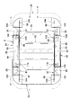
次に、図5、図13〜図17に基づいて、前記縦ダクト4によるアクセスフロアAからのケーブルCの配線例を説明する。前記縦ダクト4は、中間脚3の両支脚20,20の側板26,26の外面に、平面視略コ字形の1対のダクトカバー32,32の端縁部を係着手段により着脱可能且つ水平方向で取付位置を側方へ変更可能に係着できるようになっている。前記両支脚20,20の側板26,26及び1対のダクトカバー32,32で縦方向に連続したダクト空間が形成される。前記係着手段として、前記ダクトカバー32の両端縁部69,69の内側と前記両支脚20,20の側板26,26の一方にマグネット70,…を設け、他方面をスチール板等の吸着面71とし、前記マグネット70,…を吸着面71に吸着することによって前記ダクトカバー32を保持している。本実施形態では、ダクトカバー32の両端縁部69,69にマグネット70,…を設けている。そして、前記吸着面71に対する前記マグネット70,…による吸着位置を変えることにより、左右方向、つまり前記テーブルの長手方向にダクトカバー32の取付位置を変えることができる。ここで、前記ダクトカバー32の位置調節量を大きくするためには、前記中間脚3の両支脚20,20の側板26,26の横幅を広くすれば良い。尚、本実施形態では、係着手段としてマグネットとスチール板等の吸着面としたが、面ファスナーを用いることや、係合爪と係合孔、係止孔とフックを用いても良い。これらは、前記ダクトカバー32を少なくとも2段階に付け替えることができるように、前記両支脚20,20の側板26,26に左右方向に複数設ける。   Next, a wiring example of the cable C from the access floor A by the vertical duct 4 will be described based on FIGS. 5 and 13 to 17. The vertical duct 4 can be attached to and detached from the outer surfaces of the side plates 26 and 26 of the both supporting legs 20 and 20 of the intermediate leg 3 by engaging means with a pair of duct covers 32 and 32 having a substantially U-shape in plan view. It can be attached so that the mounting position can be changed laterally in the horizontal direction. The side plates 26 and 26 of the both support legs 20 and 20 and the pair of duct covers 32 and 32 form a duct space that is continuous in the vertical direction. As the engaging means, magnets 70,... Are provided on the inner side of both end edges 69, 69 of the duct cover 32 and one of the side plates 26, 26 of the support legs 20, 20, and the other surface is an adsorption surface such as a steel plate. The duct cover 32 is held by attracting the magnets 70 to the attracting surface 71. In the present embodiment, magnets 70 are provided at both end edges 69 of the duct cover 32. And the attachment position of the duct cover 32 can be changed to the left-right direction, ie, the longitudinal direction of the said table, by changing the adsorption | suction position by the said magnets 70 ... with respect to the said adsorption | suction surface 71. FIG. Here, in order to increase the position adjustment amount of the duct cover 32, the lateral widths of the side plates 26, 26 of both the supporting legs 20, 20 of the intermediate leg 3 may be increased. In the present embodiment, the attracting means is an attracting surface such as a magnet and a steel plate, but a hook-and-loop fastener, an engaging claw and an engaging hole, an engaging hole and a hook may be used. A plurality of these are provided in the left-right direction on the side plates 26, 26 of the both support legs 20, 20 so that the duct cover 32 can be replaced in at least two stages.

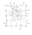
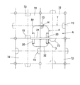
図14は、両ダクトカバー32,32を最も接近させて係着した状態を示し、図15は一方のダクトカバー32を左右方向に変化させてダクト空間を拡張させて係着した状態を示している。図15〜図17に示すように、前記アクセスフロアAは、1辺が50cmの正方形の床材72を隙間無く敷き詰め、両側縁の中央部にケーブルCの引出口73,73を設けている。前記床材72は、隣接する他の床材72同士は90度回転させた状態に交互に配列させ、どの位置でも4辺に接近して引出口73が位置するようにしている。そして、前記アクセスフロアAの上には1辺が50cmの正方形のタイルカーペットTを中心が床材72の頂角に位置するように半分ずらせて敷き詰めている。つまり、前記床材72の引出口73は、タイルカーペットTの側縁に位置するので、該タイルカーペットTの側縁を若干捲れば、前記引出口73の穴HからケーブルCを引き出すことができる。   FIG. 14 shows a state in which both duct covers 32, 32 are engaged most closely, and FIG. 15 shows a state in which one duct cover 32 is changed in the left-right direction so that the duct space is expanded and engaged. Yes. As shown in FIGS. 15 to 17, the access floor A is provided with a floor material 72 having a side of 50 cm without gaps, and cable outlets 73 and 73 are provided at the center of both side edges. The floor material 72 is alternately arranged in a state in which the other adjacent floor materials 72 are rotated by 90 degrees so that the outlet 73 is located close to the four sides at any position. A square tile carpet T having a side of 50 cm is placed on the access floor A so as to be shifted by half so that the center is located at the apex angle of the flooring 72. That is, since the outlet 73 of the floor material 72 is located at the side edge of the tile carpet T, the cable C can be pulled out from the hole H of the outlet 73 if the side edge of the tile carpet T is slightly turned. .

本実施形態では、前記縦ダクト4の通常状態における外形寸法は315mm角の正方形としている。但し、角部には丸みを設けている。通常、本発明に係るテーブルを所望位置に設置したとき、図16に示すように、大抵の場合には通常状態における前記縦ダクト4の内部に何れかの引出口73が位置するので、該当する引出口73の穴HからケーブルCを引き出し、タイルカーペットTの隙間から両ダクトカバー32,32間のダクト空間を通して天板1に配線することができる。特に、前記縦ダクト4は一つのテーブルに複数設けた場合には、その確率はさらに高まる。しかし、不幸にも、全ての縦ダクト4の内部に一つも引出口73が位置しない場合もある。図15に示すように、前記ダクトカバー32を側方へずらして係着することにより、ダクト空間の内部に引出口73を取り込むことができる。図17に示すように、縦ダクト4の中心が床材72の頂角に位置する最悪条件の場合にも、前記ダクトカバー32を側方へずらしてダクト空間の内部に引出口73の穴Hを取り込むことができるようにするには、前記ダクトカバー32の取付位置を92.5mmだけ変えられるようにすれば良い。そのためには、前記中間脚3の支脚20の側板26の幅を最低185mmは必要であり、重ねしろを考慮すれば実際には22〜23cm程度あれば十分である。この程度であれば、両ダクトカバー32,32を再接近させた通常状態でも、干渉することなく内部に側板26を位置させることができる。   In the present embodiment, the outer dimension of the vertical duct 4 in a normal state is a 315 mm square. However, the corner is rounded. Normally, when the table according to the present invention is installed at a desired position, as shown in FIG. 16, in most cases, any outlet 73 is located inside the vertical duct 4 in the normal state. The cable C can be pulled out from the hole H of the outlet 73 and wired to the top board 1 through the duct space between the duct covers 32 and 32 through the gap between the tile carpets T. In particular, when a plurality of the vertical ducts 4 are provided on one table, the probability is further increased. However, unfortunately, there is a case where none of the outlets 73 is located inside all the vertical ducts 4. As shown in FIG. 15, the outlet 73 can be taken into the duct space by shifting the duct cover 32 to the side and engaging it. As shown in FIG. 17, even in the worst condition where the center of the vertical duct 4 is located at the apex angle of the flooring 72, the duct cover 32 is shifted to the side and the hole H of the outlet 73 is formed inside the duct space. In order to be able to take in, the attachment position of the duct cover 32 may be changed by 92.5 mm. For this purpose, the width of the side plate 26 of the support leg 20 of the intermediate leg 3 needs to be at least 185 mm. In consideration of the overlap, it is actually sufficient to be about 22 to 23 cm. If it is this extent, the side plate 26 can be located inside without interfering even in the normal state in which both duct covers 32, 32 are reapproached.

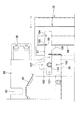
前記縦ダクト4を用いて天板1下面まで配線したケーブルCは、テーブルの下面縁部に設けた前記接続ユニット16まで配線され、天板1上で使用する電子機器に対する電源コードやLANケーブルを手元で接続することができる。前記接続ユニット16は、図18〜図20に示すように、接続ボックス74と、前記ファンクションエッジ12の係止レール部43に取付けるための取付金具75とからなり、前記接続ボックス74には、電源コードC2のコンセントを接続する差込口76が前面に複数形成されている。前記差込口76は、LANケーブルの場合にはRJ−45等のコネクターを設ける。前記取付金具75は、金属板をクランク状に屈曲した取付部材77の下部を前記接続ボックス74の背面に取付け、上部に設けた締結具78を用いて前記ファンクションエッジ12の係止レール部43に取付ける。   The cable C wired to the lower surface of the top plate 1 using the vertical duct 4 is wired to the connection unit 16 provided on the lower surface edge of the table, and a power cord or a LAN cable for an electronic device used on the top plate 1 is connected. Can be connected at hand. As shown in FIGS. 18 to 20, the connection unit 16 includes a connection box 74 and a mounting bracket 75 for mounting to the locking rail portion 43 of the function edge 12. A plurality of insertion ports 76 for connecting the outlet of the cord C2 are formed on the front surface. The insertion port 76 is provided with a connector such as RJ-45 in the case of a LAN cable. The mounting bracket 75 has a lower portion of a mounting member 77 formed by bending a metal plate in a crank shape attached to the back surface of the connection box 74, and a fastener 78 provided on the upper portion, to the locking rail portion 43 of the function edge 12. Install.

前記取付金具75の取付部材77は、前記接続ボックス74の背面にネジ79,79を用いて取付ける取付板80と、該取付板80から手前側に直角に折曲した屈曲板81と、該屈曲板81の手前端から垂直に立ち上がった支持板82とからなり、前記締結具78は前記支持板82の通孔83,83に後側から挿通した締結ネジ84,84の端部に螺合したコマ片85,85とからなっている。前記コマ片85は、短尺寸法が前記係止レール部43の開口溝42の開口幅よりも小さく、長尺寸法が前記係止レール部43の内部空間の上下寸法より大きく、両端を斜めにカットして前記基板33と底面板39に当接する当接部86,86を形成した正面視で平行四辺形の形状である。   The mounting member 77 of the mounting bracket 75 includes a mounting plate 80 mounted on the back surface of the connection box 74 using screws 79, 79, a bent plate 81 bent at a right angle from the mounting plate 80 to the front side, and the bent The fastener 78 is screwed into the end portions of the fastening screws 84 and 84 inserted from the rear side into the through holes 83 and 83 of the support plate 82. The support plate 82 rises vertically from the front end of the plate 81. It consists of frame pieces 85 and 85. The top piece 85 has a short dimension smaller than the opening width of the opening groove 42 of the locking rail portion 43, a long dimension larger than the vertical dimension of the internal space of the locking rail portion 43, and both ends obliquely. The shape is a parallelogram in a front view in which the abutting portions 86, 86 are formed by cutting and abutting against the substrate 33 and the bottom plate 39.

そして、前記接続ユニット16は、図18及び図19に示すように、前記取付部材77の取付板80を前記接続ボックス74の背面に接合するとともに、前記屈曲板81を該接続ボックス74の上面に接合した状態で、取付板80をネジ79,79で取付け、前記取付部材77の支持板82に前記締結具78,78を装着し、ユニット化する。それから、図19に示すように、前記締結具78,78のコマ片85,85を水平に直列させた状態で、前記ファンクションエッジ12の係止レール部43の開口溝42に後方から挿入し、前記接続ボックス74の上面を底面板39に当接した状態で前記締結ネジ84を締付けると、最初は前記コマ片85は供回りするが、当接部86,86が前記基板33と底面板39に当接してからは回転が規制され徐々に引き付けられ、遂には前記係止板41,41に形成した補強片44,44に当接し、該コマ片85と前記支持板82とで補強片44,44を締付けて取付ける。   As shown in FIGS. 18 and 19, the connection unit 16 joins the mounting plate 80 of the mounting member 77 to the back surface of the connection box 74 and the bent plate 81 on the upper surface of the connection box 74. In the joined state, the attachment plate 80 is attached with screws 79, 79, and the fasteners 78, 78 are attached to the support plate 82 of the attachment member 77 to form a unit. Then, as shown in FIG. 19, the piece pieces 85, 85 of the fasteners 78, 78 are horizontally inserted in series into the opening groove 42 of the locking rail portion 43 of the function edge 12 from the rear, When the fastening screw 84 is tightened in a state where the upper surface of the connection box 74 is in contact with the bottom plate 39, the top piece 85 is initially rotated, but the contact portions 86, 86 are connected to the substrate 33 and the bottom plate 39. , The rotation is regulated and gradually attracted, and finally comes into contact with the reinforcing pieces 44 and 44 formed on the locking plates 41 and 41, and the reinforcing piece 44 is formed by the piece 85 and the support plate 82. , 44 are attached.

前記接続ユニット16を前記ファンクションエッジ12に取付けた状態では、前記接続ボックス74の前面は、前記ファンクションエッジ12の垂下板37と略面一となる。つまり、前記接続ボックス74の差込口76の位置は、前記天板1の端縁から後退した位置になる。それにより、前記接続ボックス74の差込口76に天板1の上面に置いた電子機器からのケーブルC2のプラグ87を接続した際に、ケーブルC2が天板1の端縁から大きく突出することがなくなる。また、前記締結具78,78を緩めれば、前記接続ユニット16は前記ファンクションエッジ12の係止レール部43に沿った任意の位置に移動させることができる。   In a state where the connection unit 16 is attached to the function edge 12, the front surface of the connection box 74 is substantially flush with the hanging plate 37 of the function edge 12. That is, the position of the insertion port 76 of the connection box 74 is a position retracted from the edge of the top plate 1. Thereby, when the plug 87 of the cable C2 from the electronic device placed on the top surface of the top plate 1 is connected to the insertion port 76 of the connection box 74, the cable C2 greatly protrudes from the edge of the top plate 1. Disappears. Further, if the fasteners 78 are loosened, the connection unit 16 can be moved to an arbitrary position along the locking rail portion 43 of the function edge 12.

図21には前記ファンクションエッジ12を他の実施形態を示している。本実施形態のファンクションエッジ12は、前記天板1上にこぼした水等の液体が前記保護片35と天板1の隙間から浸入し、基板33の上に溜まることを防止できる構造とした。この場合、前記天板1の下面縁部を斜めにカットして面取り部88を形成している。そして、前記ファンクションエッジ12は、前記基板33の手前側部分を前記面取り部88に対応した傾斜板89とし、該傾斜板89の中間部に全長にわたり排水溝90を形成し、該排水溝90と下面板36との適所に排水孔91,91を形成している。その他の構造で前述のものと異なるところは、前記下面板36の手前端部分を下方へ膨出させ(膨出部36A)、その後方に前記垂下板37に至るまでを凹溝45とし、前記本体部40の中空部の手前端(外側縁部)に上下に対向させて係合溝59,61を形成し、嵌合部58としたところにある。尚、前記凹溝45の開口縁には突片46を設けない。この場合、前記下面板36の手前側膨出部36Aは前記凹溝45に指を掛けるのに適したものとなり、また内部は樋状になるので排水溝としての機能を有し、こぼれた液体は最終的にこの膨出部36Aに形成された排水孔91から外部に排水される。また、前記ファンクションエッジ12,12同士を連結する場合、係止レール部43に沿って形成された嵌合空間56には前記同様な連結金具13の芯金50を挿入するが、前記本体部40の内部に設けた前記嵌合部58には単純な厚板状の連結板14を上下の係合溝59,61に係合させて挿入する。その他の構造は前記同様であるので、同一符号を付してその説明は省略する。   FIG. 21 shows another embodiment of the function edge 12. The function edge 12 of the present embodiment has a structure that can prevent liquid such as water spilled on the top plate 1 from entering the gap between the protective piece 35 and the top plate 1 and accumulating on the substrate 33. In this case, the chamfered portion 88 is formed by obliquely cutting the lower surface edge of the top plate 1. The function edge 12 has a front side portion of the substrate 33 as an inclined plate 89 corresponding to the chamfered portion 88, and a drainage groove 90 is formed over the entire length of the intermediate portion of the inclined plate 89. Drain holes 91 and 91 are formed at appropriate positions with the lower surface plate 36. The other structure is different from the above-described one in that the front end portion of the lower surface plate 36 is bulged downward (bulged portion 36A), and the concave groove 45 is formed behind it until the drooping plate 37 is reached. Engaging grooves 59 and 61 are formed on the front end (outer edge) of the hollow portion of the main body portion 40 so as to be opposed to each other in the vertical direction, thereby forming a fitting portion 58. Note that no protruding piece 46 is provided at the opening edge of the concave groove 45. In this case, the front side bulging portion 36A of the lower surface plate 36 is suitable for putting a finger on the concave groove 45, and the inside has a bowl shape so that it has a function as a drainage groove. Is finally drained to the outside through a drain hole 91 formed in the bulging portion 36A. Further, when the function edges 12 are connected to each other, the same metal core 50 of the connection fitting 13 is inserted into the fitting space 56 formed along the locking rail portion 43, but the main body portion 40. A simple thick plate-like connecting plate 14 is inserted into the fitting portion 58 provided inside the upper and lower engaging grooves 59 and 61. Since other structures are the same as those described above, the same reference numerals are given and description thereof is omitted.

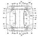
次に、図22〜図28に基づいて、本発明に係る縦ダクト4の他の実施形態を中間脚3とともに説明する。先ず、前記縦ダクト4の骨格となる中間脚3の構造を説明する。本実施形態の中間脚3は、両側に剛性の高い板状の支脚20,20を対面させて並行に配し、両支脚20,20間に、コード類を受ける受部材92、上段コード受け29及び下段コード受け31を連結することにより構造的に剛性を高め、前記各支脚20の下端にはアジャスター24,24を設けている。そして、前記支脚20,20の上端中央部に、前記中間アーム8の中央部を嵌合して固定するための凹部93,93を形成し、凹部93内には固定板94が設けられている。そして、前記同様のダクトカバー32,32を前記両支脚20,20の外側面95に被さるように支持し、内部にダクト空間を形成して縦ダクト4を構成している。   Next, another embodiment of the vertical duct 4 according to the present invention will be described together with the intermediate leg 3 based on FIGS. First, the structure of the intermediate leg 3 serving as the skeleton of the vertical duct 4 will be described. The intermediate leg 3 of the present embodiment is arranged in parallel with the plate-shaped support legs 20, 20 having high rigidity facing each other on both sides, and a receiving member 92 that receives cords between the support legs 20, 20 and an upper-stage code receiver 29. The lower cord receiver 31 is connected to increase the structural rigidity, and adjusters 24, 24 are provided at the lower ends of the respective support legs 20. And the recessed part 93,93 for fitting and fixing the center part of the said intermediate | middle arm 8 is formed in the upper-end center part of the said support legs 20,20, The fixing plate 94 is provided in the recessed part 93. FIG. . The duct covers 32, 32 similar to those described above are supported so as to cover the outer side surfaces 95 of the both support legs 20, 20, and a duct space is formed inside to constitute the vertical duct 4.

前記ダクトカバー32は、前記支脚20の内側面96に取付けた係止金具97を用いて、内外に多段階位置に係止できるようになっている。尚、前記ダクトカバー32の両コーナー部の内側には、図22〜図24に示すように、アングル状の補強部材98.98が固着されており、該補強部材98の前記支脚20に対面する面の上下部には、前記係止金具97に係止する係止孔99と係止凹部100を形成している。本発明における係着手段は、前記係止金具97及び係止孔99と係止凹部100で構成している。前記係止凹部100は、補強部材98の下端を切り欠いて設けた。前記係止孔99及び係止凹部100の上部は同じ形状となっており、位置決め精度を高めるために、前記係止金具97の板厚に相当する狭い係合溝101となっている。   The duct cover 32 can be locked at multiple stages inside and outside by using a locking metal fitting 97 attached to the inner side surface 96 of the support leg 20. As shown in FIGS. 22 to 24, angle-shaped reinforcing members 98.98 are fixed to the inside of both corner portions of the duct cover 32, and face the support legs 20 of the reinforcing member 98. A locking hole 99 and a locking recess 100 for locking to the locking metal fitting 97 are formed in the upper and lower portions of the surface. The engaging means in the present invention is constituted by the locking metal piece 97, the locking hole 99 and the locking recess 100. The locking recess 100 is provided by cutting out the lower end of the reinforcing member 98. The upper portions of the locking hole 99 and the locking recess 100 have the same shape, and are narrow engagement grooves 101 corresponding to the plate thickness of the locking fitting 97 in order to increase positioning accuracy.

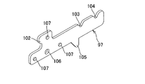
前記係止金具97は、図25に示すように、長尺の板部材であり、長手方向に沿った一側縁の一端部に端部側へ向けてフック状の第1係止部102を形成し、他端部には間隔を隔てて中央寄りから凹部となった第2係止部103、第3係止部104が形成されている。また、前記係止金具97の長手方向に沿った他側縁、即ち前記第1係止部102を設けた側とは反対側の中央部に三角形状の当止片105を突設するとともに、前記第1係止部102を形成した部分の略中央部に取付孔106を形成し、該取付孔106の周囲に該取付孔106の中心から等距離位置に3個のダボ107,…を、係止金具97の長手方向に2個、前記第1係止部102を形成したフック部の側面に1個突設している。一方、前記支脚20の内側面96の上下部の両側縁部に、つまり4箇所に前記係止金具97をネジ止めするための螺孔108,…を形成するとともに、該螺孔108の周囲に前記ダボ107,…のいずれか嵌合する孔109,…を三箇所に設けている。尚、前記係止金具97は、左右で半対称形であるから2種を用意する。   As shown in FIG. 25, the locking fitting 97 is a long plate member, and a hook-shaped first locking portion 102 is provided at one end of one side edge along the longitudinal direction toward the end. A second locking portion 103 and a third locking portion 104 are formed at the other end portion, with a gap from the center toward the other end portion. In addition, a triangular stopper piece 105 protrudes from the other side edge along the longitudinal direction of the locking metal fitting 97, that is, a central portion opposite to the side where the first locking portion 102 is provided, A mounting hole 106 is formed at a substantially central portion of the portion where the first locking portion 102 is formed, and three dowels 107,... Are equidistant from the center of the mounting hole 106 around the mounting hole 106. Two locking metal fittings 97 are provided in the longitudinal direction, and one is provided on the side surface of the hook portion where the first locking portion 102 is formed. On the other hand, screw holes 108 are formed in the upper and lower side edges of the inner side surface 96 of the support leg 20, that is, at four positions, and screw holes 108,... Are screwed around the screw holes 108. The holes 109,... For fitting any one of the dowels 107,. Note that two types of the locking metal fittings 97 are prepared because they are semi-symmetrical on the left and right.

先ず、図22及び図26に示すように、前記係止金具97を垂直にして、前記第1係止部102が前記支脚20の端部から突出する姿勢で、ネジ110を前記取付孔106に挿通して、支脚20の螺孔108に螺合する。このとき、係止金具97の長手方向の二つのダボ107,107が、内側面96の上下の孔109,109に嵌合して正確な角度に保持される。そして、各係止金具97の第1係止部102に前記ダクトカバー32の係止孔99及び係止凹部100を係止する。このとき、前記補強部材98は支脚20の端面に当接し、最も接近した位置にダクトカバー32が支持され、内部のダクト空間は最も狭くなる。   First, as shown in FIGS. 22 and 26, the screw 110 is inserted into the mounting hole 106 in a posture in which the locking metal fitting 97 is vertical and the first locking portion 102 protrudes from the end of the support leg 20. It is inserted and screwed into the screw hole 108 of the support leg 20. At this time, the two dowels 107 and 107 in the longitudinal direction of the locking metal fitting 97 are fitted into the upper and lower holes 109 and 109 of the inner surface 96 and are held at an accurate angle. Then, the locking hole 99 and the locking recess 100 of the duct cover 32 are locked to the first locking portion 102 of each locking metal fitting 97. At this time, the reinforcing member 98 abuts against the end face of the support leg 20, the duct cover 32 is supported at the closest position, and the internal duct space becomes the narrowest.

次に、前記ダクトカバー32を外側に変位させて支持する例を図27及び図28に基づいて説明する。それには、前記係止金具97を水平にして、前記第2係止部103、第3係止部104を上に向けた状態で、前記ネジ110を前記取付孔106に挿通して、支脚20の螺孔108に螺合する。このとき、前記係止金具97の端部と第1係止部102のフック部に設けたダボ107,107が、内側面96の内側と上方の孔109,109に嵌合して正確な角度に保持される。そして、水平状態の前記係止金具97の端部から前記ダクトカバー32の係止孔99に挿入し、前記係止凹部100を前記第2係止部103又は第3係止部104に係止する。前記第2係止部103に係止した場合には、前記当止片105が前記補強部材98に当止してそれ以上の内方変位を規制する。前記第2係止部103に係止した場合(実線)が、前記ダクトカバー32を二番目に外側に変位させた態様であり、また第3係止部104に係止した場合(想像線)が、前記ダクトカバー32を三番目、つまり最も外側に変位させた態様である。   Next, an example in which the duct cover 32 is displaced outwardly and supported will be described with reference to FIGS. For this purpose, the screw 110 is inserted into the mounting hole 106 with the locking metal fitting 97 horizontal and the second locking portion 103 and the third locking portion 104 facing upward, and the support leg 20 The screw hole 108 is screwed. At this time, the dowels 107 and 107 provided on the end portion of the locking metal fitting 97 and the hook portion of the first locking portion 102 are fitted into the holes 109 and 109 on the inner side and the upper side of the inner side surface 96, so that an accurate angle is obtained. Retained. And it inserts in the locking hole 99 of the said duct cover 32 from the edge part of the said locking metal fitting 97 of a horizontal state, and locks the said locking recessed part 100 in the said 2nd locking part 103 or the 3rd locking part 104. To do. When locked to the second locking portion 103, the locking piece 105 contacts the reinforcing member 98 to restrict further inward displacement. When the second locking portion 103 is locked (solid line), the duct cover 32 is displaced second outward, and when it is locked to the third locking portion 104 (imaginary line). However, the duct cover 32 is displaced third, that is, on the outermost side.

最後に、図29〜図33に基づいて、本発明に係る縦ダクト4の更に他の実施形態を説明する。本実施形態は、図22〜図28に示した実施形態の変形例であり、基本構成は前述の実施形態と同様であるので、同一構成には同一符号を付して、その説明は省略する。本実施形態も前記ダクトカバー32は、前記支脚20の内側面96に取付けた係止金具111を用いて、内外に2段階位置に係止できるようになっている。また、前記ダクトカバー32の両コーナー部の内側に設けた補強部材98.98は、本実施形態では、直交した二つの側面98A,98Aのコーナー部に面取り部98Bを形成した形状であり、前記支脚20の端面に対面する一つの側面98Aの上下部には、前記係止金具111に係止する係止孔99と係止凹部100を形成している。本発明における係着手段は、前記係止金具111及び係止孔99と係止凹部100で構成している。前記係止孔99及び係止凹部100の上部は同じ形状となっており、位置決め精度を高めるために、前記係止金具111の板厚に相当する上端までテーパー状の係合溝101となっている。   Finally, still another embodiment of the vertical duct 4 according to the present invention will be described based on FIGS. 29 to 33. This embodiment is a modification of the embodiment shown in FIGS. 22 to 28, and the basic configuration is the same as that of the above-described embodiment. Therefore, the same components are denoted by the same reference numerals, and the description thereof is omitted. . Also in this embodiment, the duct cover 32 can be locked at the two-stage position inside and outside by using a locking fitting 111 attached to the inner side surface 96 of the support leg 20. Further, the reinforcing member 98.98 provided inside both corner portions of the duct cover 32 has a shape in which chamfered portions 98B are formed at the corner portions of two orthogonal side surfaces 98A and 98A in the present embodiment. A locking hole 99 and a locking recess 100 for locking to the locking metal fitting 111 are formed on the upper and lower portions of one side surface 98A facing the end surface of the support leg 20. The engaging means in the present invention is constituted by the locking metal fitting 111, the locking hole 99 and the locking recess 100. The upper portions of the locking hole 99 and the locking recess 100 have the same shape, and in order to increase the positioning accuracy, the engaging groove 101 is tapered to the upper end corresponding to the plate thickness of the locking fitting 111. Yes.

前記係止金具111は、図32に示すように、長尺の板部材であり、長手方向に沿った一側縁の一端部に端部側へ向けてフック状の第1係止部102を形成し、他端部には凹部となった第2係止部103が形成されている。本実施形態の第1係止部102と第2係止部103は、凹部の底部を深く切り込み、前記補強部材98の内外から挟持した状態で形成できる形状である。また、前記係止金具111の長手方向に沿った他側縁、即ち前記第1係止部102を設けた側とは反対側に三角形状の当止片105を突設するとともに、前記第1係止部102を形成した部分の略中央部に取付孔106を形成し、該取付孔106の周囲に該取付孔106の中心から等距離位置に3個のダボ107,…を、係止金具111の長手方向に2個、前記第1係止部102を形成したフック部の側面に1個突設している。一方、前記支脚20の内側面96の上下部の両側縁部に、つまり4箇所に前記係止金具111をネジ止めするための螺孔108,…を形成するとともに、該螺孔108の周囲に前記ダボ107,…のいずれか嵌合する孔109,…を三箇所に設けている。尚、前記係止金具111は、左右で半対称形であるから2種を用意する。   As shown in FIG. 32, the locking fitting 111 is a long plate member, and a hook-shaped first locking portion 102 is provided at one end of one side edge along the longitudinal direction toward the end. A second locking portion 103 formed as a recess is formed at the other end. The first locking portion 102 and the second locking portion 103 of the present embodiment have a shape that can be formed in a state where the bottom portion of the recess is deeply cut and sandwiched from inside and outside the reinforcing member 98. In addition, a triangular stopper piece 105 projects from the other edge along the longitudinal direction of the locking metal fitting 111, that is, the side opposite to the side where the first locking portion 102 is provided, and the first A mounting hole 106 is formed at a substantially central portion of the portion where the locking portion 102 is formed, and three dowels 107 are arranged around the mounting hole 106 at equal distances from the center of the mounting hole 106. Two projections are provided in the longitudinal direction of 111, and one projection is provided on the side surface of the hook portion on which the first locking portion 102 is formed. On the other hand, screw holes 108 are formed in the upper and lower side edges of the inner side surface 96 of the support leg 20, that is, at four locations, and screw holes 108,. The holes 109,... For fitting any one of the dowels 107,. Two types of the locking metal fittings 111 are prepared because they are semi-symmetrical on the left and right.

先ず、図29に示すように、前記係止金具111を垂直にして、前記第1係止部102が前記支脚20の端部から突出する姿勢で、ネジ110を前記取付孔106に挿通して、支脚20の螺孔108に螺合する。このとき、係止金具111の長手方向の二つのダボ107,107が、内側面96の上下の孔109,109に嵌合して正確な角度に保持される。そして、各係止金具111の第1係止部102に前記ダクトカバー32の係止孔99及び係止凹部100を係止する。このとき、前記補強部材98は係止金具111の側縁に当接し、最も接近した位置にダクトカバー32が支持され、内部のダクト空間は最も狭くなる。   First, as shown in FIG. 29, the screw 110 is inserted into the mounting hole 106 in a posture in which the locking metal fitting 111 is vertical and the first locking portion 102 protrudes from the end of the support leg 20. And screwed into the screw hole 108 of the support leg 20. At this time, the two dowels 107 and 107 in the longitudinal direction of the locking metal fitting 111 are fitted into the upper and lower holes 109 and 109 of the inner surface 96 and are held at an accurate angle. Then, the locking holes 99 and the locking recesses 100 of the duct cover 32 are locked to the first locking portions 102 of the locking metal fittings 111. At this time, the reinforcing member 98 abuts on the side edge of the locking fitting 111, the duct cover 32 is supported at the closest position, and the internal duct space becomes the narrowest.

次に、前記ダクトカバー32を外側に変位させて支持する例を図33に基づいて説明する。それには、前記係止金具111を水平にして、前記第2係止部103を上に向けた状態で、前記ネジ110を前記取付孔106に挿通して、支脚20の螺孔108に螺合する。このとき、前記係止金具111の端部と第1係止部102のフック部に設けたダボ107,107が、内側面96の内側と上方の孔109,109に嵌合して正確な角度に保持される。そして、水平状態の前記係止金具111の端部から前記ダクトカバー32の係止孔99に挿入し、前記係止凹部100を前記第2係止部103に係止する。前記ダクトカバー32が持ち上がって、第2係止部103から係止孔99が外れた場合には、前記当止片105が前記補強部材98に当止してそれ以上の内方変位を規制する。   Next, an example in which the duct cover 32 is displaced outward and supported will be described with reference to FIG. For this purpose, the screw 110 is inserted into the mounting hole 106 and screwed into the screw hole 108 of the support leg 20 with the locking metal fitting 111 horizontal and the second locking portion 103 facing upward. To do. At this time, the dowels 107 and 107 provided at the end of the locking metal fitting 111 and the hook portion of the first locking portion 102 are fitted into the holes 109 and 109 on the inner side and the upper side of the inner side surface 96 so that an accurate angle is obtained. Retained. And it inserts in the locking hole 99 of the said duct cover 32 from the edge part of the said locking metal fitting 111 of a horizontal state, and the said locking recessed part 100 is locked to the said 2nd locking part 103. FIG. When the duct cover 32 is lifted and the locking hole 99 is disengaged from the second locking portion 103, the locking piece 105 is locked against the reinforcing member 98 to restrict further inward displacement. .

1 天板、 1A ベース部、
1B ガラス板、 2 棒脚、
3 中間脚、 4 縦ダクト、
5 キャビネット、 6 脚ブラケット、
7 エンドアーム、 8 中間アーム、
9 ファンクションビーム、 10 中間ブラケット、
11 取付片、 12 ファンクションエッジ、
13 連結金具、 14 連結板、
15 コーナーブラケット、 16 接続ユニット、
17 嵌合部、 18 鍔部、
19 固定筒、 20 支脚、
21 支持杆、 22 連結杆、
23 接地杆、 24 アジャスター、
25 杆体、 26 側板、
27 連結片、 28 嵌合部、
29 上段コード受け、 30 受部材、
31 下段コード受け、 32 ダクトカバー、
33 基板、 34 側面板、
35 保護片、 36 下面板、
37 垂下板、 38 後面板、
39 底面板、 40 本体部、
41 係止板、 42 開口溝、
43 係止レール部、 44 補強片、
45 凹溝、 46 突片、
47 開口、 48 取付孔、
49 ネジ、 49A 頭部、
50 芯金、 51 挿入杆、
52 螺孔、 53 螺孔、
54 垂直片、 55 水平片、
56 嵌合空間、 57 切欠部、
58 嵌合部、 59 係合溝、
60 段落ち部、 61 係合溝、
62 通孔、 63 ネジ、
64 支持孔、 65 ネジ、
66 嵌合片、 67 コーナー端面板、
68 係合片、 69 端縁部、
70 マグネット、 71 吸着面、
72 床材、 73 引出口、
74 接続ボックス、 75 取付金具、
76 差込口、 77 取付部材、
78 締結具、 79 ネジ、
80 取付板、 81 屈曲板、
82 支持板、 83 通孔、
84 締結ネジ、 85 コマ片、
86 当接部、 87 プラグ、
88 面取り部、 89 傾斜板、
90 排水溝、 91 排水孔、
92 受部材、 93 凹部、
94 固定板、 95 外側面、
96 内側面、 97 係止金具、
98 補強部材、 99 係止孔、
100 係止凹部、 101 係合溝、
102 第1係止部、 103 第2係止部、
104 第3係止部、 105 当止片、
106 取付孔、 107 ダボ、
108 螺孔、 109 孔、
110 ネジ、 111 係止金具、
A アクセスフロア、
H 穴、
C,C1,C2 ケーブル、
T タイルカーペット。
1 Top plate, 1A Base part,
1B glass plate, 2 rod legs,
3 intermediate legs, 4 vertical ducts,
5 cabinets, 6 leg brackets,
7 End arm, 8 Middle arm,
9 Function beam, 10 Intermediate bracket,
11 Mounting piece, 12 Function edge,
13 connecting bracket, 14 connecting plate,
15 corner brackets, 16 connection units,
17 fitting part, 18 collar part,
19 fixed cylinders, 20 support legs,
21 support rods, 22 connecting rods,
23 Grounding rod, 24 Adjuster,
25 housing, 26 side plate,
27 connecting pieces, 28 fitting portions,
29 Upper cord receiver, 30 receiving member,
31 Lower cord holder, 32 Duct cover,
33 substrate, 34 side plate,
35 protective pieces, 36 bottom plate,
37 Hanging plate, 38 Rear plate,
39 bottom plate, 40 main body,
41 locking plate, 42 opening groove,
43 Locking rail part, 44 Reinforcing piece,
45 groove, 46 protrusion,
47 opening, 48 mounting hole,
49 screws, 49A head,
50 cored bar, 51 insertion rod,
52 screw holes, 53 screw holes,
54 vertical pieces, 55 horizontal pieces,
56 mating space, 57 notch,
58 fitting part, 59 engaging groove,
60 stepped part, 61 engaging groove,
62 through holes, 63 screws,
64 support holes, 65 screws,
66 fitting pieces, 67 corner end face plates,
68 engagement pieces, 69 end edges,
70 magnet, 71 adsorption surface,
72 flooring, 73 outlets,
74 connection box, 75 mounting bracket,
76 socket, 77 mounting member,
78 fasteners, 79 screws,
80 mounting plate, 81 bending plate,
82 support plate, 83 through-hole,
84 Fastening screws, 85 top pieces,
86 contact part, 87 plug,
88 chamfer, 89 inclined plate,
90 drainage groove, 91 drainage hole,
92 receiving member, 93 recess,
94 fixing plate, 95 outer surface,
96 inner surface, 97 locking bracket,
98 reinforcement members, 99 locking holes,
100 engaging recess, 101 engaging groove,
102 first locking portion, 103 second locking portion,
104 third locking part, 105 stop piece,
106 mounting holes, 107 dowels,
108 screw holes, 109 holes,
110 screws, 111 locking brackets,
A access floor,
H hole,
C, C1, C2 cable,
T tile carpet.

Claims (6)

複数の天板を横方向に連設し、該天板を支持する中間脚に配線用の縦ダクトを設けてなるテーブルにおいて、前記中間脚は、間隔を隔てて配置した一対の支脚を備え、前記縦ダクトは、前記中間脚の両支脚を取り囲むように、平面視略コ字形の一対のダクトカバーを対向配置し、前記両支脚の外側側面に、前記ダクトカバーの両端縁部を係着手段にて着脱可能且つ取付位置を側方へ変更可能に係着し、両支脚及び1対のダクトカバーで縦方向に連続したダクト空間が形成されたことを特徴とするテーブルの配線ダクト装置。 In a table in which a plurality of top plates are arranged in a horizontal direction and a vertical duct for wiring is provided on an intermediate leg that supports the top plate, the intermediate legs include a pair of support legs arranged at intervals. The vertical duct is provided with a pair of substantially U-shaped duct covers in plan view so as to surround both support legs of the intermediate leg, and both end edges of the duct cover are engaged with the outer side surfaces of the both support legs. A wiring duct device for a table, characterized in that a duct space that is detachably attached and can be changed to a lateral side and that is continuous in the vertical direction is formed by both support legs and a pair of duct covers. 前記係着手段として、前記ダクトカバーの両端縁部の内側と前記両支脚の外側側面の一方にマグネット又は係合爪を設け、他方にスチール板等の吸着面又は係合孔を形成し、前記マグネットを吸着面に吸着し又は係合爪を係合孔に係止してダクトカバーを係着してなる請求項1記載のテーブルの配線ダクト装置。   As the engaging means, a magnet or an engaging claw is provided on one of the inner side edge portions of the duct cover and the outer side surface of the both support legs, and an adsorption surface or an engaging hole such as a steel plate is formed on the other side, 2. A wiring duct device for a table according to claim 1, wherein a magnet is attracted to the attracting surface, or the engaging claw is engaged with the engaging hole and the duct cover is engaged. 前記中間脚は、テーブルの奥行方向の前後両側に間隔を隔てて一対の支脚を配置し、両支脚の上端間に上向き開放した断面コ字形の支持杆を渡設するとともに、下部間に連結杆を連結してなる請求項1又は2記載のテーブルの配線ダクト装置。 The intermediate legs have a pair of support legs arranged at intervals on the front and rear sides in the depth direction of the table, a U-shaped support rod opened upward between the upper ends of both support legs, and a connecting rod between the lower portions. The wiring duct device for a table according to claim 1 or 2, wherein the two are connected. 前記縦ダクトは、中間脚の両支脚の間に、上段コード受けを前記支持杆に吊止部材を用いて吊り下げ状に設けるとともに、下段コード受けを高さ調節可能に設け、更に前記中間脚と上段コード受け及び下段コード受けを取り囲むように一対のダクトカバーを、両支脚の外側側面に係着手段にて取付けてなる請求項3記載のテーブルの配線ダクト装置。   The vertical duct has an upper cord receiver provided between the supporting legs of the intermediate leg in a suspended manner using a suspension member on the support rod, and a lower cord receiver is provided so that the height can be adjusted. 4. A wiring duct device for a table according to claim 3, wherein a pair of duct covers are attached to the outer side surfaces of both support legs by engaging means so as to surround the upper and lower cord receivers. 前記係着手段として、前記両支脚の内側面に複数の係止部を設けた係止金具を、該係止部が支脚の端面から突出するように取付け、前記ダクトカバーの内面両側部に設けた補強部材に前記係止金具の係止部に係止する係止孔若しくは係止凹部を設け、前記係止金具の支脚への取付姿勢に応じて前記ダクトカバーの取付位置を変化させてなる請求項1記載のテーブルの配線ダクト装置。 As the engaging means, a locking bracket provided with a plurality of locking portions on the inner side surfaces of the both support legs is attached so that the locking portions protrude from the end surfaces of the support legs, and is provided on both inner side surfaces of the duct cover. The reinforcing member is provided with a locking hole or a locking recess for locking to the locking portion of the locking bracket , and the mounting position of the duct cover is changed according to the mounting posture of the locking bracket to the support leg. The wiring duct device for a table according to claim 1. 前記中間脚は、両側に板状の支脚を平行に配置し、両支脚間を複数のコード受けで連結し一体化し、該支脚の上端に天板を支持する中間アームの中央部と固定する凹部を設けてなる請求項5記載のテーブルの配線ダクト装置。 The intermediate legs have plate-like support legs arranged in parallel on both sides, and are integrated by connecting the support legs with a plurality of cord receivers, and are fixed to the center part of the intermediate arm that supports the top plate at the upper ends of the support legs. 6. The wiring duct device for a table according to claim 5, wherein a recess is provided.
JP2013007804A 2012-09-21 2013-01-18 Table wiring duct equipment Expired - Fee Related JP6163764B2 (en)

Priority Applications (1)

Application Number Priority Date Filing Date Title
JP2013007804A JP6163764B2 (en) 2012-09-21 2013-01-18 Table wiring duct equipment

Applications Claiming Priority (5)

Application Number Priority Date Filing Date Title
JP2012208934 2012-09-21
JP2012250725 2012-11-14
JP2013007804A JP6163764B2 (en) 2012-09-21 2013-01-18 Table wiring duct equipment

Publications (2)

Publication Number Publication Date
JP2014113437A JP2014113437A (en) 2014-06-26
JP6163764B2 true JP6163764B2 (en) 2017-07-19

Family

ID=51170078

Family Applications (1)

Application Number Title Priority Date Filing Date
JP2013007804A Expired - Fee Related JP6163764B2 (en) 2012-09-21 2013-01-18 Table wiring duct equipment

Country Status (1)

Country Link
JP (1) JP6163764B2 (en)

Families Citing this family (2)

* Cited by examiner, † Cited by third party
Publication number Priority date Publication date Assignee Title
JP6911332B2 (en) * 2016-11-16 2021-07-28 コクヨ株式会社 High table
JP6898206B2 (en) * 2017-11-02 2021-07-07 株式会社オカムラ Workbench

Family Cites Families (5)

* Cited by examiner, † Cited by third party
Publication number Priority date Publication date Assignee Title
US6119989A (en) * 1997-12-29 2000-09-19 Herman Miller, Inc. Support assembly with a storable foot support
JP2000125946A (en) * 1998-10-26 2000-05-09 Okamura Corp Wiring duct fitting structure for table or the like
JP4271797B2 (en) * 1999-11-08 2009-06-03 株式会社岡村製作所 Wiring storage device
JP4313156B2 (en) * 2003-10-31 2009-08-12 株式会社岡村製作所 Wiring duct device for table etc.
JP4889611B2 (en) * 2007-10-12 2012-03-07 株式会社岡村製作所 Wiring storage device

Also Published As

Publication number Publication date
JP2014113437A (en) 2014-06-26

Similar Documents

Publication Publication Date Title
JP5779335B2 (en) Display stand
JP6163764B2 (en) Table wiring duct equipment
JP2014061195A (en) At-hand wiring device of table
JP2008289554A (en) Combination furniture
JP5974770B2 (en) Table top plate coupling device
JP5983234B2 (en) Table edge equipment
JP4916142B2 (en) Storage device
JP4763426B2 (en) Mounting structure of shelf board, and fixtures for nurse stations equipped with this shelf board
JP5540999B2 (en) Side panel mounting device
JP2009056329A (en) Desk which can be freely deployed
JP2008121314A (en) Panel-like matter mounting structure
JP6080715B2 (en) Interior structure
KR101061285B1 (en) Hang-on-the-wall assembly structure
JP2018108418A (en) Housing box, and production method of housing box
KR200374430Y1 (en) Prefab drawers
JP2014090921A (en) Desk apparatus
JP2001146804A (en) Stably supporting device of self-standing type partitioning device
JP2007143983A (en) Furniture such as knock-down counter, and its assembling method
JP2014079556A (en) Top plate device with edge for table
JP2003189953A (en) Sectional furniture of panel and desk
JP2006223459A (en) Storage apparatus
JP2007202690A (en) Desk with desk top panel and reinforcement member for desk top panel
JP2016202614A (en) Storage box with tatami top plate and system storage device
JP2004016402A (en) Fixing device for shelf board
JPH10155564A (en) Desk

Legal Events

Date Code Title Description
A621 Written request for application examination

Free format text: JAPANESE INTERMEDIATE CODE: A621

Effective date: 20160113

A977 Report on retrieval

Free format text: JAPANESE INTERMEDIATE CODE: A971007

Effective date: 20161012

A131 Notification of reasons for refusal

Free format text: JAPANESE INTERMEDIATE CODE: A131

Effective date: 20161115

A521 Request for written amendment filed

Free format text: JAPANESE INTERMEDIATE CODE: A523

Effective date: 20161227

TRDD Decision of grant or rejection written
A01 Written decision to grant a patent or to grant a registration (utility model)

Free format text: JAPANESE INTERMEDIATE CODE: A01

Effective date: 20170523

A61 First payment of annual fees (during grant procedure)

Free format text: JAPANESE INTERMEDIATE CODE: A61

Effective date: 20170605

R150 Certificate of patent or registration of utility model

Ref document number: 6163764

Country of ref document: JP

Free format text: JAPANESE INTERMEDIATE CODE: R150

S531 Written request for registration of change of domicile

Free format text: JAPANESE INTERMEDIATE CODE: R313531

R350 Written notification of registration of transfer

Free format text: JAPANESE INTERMEDIATE CODE: R350

LAPS Cancellation because of no payment of annual fees