JP4763426B2 - Mounting structure of shelf board, and fixtures for nurse stations equipped with this shelf board - Google Patents
Mounting structure of shelf board, and fixtures for nurse stations equipped with this shelf board Download PDFInfo
- Publication number
- JP4763426B2 JP4763426B2 JP2005324122A JP2005324122A JP4763426B2 JP 4763426 B2 JP4763426 B2 JP 4763426B2 JP 2005324122 A JP2005324122 A JP 2005324122A JP 2005324122 A JP2005324122 A JP 2005324122A JP 4763426 B2 JP4763426 B2 JP 4763426B2
- Authority
- JP
- Japan
- Prior art keywords
- bracket
- shelf
- screw
- wide groove
- screw seat
- Prior art date
- Legal status (The legal status is an assumption and is not a legal conclusion. Google has not performed a legal analysis and makes no representation as to the accuracy of the status listed.)
- Expired - Fee Related
Links
Images


Description
本発明は、オフィスやナースステーション等で使用される什器における左右1対の支柱間に、パソコン等の収容空間を確保しつつ、棚板を取付けうるようにした棚板の取付構造、およびこの棚板を備える什器に関する。 The present invention relates to a shelf mounting structure that allows a shelf board to be mounted while securing a storage space for a personal computer or the like between a pair of left and right columns in a fixture used in an office, a nurse station, and the like, and the shelf. The present invention relates to a fixture provided with a plate.
オフィスやナースステーション等の執務空間にて使用される什器においては、支柱間に棚板を架設して利用する場合がある。この場合、支柱にねじ孔もしくは係合孔を形成しておき、ブラケットに設けられた挿通孔を介して取付ねじをねじ孔に螺合したり、ブラケットに形成した係合爪を、前記係合孔に係合したりすることによってブラケットを固定し、その上部に棚板を固着することによって、支柱間に棚板を取付けることが一般的であった。 In fixtures used in office spaces such as offices and nurse stations, shelves may be installed between the columns. In this case, a screw hole or an engagement hole is formed in the support column, and a mounting screw is screwed into the screw hole through an insertion hole provided in the bracket, or an engagement claw formed on the bracket is It is common to fix the brackets between the columns by fixing the brackets by engaging with the holes and fixing the shelf plates on top of the brackets.
しかし、上記の方法によると、棚板を取外した際に、支柱に設けられた複数の被係止部が外部に露呈することとなり、加工に手間が掛かるだけでなく、体裁が悪くなるという問題があった。 However, according to the above method, when the shelf board is removed, the plurality of locked portions provided on the support column are exposed to the outside, which not only takes time for processing but also deteriorates the appearance. was there.
また、支柱に上下方向に延びる開口部より奥部が幅広の魚尾状溝を形成し、この魚尾状溝内に配置したねじ座のねじ孔に、ブラケットに穿設された挿通孔を介して取付ねじを螺合し、魚尾状溝の縁部をねじ座とブラケットで挟持することによって、ブラケットを固着し、その上部に棚板を固着する方法が考案されている(たとえば、特許文献1)。 In addition, a fishtail-like groove that is wider at the back than the opening extending in the vertical direction is formed in the support column, and it is attached to the screw hole of the screw seat arranged in this fishtail-like groove through the insertion hole drilled in the bracket A method has been devised in which a screw is screwed and the edge of a fishtail groove is sandwiched between a screw seat and a bracket, thereby fixing the bracket and fixing a shelf plate on the upper part (for example, Patent Document 1).
しかし、この方法は、2枚の棚板を上下に所定の寸法離間して設置したい場合には、各棚板に対して1対のブラケットをそれぞれ用いなければならず、コストおよび比較的多くの作業工程を要するだけでなく、体裁も良くないという問題を有している。
本発明は、前記の従来技術の問題点に鑑み、左右の支柱間に、パソコン等の収容空間を確保しつつ、2つの棚板を取付けることが簡単にできるようにするとともに、低コストであり、かつ体裁の良い棚板の取付構造、およびこの棚板を備えるナースステーション等用の什器を提供することを目的とする。 In view of the above-described problems of the prior art, the present invention makes it possible to easily attach two shelves while securing a storage space for a personal computer or the like between left and right columns, and is low in cost. It is another object of the present invention to provide a shelf mounting structure having a good appearance and a fixture for a nurse station or the like equipped with the shelf.
上記課題は、特許請求の範囲における各請求項に示すように、下記の構成を備える発明によって解決される。
(1) オフィスやナースステーション等で使用される什器における左右1対の支柱間への棚板の取付構造において、両支柱の対向面に、開口部より奥部が幅広の奥幅広溝を上下方向に形成して、この奥幅広溝内にねじ座を挿入し、ブラケットに穿設した挿通孔を介して、取付用ねじをねじ座に螺合することにより、ブラケットを支柱に固定するとともに、ブラケットを、支柱の対向面と平行をなし、前後方向に延びる基部と、基部の上下端部より、それぞれ左右方向の内方に向けて連設した上下片とによって、正面視内向きコ字状に形成し、かつ左右のブラケットにおける上片および下片に、それぞれ棚板の左右端部を固定して、上下の棚板間に収容空間を形成するものとし、ブラケットの前後方向の長さを、左右のブラケットの下片に両端部が固定される下部棚板の前後方向の長さとほぼ同一として、上下の棚板間の収容空間の左右側方を閉塞する。
The above-described problems are solved by the invention having the following configuration, as shown in each of the claims.
(1) In the mounting structure of a shelf board between a pair of left and right struts in a fixture used in an office or nurse station, on the opposite surface of both struts, a deep wide groove with a width wider than the opening is provided in the vertical direction. The bracket is fixed to the column by inserting the screw seat into the wide groove and screwing the mounting screw into the screw seat through the insertion hole drilled in the bracket. Is formed in a U-shape facing inward as viewed from the front by a base extending parallel to the opposing surface of the column and extending in the front-rear direction, and upper and lower pieces connected inward in the left-right direction from the upper and lower ends of the base. The left and right ends of the shelf plates are fixed to the upper and lower pieces of the left and right brackets, respectively, and a storage space is formed between the upper and lower shelf plates . Both ends on the lower pieces of the left and right brackets As substantially the same as the front-rear direction of the length of the lower shelf plate to be fixed, closing the left and right sides of the accommodation space of the upper and lower shelf plates.
(2) オフィスやナースステーション等で使用される什器における左右1対の支柱間への棚板の取付構造において、両支柱の対向面に、開口部より奥部が幅広の奥幅広溝を上下方向に形成して、この奥幅広溝内にねじ座を挿入し、ブラケットに穿設した挿通孔を介して、取付用ねじをねじ座に螺合することにより、ブラケットを支柱に固定するとともに、ブラケットを、支柱の対向面と平行をなし、前後方向に延びる基部と、基部の上下端部より、それぞれ左右方向の内方に向けて連設した上下片とによって、正面視内向きコ字状に形成し、かつ左右のブラケットにおける上片および下片に、それぞれ棚板の左右端部を固定して、上下の棚板間に収容空間を形成するものとし、ねじ座に、位置決め用ねじを螺合するためのねじ孔を設け、このねじ孔に螺合した位置決め用ねじの遊端を、支柱における奥幅広溝の底部に圧接するとともに、奥幅広溝内に挿入したねじ座を、奥幅広溝における狭められた開口部を形成する左右の開口舌片に内側から圧接させて、ねじ座を仮固定することにより、このねじ座に取付けられるブラケットの取付けの位置決めを可能とするようにする。 ( 2 ) In the mounting structure of a shelf board between a pair of left and right columns in a fixture used in an office, nurse station, etc., on the opposite surface of both columns, a wide groove with a depth wider than the opening is formed in the vertical direction. The bracket is fixed to the column by inserting the screw seat into the wide groove and screwing the mounting screw into the screw seat through the insertion hole drilled in the bracket. Is formed in a U-shape facing inward as viewed from the front by a base extending parallel to the opposing surface of the column and extending in the front-rear direction, and upper and lower pieces connected inward in the left-right direction from the upper and lower ends of the base. The left and right ends of the shelf plate are fixed to the upper and lower pieces of the left and right brackets, respectively, to form an accommodation space between the upper and lower shelf plates, and a positioning screw is screwed onto the screw seat. A screw hole is provided for The free end of the positioning screw screwed into the threaded hole is pressed against the bottom of the deep wide groove in the column, and the screw seat inserted into the deep wide groove is formed into a narrowed opening in the deep wide groove. The screw seat is temporarily fixed by being brought into pressure contact with the opening tongue piece from the inside to enable positioning of the bracket attached to the screw seat .
(3) オフィスやナースステーション等で使用される什器における左右1対の支柱間への棚板の取付構造において、両支柱の対向面に、開口部より奥部が幅広の奥幅広溝を上下方向に形成して、この奥幅広溝内にねじ座を挿入し、ブラケットに穿設した挿通孔を介して、取付用ねじをねじ座に螺合することにより、ブラケットを支柱に固定するとともに、ブラケットを、支柱の対向面と平行をなし、前後方向に延びる基部と、基部の上下端部より、それぞれ左右方向の内方に向けて連設した上下片とによって、正面視内向きコ字状に形成し、かつ左右のブラケットにおける上片および下片に、それぞれ棚板の左右端部を固定して、上下の棚板間に収容空間を形成するものとし、ブラケットにおける基部の前後方向の中央部に、左右方向の外方に向かって膨出し、上下方向に開口することにより、配線空間として使用しうるようにした膨出部を設ける。 ( 3 ) In the mounting structure of a shelf between a pair of left and right columns in a fixture used in offices, nurse stations, etc., on the opposite surface of both columns, a deep wide groove whose depth is wider than the opening is vertically The bracket is fixed to the column by inserting the screw seat into the wide groove and screwing the mounting screw into the screw seat through the insertion hole drilled in the bracket. Is formed in a U-shape facing inward as viewed from the front by a base extending parallel to the opposing surface of the column and extending in the front-rear direction, and upper and lower pieces connected inward in the left-right direction from the upper and lower ends of the base. The left and right end portions of the shelf plate are fixed to the upper and lower pieces of the left and right brackets, respectively, to form an accommodation space between the upper and lower shelf plates. In the left and right direction Towards bulges, by opening in a vertical direction, Ru provided bulging portion so as to be used as wiring space.
(4) 上記(1)項〜(3)項のいずれかにおいて、ブラケットにおける基部に、左右方向の外方に向かう係合突起を設けるとともに、この係合突片を奥幅広溝内に係合させることにより、ブラケットの前後方向のずれを防止するようにする。 (4) In any one of the above items (1) to (3), an engagement protrusion directed outward in the left-right direction is provided at the base of the bracket, and the engagement protrusion is engaged in the deep wide groove . By doing so, the bracket is prevented from shifting in the front-rear direction.
本発明によると、次のような効果が奏せられる。
請求項1記載の発明によれば、ブラケットにおける上下片に、上下の棚板の両端を固定するだけで、パソコン等の収容空間を容易に確保することができるとともに、1つのブラケットで上下の棚板を支持することができるため、構造が簡単で低コストであり、かつ、支柱に係合孔やねじ孔を設ける必要はなく、ねじが外部に露出せず、体裁も良好である。
また、上下の棚板の間隔を保ちながら、容易に所望の高さ位置に取付けることができる。
According to the present invention, the following effects can be obtained.
According to the first aspect of the present invention, a storage space for a personal computer or the like can be easily secured by simply fixing both ends of the upper and lower shelf plates to the upper and lower pieces of the bracket, and the upper and lower shelves can be secured with one bracket. Since the plate can be supported, the structure is simple and the cost is low, and it is not necessary to provide the engagement hole or the screw hole in the support column, the screw is not exposed to the outside, and the appearance is good.
Further, it can be easily mounted at a desired height position while maintaining the interval between the upper and lower shelf boards.
また、上下の棚板間の空間内に収容したパソコン等が側方から見えず、体裁が良い。 Moreover, the personal computer etc. accommodated in the space between the upper and lower shelf boards cannot be seen from the side, and the appearance is good.
請求項2記載の発明によれば、ブラケットの取付けの位置決めが容易にできるため、組立て時の作業性や、高さ位置の変更が容易である。 According to the second aspect of the present invention, since the mounting of the bracket can be easily performed, the workability during assembly and the change of the height position are easy.
請求項3記載の発明によれば、棚板の上方と下方間の配線を容易に行うことができる。
According to invention of
請求項4記載の発明によれば、棚板が、前後方向に位置ずれすることなく安定して支持される。 According to the fourth aspect of the present invention, the shelf board is stably supported without being displaced in the front-rear direction.
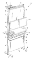
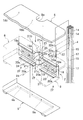
図1は、本発明の棚板の取付構造を有する什器の一実施形態を示す斜視図、図2は、要部を分解して示した図1に示す什器の斜視図、図3は、図2における破線円III内の拡大分解斜視図、図4は、図1におけるIV〜IV線断面図である。 1 is a perspective view showing an embodiment of a fixture having a shelf mounting structure according to the present invention, FIG. 2 is a perspective view of the fixture shown in FIG. 1 with its main parts disassembled, and FIG. FIG. 4 is an enlarged exploded perspective view in broken line circle III in FIG. 2, and FIG. 4 is a sectional view taken along line IV to IV in FIG.
図1に示す什器(1)は、前後方向を向く左右1対の脚台(2)(2)上に、それぞれ脚柱(3)(3)を立設し、この脚柱(3)(3)に、天井近くまで延びる支柱(4)(4)を連結し、この左右1対の支柱(4)(4)の上端部間に、横連結杆(5)を架設して形成されている。 The fixture (1) shown in FIG. 1 has pedestals (3) (3) standing on a pair of left and right pedestals (2) (2) facing in the front-rear direction. 3) is connected to the pillars (4) and (4) that extend close to the ceiling, and a horizontal connection rod (5) is installed between the upper ends of the left and right pairs of pillars (4) and (4). Yes.
天板(8)の上方において、左右の支柱(4)(4)間には、支持ビーム(12)が架設され、この支持ビーム(12)の前面には、モニター機器(13)が取付けられている。 Above the top plate (8), a support beam (12) is installed between the left and right support columns (4) and (4), and a monitor device (13) is attached to the front surface of the support beam (12). ing.
脚柱(3)(3)間には、コンセントボックス(6)が設けられ、その上方には、左右の支柱(4)(4)に取付けられたブラケット(7)(7)を介して、上下2枚の棚板(8)(9)が取付けられている。上部の棚板(8)は、天板として設計されており、この天板(8)と、下部の棚板(9)(以下、単に「棚板」という)間は、パソコン(10)などを収容しうる収容空間(11)となっている。 An outlet box (6) is provided between the pedestals (3) and (3), and the brackets (7) and (7) attached to the left and right columns (4) and (4) are provided above the outlet box (6). Two shelf boards (8) and (9) are attached on the top and bottom. The upper shelf board (8) is designed as a top board. Between this top board (8) and the lower shelf board (9) (hereinafter simply referred to as “shelf board”), a personal computer (10), etc. It is the accommodation space (11) which can accommodate the.
図3,図4に示すように、支柱(4)は、角管における4つの各側面(14)に、開口部(15)よりも奥部(16)が幅広の上下方向の奥幅広溝、本実施形態では特に魚尾状溝(17)を設けて形成されている。 As shown in FIGS. 3 and 4, the support column (4) is provided on each of the four side surfaces (14) of the square tube, and has a deep groove in the vertical direction in which the back part (16) is wider than the opening part (15). In the present embodiment, a fishtail groove (17) is provided in particular.
ブラケット(7)は、支柱(4)の対向面と平行をなし、前後方向に延びる基部(18)と、この基部(18)の上下端部より、それぞれ内側方に向けて連設された上下片(19)(20)とによって、正面視内向きコ字状に形成されている。 The bracket (7) is parallel to the opposing surface of the support column (4), and has a base (18) extending in the front-rear direction and upper and lower ends connected inward from the upper and lower ends of the base (18). By the pieces (19) and (20), it is formed in a U-shape in the front view.
基部(18)の前後方向の中央部には、外側方に向かって平面視台形状に膨出し、上下方向に開口する膨出部(21)が設けられている。この膨出部(21)の上下方向の開口(21b)を利用して、容易に、かつ体裁よく配線を行うことができる。膨出部(21)における支柱(4)と平行をなす取付片(21a)の上下端近傍には、挿通孔(21c)(21c)が設けられている。 A bulging portion (21) that bulges in a trapezoidal shape in plan view toward the outside and opens in the vertical direction is provided at the center portion in the front-rear direction of the base portion (18). By using the opening (21b) in the vertical direction of the bulging portion (21), wiring can be performed easily and with good appearance. Insertion holes (21c) and (21c) are provided in the vicinity of the upper and lower ends of the mounting piece (21a) parallel to the support column (4) in the bulging portion (21).
一方、支柱(4)の魚尾状溝(17)内には、上下方向に長手のねじ座(22)が挿入されている。ねじ座(22)の上下端近傍には、取付用のねじ孔(22a)(22a)が設けられている。この上下の取付用のねじ孔(22a)(22a)間には、位置決め用のねじ孔(22b)が設けられている。 On the other hand, a screw seat (22) elongated in the vertical direction is inserted into the fishtail-like groove (17) of the support post (4). Near the upper and lower ends of the screw seat (22), screw holes (22a) and (22a) for mounting are provided. A positioning screw hole (22b) is provided between the upper and lower mounting screw holes (22a) and (22a).
この位置決め用のねじ孔(22b)に、位置決め用ねじ(23)を螺合し、その先端(23a)を支柱(4)の魚尾状溝(17)における底部(17a)に圧接するとともに、ねじ座(22)を、魚尾状溝(17)における狭められた開口部(15)を形成する左右の開口舌片(15a)(15a)に内側から圧接させることにより、ねじ座(22)を仮固定して、上下方向の位置決めをなしうるようになっている。 The positioning screw (23) is screwed into the positioning screw hole (22b), and the tip (23a) is pressed against the bottom (17a) of the fishtail groove (17) of the support column (4), and the screw The screw seat (22) is temporarily attached by pressing the seat (22) from the inside to the left and right opening tongues (15a) (15a) forming the narrowed opening (15) in the fishtail groove (17). It can be fixed and positioned in the vertical direction.
このようにして位置決めしたねじ座(22)の上下の取付用のねじ孔(22a)(22a)に、それぞれ取付用ねじ(24)(24)を、ブラケット(7)における取付片(21a)の挿通孔(21c)(21c)を介して螺合し、取付片(21a)とねじ座(22)の両者をもって、支柱(4)における開口部(15)の左右の開口舌片(15a)(15a)を挟持することにより、ブラケット(7)を支柱(4)に取付けてある。 The mounting screws (24) and (24) are respectively attached to the upper and lower mounting screw holes (22a) and (22a) of the screw seat (22) thus positioned, and the mounting pieces (21a) of the bracket (7) are mounted. Screwed through the insertion holes (21c) and (21c), both the mounting piece (21a) and the screw seat (22), and the left and right opening tongues (15a) (15a) ( The bracket (7) is attached to the column (4) by clamping 15a).
なお、ブラケット(7)における取付片(21a)には、外側方に向かう係合突起(25)が設けられており、この係合突起(25)を魚尾状溝(17)内に係合させて、ブラケット(7)の前後方向のずれを防止するようにしてある。 The mounting piece (21a) of the bracket (7) is provided with an engaging protrusion (25) directed outward, and this engaging protrusion (25) is engaged in the fishtail groove (17). The bracket (7) is prevented from shifting in the front-rear direction.
左右のブラケット(7)(7)における上片(19)には天板(8)、下片(20)には棚板(9)のそれぞれの左右端部が固定される。 The left and right ends of the top plate (8) and the shelf (9) are fixed to the upper piece (19) and the lower piece (20) of the left and right brackets (7) and (7), respectively.
天板(8)の左右端における前後方向の中央には、半円弧状の切欠き(8a)(8a)が設けられている。この切欠き(8a)(8a)を、左右の支柱(4)(4)に嵌合して、左右のブラケット(7)(7)の上片(19)(19)上に載置したのち、止めねじ(26)(26)を、上片(19)に穿設した通孔(19a)を介して、天板(8)の裏面に設けたねじ孔(18b)に螺合することにより、天板(8)はブラケット(7)に取付けられている。 In the center in the front-rear direction at the left and right ends of the top plate (8), semicircular cutouts (8a) and (8a) are provided. After fitting these notches (8a) and (8a) into the left and right support posts (4) and (4) and placing them on the upper pieces (19) and (19) of the left and right brackets (7) and (7), By screwing the set screws (26) and (26) into the screw holes (18b) provided on the back surface of the top plate (8) through the through holes (19a) formed in the upper piece (19). The top plate (8) is attached to the bracket (7).
天板(8)の左右端の切欠き(8a)(8a)と支柱(4)間には、三日月状の間隙(27)が残されており、この間隙(27)は、ブラケット(7)の膨出部(21)における上下方向の開口(21b)と連通しており、配線に利用しうるようになっている。 A crescent-shaped gap (27) is left between the notches (8a) (8a) and the support posts (4) at the left and right ends of the top plate (8). The gap (27) It communicates with the opening (21b) in the vertical direction in the bulging portion (21) of the bulge and can be used for wiring.
棚板(9)も同様にして、その左右端を、左右のブラケット(7)(7)の下片(20)(20)上に載置したのち、止めねじ(27)(27)を、下片(20)に穿設した通孔(20a)を介して、棚板(9)に設けたねじ孔(9a)に螺合することにより、ブラケット(7)に取付けられている。天板(8)と棚板(9)間には、ブラケット(7)の上下方向の幅から棚板の厚み分小さい寸法と、ほぼ同一の上下間隔を有する収容空間(11)が形成されており、パソコン(10)等を収容しうるようになっている。 Similarly, the left and right ends of the shelf board (9) are placed on the lower pieces (20) and (20) of the left and right brackets (7) and (7), and then the set screws (27) and (27) are attached. It is attached to the bracket (7) by screwing into a screw hole (9a) provided in the shelf plate (9) through a through hole (20a) drilled in the lower piece (20). Between the top plate (8) and the shelf plate (9), an accommodation space (11) having a dimension that is smaller than the vertical width of the bracket (7) by the thickness of the shelf plate and substantially the same vertical spacing is formed. It can accommodate a personal computer (10) and the like.
ブラケット(7)の前後方向の長さを、棚板(9)の前後方向の長さとほぼ同一として、前記収容空間(11)の左右側方を閉塞してある。 The length of the bracket (7) in the front-rear direction is substantially the same as the length of the shelf plate (9) in the front-rear direction, and the left and right sides of the housing space (11) are closed.
図5は、図1におけるV〜V線断面図である。
図5に示すように、左右の角管状の支柱(4)(4)における4つの各側面(14)には、配線ダクト(28)が添設されている。配線ダクト(28)は、上下方向に延びる基板(28a)の両側縁を斜め外側へ向かって折り曲げた後、両遊端(28b)(28b)が近接する弧状片(28c)(28c)を連設するとともに、基板(28a)の内側面に、外向きの係止爪(28d)(28d)を有する1対の上下方向の係止片(28e)(28e)を設け、かつ基板(28a)の外側面の中央に、上下方向の突起片(28f)を設けて形成されている。
5 is a cross-sectional view taken along line V-V in FIG.
As shown in FIG. 5, a wiring duct (28) is attached to each of the four side surfaces (14) of the left and right square tubular columns (4) (4). The wiring duct (28) is connected to the arc-shaped pieces (28c) (28c) adjacent to both free ends (28b) (28b) after bending both side edges of the board (28a) extending in the vertical direction diagonally outward. And a pair of vertical locking pieces (28e) (28e) having outward locking claws (28d) (28d) are provided on the inner surface of the substrate (28a), and the substrate (28a) A protrusion piece (28f) in the vertical direction is provided at the center of the outer surface of the upper and lower surfaces.
この配線ダクト(28)は、その基板(28a)の外側面に設けられた1対の係止片(28e)(28e)を、支柱(4)の側面(14)における開口部が挟められた魚尾状溝(17)に係合させて、支柱(4)に着脱可能に添設されている。 In this wiring duct (28), a pair of locking pieces (28e) (28e) provided on the outer side surface of the substrate (28a) is sandwiched between openings on the side surface (14) of the column (4). It engages with the fishtail groove (17) and is detachably attached to the support post (4).
左右の支柱(4)(4)の上端部間に架設した横連結杆(5)には、天井等から電源用の配線を支持するための配線受け(29)が取付けられている。 A wiring receiver (29) for supporting power supply wiring from the ceiling or the like is attached to the horizontal connection rod (5) installed between the upper ends of the left and right columns (4) and (4).
(1)什器
(2)脚台
(3)脚柱
(4)支柱
(5)横連結杆
(6)コンセントボックス
(7)ブラケット
(8)天板(棚板)
(8a)切欠き
(8b)ねじ孔
(9)棚板
(9a)ねじ孔
(10)パソコン
(11)収容空間
(12)支持ビーム
(13)モニター機器
(14)側面
(15)開口部
(15a)開口舌片
(16)奥部
(17)魚尾状溝(奥幅広溝)
(17a)底部
(18)基部
(19)上片
(19a)通孔
(20)下片
(20a)通孔
(21)膨出部
(21a)取付片
(21b)開口
(21c)挿通孔
(22)ねじ座
(22a)(22b)ねじ孔
(23)位置決め用ねじ
(23a)先端
(24)取付用ねじ
(25)係合突起
(26)(27)止めねじ
(28)配線ダクト
(29)配線受け
(1) Furniture
(2) Footrest
(3) pedestal
(4) Prop
(5) Horizontal connection rod
(6) Outlet box
(7) Bracket
(8) Top plate (shelf)
(8a) Notch
(8b) Screw hole
(9) Shelf board
(9a) Screw hole
(10) PC
(11) Containment space
(12) Support beam
(13) Monitor equipment
(14) Side
(15) Opening
(15a) Open tongue
(16) Back
(17) Fishtail groove (back wide groove)
(17a) Bottom
(18) Base
(19) Upper piece
(19a) Through hole
(20) Lower piece
(20a) Through hole
(21) bulge
(21a) Mounting piece
(21b) Opening
(21c) Insertion hole
(22) Screw seat
(22a) (22b) Screw hole
(23) Positioning screw
(23a) Tip
(24) Mounting screw
(25) Engagement protrusion
(26) (27) Set screw
(28) Wiring duct
(29) Wiring receiver
Claims (4)
両支柱の対向面に、開口部より奥部が幅広の奥幅広溝を上下方向に形成して、この奥幅広溝内にねじ座を挿入し、ブラケットに穿設した挿通孔を介して、取付用ねじをねじ座に螺合することにより、ブラケットを支柱に固定するとともに、ブラケットを、支柱の対向面と平行をなし、前後方向に延びる基部と、基部の上下端部より、それぞれ左右方向の内方に向けて連設した上下片とによって、正面視内向きコ字状に形成し、かつ左右のブラケットにおける上片および下片に、それぞれ棚板の左右端部を固定して、上下の棚板間に収容空間を形成するものとし、ブラケットの前後方向の長さを、左右のブラケットの下片に両端部が固定される下部棚板の前後方向の長さとほぼ同一として、上下の棚板間の収容空間の左右側方を閉塞したことを特徴とする棚板の取付構造。 In the mounting structure of the shelf board between a pair of left and right columns in furniture used in offices and nurse stations,
On the opposing surfaces of both struts, a deep wide groove with a depth wider than the opening is formed in the vertical direction, and a screw seat is inserted into the deep wide groove and attached via an insertion hole drilled in the bracket. The bracket is fixed to the column by screwing the screw to the screw seat, and the bracket is parallel to the opposite surface of the column and extends in the front-rear direction, and from the upper and lower ends of the base in the left-right direction. The upper and lower pieces arranged inward are formed in an inward U shape in front view, and the left and right ends of the shelf are fixed to the upper and lower pieces of the left and right brackets, respectively. The storage space shall be formed between the shelves, and the length of the brackets in the front-rear direction shall be substantially the same as the length of the lower shelves whose both ends are fixed to the lower pieces of the left and right brackets. that closes the left and right sides of the accommodation space between the plates Mounting structure of the shelf plate to symptoms.
両支柱の対向面に、開口部より奥部が幅広の奥幅広溝を上下方向に形成して、この奥幅広溝内にねじ座を挿入し、ブラケットに穿設した挿通孔を介して、取付用ねじをねじ座に螺合することにより、ブラケットを支柱に固定するとともに、ブラケットを、支柱の対向面と平行をなし、前後方向に延びる基部と、基部の上下端部より、それぞれ左右方向の内方に向けて連設した上下片とによって、正面視内向きコ字状に形成し、かつ左右のブラケットにおける上片および下片に、それぞれ棚板の左右端部を固定して、上下の棚板間に収容空間を形成するものとし、ねじ座に、位置決め用ねじを螺合するためのねじ孔を設け、このねじ孔に螺合した位置決め用ねじの遊端を、支柱における奥幅広溝の底部に圧接するとともに、奥幅広溝内に挿入したねじ座を、奥幅広溝における狭められた開口部を形成する左右の開口舌片に内側から圧接させて、ねじ座を仮固定することにより、このねじ座に取付けられるブラケットの取付けの位置決めを可能とするようにしたことを特徴とする棚板の取付構造。 In the mounting structure of the shelf board between a pair of left and right columns in furniture used in offices and nurse stations,
On the opposing surfaces of both struts, a deep wide groove with a depth wider than the opening is formed in the vertical direction, and a screw seat is inserted into the deep wide groove and attached via an insertion hole drilled in the bracket. The bracket is fixed to the column by screwing the screw to the screw seat, and the bracket is parallel to the opposite surface of the column and extends in the front-rear direction, and from the upper and lower ends of the base in the left-right direction. The upper and lower pieces arranged inward are formed in an inward U shape in front view, and the left and right ends of the shelf are fixed to the upper and lower pieces of the left and right brackets, respectively. An accommodation space is to be formed between the shelf plates . A screw hole for screwing a positioning screw is provided in the screw seat, and the free end of the positioning screw screwed into the screw hole is connected to the wide groove in the column. And press it into the bottom wide groove. It is possible to position the mounting of the bracket attached to this screw seat by pressing the screw seat from the inside to the left and right opening tongues that form the narrowed opening in the deep wide groove and temporarily fixing the screw seat. mounting structure for to that shelf board, characterized in that as a.
両支柱の対向面に、開口部より奥部が幅広の奥幅広溝を上下方向に形成して、この奥幅広溝内にねじ座を挿入し、ブラケットに穿設した挿通孔を介して、取付用ねじをねじ座に螺合することにより、ブラケットを支柱に固定するとともに、ブラケットを、支柱の対向面と平行をなし、前後方向に延びる基部と、基部の上下端部より、それぞれ左右方向の内方に向けて連設した上下片とによって、正面視内向きコ字状に形成し、かつ左右のブラケットにおける上片および下片に、それぞれ棚板の左右端部を固定して、上下の棚板間に収容空間を形成するものとし、ブラケットにおける基部の前後方向の中央部に、左右方向の外方に向かって膨出し、上下方向に開口することにより、配線空間として使用しうるようにした膨出部を設けたことを特徴とする棚板の取付構造。 In the mounting structure of the shelf board between a pair of left and right columns in furniture used in offices and nurse stations,
On the opposing surfaces of both struts, a deep wide groove with a depth wider than the opening is formed in the vertical direction, and a screw seat is inserted into the deep wide groove and attached via an insertion hole drilled in the bracket. The bracket is fixed to the column by screwing the screw to the screw seat, and the bracket is parallel to the opposite surface of the column and extends in the front-rear direction, and from the upper and lower ends of the base in the left-right direction. The upper and lower pieces arranged inward are formed in an inward U shape in front view, and the left and right ends of the shelf are fixed to the upper and lower pieces of the left and right brackets, respectively. An accommodation space is to be formed between the shelf boards, and it can be used as a wiring space by bulging outward in the left-right direction at the center in the front-rear direction of the base of the bracket and opening in the vertical direction. Patent in that a the bulging portion Mounting structure for to that shelves and.
Priority Applications (1)
| Application Number | Priority Date | Filing Date | Title |
|---|---|---|---|
| JP2005324122A JP4763426B2 (en) | 2005-11-08 | 2005-11-08 | Mounting structure of shelf board, and fixtures for nurse stations equipped with this shelf board |
Applications Claiming Priority (1)
| Application Number | Priority Date | Filing Date | Title |
|---|---|---|---|
| JP2005324122A JP4763426B2 (en) | 2005-11-08 | 2005-11-08 | Mounting structure of shelf board, and fixtures for nurse stations equipped with this shelf board |
Publications (2)
| Publication Number | Publication Date |
|---|---|
| JP2007130095A JP2007130095A (en) | 2007-05-31 |
| JP4763426B2 true JP4763426B2 (en) | 2011-08-31 |
Family
ID=38152256
Family Applications (1)
| Application Number | Title | Priority Date | Filing Date |
|---|---|---|---|
| JP2005324122A Expired - Fee Related JP4763426B2 (en) | 2005-11-08 | 2005-11-08 | Mounting structure of shelf board, and fixtures for nurse stations equipped with this shelf board |
Country Status (1)
| Country | Link |
|---|---|
| JP (1) | JP4763426B2 (en) |
Families Citing this family (3)
| Publication number | Priority date | Publication date | Assignee | Title |
|---|---|---|---|---|
| JP2016016239A (en) * | 2014-07-10 | 2016-02-01 | 株式会社岡村製作所 | furniture |
| JP2016016240A (en) * | 2014-07-10 | 2016-02-01 | 株式会社岡村製作所 | furniture |
| WO2018012493A1 (en) * | 2016-07-11 | 2018-01-18 | 株式会社岡村製作所 | Article of furniture |
Family Cites Families (3)
| Publication number | Priority date | Publication date | Assignee | Title |
|---|---|---|---|---|
| JPS425555Y1 (en) * | 1964-10-20 | 1967-03-20 | ||
| JP2002227436A (en) * | 2001-02-02 | 2002-08-14 | Kokuyo Co Ltd | Structural body |
| JP4319518B2 (en) * | 2003-10-30 | 2009-08-26 | 株式会社岡村製作所 | Table with shelf |
-
2005
- 2005-11-08 JP JP2005324122A patent/JP4763426B2/en not_active Expired - Fee Related
Also Published As
| Publication number | Publication date |
|---|---|
| JP2007130095A (en) | 2007-05-31 |
Similar Documents
| Publication | Publication Date | Title |
|---|---|---|
| TW202114504A (en) | Rack assembly | |
| JP4763426B2 (en) | Mounting structure of shelf board, and fixtures for nurse stations equipped with this shelf board | |
| JP5516517B2 (en) | Desktop panel mounting device | |
| JP4274065B2 (en) | Mounting device for supporting member | |
| TWI402430B (en) | Fixed fitting for connecting a equipment unit to a rack | |
| JP5520059B2 (en) | Rack base and double floor structure | |
| JP6163764B2 (en) | Table wiring duct equipment | |
| JP5927651B2 (en) | Side plate mounting brackets for electrical and electronic equipment storage boxes | |
| JP2006187401A (en) | Assembly type enclosure | |
| JP2010035935A (en) | Counter apparatus | |
| JP5193968B2 (en) | Wiring holder | |
| JP2009261841A5 (en) | ||
| JP2009261841A (en) | Attachment device of desk panel | |
| JP6795949B2 (en) | table | |
| JP4388507B2 (en) | Storage rack | |
| JP5337003B2 (en) | desk | |
| WO2017213220A1 (en) | Wiring accommodation fixture | |
| JP5148193B2 (en) | Desk with shelf | |
| JP5917585B2 (en) | Storage unit | |
| US20230007795A1 (en) | Extension kit | |
| JP2010273743A (en) | Display shelf and mounting structure of display shelf | |
| JP2009261821A (en) | Workstation | |
| JP2011151907A (en) | Wiring cover mounting structure | |
| JP2020071272A (en) | Display stand | |
| JP2022070666A (en) | furniture |
Legal Events
| Date | Code | Title | Description |
|---|---|---|---|
| A621 | Written request for application examination |
Free format text: JAPANESE INTERMEDIATE CODE: A621 Effective date: 20080930 |
|
| A977 | Report on retrieval |
Free format text: JAPANESE INTERMEDIATE CODE: A971007 Effective date: 20100827 |
|
| A131 | Notification of reasons for refusal |
Free format text: JAPANESE INTERMEDIATE CODE: A131 Effective date: 20110118 |
|
| A521 | Written amendment |
Free format text: JAPANESE INTERMEDIATE CODE: A523 Effective date: 20110307 |
|
| TRDD | Decision of grant or rejection written | ||
| A01 | Written decision to grant a patent or to grant a registration (utility model) |
Free format text: JAPANESE INTERMEDIATE CODE: A01 Effective date: 20110607 |
|
| A01 | Written decision to grant a patent or to grant a registration (utility model) |
Free format text: JAPANESE INTERMEDIATE CODE: A01 |
|
| A61 | First payment of annual fees (during grant procedure) |
Free format text: JAPANESE INTERMEDIATE CODE: A61 Effective date: 20110609 |
|
| FPAY | Renewal fee payment (event date is renewal date of database) |
Free format text: PAYMENT UNTIL: 20140617 Year of fee payment: 3 |
|
| R150 | Certificate of patent or registration of utility model |
Free format text: JAPANESE INTERMEDIATE CODE: R150 |
|
| R250 | Receipt of annual fees |
Free format text: JAPANESE INTERMEDIATE CODE: R250 |
|
| R250 | Receipt of annual fees |
Free format text: JAPANESE INTERMEDIATE CODE: R250 |
|
| R250 | Receipt of annual fees |
Free format text: JAPANESE INTERMEDIATE CODE: R250 |
|
| R250 | Receipt of annual fees |
Free format text: JAPANESE INTERMEDIATE CODE: R250 |
|
| LAPS | Cancellation because of no payment of annual fees |