JP2016016239A - furniture - Google Patents
furniture Download PDFInfo
- Publication number
- JP2016016239A JP2016016239A JP2014142563A JP2014142563A JP2016016239A JP 2016016239 A JP2016016239 A JP 2016016239A JP 2014142563 A JP2014142563 A JP 2014142563A JP 2014142563 A JP2014142563 A JP 2014142563A JP 2016016239 A JP2016016239 A JP 2016016239A
- Authority
- JP
- Japan
- Prior art keywords
- top plate
- support
- end side
- fixture
- frame
- Prior art date
- Legal status (The legal status is an assumption and is not a legal conclusion. Google has not performed a legal analysis and makes no representation as to the accuracy of the status listed.)
- Pending
Links
Images

Abstract
Description
本発明は、什器に関する。 The present invention relates to a fixture.
オフィス、公共施設、病院等の執務空間においては、各種作業を行うため、テーブル、デスク等の什器が用いられている。このような什器においては、作業面を形成する天板上で十分な作業スペースを確保するため、天板以外に、各種の物品を載置する棚板等が設けられている。 In office spaces such as offices, public facilities, and hospitals, fixtures such as tables and desks are used to perform various operations. In such a fixture, in order to secure a sufficient work space on the top plate forming the work surface, in addition to the top plate, a shelf plate for placing various articles is provided.
特許文献1、2には、天板を支持する左右の脚体と、左右の脚体上にそれぞれ設けられ、上方に向けて延びるオプション部材取付用の支持杆と、天板の後端部に設けられ、左右の支持杆の間に架設された横杆と、横杆から前方に延びるように設けられた棚板やキャビネットと、を備える構成が開示されている。
これらの構成によれば、物品を棚板やキャビネットに載置したり収納したりすることで、天板上の作業スペースを十分に確保することができている。
In Patent Documents 1 and 2, left and right legs for supporting the top plate, support rods for attaching optional members provided on the left and right legs respectively and extending upward, and a rear end portion of the top plate A configuration is disclosed that includes a horizontal rail provided between left and right support rods, and a shelf board and a cabinet provided so as to extend forward from the horizontal rail.
According to these structures, the work space on a top plate can fully be ensured by mounting | wearing with or storing an article | item on a shelf board or a cabinet.
しかしながら、特許文献1,2に開示された構成においては、棚板やキャビネットが支持杆、横杆から前方に向けて延びるように設けられている。したがって、棚板やキャビネットで支持する物品による荷重のモーメントが、支持杆の根元部分に集中して作用する。
例えば、近年のナースステーションにおいては、複数のディスプレイやプリンタ等の各種の機器を、棚板やキャビネットで支持する必要がある。これにより、支持杆の根元部分に作用する荷重によるモーメントが非常に大きくなるため、支持杆を、大きな荷重モーメントに抗するよう強固に設ける必要がある。支持杆を強固に設けるには、支持杆の断面積を大きくしたり、支持杆を固定するボルトの本数を増やしたりする必要があるが、これでは什器のコストが増大してしまう。
そこでなされた本発明の目的は、十分な物品の支持強度を有しつつ、低コスト化を図ることができる什器を提供することである。
However, in the configurations disclosed in Patent Documents 1 and 2, shelf boards and cabinets are provided so as to extend forward from the support rods and the reeds. Therefore, the moment of load due to the article supported by the shelf board or cabinet acts on the root portion of the support rod.
For example, in a nurse station in recent years, various devices such as a plurality of displays and printers need to be supported by a shelf board or a cabinet. As a result, the moment due to the load acting on the root portion of the support rod becomes very large, and therefore it is necessary to provide the support rod firmly against a large load moment. In order to provide the support rod firmly, it is necessary to increase the cross-sectional area of the support rod or increase the number of bolts for fixing the support rod. However, this increases the cost of the fixture.
An object of the present invention made there is to provide a fixture capable of reducing the cost while having sufficient support strength of an article.
本発明は、上記課題を解決するため、以下の手段を採用する。
この発明に係る什器は、作業面を形成する天板と、前記天板の一端側と他端側とにそれぞれ設けられた支持フレームと、前記天板の前記一端側と前記他端側とを結ぶ方向に延び、前記支持フレームの上部どうしを連結する連結フレームと、を備え、前記支持フレームは、前記天板における前記一端側と前記他端側を結ぶ方向に直交する方向の両側に配置され、床面から上方に向けて延びる二本一対の支柱と、前記二本一対の前記支柱の上部どうしを連結する上部連結部材と、を備え、前記天板は、前記二本一対の前記支柱に、前記上部連結部材よりも下方位置で固定されていることを特徴とする。
The present invention employs the following means in order to solve the above problems.
The fixture according to the present invention includes a top plate forming a work surface, a support frame provided on one end side and the other end side of the top plate, and the one end side and the other end side of the top plate. A connecting frame that extends in the connecting direction and connects the upper portions of the supporting frames, and the supporting frames are arranged on both sides of the top plate in a direction orthogonal to the direction connecting the one end side and the other end side. A pair of two columns extending upward from the floor surface, and an upper connecting member that couples upper portions of the two pairs of columns, and the top plate is attached to the two pairs of columns. The upper connecting member is fixed at a position below the upper connecting member.
このような什器によれば、支持フレームは、二本一対の支柱の上端部どうしが上部連結部材によって連結されることで門型をなし、さらに上部連結部材よりも下方位置で、二本一対の支柱の間に配置された天板が両側の支柱に固定されている。これにより、支持フレームは、二本一対の支柱どうしが、上部連結部材と天板とによって連結されることとなるため、支柱の上部どうしが離間することを上部連結部材が拘束するとともに、支柱における上部連結部材よりも下方位置どうしが離間することを天板が拘束する。よって、支持フレームにおいて支柱どうしが離間する方向(天板における一端側と他端側とを結ぶ方向に直交する方向)に沿う面における剛性を高めることができるため、高い強度を確保することができる。
さらに、天板の一端側と他端側とに配置された支持フレームは、その上部どうしが連結フレームで連結されるのに加え、連結フレームよりも下方位置で天板によっても固定される。したがって、一対の支持フレームどうしが互いに離間する方向に沿う面の剛性も高めることができるため、什器全体が高強度を有したものとなる。
このような什器では、連結フレームや支持フレームで物品の荷重を支持する場合、支柱の特定の部位に荷重が集中するのを抑えることができ、支柱の断面積を大きくしたり支柱の基端部を強固に固定することなく、什器全体で効率良く荷重を支持することができる。
According to such a fixture, the support frame is formed in a gate shape by connecting the upper ends of the two pairs of struts by the upper connecting member, and further, the pair of two pairs at a position below the upper connecting member. A top plate arranged between the columns is fixed to the columns on both sides. As a result, since the pair of support columns are connected to each other by the upper connecting member and the top plate, the upper connecting member restrains the upper portions of the support members from being separated from each other, and The top plate restrains the positions below the upper connecting member to be separated from each other. Therefore, since the rigidity in the surface along the direction in which the support columns are separated from each other in the support frame (the direction perpendicular to the direction connecting the one end side and the other end side of the top plate) can be increased, high strength can be ensured. .
Furthermore, the support frames arranged on one end side and the other end side of the top plate are fixed by the top plate at a position below the connection frame in addition to the upper portions being connected by the connection frame. Therefore, since the rigidity of the surface along the direction in which the pair of support frames are separated from each other can be increased, the entire fixture has high strength.
In such a fixture, when the load of an article is supported by a connecting frame or a support frame, the load can be prevented from concentrating on a specific part of the column, and the cross-sectional area of the column can be increased or the base end of the column The load can be efficiently supported by the entire fixture without being firmly fixed.
また、前記連結フレームおよび前記上部連結部材の少なくとも一方が、オプション部材を取付可能なオプション部材取付部を備えるようにしてもよい。
これにより、連結フレームや上部連結部材に、オプション部材を取り付けることができる。そして、オプション部材取付部に取り付けたオプション部材の荷重を、支柱や天板を含めた什器全体で支持することができる。
また、連結フレームや上部連結部材は高い位置にあるため、オプション部材を遠方から容易に視認することが可能となる。
In addition, at least one of the connection frame and the upper connection member may include an option member attaching portion to which an option member can be attached.
Thereby, an option member can be attached to a connection frame or an upper connection member. And the load of the option member attached to the option member attaching part can be supported by the whole fixture including a support | pillar and a top plate.
Further, since the connection frame and the upper connection member are at a high position, the option member can be easily visually recognized from a distance.
また、前記支柱は、配線を収容可能な配線収容空間を有しているようにしてもよい。
これにより、什器で支持する機器類の配線を配線収容空間に収容することで、配線が露出して外観が損なわれるのを防ぐことができる。
Further, the support column may have a wiring housing space capable of housing the wiring.
Thereby, by accommodating the wiring of the devices supported by the furniture in the wiring housing space, it is possible to prevent the wiring from being exposed and the appearance from being damaged.
また、前記二本一対の前記支柱間には、物品を載置可能な棚板が設けられているようにしてもよい。
これにより、各種機器等の物品を棚板上に載置することができ、その荷重を、強固な門型フレームを構成する支柱で確実に支持することができる。
Further, a shelf plate on which an article can be placed may be provided between the two pairs of columns.
Thereby, articles, such as various apparatuses, can be mounted on a shelf board, and the load can be reliably supported with the support | pillar which comprises a firm portal frame | frame.
この発明に係る什器によれば、連結フレームや支持フレームで物品の荷重を支持する場合に特定の部位に荷重が集中するのを抑え、什器全体で効率良く荷重を支持することができる。したがって、集中する荷重に抗するために支柱の特定の部位を強固にする必要がなく、支柱の断面積を大きくしたり支柱の基端部を強固に固定することなく、十分な支持強度を有しつつ低コスト化を図ることが可能となる。 According to the fixture according to the present invention, when the load of the article is supported by the connecting frame or the support frame, it is possible to suppress the load from being concentrated on a specific portion, and the load can be efficiently supported by the entire fixture. Therefore, there is no need to strengthen a specific part of the column in order to resist concentrated loads, and there is sufficient support strength without increasing the column cross-sectional area or firmly fixing the base end of the column. However, the cost can be reduced.
以下、添付図面を参照して、本発明による什器を実施するための形態を説明する。しかし、本発明はこれらの実施形態のみに限定されるものではない。 Hereinafter, with reference to an accompanying drawing, a form for carrying out a fixture by the present invention is explained. However, the present invention is not limited only to these embodiments.
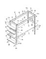
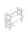
図1は、この発明の一実施形態に係る什器の全体構成を示す斜視図である。
図1に示すように、什器10は、平面視長方形状の天板11と、天板11の長手方向の両端部にそれぞれ配置された一対の支持フレーム20,30と、一対の支持フレーム20,30どうしを連結する一対の連結フレーム50,50と、を備えている。
ここで、以下の説明において、天板11の長手方向(天板11の一端側11aと他端側11bとを結ぶ方向)を「幅方向」、天板11の短手方向を「前後方向」(天板11の一端側11aと他端側11bとを結ぶ方向に直交する方向)とする。
FIG. 1 is a perspective view showing an overall configuration of a fixture according to an embodiment of the present invention.
As shown in FIG. 1, the
Here, in the following description, the longitudinal direction of the top plate 11 (the direction connecting the one
一方の支持フレーム20は、床面上に設置され、床面から上方に向けて延びる二本一対の支柱21,21と、これら支柱21,21の上端部21a,21aどうしを連結する上部連結部材26と、を備えている。二本一対の支柱21,21は、前後方向に沿って間隔をあけて配置されている。
One
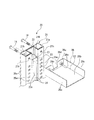
図2は、上記什器における支柱と上部連結部材との構成を示す斜視図である。
図2に示すように、各支柱21には、上下方向に連続する配線収容空間E1が内部に形成されている。支柱21において、対向する支柱21に面した側の側面には、上下方向に亘って内方に凹となる溝部22が形成されている。溝部22内には、スリット23sが形成された断面略C型状の長尺なチャンネル部材23が嵌合されている。このチャンネル部材23内の空間が、配線収容空間E1となる。このチャンネル部材23には、スリット23sを塞ぐ軟質なシート状の塞ぎ部材24が設けられている。塞ぎ部材24は、ゴム等の柔らかい材料で形成された可撓性の部材であり、一端側がチャンネル部材23に固定され、他端側が自由端となっている。そのため、塞ぎ部材24を変形させて、配線収容空間E1に配線を必要時に出し入れすることができるようになっている。この塞ぎ部材24は、溝部22のスリット23sを塞ぐ部材として機能する。
FIG. 2 is a perspective view showing the configuration of the support and the upper connecting member in the fixture.
As shown in FIG. 2, each
支柱21において、対向する支柱21に面した側の側面には、溝部22の両側に、それぞれ上下方向に一定の間隔をあけて複数の係合孔25mが形成されている。また、支柱21において、対向する支柱21に面した側とは反対の側面には、上下方向に一定の間隔をあけて複数のスリット25sが形成されている。
また、支柱21の上端部21aには、対向する支柱21と対向する側の内側面及び反対側の外側面に、それぞれボルト挿通孔21hが形成されている。
In the
Moreover, 21 h of bolt insertion holes are formed in the
上部連結部材26は、平面視長方形状の底板部26bと、底板部26bの外周部から上方に立ち上がる壁部26c,26c…と、を有した有底状をなしている。上部連結部材26の支柱21に対向する壁部26cには、下方に凹む凹部26dが形成されている。上部連結部材26の底板部26bと天板11の幅方向に対向する壁部26c,26cとに囲まれて、配線収容空間E2が形成されている。この配線収容空間E2内に、支柱21の配線収容空間E1の上端から導出された配線を、凹部26dを通して収容できるようになっている。
The upper connecting
上部連結部材26の前後方向の両端部において、それぞれ支柱21に対向する壁部26cには、凹部26dの幅方向両側に雌ネジ部26nが形成されている。支柱21の外側面のボルト挿通孔21hから挿通されたボルト14の先端部は、内側面のボルト挿通孔21hを通して上部連結部材26の雌ネジ部26nに締結される。これにより、上部連結部材26は支柱21の上端部21aに連結されている。
At both ends in the front-rear direction of the upper connecting
図1に示すように、このような支持フレーム20は、二本一対の支柱21,21が、上端部の上部連結部材26のほかに、少なくとも一つの下部連結部材27によって連結されている。
この実施形態において、下部連結部材27として、天板11の下方に配置された幕板28が設けられている。幕板28は、二本一対の支柱21,21間で、上下方向に一定長を有した矩形板状をなしている。この幕板28は、図示しないボルト等によって、両側の支柱21,21にそれぞれ連結されている。また、幕板28は、その前後方向両端部に、支柱21側から天板11の下面に沿って天板11の幅方向内方に向けて延びる補強板部28rを備えている。
このようにして、支持フレーム20は、二本一対の支柱21、21が、上部連結部材26と下部連結部材27とによって連結され、矩形状、梯子状をなしている。
As shown in FIG. 1, in this
In this embodiment, a
In this manner, the
支持フレーム20の下端部には、床面に沿って延びる脚部20fが設けられている。
また、支持フレーム20には、上下に間隔をあけて複数枚の棚板29が設けられている。
さらに、支持フレーム20には、ディスプレイモニタ等のオプション部材90を装着可能なオプション部材取付バー40が設けられている。
これらの脚部20f、棚板29、オプション部材取付バー40は、それぞれの両端部が、支柱21,21に形成されたスリット25s(図2参照)に、図示しない係止フックを係止させることで固定されている。ここで、脚部20f、棚板29は、什器10の幅方向外方に向けて突出するよう設けられている。
A
In addition, the
Further, the
The
他方の支持フレーム30は、床面上に設置され、床面から上方に向けて延びる二本一対の支柱31,31と、これら支柱31,31の上端部31a,31aどうしを連結する上部連結部材36と、を備えている。
The
二本一対の支柱31,31は、前後方向に沿って間隔をあけて配置されている。各支柱31は、上下方向に連続する平面視略矩形の筒状で、その内部に配線等を挿通できる配線収容空間(図示無し)を備えている。
The two pairs of
上部連結部材36の両端部は、それぞれ図示しないブラケットやボルトによって、支柱31の上端部31aに連結されている。
上部連結部材36における天板11の幅方向の両面には、上下に間隔をあけて複数の係止溝(オプション部材取付部)38,38が形成されている。
Both ends of the upper connecting
A plurality of locking grooves (option member mounting portions) 38, 38 are formed on both surfaces of the top connecting
また、このような支持フレーム30は、二本一対の支柱31,31が、上部連結部材36のほかに、少なくとも一つの下部連結部材37によって連結されている。
この実施形態において、下部連結部材37は、天板11の下方に配置されている。下部連結部材37は、図示しないボルト等によって、両側の支柱31,31にそれぞれ連結されている。
このようにして、支持フレーム30は、二本一対の支柱31,31が、上部連結部材36と下部連結部材37とによって連結され、矩形状、梯子状をなしている。
Further, in such a
In this embodiment, the lower connecting
In this manner, the
支持フレーム30には、支持フレーム20と同様に、ディスプレイモニタ等のオプション部材90を装着可能なオプション部材取付バー40が設けられている。オプション部材取付バー40は、それぞれの両端部が、支柱31,31に連結固定されている。
Similar to the
天板11は、その上面に水平な作業面11fを有している。天板11は、長手方向の一端側11aおよび他端側11bが、支持フレーム20の下部連結部材27、支持フレーム30の下部連結部材37の上に載置されている。そして、天板11は、下部連結部材27、37に、図示しないボルト等を用いて連結固定されている。これにより、天板11は、下部連結部材27、37を介し、支柱21,21、31,31に固定されている。
また、天板11は、支柱21,31を収容する凹部12が、天板11の前後方向両側にそれぞれ形成されている。そして、天板11は、他端側11bの端部11sが、什器10の幅方向外方に向けて突出するよう設けられている。
The
Further, the
連結フレーム50は、支持フレーム20と支持フレーム30に対し、前後方向の両側それぞれに、天板11の幅方向に延びるように配置されている。連結フレーム50は、支持フレーム20,30の前後方向両側にそれぞれ配置された支柱21,31に、図示しないブラケットやボルトを用いて連結されている。
The
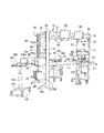
図3は、上記什器を構成する連結フレームの断面図である。
図3に示すように、連結フレーム50は、前後方向に間隔をあけて配置された側板部50a,50aと、これら側板部50a,50aを連結する連結板部50b,50b…と、を備えている。連結板部50bは、側板部50a,50aの上下の端部よりも連結フレーム50の中心側にオフセットして設けられている。側板部50a,50aの上端部は、連結フレーム50の前後方向の中心側に向けて延びる縁部50c,50cが形成されている。
FIG. 3 is a cross-sectional view of a connection frame constituting the fixture.
As shown in FIG. 3, the
連結フレーム50には、その前後の側板部50a,50aに、上下に間隔をあけて複数の係止溝(オプション部材取付部)51,51が形成されている。各係止溝51は、側板部50aの表面に形成されたスリット51aと、側板部50aに対して連結フレーム50の前後方向中心側に連続して形成された溝部51bと、を備えている。ここで、係止溝51は、スリット51aの上下方向の開口幅よりも、溝部51bの上下方向の開口幅の方が大きくなっている。
In the connecting
これらの係止溝51,51に、オプション部材90が係止可能となっている。オプション部材90は、取付ブラケット95や、オプション部材90自体に設けられた係止フックによって、係止溝51,51に係止される。
The
取付ブラケット95は、例えば、ベースプレート96と、アジャストアーム97と、ホルダープレート98と、固定ねじ99と、を備えている。
The mounting
ベースプレート96は、上端部に連結フレーム50の側板部50aの上端部の縁部50cに係止されるフック部96aと、フック部96aに連続して形成され、側板部50aに沿うプレート部96bと、プレート部96bの下端部に連続して形成され、係止溝51内に挿入される挿入爪部96cと、を備えている。プレート部96bには、下側の係止溝51に対向する位置にネジ孔(図示無し)が形成され、固定ねじ99がねじ込み可能となっている。
このようなベースプレート96は、フック部96aを連結フレーム50の上端部の縁部50cに係止させ、挿入爪部96cを係止溝51に挿入した状態で、固定ねじ99をねじこみ、その先端部を係止溝51の溝底部に突き当てる。これにより、ベースプレート96が連結フレーム50に確実に固定される。
The
In such a
アジャストアーム97は、基端部がベースプレート96に固定された第一アーム97aと、第一アーム97aの先端部に回動可能に連結された第二アーム97bと、を備えている。アジャストアーム97は、第一アーム97aに対し、第二アーム97bが、垂直軸周りおよび水平軸周りに回動可能に連結されている。
The
ホルダープレート98は、第二アーム97bの先端部に一体に設けられている。ホルダープレート98は、ディスプレイモニタ等のオプション部材90が固定されている。
The
また、連結フレーム50には、側板部50a,50aの上端部と最上部の連結板部50bとに囲まれて、内部に配線等を挿通させる配線収容空間E3が形成されている。オプション部材90の配線は、支柱21内の配線収容空間E1、上部連結部材26の配線収容空間E2から、連結フレーム50の配線収容空間E3を通すことで、外部に露出しないで配索される。
In addition, the
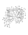
図4は、上記したような什器の使用例を示す斜視図である。図5は、上記したような什器の使用例を示す図であり、図4とは異なる角度から見た斜視図である。
図4,図5に示すように、棚板29上に、プリンタ等の各種の機器80や、その他の物品を載置することができる。また、上部連結部材36,連結フレーム50、オプション部材取付バー40には、ディスプレイモニタ等のオプション部材90が、取付ブラケット95(図3参照)や係止フック、ボルト等を介して係止されている。ここで、上部連結部材36,オプション部材取付バー40は、図3に示した連結フレーム50と同じ断面形状を有しており、什器10の外方を向く側、内方を向く側のいずれの側面にも、オプション部材90を係止させることができる。
また、棚板29上に載置される機器80や、上部連結部材36,連結フレーム50、オプション部材取付バー40に係止されるオプション部材90は、その電源供給、通信等のために用いる配線を、支柱21,31、上部連結部材26,36、連結フレーム50の配線収容空間E1,E2,E3を通して配索することができる。
FIG. 4 is a perspective view showing an example of use of the fixture as described above. FIG. 5 is a view showing an example of use of the fixture as described above, and is a perspective view seen from an angle different from FIG.
As shown in FIGS. 4 and 5,
In addition, the
また、このような什器10は、床面上で移動自在なカート装置100を組み合わせて用いることができるようになっている。
カート装置100は、床面上で走行移動自在なキャスター101を備えた脚部102と、脚部102から上方に向けて延びる支柱103と、支柱103上に支持された天板部104と、を備えている。支柱103は、上下方向に伸縮可能とされ、これによって天板部104の高さが調整可能となっている。
支柱103は、天板部104の下面の平面視中央部に配置されている。これによって、天板部104は、その外周部104aが支柱103から外方にオーバーハングして設けられている。
In addition, such a
The
The
このようなカート装置100は、支柱103を伸縮させて、天板部104が什器10の天板11よりも上方に位置するように、支柱103の長さを調整しておくのが好ましい。これにより、カート装置100は、天板部104の一部を、天板11や棚板29の上方に位置させ、脚部102を天板11の下方に形成された空間に挿入した状態で利用することができる。
In such a
上述したような什器10は、作業面11fを形成する天板11と、天板11の一端側11aと他端側11bにそれぞれ設けられた支持フレーム20,30と、天板11の幅方向に延び、支持フレーム20,30どうしを連結する連結フレーム50と、を備え、支持フレーム20,30は、天板11の前後方向に沿って間隔を空けて天板11の両側に配置された二本一対の支柱21,21、31,31と、二本一対の支柱21,21、31,31の上端部21a,21a、31a,31aどうしを連結する上部連結部材26,36と、を備え、天板11は、二本一対の支柱21、31に、上部連結部材26,36よりも下方位置で固定されている。
The
このような什器10によれば、支持フレーム20,30は、二本一対の支柱21,21、31,31の上端部21a,21a、31a,31aどうしが上部連結部材26,36によって連結されることで門型をなし、さらに上部連結部材26,36よりも下方位置で、二本一対の支柱21,21、31,31の間に配置された天板11が両側の支柱21,21、31,31に固定されている。これにより、支持フレーム20,30は、二本一対の支柱21,21、31,31どうしが、上部連結部材26,36と天板11とによって連結され、矩形状、梯子状をなすこととなり、高い強度を確保することができる。
さらに、天板11の一端側11aと他端側11bとに配置された支持フレーム20,30どうしは、連結フレーム50で連結されるのに加え、天板11によっても固定される。したがって、什器10全体が高強度を有したものとなる。
このような什器10では、連結フレーム50や支持フレーム20,30でオプション部材90を支持する場合、支柱21,21、31,31の特定の部位に荷重が集中するのを抑えることができる。したがって、支柱21,21、31,31の断面積を大きくしたり、その基端部を強固に固定することなく、什器10全体で効率良く荷重を支持することができる。その結果、什器10の十分な支持強度を有しつつ、低コスト化を図ることが可能となる。
According to such a
Further, the support frames 20, 30 disposed on the one
In such a
また、什器10は、支持フレーム20,30間で、天板11の作業面11fを大きな面積で確保することができ、様々な作業や多人数での利用が有効に行える。しかも、什器10にカート装置100を組み合わせて用いることで、各種の作業を効率よく行うことができる。そして、カート装置100は、天板部104が天板11上にオーバーハングし、脚部102も天板11の下方の空間に入り込む。したがって、カート装置100を利用する際にはもちろんのこと、カート装置100の不使用時にも、カート装置100が什器10から外方に大きくはみ出すのを防ぎ、執務空間を有効に利用することが可能となる。
Moreover, the
また、連結フレーム50、上部連結部材36が、オプション部材90を取付可能な係止溝38,51を備えるようにした。これにより、高い位置にある連結フレーム50や上部連結部材36に、オプション部材90を取り付けることができ、ディスプレイモニタ等のオプション部材90を遠方から容易に視認することができる。
Further, the
また、支柱21,21は、配線を収容可能な配線収容空間E1を有しているようにした。これにより、什器10で支持する機器類の配線を配線収容空間E1に収容することで、配線が露出して外観が損なわれるのを防ぐことができる。
Further, the
また、支持フレーム20は、二本一対の支柱21,21間に棚板29が装着されるようにした。これにより、各種の機器80等の物品を棚板29上に載置することができ、その荷重を、強固な門型の支持フレーム20を構成する支柱21,21で確実に支持することができる。
In addition, the
(その他の実施形態)
なお、本発明の什器は、図面を参照して説明した上述の各実施形態に限定されるものではなく、その技術的範囲において様々な変形例が考えられる。
例えば、連結フレーム50は、支持フレーム20と支持フレーム30に対し、前後方向の両側にそれぞれ配置され、両端部が支柱21、31に連結されるようにしたが、これに限らない。
例えば、図6に示すように、連結フレーム50は、例えば1本のみを備え、この連結フレーム50を、支持フレーム20と支持フレーム30の前後方向の中間部において、両端部が上部連結部材26,36に連結するようにしてもよい。
さらに、複数の連結フレーム50を、前後方向に間隔をあけて配置し、それぞれの連結フレーム50の両端部を上部連結部材26,36に連結するようにしても良い。
(Other embodiments)
The fixture of the present invention is not limited to the above-described embodiments described with reference to the drawings, and various modifications are conceivable within the technical scope thereof.
For example, the
For example, as shown in FIG. 6, the
Further, a plurality of connection frames 50 may be arranged at intervals in the front-rear direction, and both ends of each
また、支柱21、31、上部連結部材26、36、連結フレーム50等、什器10を構成する各部材の形状や構成等については、上記に例示した構成に限らず、他の様々な構成としてもよい。
さらに、支持フレーム20と支持フレーム30とが互いに異なる構成としたが、もちろんこれらを同じ構成とすることもできる。
これ以外にも、本発明の主旨を逸脱しない限り、上記実施の形態で挙げた構成を取捨選択したり、他の構成に適宜変更したりすることが可能である。
In addition, the shapes and configurations of the members constituting the
Further, although the
In addition to this, the configuration described in the above embodiment can be selected or changed to another configuration as appropriate without departing from the gist of the present invention.
10 什器
11 天板
11a 一端側
11b 他端側
11f 作業面
20,30 支持フレーム
21,31 支柱
21a,31a 上端部
26,36 上部連結部材
27,37 下部連結部材
40 オプション部材取付バー
50 連結フレーム
38,51 係止溝(オプション部材取付部)
90 オプション部材
100 カート装置
E1,E2 配線収容空間
DESCRIPTION OF
90
Claims (4)
前記天板の一端側と他端側とにそれぞれ設けられた支持フレームと、
前記天板の前記一端側と前記他端側とを結ぶ方向に延び、前記支持フレームの上部どうしを連結する連結フレームと、を備え、
前記支持フレームは、前記天板における前記一端側と前記他端側を結ぶ方向に直交する方向の両側に配置され、床面から上方に向けて延びる二本一対の支柱と、
前記二本一対の前記支柱の上部どうしを連結する上部連結部材と、を備え、
前記天板は、前記二本一対の前記支柱に、前記上部連結部材よりも下方位置で固定されていることを特徴とする什器。 A top plate forming a work surface;
Support frames provided on one end side and the other end side of the top plate,
A connection frame that extends in a direction connecting the one end side and the other end side of the top plate and connects the upper portions of the support frame;
The support frame is disposed on both sides of the top plate in a direction orthogonal to the direction connecting the one end side and the other end side, and a pair of two columns extending upward from the floor surface;
An upper connecting member that connects upper portions of the two pairs of struts,
The furniture is characterized in that the top plate is fixed to the two pairs of columns at a position below the upper connecting member.
Priority Applications (1)
| Application Number | Priority Date | Filing Date | Title |
|---|---|---|---|
| JP2014142563A JP2016016239A (en) | 2014-07-10 | 2014-07-10 | furniture |
Applications Claiming Priority (1)
| Application Number | Priority Date | Filing Date | Title |
|---|---|---|---|
| JP2014142563A JP2016016239A (en) | 2014-07-10 | 2014-07-10 | furniture |
Publications (1)
| Publication Number | Publication Date |
|---|---|
| JP2016016239A true JP2016016239A (en) | 2016-02-01 |
Family
ID=55231950
Family Applications (1)
| Application Number | Title | Priority Date | Filing Date |
|---|---|---|---|
| JP2014142563A Pending JP2016016239A (en) | 2014-07-10 | 2014-07-10 | furniture |
Country Status (1)
| Country | Link |
|---|---|
| JP (1) | JP2016016239A (en) |
Citations (6)
| Publication number | Priority date | Publication date | Assignee | Title |
|---|---|---|---|---|
| JPS6485607A (en) * | 1987-02-16 | 1989-03-30 | Shiyutetsutoraa Marukuumikaeru | Module system for assembling furniture, movable shelf, frame, etc. |
| US6101954A (en) * | 1998-12-17 | 2000-08-15 | Rosemount Office Systems, Inc. | Worktop and frame construction |
| JP2002223873A (en) * | 2001-02-02 | 2002-08-13 | Kokuyo Co Ltd | Structure |
| JP2006055539A (en) * | 2004-08-23 | 2006-03-02 | Itoki Corp | Combination furniture of bed and desk |
| JP2007130095A (en) * | 2005-11-08 | 2007-05-31 | Okamura Corp | Mounting structure for shelf boards, and furniture including the shelf boards and used for nurse station or the like |
| JP2014090909A (en) * | 2012-11-05 | 2014-05-19 | Okamura Corp | Article fitting tool and utensil |
-
2014
- 2014-07-10 JP JP2014142563A patent/JP2016016239A/en active Pending
Patent Citations (6)
| Publication number | Priority date | Publication date | Assignee | Title |
|---|---|---|---|---|
| JPS6485607A (en) * | 1987-02-16 | 1989-03-30 | Shiyutetsutoraa Marukuumikaeru | Module system for assembling furniture, movable shelf, frame, etc. |
| US6101954A (en) * | 1998-12-17 | 2000-08-15 | Rosemount Office Systems, Inc. | Worktop and frame construction |
| JP2002223873A (en) * | 2001-02-02 | 2002-08-13 | Kokuyo Co Ltd | Structure |
| JP2006055539A (en) * | 2004-08-23 | 2006-03-02 | Itoki Corp | Combination furniture of bed and desk |
| JP2007130095A (en) * | 2005-11-08 | 2007-05-31 | Okamura Corp | Mounting structure for shelf boards, and furniture including the shelf boards and used for nurse station or the like |
| JP2014090909A (en) * | 2012-11-05 | 2014-05-19 | Okamura Corp | Article fitting tool and utensil |
Similar Documents
| Publication | Publication Date | Title |
|---|---|---|
| US10390611B2 (en) | Privacy screen table connection mechanism | |
| US20200323341A1 (en) | Modular structure for shelving | |
| JP2016016239A (en) | furniture | |
| JP5231273B2 (en) | Shelf equipment | |
| JP2016016240A (en) | furniture | |
| JP7027772B2 (en) | Top plate support device | |
| JP2011177586A (en) | Fitting device of desktop panel | |
| KR200486886Y1 (en) | No instrument fast assembly accomodates cabinet | |
| JP2010022621A (en) | Desk device with upper shelf | |
| JP2017124102A (en) | Store fixture system | |
| KR20160003475U (en) | Shelves apparatus having anti-bending function | |
| US20200155388A1 (en) | Assistance chair assembly | |
| JP6680557B2 (en) | Furniture system | |
| JP2013183795A (en) | Rack unit, and desk apparatus equipped with the same and desk body | |
| JP5378741B2 (en) | Support structure for optional components in commodity display fixtures | |
| JP2006296607A (en) | Furniture with top board | |
| ES2383764T3 (en) | Modular console for computer equipment and the like | |
| KR200357294Y1 (en) | A multipurpose table | |
| JP6706921B2 (en) | Furniture | |
| KR20190045997A (en) | Shelf assembly | |
| JP5148193B2 (en) | Desk with shelf | |
| JP6985105B2 (en) | furniture | |
| KR101789286B1 (en) | Shelf using tension of wire | |
| JP2006055539A (en) | Combination furniture of bed and desk | |
| KR20230036726A (en) | Anti-fall structure of system furniture |
Legal Events
| Date | Code | Title | Description |
|---|---|---|---|
| A621 | Written request for application examination |
Free format text: JAPANESE INTERMEDIATE CODE: A621 Effective date: 20170630 |
|
| A977 | Report on retrieval |
Free format text: JAPANESE INTERMEDIATE CODE: A971007 Effective date: 20180330 |
|
| A131 | Notification of reasons for refusal |
Free format text: JAPANESE INTERMEDIATE CODE: A131 Effective date: 20180424 |
|
| A521 | Request for written amendment filed |
Free format text: JAPANESE INTERMEDIATE CODE: A523 Effective date: 20180625 |
|
| RD03 | Notification of appointment of power of attorney |
Free format text: JAPANESE INTERMEDIATE CODE: A7423 Effective date: 20181012 |
|
| A131 | Notification of reasons for refusal |
Free format text: JAPANESE INTERMEDIATE CODE: A131 Effective date: 20181023 |
|
| A521 | Request for written amendment filed |
Free format text: JAPANESE INTERMEDIATE CODE: A523 Effective date: 20181213 |
|
| A131 | Notification of reasons for refusal |
Free format text: JAPANESE INTERMEDIATE CODE: A131 Effective date: 20190507 |
|
| A02 | Decision of refusal |
Free format text: JAPANESE INTERMEDIATE CODE: A02 Effective date: 20191105 |