JP2006204679A - Top board supporting structure - Google Patents
Top board supporting structure Download PDFInfo
- Publication number
- JP2006204679A JP2006204679A JP2005022880A JP2005022880A JP2006204679A JP 2006204679 A JP2006204679 A JP 2006204679A JP 2005022880 A JP2005022880 A JP 2005022880A JP 2005022880 A JP2005022880 A JP 2005022880A JP 2006204679 A JP2006204679 A JP 2006204679A
- Authority
- JP
- Japan
- Prior art keywords
- leg plate
- top plate
- bracket
- leg
- engagement
- Prior art date
- Legal status (The legal status is an assumption and is not a legal conclusion. Google has not performed a legal analysis and makes no representation as to the accuracy of the status listed.)
- Granted
Links
Images


Abstract
Description
本発明は、ローパーティションなどの間仕切用パネルの前面に、机、作業台または棚板等として使用しうる天板を、ほぼ水平に保持するようにした天板支持構造に関する。 The present invention relates to a top plate support structure in which a top plate that can be used as a desk, work table, shelf, or the like is held substantially horizontally on the front surface of a partition panel such as a low partition.
従来のこの種の天板支持構造としては、間仕切用パネルを支持する支柱の前面に、複数の係止スリットを上下方向に並べて設け、天板を支持する前後方向を向く脚本体の後端に固定した取付金具における後方を向くフック部分を、上記係止スリットに係止させるようにしたものがある(例えば特許文献1参照)。 In this type of conventional top plate support structure, a plurality of locking slits are arranged in the vertical direction on the front surface of the support column that supports the partition panel, and at the rear end of the leg body that supports the top plate in the front-rear direction. There is one in which a hook portion facing rearward in a fixed mounting bracket is locked by the locking slit (see, for example, Patent Document 1).
また、パーティションの一側面にほぼ水平の横向き凹溝を設け、机等の家具の側面に設けた結合部材の爪部を上記凹溝に係合させることにより、机等の家具をパーティションの一側面に連結するようにしたものもある(例えば特許文献2参照)。
しかし、特許文献1および2に記載されているものは、いずれも天板の高さを変更することができず、しかも特許文献1に記載されているものでは、支柱が存在ところでないと脚本体を間仕切用パネルに連結することができず、天板を間仕切用パネルの表面に沿う任意の位置に装着することができないという問題がある。
また、特許文献2に記載されているものは、机等の家具をパーティションに連結する結合部材を、天板の下面やパーティションの底面等にねじ止めしなければならず、その作業が面倒である。
However, none of the ones described in
In addition, what is described in
本発明は、従来の技術が有する上記のような問題点に鑑み、パネルの前面に沿う左右方向の任意の位置に脚板を取り付けることができるとともに、天板の高さを容易に変更することができ、しかも取付作業が簡単で、天板を安定して確実に支持しうるようにした天板支持構造を提供することを目的としている。 In the present invention, in view of the above-described problems of the prior art, a leg plate can be attached to an arbitrary position in the left-right direction along the front surface of the panel, and the height of the top plate can be easily changed. An object of the present invention is to provide a top plate support structure that is easy to mount and can support the top plate stably and reliably.
本発明によると、上記課題は次のようにして解決される。
(1) 床面に立設した左右方向を向くパネルの前面に、左右方向を向く上下1対の係合溝を設け、前後方向を向く脚板の後端部に設けた上下1対の結合手段を、前記両係合溝に係合して、前記脚板を、前記パネルの前面に左右方向に取付位置調節可能として結合し、かつ前記脚板に複数の係合孔を、上下方向に間隔をおいて設け、天板を支持するブラケットの端部に設けた係止片を、前記係合孔に選択的に係止させることにより、天板を高さ変更可能として、前記パネルに装着する。
According to the present invention, the above problem is solved as follows.
(1) A pair of upper and lower engagement grooves provided in the rear end of the leg plate facing in the front-rear direction is provided on the front surface of the panel standing on the floor facing in the left-right direction. Are engaged with both the engaging grooves, and the leg plate is coupled to the front surface of the panel so that the mounting position can be adjusted in the left-right direction, and a plurality of engagement holes are provided in the leg plate at intervals in the vertical direction. The top plate is mounted on the panel so that the height of the top plate can be changed by selectively locking the engagement pieces provided at the end portions of the brackets supporting the top plate to the engagement holes.
(2) 上記(1)項において、各係合溝の断面形状を、開口部より奥部が広いあり溝状とし、各結合手段を、前記係合溝の奥部に左右方向に摺動可能として嵌合した締付体と、脚板の後部側面に結合した連結材と、前記係合溝の開口部を通って、前記締付体と連結材とを締着する締着手段とを備えるものとする。 (2) In the above item (1), the cross-sectional shape of each engagement groove is a dovetail shape wider than the opening, and each coupling means can be slid in the left-right direction behind the engagement groove. A fastening body fitted as a connecting member, a connecting member coupled to the rear side surface of the leg plate, and fastening means for fastening the fastening member and the connecting member through the opening of the engaging groove. And
(3) 上記(1)または(2)項において、脚板の前部下端を、高さ調節用のアジャスタを介して接床させる。 (3) In the above item (1) or (2), the lower end of the front part of the leg plate is brought into contact with the floor via an adjuster for height adjustment.
(4) 上記(1)〜(3)項のいずれかにおいて、ブラケットを脚板と平行に前後方向に向けて設け、係止片から前後方向に離間したブラケットの一部を、脚板にねじ止めする。 (4) In any one of the above items (1) to (3), the bracket is provided in the front-rear direction in parallel with the leg plate, and a part of the bracket spaced in the front-rear direction from the locking piece is screwed to the leg plate. .
(5) 上記(1)〜(4)項のいずれかにおいて、脚板の一側面後部に角筒部を設け、この角筒部の前面に複数の係合孔を、上下方向に並べて設け、前後方向を向くブラケットの後端に設けた係止片を前記係合孔に選択的に係止しうるようにする。 (5) In any one of the above items (1) to (4), a square tube portion is provided at one side rear portion of the leg plate, and a plurality of engagement holes are provided in the vertical direction on the front surface of the square tube portion. A locking piece provided at the rear end of the bracket facing in a direction can be selectively locked in the engagement hole.
(6) 上記(1)〜(5)項のいずれかにおいて、脚板の一側面にカバーを着脱自在に装着し、このカバーと脚板との間に、ブラケットの一部を挟ませるようにする。 (6) In any one of the above items (1) to (5), a cover is detachably attached to one side of the leg plate, and a part of the bracket is sandwiched between the cover and the leg plate.
本発明によると、次のような効果を奏することができる。
(1) 請求項1記載の発明によると、結合手段を緩めて、係合溝に沿って移動させることにより、パネルに対する脚板の取付位置を左右方向に自由に変更することができるとともに、脚板に設けた複数の係合孔に対するブラケットの係止片の係合箇所を変更するだけで、天板の高さを簡単に段階的に変更することができ、利便性が大である。
According to the present invention, the following effects can be achieved.
(1) According to the invention described in
(2) 請求項2記載の発明によると、結合手段の構成を簡素化することができるとともに、パネルと脚板との結合作業を、天板を外した状態で、パネルの前面側から容易に行うことができ、作業性がよい。
(2) According to the invention described in
(3) 請求項3記載の発明によると、脚板の前部下端を、高さ調節用のアジャスタを介して接床させたので、床面の凹凸をアジャスタにより吸収して、天板を、脚板を介して、床面上に安定して確実に支持させることができる。
(3) According to the invention described in
(4) 請求項4記載の発明によると、ブラケットを脚板と平行に前後方向に向けて設け、係止片から前後方向に離間したブラケットの一部を、脚板にねじ止めしたので、ブラケットが脚板と一体化し、体裁がよく、しかもブラケットのがたつきや、係止片の係合孔からの脱落等を確実に防止することができる。
(4) According to the invention described in
(5) 請求項5記載の発明によると、角筒部が脚板の後部の補強になるだけでなく、複数の係合孔を、外部から目立たなくして脚板に設けることができるとともに、脚板およびブラケットを薄型化することができる。
(5) According to the invention described in
(6) 請求項6記載の発明によると、カバーと脚板との間にブラケットの一部を挟むことにより、外観をよくすることができる。
(6) According to the invention described in
本発明の一実施形態を、添付図面を参照して説明する。
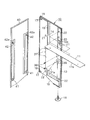
図1は、本発明の一実施形態を用いて、間仕切パネルの前面に机を装着した状態を示す斜視図、図2以下は、その各部の詳細を示す図である。
図1に示すように、この例では、左右方向(図1の右上方を右方、左下方を左方、かつ右下方を前方とする)を向く間仕切パネル(パネル)(1)の前面に、軽作業用の机(2)を装着してある。
An embodiment of the present invention will be described with reference to the accompanying drawings.
FIG. 1 is a perspective view showing a state in which a desk is mounted on the front surface of a partition panel using one embodiment of the present invention, and FIG. 2 and the following figures show details of each part.
As shown in FIG. 1, in this example, on the front of the partition panel (panel) (1) facing the left-right direction (the upper right in FIG. 1 is the right, the lower left is the left, and the lower right is the front). The desk (2) for light work is installed.
間仕切パネル(1)は、下端両側部に高さ調節用のアジャスタ(3)が装着された方形枠状のフレーム(4)の上部、中間部、及び下部の前後面に、断面がほぼ外向きコ字状をなす左右方向を向くガイドレール(5)を固着し、かつフレーム(4)の前後両面における上下に隣接するガイドレール(5)(5)間に、単位パネル(6)(7)を着脱自在に装着して形成されている。この例では、上部の単位パネル(6)を、側面視L字状の多数のハンギングバー(6a)を上下多段状に設けたハンギングパネルとし、下部の単位パネル(7)を、凹凸のないフラットパネルとしてある。 The partition panel (1) has a substantially outward cross-section on the front, back, and front of the square frame-shaped frame (4) with height adjusters (3) mounted on both sides at the bottom. A unit-shaped panel (6) (7) is fixed between the guide rails (5) and (5) adjacent to the top and bottom of the frame (4). Is detachably mounted. In this example, the upper unit panel (6) is a hanging panel in which a large number of hanging bars (6a) having an L-shape in side view are provided in upper and lower stages, and the lower unit panel (7) is a flat surface without unevenness. As a panel.
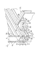
図4及び図5に示すように、各ガイドレール(5)には、開口部(8a)の上下の対向縁に互いに対向する上下1対の対向突片(9)(9)を設けることにより、開口部(8a)よりも奥部(8b)が広い断面あり溝状の左右方向を向く係合溝(8)が形成されている。
上方の対向突片(9)の背面は、内下方を向く傾斜面(9a)をなしており、下方の対向突片(9)の背面は、垂直面(9b)をなしている。
因みに、図4及び図5に示すように、中間部の前後1対のガイドレール(5)(5)は、方形枠状のフレーム(4)の中間部分に設けた左右方向を向く横連結杆(4a)の前後両面に一体的に形成されている。
As shown in FIGS. 4 and 5, each guide rail (5) is provided with a pair of upper and lower opposed projecting pieces (9) and (9) facing each other at the upper and lower opposed edges of the opening (8a). An engagement groove (8) that has a cross section with a wider back part (8b) than the opening (8a) and has a groove shape and faces in the left-right direction is formed.
The back surface of the upper facing protruding piece (9) forms an inclined surface (9a) facing inward and downward, and the back surface of the lower facing protruding piece (9) forms a vertical surface (9b).
Incidentally, as shown in FIGS. 4 and 5, a pair of front and rear guide rails (5) and (5) in the middle part are laterally connected rods provided in the middle part of the rectangular frame-shaped frame (4). It is integrally formed on both front and rear surfaces of (4a).
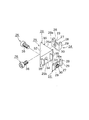
図1〜図3に示すように、机(2)は、後端部が間仕切パネル(1)の前面に左右方向に取付位置調節可能として取り付けられた前後方向を向く左右1対の脚板(10)(10)と、各脚板(10)の内面に高さ変更可能として装着され、一部が脚板(10)より上方に突出するようにした左右1対のブラケット(11)(11)と、両ブラケット(11)(11)により両側部が支持されたほぼ水平の天板(12)とからなっている。 As shown in FIGS. 1 to 3, the desk (2) has a pair of left and right leg plates (10) with the rear end portion attached to the front surface of the partition panel (1) so that the mounting position can be adjusted in the left-right direction. ) (10) and a pair of left and right brackets (11) (11) mounted on the inner surface of each leg plate (10) so that the height can be changed, and partly projecting upward from the leg plate (10), It consists of a substantially horizontal top plate (12) supported on both sides by both brackets (11) (11).
各脚板(10)は、外側面がフラットな垂直板状をなし、内側面の前後部には、上下方向を向く補強用の中空の角筒部(13)(14)が設けられている。前方の角筒部(13)の上部内面には、ほぼブラケット(11)の板厚分だけ凹入させた凹入段部(13a)が形成されている。 Each leg plate (10) has a vertical plate shape with a flat outer surface, and is provided with hollow rectangular tube portions (13) and (14) for reinforcement in the vertical direction on the front and rear portions of the inner surface. On the upper inner surface of the front rectangular tube portion (13), a recessed step portion (13a) is formed that is recessed substantially by the thickness of the bracket (11).
各脚板(10)の下端部内面には、前後方向を向く補強用の中空の角筒部(15)が設けられており、その前端部下面に設けた高さ調節用のアジャスタ(16)を介して、各脚板(10)の前部下端は接床されている。 On the inner surface of the lower end of each leg plate (10), there is provided a hollow rectangular tube portion (15) for reinforcement that faces in the front-rear direction, and an adjuster (16) for height adjustment provided on the lower surface of the front end portion. Accordingly, the front lower end of each leg plate (10) is in contact with the floor.
各脚板(10)における後方の角筒部(14)の内面上下部には、上下方向を向く前後1対のスリット(17)(17)とそれらの間に位置する円形の逃がし孔(18)とがそれぞれ設けられている。
また、角筒部(14)の上部前面における内側のコーナー部には、複数の係合孔(19)が、上下方向に等間隔をもって設けられている。
A pair of front and rear slits (17) and (17) facing in the vertical direction and a circular relief hole (18) positioned between them are formed in the upper and lower portions of the inner surface of the rear square tube portion (14) in each leg plate (10). And are provided respectively.
In addition, a plurality of engagement holes (19) are provided at equal intervals in the vertical direction at the inner corner portion of the upper front surface of the rectangular tube portion (14).
前方の角筒部(13)の凹入段部(13a)の内面には、上下1対のねじ孔(20)(20)が設けられている。
また、各脚板(10)における前後の角筒部(13)(14)の内面には、それぞれ上下1対の係合孔(21)(22)が設けられている。
A pair of upper and lower screw holes (20) and (20) are provided on the inner surface of the recessed step (13a) of the front rectangular tube (13).
Further, a pair of upper and lower engagement holes (21), (22) are provided on the inner surfaces of the front and rear square tube portions (13), (14) of each leg plate (10).
次に、図4〜図8を参照して、各脚板(10)の間仕切パネル(1)への取付構造について説明する。
各脚板(10)は、上下1対の結合手段(23)(下方のものは図示略)を、間仕切パネル(1)の前面における中間部と下部とのガイドレール(5)の係合溝(8)に係合させ、この結合手段(23)を係合溝(8)に沿って摺動させることにより、左右方向の取付位置を調節しうるようにして間仕切パネル(1)の前面に結合されている。
Next, with reference to FIGS. 4-8, the attachment structure to the partition panel (1) of each leg plate (10) is demonstrated.
Each leg plate (10) has a pair of upper and lower coupling means (23) (the lower one is not shown) and an engagement groove (5) in the guide rail (5) between the middle part and the lower part on the front surface of the partition panel (1). 8) is engaged, and the coupling means (23) is slid along the engagement groove (8) so that the mounting position in the left-right direction can be adjusted and coupled to the front surface of the partition panel (1). Has been.
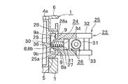
この例では、各結合手段(23)は、ガイドレール(5)の係合溝(8)に嵌合するようにした締付体(24)と、脚板(10)の後部の上下部に設けた前後1対のスリット(17)(17)と逃がし孔(18)とに係合するようにした上記のものと同一の締付体(24)と、各締付体(24)と対向する結合面(25a)(25b)が互いに直角に交わるようにした平面視直角二等辺三角形をなす連結材(25)と、この連結材(25)と各締付体(24)とを締着する1対の締着手段(26)とを備えている。 In this example, each coupling means (23) is provided at the upper and lower parts of the rear part of the fastening body (24) and the leg plate (10) so as to be fitted in the engaging groove (8) of the guide rail (5). The same tightening body (24) as described above, which is engaged with the pair of front and rear slits (17), (17) and the relief hole (18), and faces each of the tightening bodies (24). The connecting material (25) forming an isosceles right triangle in plan view in which the coupling surfaces (25a) and (25b) cross each other at right angles, and the connecting material (25) and each fastening body (24) are fastened. A pair of fastening means (26).
各締付体(24)は、連結材(25)の結合面(25a)(25b)と平行をなす垂直の基片(27)と、この基片(27)の両側部より連結材(25)から離れる方向を向き、かつ先端部に、上方に延出して、係合溝(8)における上方の対向突片(9)の背面や、脚板(10)の後部におけるスリット(17)の上縁の背面等に係合しうる係合部(28)が設けられた1対の側片(29)(29)とを備えている。
各係合部(28)の前縁には、係合溝(8)における上方の対向突片(9)の背面に形成された傾斜面(9a)と同方向に傾斜する傾斜面(28a)が形成されている。
また、基片(27)の中央には、ねじ孔(30)が設けられている。
Each fastening body (24) includes a vertical base piece (27) parallel to the coupling surfaces (25a) and (25b) of the connecting material (25), and a connecting material (25 from both sides of the base piece (27). ) And extending upward to the tip, and above the rear surface of the upper opposing protruding piece (9) in the engagement groove (8) and the slit (17) at the rear of the leg plate (10). And a pair of side pieces (29) and (29) provided with engaging portions (28) that can be engaged with the rear surface of the edge.
An inclined surface (28a) inclined in the same direction as the inclined surface (9a) formed on the back surface of the upper opposing protruding piece (9) in the engaging groove (8) is provided at the front edge of each engaging portion (28). Is formed.
A screw hole (30) is provided in the center of the base piece (27).
連結材(25)は、各結合面(25a)(25b)を形成する互いに直交する2枚の板状の垂直壁部(31)(31)と、それらより長い2辺を二等辺とする直角二等辺三角形をなして、垂直壁部(31)(31)の上下部を覆う上下カバー部(32)(33)とを備えている。 The connecting material (25) is composed of two perpendicular plate-like vertical wall portions (31) and (31) forming the respective coupling surfaces (25a) and (25b), and a right angle having two longer sides as isosceles sides. Upper and lower cover portions (32), (33) are provided that form isosceles triangles and cover the upper and lower portions of the vertical wall portions (31), (31).
各垂直壁部(31)の中央には、通孔(34)が穿設されている。
また、各垂直壁部(31)の外側面である結合面(25a)(25b)には、各間仕切パネル(1)の係合溝(8)や脚板(10)のスリット(17)等に嵌合することにより、各間仕切パネル(1)や脚板(10)に対する連結材(25)の上下方向の移動を阻止する左右1対の側面視横向台形状の突片(35)(35)が突設されている。
これらの突片(35)(35)の対向面は、平面視において各結合面(25a)(25b)から離れる方向に向かってわずかに拡開するように傾斜しており、締着手段(26)により各締付体(24)を締め付ける際に、各締付体(24)が両突片(35)(35)間に嵌合することにより、各締付体(24)は、姿勢が乱れたり、回転したすることなく、円滑に案内される。
したがって、締着手段(26)により、各締付体(24)を、安定して、迅速に締め付けることができる。
A through hole (34) is formed in the center of each vertical wall (31).
In addition, the coupling surfaces (25a) and (25b), which are the outer surfaces of the vertical wall portions (31), are formed in the engagement grooves (8) of the partition panels (1) and the slits (17) of the leg plates (10). When fitted, there are a pair of left and right side trapezoidal protrusions (35) and (35) that prevent the connecting member (25) from moving vertically with respect to each partition panel (1) and leg plate (10). Projected.
The opposing surfaces of these projecting pieces (35) and (35) are inclined so as to slightly expand toward the direction away from the respective coupling surfaces (25a) and (25b) in plan view, and fastening means (26 ), When each tightening body (24) is tightened, each tightening body (24) is fitted between both projecting pieces (35) and (35), so that each tightening body (24) has a posture. It is guided smoothly without being disturbed or rotating.
Therefore, each fastening body (24) can be stably and quickly fastened by the fastening means (26).
締着手段(26)は、この例では、連結材(25)における各結合面(25a)(25b)に設けた通孔(34)へ挿入され、かつ各締付体(24)に設けたねじ孔(30)に螺合するようにした締付ねじ(36)としてある。 In this example, the fastening means (26) is inserted into the through holes (34) provided in the coupling surfaces (25a) and (25b) of the connecting member (25), and is provided in each fastening body (24). The tightening screw (36) is adapted to be screwed into the screw hole (30).
したがって、この実施形態においては、一方の締付体(24)を間仕切パネル(1)の係合溝(8)に嵌合して、その係合部(28)を対向突片(9)の背面に係合させするとともに、連結材(25)の結合面(25a)における両突片(35)(35)を係合溝(8)に嵌合して、結合面(25a)を間仕切パネル(1)のガイドレール(5)の表面に当接させ、また、他方の締付体(24)の両側片(29)(29)と連結材(25)の結合面(25b)における両突片(35)(35)とを、脚板(10)の後部のスリット(17)(17)にそれぞれ嵌合し、かつ各垂直壁部(31)の通孔(34)へ挿入した締付ねじ(36)を、各締付体(24)のねじ孔(30)に螺合して、締め付けることにより、一方の締付体(24)と連結材(25)の結合面(25a)との間で、間仕切パネル(1)の係合溝(8)における上方の対向突片(9)を挟んで、間仕切パネル(1)に連結材(25)を強固に連結することができるとともに、他方の締付体(24)と連結材(25)の結合面(25b)との間で、脚板(10)の後部におけるスリット(17)(17)の上方の板厚部分を挟んで、連結材(25)に脚板(10)を強固に連結することができる。
なお、脚板(10)側に係合される締付体(24)における基片(27)の背面側に突出する締付ねじ(36)の先端部は、脚板(10)における両スリット(17)(17)間に配設された逃がし孔(18)内に進入するので、脚板(10)の内面と干渉することはない。
Therefore, in this embodiment, one tightening body (24) is fitted into the engaging groove (8) of the partition panel (1), and the engaging portion (28) is connected to the opposing protruding piece (9). While engaging with the back surface, both projecting pieces (35) and (35) on the coupling surface (25a) of the connecting member (25) are fitted into the engagement groove (8), and the coupling surface (25a) is partitioned into the partition panel. (1) The guide rail (5) is brought into contact with the surface of the other clamp body (24), and the both ends (29) and (29) of the other fastening body (24) and the joints (25b) on the coupling surface (25b) Tightening screws that insert the pieces (35) and (35) into the slits (17) and (17) at the rear of the leg plate (10) and insert them into the through holes (34) of each vertical wall (31) (36) are screwed into the screw holes (30) of the respective tightening bodies (24) and tightened so that one tightening body (24) and the coupling surface (25a) of the connecting member (25) The connecting material (25) can be firmly connected to the partition panel (1) by sandwiching the upper facing protruding piece (9) in the engagement groove (8) of the partition panel (1). In addition, the plate thickness portion above the slits (17) and (17) in the rear part of the leg plate (10) is sandwiched between the other fastening body (24) and the coupling surface (25b) of the connecting member (25). The leg plate (10) can be firmly connected to the connecting member (25).
Note that the tip of the fastening screw (36) protruding to the back side of the base piece (27) in the fastening body (24) engaged with the leg plate (10) side is provided with both slits (17 ) And (17) enter the escape hole (18) disposed between them, so that they do not interfere with the inner surface of the leg plate (10).
また、締付体(24)の係合部(28)に傾斜面(28a)を設けて、これを係合溝(8)における対向突片(9)の傾斜面(9a)に係合させて締め付けるようにしたので、締付体(24)とガイドレール(5)とを、離脱しにくいように強く噛み合わせることができる。 In addition, an inclined surface (28a) is provided in the engaging portion (28) of the tightening body (24), and this is engaged with the inclined surface (9a) of the opposing projecting piece (9) in the engaging groove (8). Thus, the tightening body (24) and the guide rail (5) can be strongly engaged with each other so as not to easily come off.
なお、上記実施形態においては、連結材(25)における両結合面(25a)(25b)のなす角度を90°としてあるが、この角度を変更することにより、間仕切パネル(1)と脚板(10)とのなす角度を、90°以外の任意の角度とすることができる。 In the above embodiment, the angle formed by the two coupling surfaces (25a) and (25b) in the connecting member (25) is 90 °. By changing this angle, the partition panel (1) and the leg plate (10 ) Can be any angle other than 90 °.
また、締付体(24)の係合部(28)を、下向きとして、係合溝(8)における下方の対向突片(9)の背面に係合させたり、または係合部(28)を締付体(24)の上下部に設けて、それらを係合溝(8)における上下の対向突片(9)(9)の背面にそれぞれ係合させるようにしてもよい。 Further, the engaging portion (28) of the tightening body (24) is directed downward to be engaged with the back surface of the lower facing protruding piece (9) in the engaging groove (8), or the engaging portion (28). May be provided on the upper and lower portions of the tightening body (24) and engaged with the back surfaces of the upper and lower opposed protruding pieces (9) and (9) in the engaging groove (8), respectively.
ブラケット(11)は、後端に下向き鉤形の複数の係止片(37)を備える前後方向を向く垂直の基片(11a)の上端に、天板(12)を支持するほぼ水平の天板支持片(11b)を内方に向けて折曲形成したものよりなり、後端の複数の係止片(37)を、脚板(10)における後方の角筒部(14)の上部前面に設けられた複数の係合孔(19)に選択的に係止させることにより、上下位置調節可能として脚板(10)に装着されている。 The bracket (11) has a substantially horizontal ceiling that supports the top plate (12) on the upper end of a vertical base piece (11a) that faces in the front-rear direction and has a plurality of hook-shaped locking pieces (37) that are downwardly hooked at the rear end. It consists of a plate support piece (11b) bent inward, and a plurality of locking pieces (37) at the rear end are attached to the upper front surface of the square tube portion (14) at the rear of the leg plate (10). It is attached to the leg plate (10) so that the vertical position can be adjusted by selectively engaging with the plurality of engagement holes (19) provided.
ブラケット(11)の基片(11a)は、脚板(10)より上方に突出するとともに、脚板(10)における前方の角筒部(13)の凹入段部(13a)を通って脚板(10)より前方に突出している。その凹入段部(13a)を通過する個所において、ブラケット(11)の基片(11a)は、ねじ孔(20)(20)に螺合する固定ねじ(38)(38)をもって、脚板(10)の内面に螺着されている。 The base piece (11a) of the bracket (11) protrudes upward from the leg plate (10) and passes through the recessed step (13a) of the front rectangular tube (13) in the leg plate (10). ) Protrudes further forward. The base piece (11a) of the bracket (11) has a fixing screw (38) (38) that is screwed into the screw hole (20) (20) at a portion passing through the recessed step (13a), and a leg plate ( It is screwed on the inner surface of 10).
ブラケット(11)の上下位置を変更した際にも、ブラケット(11)を固定ねじ(38)(38)をもって脚板(10)の内面に螺着しうるようにするため、基片(11a)の前後方向の中間部には、ブラケット(11)の上下位置を変更した際にいずれかのものがねじ孔(20)(20)と整合するように、多数の取付孔(39)が設けられている。 Even when the vertical position of the bracket (11) is changed, the bracket (11) can be screwed onto the inner surface of the leg plate (10) with the fixing screws (38) (38). A number of mounting holes (39) are provided in the middle part in the front-rear direction so that when the vertical position of the bracket (11) is changed, one of them aligns with the screw holes (20) (20). Yes.
図2は、ブラケット(11)を低位置で脚板(10)に装着したときの状態を、図9は、ブラケット(11)を高位置で脚板(10)に装着したときの状態をそれぞれ示す。
なお、この例では、図示および説明を簡略化するため、ブラケット(11)を上下2段階に位置変更可能としてあるが、係合孔(19)と取付孔(39)の数を増やすことにより、上下3段階以上に位置変更できるようにすることができる。
2 shows a state when the bracket (11) is attached to the leg plate (10) at a low position, and FIG. 9 shows a state when the bracket (11) is attached to the leg plate (10) at a high position.
In this example, in order to simplify the illustration and description, the position of the bracket (11) can be changed in two stages, upper and lower, but by increasing the number of engagement holes (19) and attachment holes (39), The position can be changed in three or more stages.
図3に示すように、脚板(10)の内面における連結材(25)の取付部分がある後部を除くほぼ全面は、方形のカバー(40)により覆われている。
このカバー(40)は、その下部に設けた前後1対の下向きのフック(41)(41)を、脚板(10)の内面における下部の係合孔(22)(22)に係止し、かつカバー(40)の上部に設けた前後1対の弾性変形可能な側面視ほぼ菱形の頭部(42a)を有するクリップ(42)(42)を、脚板(10)の内面における上部の係合孔(21)(21)に圧嵌することにより、脚板(10)の内面に着脱自在に装着されている。
ブラケット(11)における基片(11a)の大部分は、このカバー(40)と脚板(10)との間に挟まれ、外部に露呈することはないので、美麗な外観を保つことができる。
As shown in FIG. 3, almost the entire surface of the inner surface of the leg plate (10) except for the rear portion where the connecting member (25) is attached is covered with a rectangular cover (40).
The cover (40) has a pair of front and rear downward hooks (41) (41) provided at the lower part thereof engaged with lower engagement holes (22) (22) on the inner surface of the leg plate (10), The clip (42) (42) having a pair of front and rear elastically deformable side-view substantially rhombic heads (42a) provided on the upper part of the cover (40) is engaged with the upper part on the inner surface of the leg plate (10). By press-fitting into the holes (21) and (21), the inner surface of the leg plate (10) is detachably mounted.
Since most of the base piece (11a) in the bracket (11) is sandwiched between the cover (40) and the leg plate (10) and is not exposed to the outside, a beautiful appearance can be maintained.
天板(12)は、左右1対の脚板(10)とそのカバー(40)との間から上方に突出する左右1対のブラケット(11)における基片(11a)の上端に連設された天板支持片(11b)上に左右の両側部下面が載置され、かつ下方より適宜ねじ止め(図示略)されている。 The top plate (12) is connected to the upper end of the base piece (11a) in the pair of left and right brackets (11) protruding upward from between the pair of left and right leg plates (10) and the cover (40). The lower surfaces of the left and right sides are placed on the top plate support piece (11b), and are appropriately screwed (not shown) from below.
したがって、左右のブラケット(11)を上記のように各脚板(10)に対して高さ変更することにより、天板(12)の高さを複数段階に変更することができる。 Therefore, by changing the height of the left and right brackets (11) with respect to each leg plate (10) as described above, the height of the top plate (12) can be changed in a plurality of stages.
また、締着手段(26)である締付ねじ(36)を緩めて、係合溝(8)に沿って移動させることにより、間仕切パネル(1)に対する脚板(10)の取付位置を左右方向に自由に変更することができ。 Further, by loosening the fastening screw (36) which is the fastening means (26) and moving it along the engaging groove (8), the mounting position of the leg plate (10) with respect to the partition panel (1) is adjusted in the left-right direction. Can be changed freely.
さらに、この実施形態の構成により、「発明の効果」として上述した効果を奏することができる。 Furthermore, with the configuration of this embodiment, the effects described above as “effects of the invention” can be achieved.
以上、本発明の一実施形態について説明したが、本発明の特許請求の範囲を逸脱しない範囲内で、上記実施形態に種々の変形や変更を施すことが可能である。
例えば、結合手段(23)における連結材(25)を、予め脚板(10)の内面に溶接等により固着しておいたり、締付体(24)を、係合溝(8)の奥部(8a)に左右方向に摺動可能として嵌合した板ナットとしたりしてもよい。
As mentioned above, although one Embodiment of this invention was described, it is possible to give a various deformation | transformation and change to the said embodiment within the range which does not deviate from the claim of this invention.
For example, the connecting member (25) in the connecting means (23) is fixed to the inner surface of the leg plate (10) in advance by welding or the like, or the fastening body (24) is attached to the inner portion of the engaging groove (8) ( It may be a plate nut fitted in 8a) so as to be slidable in the left-right direction.
また、図5に示す逃がし孔(18)をねじ孔とし、これに締付ねじ(36)を直接螺合させることにより、連結材(25)を、締付体(24)を介在させることなく、直接脚板(10)に締着してもよい。 Further, the relief hole (18) shown in FIG. 5 is used as a screw hole, and the fastening screw (36) is directly screwed into the screw hole, so that the connecting member (25) can be inserted without interposing the fastening body (24). Alternatively, it may be fastened directly to the leg plate (10).
(1)間仕切パネル(パネル)
(2)机
(3)アジャスタ
(4)フレーム
(4a)横連結杆
(5)ガイドレール
(6)(7)単位パネル
(6a)ハンギングバー
(8)係合溝
(8a)開口部
(8b)奥部
(9)対向突片
(9a)傾斜面
(9b)垂直面
(10)脚板
(11)ブラケット
(11a)基片
(11b)天板支持片
(12)天板
(13)(14)(15)角筒部
(13a)凹入段部
(16)アジャスタ
(17)スリット
(18)逃がし孔
(19)係合孔
(20)ねじ孔
(21)(22)係合孔
(23)結合手段
(24)締付体
(25)連結材
(25a)(25b)結合面
(26)締着手段
(27)基片
(28)係合部
(28a)傾斜面
(29)側片
(30)ねじ孔
(31)垂直壁部
(32)上カバー部
(33)下カバー部
(34)通孔
(35)突片
(36)締付ねじ
(37)係止片
(38)固定ねじ
(39)取付孔
(40)カバー
(41)フック
(42)クリップ
(42a)頭部
(1) Partition panel (panel)
(2) Desk
(3) Adjuster
(4) Frame
(4a) Horizontal connection
(5) Guide rail
(6) (7) Unit panel
(6a) Hanging bar
(8) Engaging groove
(8a) Opening
(8b) Back
(9) Opposing piece
(9a) Inclined surface
(9b) Vertical plane
(10) Leg plate
(11) Bracket
(11a) Base piece
(11b) Top plate support piece
(12) Top plate
(13) (14) (15) Square tube
(13a) Recessed step
(16) Adjuster
(17) Slit
(18) Relief hole
(19) Engagement hole
(20) Screw hole
(21) (22) Engagement hole
(23) Coupling means
(24) Fastening body
(25) Connecting material
(25a) (25b) Bonding surface
(26) Fastening means
(27) Base piece
(28) Engagement part
(28a) Inclined surface
(29) Side piece
(30) Screw hole
(31) Vertical wall
(32) Upper cover
(33) Lower cover
(34) Through hole
(35) Projection
(36) Tightening screw
(37) Locking piece
(38) Fixing screw
(39) Mounting hole
(40) Cover
(41) Hook
(42) Clip
(42a) Head
Claims (6)
The top plate support structure according to any one of claims 1 to 5, wherein a cover is detachably attached to one side surface of the leg plate, and a part of the bracket is sandwiched between the cover and the leg plate.
Priority Applications (1)
| Application Number | Priority Date | Filing Date | Title |
|---|---|---|---|
| JP2005022880A JP4518972B2 (en) | 2005-01-31 | 2005-01-31 | Top plate support structure |
Applications Claiming Priority (1)
| Application Number | Priority Date | Filing Date | Title |
|---|---|---|---|
| JP2005022880A JP4518972B2 (en) | 2005-01-31 | 2005-01-31 | Top plate support structure |
Publications (2)
| Publication Number | Publication Date |
|---|---|
| JP2006204679A true JP2006204679A (en) | 2006-08-10 |
| JP4518972B2 JP4518972B2 (en) | 2010-08-04 |
Family
ID=36962111
Family Applications (1)
| Application Number | Title | Priority Date | Filing Date |
|---|---|---|---|
| JP2005022880A Expired - Fee Related JP4518972B2 (en) | 2005-01-31 | 2005-01-31 | Top plate support structure |
Country Status (1)
| Country | Link |
|---|---|
| JP (1) | JP4518972B2 (en) |
Cited By (2)
| Publication number | Priority date | Publication date | Assignee | Title |
|---|---|---|---|---|
| CN102650464A (en) * | 2011-02-25 | 2012-08-29 | 宜闻斯控制台(昆山)有限公司 | Structurally improved console |
| KR101250630B1 (en) * | 2007-11-09 | 2013-04-03 | 가부시기가이샤 우찌다요우고우 | Desk |
Families Citing this family (3)
| Publication number | Priority date | Publication date | Assignee | Title |
|---|---|---|---|---|
| CN105705710B (en) | 2013-11-01 | 2018-12-04 | 株式会社冈村制作所 | plate body |
| CN106473469A (en) * | 2015-09-02 | 2017-03-08 | 森特士兴集团股份有限公司 | A kind of locker suspending type multi-layer dividing plate |
| CN106037301B (en) * | 2016-06-19 | 2018-06-19 | 邹素芬 | A kind of liftable locker |
Citations (3)
| Publication number | Priority date | Publication date | Assignee | Title |
|---|---|---|---|---|
| JPH0593257U (en) * | 1992-05-26 | 1993-12-21 | 株式会社イトーキクレビオ | Device to prevent the leg brackets from coming off in the partition device |
| JP2001182197A (en) * | 1999-12-27 | 2001-07-03 | Itoki Crebio Corp | Commodity-mounting apparatus for partition apparatus |
| JP2003166302A (en) * | 2001-11-30 | 2003-06-13 | Itoki Co Ltd | Connecting structure for furniture and partition and partition therefor |
-
2005
- 2005-01-31 JP JP2005022880A patent/JP4518972B2/en not_active Expired - Fee Related
Patent Citations (3)
| Publication number | Priority date | Publication date | Assignee | Title |
|---|---|---|---|---|
| JPH0593257U (en) * | 1992-05-26 | 1993-12-21 | 株式会社イトーキクレビオ | Device to prevent the leg brackets from coming off in the partition device |
| JP2001182197A (en) * | 1999-12-27 | 2001-07-03 | Itoki Crebio Corp | Commodity-mounting apparatus for partition apparatus |
| JP2003166302A (en) * | 2001-11-30 | 2003-06-13 | Itoki Co Ltd | Connecting structure for furniture and partition and partition therefor |
Cited By (2)
| Publication number | Priority date | Publication date | Assignee | Title |
|---|---|---|---|---|
| KR101250630B1 (en) * | 2007-11-09 | 2013-04-03 | 가부시기가이샤 우찌다요우고우 | Desk |
| CN102650464A (en) * | 2011-02-25 | 2012-08-29 | 宜闻斯控制台(昆山)有限公司 | Structurally improved console |
Also Published As
| Publication number | Publication date |
|---|---|
| JP4518972B2 (en) | 2010-08-04 |
Similar Documents
| Publication | Publication Date | Title |
|---|---|---|
| JP4518972B2 (en) | Top plate support structure | |
| JP4414743B2 (en) | table | |
| JP2006280810A (en) | Display shelf apparatus | |
| JP2008121382A (en) | Panel supporting structure | |
| JP4551188B2 (en) | Shelf device with tiltable shelf board | |
| JP4782567B2 (en) | Mounting structure of shelf board to partition panel | |
| JP2010125015A (en) | Desk panel and mounting structure for the same | |
| JP2005232869A (en) | Stable leg device of partition panel | |
| JP2007267992A (en) | Structure for attaching panel to top plate elevating and lowering type table | |
| JP2004016401A (en) | Desk with shelf | |
| JP5304014B2 (en) | Desktop panel mounting device | |
| JP3758607B2 (en) | Shelf board mounting device | |
| JP2008104711A (en) | Device for attaching hanging beam between existing posts | |
| JP4163594B2 (en) | Shelf mounting structure for partition panels | |
| JP2007289354A (en) | Recombination desk with shelf | |
| JP5262832B2 (en) | Desk panel mounting structure | |
| JP2009261841A5 (en) | ||
| JP2004016403A (en) | Device for attaching light to shelf board | |
| JP2009261821A (en) | Workstation | |
| JP2011172978A (en) | Leg device for desk | |
| JP6638335B2 (en) | Auxiliary top device | |
| JP4202727B2 (en) | Double-side inclined display shelf | |
| JP2006129994A (en) | Mounting structure of back panel in furniture | |
| JP4831402B2 (en) | Low partition bracket mounting structure and bracket | |
| JP2005264549A (en) | Bracket mounting structure for low partition |
Legal Events
| Date | Code | Title | Description |
|---|---|---|---|
| A621 | Written request for application examination |
Free format text: JAPANESE INTERMEDIATE CODE: A621 Effective date: 20080104 |
|
| A977 | Report on retrieval |
Free format text: JAPANESE INTERMEDIATE CODE: A971007 Effective date: 20100423 |
|
| TRDD | Decision of grant or rejection written | ||
| A01 | Written decision to grant a patent or to grant a registration (utility model) |
Free format text: JAPANESE INTERMEDIATE CODE: A01 Effective date: 20100511 |
|
| A01 | Written decision to grant a patent or to grant a registration (utility model) |
Free format text: JAPANESE INTERMEDIATE CODE: A01 |
|
| A61 | First payment of annual fees (during grant procedure) |
Free format text: JAPANESE INTERMEDIATE CODE: A61 Effective date: 20100518 |
|
| FPAY | Renewal fee payment (event date is renewal date of database) |
Free format text: PAYMENT UNTIL: 20130528 Year of fee payment: 3 |
|
| R150 | Certificate of patent or registration of utility model |
Free format text: JAPANESE INTERMEDIATE CODE: R150 |
|
| FPAY | Renewal fee payment (event date is renewal date of database) |
Free format text: PAYMENT UNTIL: 20140528 Year of fee payment: 4 |
|
| R250 | Receipt of annual fees |
Free format text: JAPANESE INTERMEDIATE CODE: R250 |
|
| R250 | Receipt of annual fees |
Free format text: JAPANESE INTERMEDIATE CODE: R250 |
|
| R250 | Receipt of annual fees |
Free format text: JAPANESE INTERMEDIATE CODE: R250 |
|
| LAPS | Cancellation because of no payment of annual fees |