JP6638335B2 - Auxiliary top device - Google Patents
Auxiliary top device Download PDFInfo
- Publication number
- JP6638335B2 JP6638335B2 JP2015219167A JP2015219167A JP6638335B2 JP 6638335 B2 JP6638335 B2 JP 6638335B2 JP 2015219167 A JP2015219167 A JP 2015219167A JP 2015219167 A JP2015219167 A JP 2015219167A JP 6638335 B2 JP6638335 B2 JP 6638335B2
- Authority
- JP
- Japan
- Prior art keywords
- top plate
- base rod
- rod
- plate
- holding member
- Prior art date
- Legal status (The legal status is an assumption and is not a legal conclusion. Google has not performed a legal analysis and makes no representation as to the accuracy of the status listed.)
- Active
Links
- 230000000630 rising effect Effects 0.000 claims description 17
- 230000003014 reinforcing effect Effects 0.000 description 9
- 230000002787 reinforcement Effects 0.000 description 3
- 229910000831 Steel Inorganic materials 0.000 description 2
- 238000005452 bending Methods 0.000 description 2
- 239000010959 steel Substances 0.000 description 2
- 101000793686 Homo sapiens Azurocidin Proteins 0.000 description 1
- 238000006243 chemical reaction Methods 0.000 description 1
- 238000006073 displacement reaction Methods 0.000 description 1
- JGPMMRGNQUBGND-UHFFFAOYSA-N idebenone Chemical compound COC1=C(OC)C(=O)C(CCCCCCCCCCO)=C(C)C1=O JGPMMRGNQUBGND-UHFFFAOYSA-N 0.000 description 1
- 229960004135 idebenone Drugs 0.000 description 1
- 238000000034 method Methods 0.000 description 1
- 230000001105 regulatory effect Effects 0.000 description 1
- 238000010079 rubber tapping Methods 0.000 description 1
- 229920003002 synthetic resin Polymers 0.000 description 1
- 239000000057 synthetic resin Substances 0.000 description 1
Images


Description
本発明は、補助天板装置に係わり、更に詳しくはデスクやテーブル等の天板に補助天板を取付けて使用する補助天板装置に関するものである。 The present invention relates to an auxiliary top plate device, and more particularly to an auxiliary top plate device used by attaching an auxiliary top plate to a top plate such as a desk or a table.
従来から、デスクやテーブル等の天板の一部縁部に、補助天板を取付けて天板を拡張し、あるいは異形天板を構成して使い勝手を改善する構造の補助天板装置は、既に各種提供されている。 Conventionally, an auxiliary top plate device with a structure that expands the top plate by attaching an auxiliary top plate to a part of the edge of the top plate such as a desk or a table, or configures a modified top plate to improve usability, has already been developed. Various are provided.
例えば、特許文献1には、天板の一側縁に設けた脚板体の前部を可動脚板とし、該可動脚板の上縁を前記天板の一側縁に蝶番で連結して外側へ回動可能とし、該可動脚板を水平状態とするとともに、該可動脚体の下面を支持脚で支持して天板と面一となした使用形態を実現する補助天板機能付き机が開示されている。この場合、可動脚板は天板に常時蝶番で連結したものであるので、可動脚板を補助天板として使用しないときには、脚板体や幕板として利用するなどの特殊な用途がない限り、邪魔になったり、外観性を損なうことになる。
For example, in
それに対して、必要に応じて補助天板あるいは拡張天板を天板の一部に連続させて取付ける構造として、特許文献2,3に記載のものがある。特許文献2には、机の天板の前縁一部に補助天板を取付けるための取付構造において、補助天板の下面に連結金具の前部を取付け、該補助天板の後縁よりも後方へ突出した連結金具の後部であって両側後端部に後向きフックを形成するとともに、それよりも前方の両側に取付孔を有する水平な固定板を形成し、前記後向きフックを天板下面の奥行方向中間部に横設した中補強部材の前面に形成した係止孔に嵌合係止するとともに、前記両固定板を天板下面の前縁に横設した前補強部材の下面に前記取付孔を用いてネジ止めしてなる机の補助天板取付構造が開示されている。更に、特許文献3には、天板の下面に連結杆及び連結板の後部をネジ止めし、該連結杆及び連結板の前記天板より手前に突出した突出部に拡張天板を載置した状態でネジ止めした構造の拡張天板が開示されている。
On the other hand,
特許文献2に記載のものは、天板に連結金具を用いて補助天板を比較的簡単に取付けることができるものの、連結金具の後向きフックと天板の中補強部材の係止孔との間のクリアランスによる若干の上下のガタツキは避けられず、また連結金具の横幅が大きく嵩張るといった課題がある。また、特許文献3に記載のものは、連結杆と連結板が異なる形状であるので、部品管理の手間が増え、また連結杆を天板下面にネジ止めする作業において位置決めが難しく、狭い空間でのネジ止め作業に労力を要するといった課題がある。
In the device described in
そこで、本発明が前述の状況に鑑み、解決しようとするところは、デスクやテーブル等の天板の一部縁部に、該天板の下面に着脱可能に取付けた支持アームを介して支持した補助天板を配置し、天板を拡張して使用することが可能な補助天板装置において、天板の下面に支持アームを、簡単な作業で、確実に且つ支持強度が高く、またガタツキのない状態で取付けることが可能な補助天板装置を提供する点にある。 In view of the above-mentioned situation, the present invention is intended to solve the problem by supporting a part of a top plate such as a desk or a table via a support arm detachably attached to a lower surface of the top plate. In the auxiliary top device that can be used by extending the top with the auxiliary top arranged, the support arm is provided on the lower surface of the top with a simple operation, reliably and with high support strength, An object of the present invention is to provide an auxiliary top plate device that can be mounted without any additional components.
本発明は、前述の課題解決のために、デスクやテーブルの天板の一部縁部に、該天板の下面に着脱可能に取付けた支持アームを介して支持した補助天板を配置し、天板を拡張して使用することが可能な補助天板装置であって、前記天板の下面の前後部にスリット孔を備え、前記支持アームは、前後部の前記スリット孔にそれぞれ係止する前後一方向に向いた固定フック部を設けるとともに、後部又は前部に前後変位可能且つ固定可能に設けた保持部材に前記固定フック部と前後逆方向に向いた可動フック部を設けてなり、後部又は前部のスリット孔に前記固定フック部と可動フック部を共に挿入状態で前後逆方向にスライドさせて該スリット孔に抜け止め係合した状態で前記保持部材を固定してなることを特徴とする補助天板装置を構成した(請求項1)。 In order to solve the above-described problems, the present invention arranges an auxiliary top plate supported on a partial edge of a top plate of a desk or table via a support arm detachably attached to a lower surface of the top plate, An auxiliary top plate device capable of extending and using a top plate, comprising slit holes at front and rear portions of a lower surface of the top plate, wherein the support arms are respectively engaged with the slit holes at front and rear portions. A fixed hook portion facing in one direction is provided, and a movable hook portion facing the fixed hook portion in a direction opposite to the fixed hook portion is provided on a holding member provided at the rear portion or the front portion so as to be displaceable and fixable. Or, the fixed hook portion and the movable hook portion are both inserted into the front slit hole and slid in the front-rear direction while being inserted, and the retaining member is fixed in a state where the retaining member is engaged with the slit hole so as to prevent the hook portion from coming off. Auxiliary top plate device Claim 1).
ここで、前記支持アームは、前記天板の下面に取付けるベース杆と、該ベース杆の後部又は前部に前後変位可能且つ固定可能に設けた保持部材と、該ベース杆に後部を連結して前記天板の縁部から突出した前部に前記補助天板を載置して取付ける支持杆とからなり、前記ベース杆は、前後端部に前後部の前記スリット孔にそれぞれ係止する前後一方向に向いた固定フック部を設けてなることが好ましい(請求項2)。 The support arm includes a base rod attached to the lower surface of the top plate, a holding member provided at the rear or front part of the base rod so as to be capable of being displaced back and forth and fixed, and a rear part connected to the base rod. A supporting rod for mounting and mounting the auxiliary top plate on a front portion protruding from an edge of the top plate, wherein the base rod is fixed at front and rear end portions to front and rear portions respectively engaged with the slit holes of the front and rear portions. It is preferable to provide a fixed hook portion oriented in the direction (claim 2).
この場合、前記天板の下面の前後部に前後方向を向いたスリット孔をそれぞれ平行に二対設け、前記ベース杆は、両垂直板と水平板を有する上方開放の断面略コ字形の長尺部材であり、両垂直板の前後端に上方へ突出した前向きの固定フック部を二対設け、前記保持部材は、両側面板と下面板を有し、前記ベース杆に外嵌可能な上方開放の断面略コ字形の短尺部材であり、両側面板の後端に上方へ突出した後向きの可動フック部を設けてなり、前記保持部材の下面板に設けた前後方向に延びた長孔に下方から挿通したネジを前記ベース杆の水平板に螺合して、前記保持部材を前記ベース杆に対して前後変位可能且つ固定可能としてなることが好ましい(請求項3)。 In this case, two pairs of slit holes facing in the front-rear direction are provided in the front-rear part of the lower surface of the top plate in parallel, and the base rod has a substantially U-shaped cross section that is open upward and has both vertical plates and horizontal plates. Two pairs of vertical fixed plates are provided at the front and rear ends of the two vertical plates, and each of the holding members has a side plate and a lower surface plate, and has an upwardly open upper part which can be externally fitted to the base rod. It is a short member having a substantially U-shaped cross section, provided with a rearwardly movable hook portion projecting upward at the rear end of both side plates, and inserted from below into a long hole extending in the front-rear direction provided on the lower plate of the holding member. It is preferable that the set screw is screwed into the horizontal plate of the base rod so that the holding member can be displaced back and forth with respect to the base rod and can be fixed (claim 3).
そして、前記支持杆は、上面側の中央部に沿って前記ベース杆を受け入れる凹溝部を有するとともに、両側縁に前記天板の下面に当接するとともに、前記補助天板を載置する立上部を有し、前記天板の下面に前記ベース杆を取付けた状態で、前記支持杆の凹溝部内に前記ベース杆を受け入れるとともに、前記支持杆を下方から前記ベース杆にネジで締結し、前記立上部を前記天板の下面に圧接してなることも好ましい(請求項4)。 The support rod has a concave groove for receiving the base rod along a central portion on the upper surface side, and abuts on the lower side of the top plate on both side edges, and has a rising portion on which the auxiliary top plate is placed. In a state in which the base rod is attached to the lower surface of the top plate, the base rod is received in the concave groove of the support rod, and the support rod is fastened to the base rod from below by screws, and It is also preferable that the upper part is pressed against the lower surface of the top plate (claim 4).
更に、前記支持杆は、底面板の両側縁に立上げた立上部を有し、該立上部の後部は前記天板の下面に当接するとともに、前部は前記補助天板を載置し、両立上部間には前記ベース杆を受け入れる凹溝部を有し、前記天板の下面に前記ベース杆を取付けた状態で、前記支持杆の凹溝部内に前記ベース杆を受け入れるとともに、前記支持杆の底面板に設けた通孔に下方から挿通したネジを前記ベース杆の水平板に設けた螺孔又は下穴に螺合して引き付け、前記立上部を前記天板の下面に圧接してなるとより好ましい(請求項5)。 Further, the support rod has a rising portion raised on both side edges of the bottom plate, a rear portion of the rising portion abuts a lower surface of the top plate, and a front portion places the auxiliary top plate, A concave groove for receiving the base rod is provided between the upper and lower portions, and the base rod is received in the concave groove of the support rod while the base rod is mounted on the lower surface of the top plate, and the support rod is A screw inserted from below into a through hole provided in the bottom plate is screwed into a screw hole or a prepared hole provided in the horizontal plate of the base rod and pulled, and the rising portion is pressed against the lower surface of the top plate. Preferred (claim 5).
以上にしてなる請求項1に係る発明の補助天板装置は、デスクやテーブルの天板の一部縁部に、該天板の下面に着脱可能に取付けた支持アームを介して支持した補助天板を配置し、天板を拡張して使用することが可能な補助天板装置であって、前記天板の下面の前後部にスリット孔を備え、前記支持アームは、前後部の前記スリット孔にそれぞれ係止する前後一方向に向いた固定フック部を設けるとともに、後部又は前部に前後変位可能且つ固定可能に設けた保持部材に前記固定フック部と前後逆方向に向いた可動フック部を設けてなり、後部又は前部のスリット孔に前記固定フック部と可動フック部を共に挿入状態で前後逆方向にスライドさせて該スリット孔に抜け止め係合した状態で前記保持部材を固定してなるので、支持アームの固定フック部を天板下面の前後部のスリット孔に挿入するとともに、後部又は前部のスリット孔に前記固定フック部と可動フック部を共に挿入し、前記固定フック部が前後部のスリット孔に係止する方向に支持アームをスライドさせる一方、前記保持部材を逆方向にスライドさせて可動フック部を後部又は前部のスリット孔に係止した状態で、該保持部材を固定するだけで、前記支持アームを天板の下面に抜け止め状態となり、簡単且つ確実に取付けることができ、支持強度も高い。 The auxiliary top plate apparatus according to the first aspect of the present invention is provided with an auxiliary top plate supported on a partial edge of a top plate of a desk or table via a support arm detachably attached to a lower surface of the top plate. An auxiliary top plate device capable of disposing a plate and expanding and using a top plate, comprising slit holes at front and rear portions of a lower surface of the top plate, wherein the support arm has the slit holes at front and rear portions. In addition to providing a fixed hook portion that is oriented in one direction in the front and rear direction to be locked to each other, a movable hook portion that is oriented in the front and rear direction opposite to the fixed hook portion is provided on a holding member that is capable of being displaced and fixed in the rear portion or the front portion. The fixed hook portion and the movable hook portion are both inserted into the rear or front slit holes, and are slid in the front and rear opposite directions in the inserted state, and the holding member is fixed in a state where the retaining members are engaged with the slit holes. Fixation of the support arm The fixed hook portion and the movable hook portion are both inserted into the slit holes in the front and rear portions of the lower surface of the top plate, and the fixed hook portions are inserted into the slit holes in the front and rear portions. While the support arm is slid in the locking direction, the holding member is slid in the opposite direction to lock the movable hook portion in the rear or front slit hole, and only by fixing the holding member, The support arm is secured to the lower surface of the top plate so that it can be easily and securely attached, and the support strength is high.
請求項2によれば、前記支持アームは、前記天板の下面に取付けるベース杆と、該ベース杆の後部又は前部に前後変位可能且つ固定可能に設けた保持部材と、該ベース杆に後部を連結して前記天板の縁部から突出した前部に前記補助天板を載置して取付ける支持杆とからなり、前記ベース杆は、前後端部に前後部の前記スリット孔にそれぞれ係止する前後一方向に向いた固定フック部を設けてなるので、天板への取付機能をベース杆に持たせ、補助天板の支持機能を支持杆に持たせることにより、機能分担に応じて最適な設計が可能になるとともに、天板の奥行幅よりも短い部材で構成できる。
According to
請求項3によれば、前記天板の下面の前後部に前後方向を向いたスリット孔をそれぞれ平行に二対設け、前記ベース杆は、両垂直板と水平板を有する上方開放の断面略コ字形の長尺部材であり、両垂直板の前後端に上方へ突出した前向きの固定フック部を二対設け、前記保持部材は、両側面板と下面板を有し、前記ベース杆に外嵌可能な上方開放の断面略コ字形の短尺部材であり、両側面板の後端に上方へ突出した後向きの可動フック部を設けてなり、前記保持部材の下面板に設けた前後方向に延びた長孔に下方から挿通したネジを前記ベース杆の水平板に螺合して、前記保持部材を前記ベース杆に対して前後変位可能且つ固定可能としてなるので、支持アームを構成するベース杆は固定フック部をスリット孔に挿入した後、前向きにスライドさせて固定フック部をスリット孔に係止し、保持部材は後向きにスライドさせて可動ブック部を後部のスリット孔に係止した状態でネジ止めするだけの作業で、天板の下面に簡単に取付けることができ、また前後二対のスリット孔と二対の固定フック部による係止であるので、支持強度が高い状態で取付けることができる。 According to the third aspect, two pairs of slit holes directed in the front-rear direction are respectively provided in front and rear portions of the lower surface of the top plate in parallel, and the base rod has an upper open section having a vertical plate and a horizontal plate. It is a long member in the shape of a letter, and has two pairs of forward-facing fixed hooks protruding upward at the front and rear ends of both vertical plates, and the holding member has both side plates and a lower surface plate, and can be externally fitted to the base rod. Is a short member having a substantially U-shaped cross section that is open upward and has a rearward-moving hook portion projecting upward at the rear ends of both side plates, and a long hole extending in the front-rear direction provided on the lower plate of the holding member. Is screwed into the horizontal plate of the base rod so that the holding member can be displaced back and forth with respect to the base rod and can be fixed. Into the slit hole, then slide it forward. Then, the fixed hook part is locked in the slit hole, the holding member is slid backwards and the movable book part is locked in the slit hole in the rear part and screwed easily, easily on the lower surface of the top plate It can be attached, and since it is locked by two pairs of front and rear slit holes and two pairs of fixed hooks, it can be attached with high support strength.
請求項4によれば、前記支持杆は、上面側の中央部に沿って前記ベース杆を受け入れる凹溝部を有するとともに、両側縁に前記天板の下面に当接するとともに、前記補助天板を載置する立上部を有し、前記天板の下面に前記ベース杆を取付けた状態で、前記支持杆の凹溝部内に前記ベース杆を受け入れるとともに、前記支持杆を下方から前記ベース杆にネジで締結し、前記立上部を前記天板の下面に圧接してなるので、前記ベース杆の固定フック部を天板のスリット孔にガタツキのない状態で係止することができるとともに、前記支持杆は天板の下面を基準として正確に取付けることができるので、該支持杆の前部に載置して取付ける補助天板の位置精度も高くなる。 According to the fourth aspect, the support rod has a concave groove portion that receives the base rod along a central portion on the upper surface side, and abuts the lower surface of the top plate on both side edges, and mounts the auxiliary top plate. The base rod is received in the concave groove portion of the support rod while the base rod is attached to the lower surface of the top plate, and the support rod is screwed from below into the base rod. Fastened, the rising portion is pressed against the lower surface of the top plate, so that the fixed hook portion of the base rod can be locked in the slit hole of the top plate without rattling, and the support rod is Since it is possible to mount the auxiliary top plate accurately on the basis of the lower surface of the top plate, the positional accuracy of the auxiliary top plate mounted and mounted on the front portion of the support rod is also increased.
請求項5によれば、前記支持杆は、底面板の両側縁に立上げた立上部を有し、該立上部の後部は前記天板の下面に当接するとともに、前部は前記補助天板を載置し、両立上部間には前記ベース杆を受け入れる凹溝部を有し、前記天板の下面に前記ベース杆を取付けた状態で、前記支持杆の凹溝部内に前記ベース杆を受け入れるとともに、前記支持杆の底面板に設けた通孔に下方から挿通したネジを前記ベース杆の水平板に設けた螺孔又は下穴に螺合して引き付け、前記立上部を前記天板の下面に圧接してなるので、ベース杆の水平板に支持杆の底面板をネジによって引き付ける簡単な構造によって、支持杆の立上部を天板の下面に圧接してベース杆のガタツキを無くし、また支持杆を正確な位置に強固に取付けることができる。 According to the fifth aspect, the support rod has a rising portion raised on both side edges of the bottom plate, a rear portion of the rising portion abuts a lower surface of the top plate, and a front portion is the auxiliary top plate. And a concave groove for receiving the base rod between the upper and lower portions, and receiving the base rod in the concave groove of the support rod while the base rod is mounted on the lower surface of the top plate. A screw inserted from below into a through hole provided in the bottom plate of the support rod is screwed into a screw hole or a pilot hole provided in the horizontal plate of the base rod and pulled, and the rising portion is attached to the lower surface of the top plate. Since the base plate of the support rod is pulled into the horizontal plate of the base rod with a screw, the upper part of the support rod is pressed against the lower surface of the top plate to eliminate rattling of the base rod. Can be firmly mounted at the correct position.
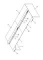
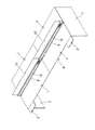
次に、添付図面に示した実施形態に基づき、本発明を更に詳細に説明する。図1〜図3は組立式デスクの天板の前縁部に小型の補助天板を取付けた状態を示し、図4及び図5は組立式デスクの天板の前縁部に大型の補助天板を取付けた状態を示し、図6〜図10は本発明の詳細を示し、図中符号1は天板、2は補助天板、3は支持アーム、4はベース杆、5は保持部材、6は支持杆をそれぞれ示している。
Next, the present invention will be described in more detail based on embodiments shown in the accompanying drawings. 1 to 3 show a state in which a small auxiliary top plate is attached to the front edge of the top of the assembly type desk. FIGS. 4 and 5 show large auxiliary tops on the front edge of the top of the assembly type desk. 6 to 10 show details of the present invention, wherein
本発明を適用する組立式デスクは、図1及び図4に示すように、少なくとも両端部に配する端部脚7,7、中間に配する中間脚8、前記端部脚7と中間脚8の間又は中間脚8と他の中間脚8の間を連結する脚間モジュール(図示せず)及び前記端部脚7と中間脚8の上面に前後に間隔を置いて載置して取付ける天板1,…を有するとともに、前後の天板1,1の間にダクト開口9を設け、該ダクト開口9の上方に電源用コンセントやLAN端子等の配線機能を備えた配線杆体10を懸架し、該配線杆体10の上面に棚板11を配置した構造である。また、図2に示した組立式デスクは、前記配線杆体10の上にフロントパネル12を配置した構造である。
As shown in FIGS. 1 and 4, the assembly type desk to which the present invention is applied includes
図1〜図3は、組立式デスクの天板1の前縁部の一側に、小型の前記補助天板2を2本の支持アーム3,3で支持して配置した実施形態を示し、図4及び図5は、組立式デスクの天板1の前縁部の一側に、大型の前記補助天板2の一端部を2本の支持アーム3,3で支持するとともに、該補助天板2の他端部を脚柱13で支持して配置した実施形態を示している。何れの実施形態の場合も、前記支持アーム3は同一部材であるので、以降の説明には区別なく説明する。
FIGS. 1 to 3 show an embodiment in which the small auxiliary
図3、図5〜図10に基づいて本発明を更に詳しく説明する。本発明は、デスクやテーブルの天板1の一部縁部に、該天板1の下面14に着脱可能に取付けた支持アーム3を介して支持した補助天板2を配置し、天板1を拡張して使用することが可能な補助天板装置であって、前記天板1の下面の前後部にスリット孔15,15を備え、前記支持アーム3は、前後部の前記スリット孔15,15にそれぞれ係止する前後一方向に向いた固定フック部16,16を設けるとともに、後部に前後変位可能且つ固定可能に設けた保持部材5に前記固定フック部16と前後逆方向に向いた可動フック部17を設けてなり、後部のスリット孔15に前記固定フック部16と可動フック部17を共に挿入状態で前後逆方向にスライドさせて該スリット孔15に抜け止め係合した状態で前記保持部材5を固定してなることを特徴としている。
The present invention will be described in more detail with reference to FIGS. According to the present invention, an auxiliary
具体的には、前記支持アーム3は、図3及び図6に示すように、前記天板1の下面14に取付けるベース杆4と、該ベース杆4の後部に前後変位可能且つ固定可能に設けた保持部材5と、該ベース杆4に後部を連結して前記天板1の縁部から突出した前部に前記補助天板2を載置して取付ける支持杆6とからなり、前記ベース杆4は、前後端部に前後部の前記スリット孔15,15にそれぞれ係止する前後一方向に向いた固定フック部16,16を設けている。尚、前記ベース杆4の前部に前記保持部材5を設けても良い。
Specifically, as shown in FIGS. 3 and 6, the
更に詳しくは、前記天板1の下面14には、前後部に前後方向を向いたスリット孔15,…をそれぞれ平行に二対設け、この二対のスリット孔15,…を横方向に所定間隔で複数設けている。前記スリット孔15は、本発明の支持アーム3を取付ける他に、天板1の下面14に引出しを設ける場合に、引出し枠体を取付けるためにも使用する。
More specifically, on the
前記ベース杆4は、両垂直板18,18と水平板19を有する上方開放の断面略コ字形の長尺部材であり、両垂直板18,18の前後端に上方へ突出した前向きの固定フック部16,16を二対設けたものである。前記保持部材5は、両側面板20,20と下面板21を有し、前記ベース杆4に外嵌可能な上方開放の断面略コ字形の短尺部材であり、両側面板20,20の後端に上方へ突出した後向きの可動フック部17,17を設けたものである。そして、前記保持部材5の下面板21に設けた前後方向に延びた長孔22に下方から挿通した段付きネジ23を前記ベース杆4の水平板19の螺孔24に螺合して、前記保持部材5を前記ベース杆4に対して前後変位可能とするとともに、前記下面板21に設けた通孔25に下方から挿通したネジ26を前記ベース杆4の水平板19に固着したナット27に螺合してベース杆4に対して保持部材5を固定可能としている。また、前記ベース杆4の水平板19の前部と中央部にもナット28,28を固着している。尚、当然ではあるが、前記ナット27,28の螺孔に対応する水平板19にはネジを挿通可能な孔を形成している。
The
そして、前記支持杆6は、上面側の中央部に沿って前記ベース杆4を受け入れる凹溝部29を有するとともに、両側縁に前記天板1の下面14に当接するとともに、前記補助天板2を載置する立上部30,30を有し、前記天板1の下面14に前記ベース杆4を取付けた状態で、前記支持杆6の凹溝部29内に前記ベース杆4を受け入れるとともに、前記支持杆6を下方から前記ベース杆4にネジ31,31で締結し、前記立上部30,30を前記天板1の下面14に圧接した状態で連結する。前記ベース杆4の前部に前記保持部材5を設けた場合には、前記支持杆6の後部の凹溝部29内に前記ベース杆4及び保持部材5を受け入れた状態で連結する。
The
更に詳しくは、前記支持杆6は、底面板32の両側縁に立上げた立上部30,30を有し、該立上部30,30の後部は前記天板1の下面14に当接するとともに、前部は前記補助天板2を載置し、両立上部30,30間には前記ベース杆4を受け入れる凹溝部29を有する形状である。そして、前記天板1の下面14に前記ベース杆4を取付けた状態で、前記支持杆6の凹溝部29内に前記ベース杆4を受け入れるとともに、前記支持杆6の底面板32に設けた通孔33,33に下方から挿通したネジ31,31を前記ベース杆4の水平板19に固着した前記ナット28,28の螺孔に螺合して引き付け、前記立上部30,30を前記天板1の下面14に圧接する。つまり、前記立上部30,30を前記天板1の下面14に圧接することを可能にするために、前記支持杆6をベース杆4に連結した状態で、前記ベース杆4の水平板19と前記支持杆6の底面板32との間には若干の隙間を設けている。
More specifically, the
ここで、前記支持杆6の前側の通孔33はダルマ孔となっており、前記ベース杆4の前部のナット28に予め緩くネジ31を螺合した状態で、前記支持杆6の前側のダルマ孔からなる通孔33を前記ネジ31の頭部に係止すれば、該支持杆6を仮支持することができ、後部の通孔33にネジ31を通してベース杆4の中間部のナット28に螺合する作業における位置決めが容易になる。また、前記ベース杆4の水平板19に前記ナット28,28を固着する代わりに、前記水平板19に直接螺孔又は下穴を設けることも可能であるが、締め付け強度の点でナット28を水平板19の上面に固着し、その螺孔に対応する水平板19に孔を設ける方が好ましい。
Here, the through
前記支持杆6の立上部30は、前記底面板32の側縁を直角に折曲して側壁板34を形成し、該側壁板34の上縁を内向きに直角に折曲して当止板35を形成し、更に該当止板35の内縁を下向きに直角に折曲して補強片36を形成した形状であり、両側の立上部30,30の補強片36,36間に前記ベース杆4の垂直板18,18が密接状態若しくは多少のクリアランスを有する状態で嵌合する。また、前記支持杆6の先端には、合成樹脂製のキャップ37が嵌着されている。
The rising
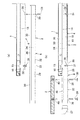
前記支持アーム3を前記天板1の下面14に取付けるには、先ず図7(a)に示すように、前記ベース杆4の後部に前記保持部材5を外嵌し、該保持部材5の下面板21に設けた長孔22に段付きネジ23を通して前記ベース杆4の水平板19に設けた螺孔24に螺合し、前記ベース杆4に対して保持部材5を前後スライド可能に取付け、更に前記ベース杆4の前部のナット28にネジ31を緩く螺合した状態で、前記保持部材5を前側へ移動させて前記ベース杆4の後端の固定フック部16と該保持部材5の可動フック部17を重ねて状態とし、前記ベース杆4の前端の固定フック部16を前記天板1の前部のスリット孔15に下方から挿入するとともに、前記ベース杆4の後端の固定フック部16と前記保持部材5の可動フック部17を前記天板1の後部のスリット孔15に同時に下方から挿入する。それから、図6(b)に示すように、前記ベース杆4を前方へスライドさせて前後の固定フック部16,16を前後部のスリット孔15,15の前縁部に係止する。最後に、図6(c)に示すように、前記ベース杆4に対して前記保持部材5を後方へスライドさせて前記可動フック部17を天板1の後部のスリット孔15の後縁部に係止した後、ネジ26を前記保持部材5の下面板21に設けた通孔25か挿入し、前記ベース杆4の水平板19の後部に固着したナット27に螺合して固定する。この状態で、前記ベース杆4は後方への変位が保持部材5によって規制されているので、前後部の固定フック部16,16が天板1のスリット孔15,15に係止した状態が確実に維持されるのである。
In order to mount the
前述のように、前記天板1の下面14に奥行方向に向けて前記ベース杆4を取付けた状態で、前記支持杆6を該ベース杆4に連結する。それには、図8(a)に示すように、前記支持杆6の凹溝部29内に前記ベース杆4を受け入れるとともに、前記ベース杆4の前部のナット28に緩く螺合しておいたネジ31を、前記支持杆6の前側のダルマ孔からなる通孔33に挿入し、該支持杆6を前後方向にスライドさせて通孔33に係止する。それから、後側の通孔33に挿通したネジ31を前記ベース杆4の中間部のナット28に螺合し、前側のネジ31も締め付ける。すると、前記支持杆6の両立上部30,30は前記天板1の下面14に圧接し、その反作用によって前記ベース杆4の両固定フック部16,16が前後部のスリット孔15,15にガタツキなく係合する。
As described above, the
このように、前記支持杆6の後部を前記ベース杆4に連結した状態で、図8(b)に示すように、前記天板1の前縁から前方へ突出した前記支持杆6の前部に前記補助天板2を載置して取付ける。具体的には、前記天板1の下面14に左右に間隔を置いて前記ベース杆4,4を取付け、それぞれに前記支持杆6,6を連結した状態で、各支持杆6の前部に前記補助天板2を載置するとともに、支持杆6の底面板32に設けた取付孔38,38に下方から挿通した固定ネジ39,39を前記補助天板2の下面に埋設したオニメナット40,40に螺合して支持する(図9及び図10参照)。尚、本発明では、前記支持杆6の前部の突出部に前記補助天板2を取付ける構造は任意である。本実施形態の補助天板2は木質系の構造としたので、前記オニメナット40,…を埋設したが、スチール系の構造であれば、下面板部に直接螺孔や下穴を形成してネジ又はタッピングネジを螺合することも、ナットを埋設してネジを螺合するものでも良い。また、その他の取付構造を採用することも可能である。
In this manner, with the rear part of the
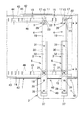
前記天板1の構造を図6及び図10に基づいて簡単に説明する。前記天板1は、スチール製であり、表面板41の周囲を下方に折曲して縁板部42を形成するとともに、前記表面板41の下面の前後端部に、下方に開口部45を向けた断面略C字形の補強部材43,43に固定し、更に裏面板44を前後の補強部材43,43に被さるように設けた構造である。そして、前記スリット孔15は、前記補強部材43の開口部45に合わせて前記裏面板44に形成し、該スリット孔15の前後部には前記補強部材43の折曲板46,46が位置し、前記固定フック部16や可動フック部17が係止するようになっており、支持強度を高めている。尚、前記天板1の裏面板44が前記下面14となっている。
The structure of the
1 天板、 2 補助天板、
3 支持アーム、 4 ベース杆、
5 保持部材、 6 支持杆、
7 端部脚、 8 中間脚、
9 ダクト開口、 10 配線杆体、
11 棚板、 12 フロントパネル、
13 脚柱、 14 下面、
15 スリット孔、 16 固定フック部、
17 可動フック部、 18 垂直板、
19 水平板、 20 側面板、
21 下面板、 22 長孔、
23 ネジ、 24 螺孔、
25 通孔、 26 ネジ、
27 ナット、 28 ナット、
29 凹溝部、 30 立上部、
31 ネジ、 32 底面板、
33 通孔、 34 側壁板、
35 当止板、 36 補強片、
37 キャップ、 38 取付孔、
39 固定ネジ、 40 オニメナット、
41 表面板、 42 縁板部、
43 補強部材、 44 裏面板、
45 開口部、 46 折曲板。
1 top plate, 2 auxiliary top plate,
3 support arm, 4 base rod,
5 holding member, 6 supporting rod,
7 end leg, 8 middle leg,
9 duct opening, 10 wiring rod,
11 shelf board, 12 front panel,
13 pillars, 14 underside,
15 slit hole, 16 fixed hook part,
17 movable hook part, 18 vertical plate,
19 horizontal plate, 20 side plate,
21 lower plate, 22 long hole,
23 screws, 24 screw holes,
25 through holes, 26 screws,
27 nuts, 28 nuts,
29 concave groove part, 30 rising part,
31 screws, 32 bottom plate,
33 through hole, 34 side wall plate,
35 Stop plate, 36 Reinforcement piece,
37 cap, 38 mounting hole,
39 fixing screw, 40 onime nut,
41 face plate, 42 edge plate part,
43 reinforcing member, 44 back plate,
45 opening, 46 bent plate.
Claims (5)
Priority Applications (1)
| Application Number | Priority Date | Filing Date | Title |
|---|---|---|---|
| JP2015219167A JP6638335B2 (en) | 2015-11-09 | 2015-11-09 | Auxiliary top device |
Applications Claiming Priority (1)
| Application Number | Priority Date | Filing Date | Title |
|---|---|---|---|
| JP2015219167A JP6638335B2 (en) | 2015-11-09 | 2015-11-09 | Auxiliary top device |
Publications (2)
| Publication Number | Publication Date |
|---|---|
| JP2017086387A JP2017086387A (en) | 2017-05-25 |
| JP6638335B2 true JP6638335B2 (en) | 2020-01-29 |
Family
ID=58769411
Family Applications (1)
| Application Number | Title | Priority Date | Filing Date |
|---|---|---|---|
| JP2015219167A Active JP6638335B2 (en) | 2015-11-09 | 2015-11-09 | Auxiliary top device |
Country Status (1)
| Country | Link |
|---|---|
| JP (1) | JP6638335B2 (en) |
-
2015
- 2015-11-09 JP JP2015219167A patent/JP6638335B2/en active Active
Also Published As
| Publication number | Publication date |
|---|---|
| JP2017086387A (en) | 2017-05-25 |
Similar Documents
| Publication | Publication Date | Title |
|---|---|---|
| JP4518972B2 (en) | Top plate support structure | |
| JP6638335B2 (en) | Auxiliary top device | |
| JP5516517B2 (en) | Desktop panel mounting device | |
| JP2015104584A (en) | Knockdown desk | |
| JP2008119407A (en) | Desk apparatus with wing | |
| JP5540999B2 (en) | Side panel mounting device | |
| JP2010125015A (en) | Desk panel and mounting structure for the same | |
| JP5304014B2 (en) | Desktop panel mounting device | |
| JP5275405B2 (en) | Desk leg equipment | |
| JP5976341B2 (en) | table | |
| JP2017195930A (en) | Shelf device | |
| JP4782567B2 (en) | Mounting structure of shelf board to partition panel | |
| JP2009285346A (en) | Side panel mounting structure and bracket | |
| JP2004121694A (en) | Knockdown desk system | |
| JP6649074B2 (en) | Attachment structure of extension top plate, furniture with top plate provided with the same, and method of attaching extension top plate | |
| JP2008104711A (en) | Device for attaching hanging beam between existing posts | |
| JP5262832B2 (en) | Desk panel mounting structure | |
| JP2009261841A5 (en) | ||
| JP4650389B2 (en) | Prop standing device on a plate such as a tabletop | |
| JP2009209597A (en) | Wall material and mounting bracket therefor | |
| JP4800005B2 (en) | Furniture legs | |
| JP2008049182A (en) | Knockdown desk | |
| JP2004016402A (en) | Fixing device for shelf board | |
| JP2004016403A (en) | Device for attaching light to shelf board | |
| JP6361780B2 (en) | Assembling desk |
Legal Events
| Date | Code | Title | Description |
|---|---|---|---|
| A621 | Written request for application examination |
Free format text: JAPANESE INTERMEDIATE CODE: A621 Effective date: 20181102 |
|
| TRDD | Decision of grant or rejection written | ||
| A01 | Written decision to grant a patent or to grant a registration (utility model) |
Free format text: JAPANESE INTERMEDIATE CODE: A01 Effective date: 20191126 |
|
| A61 | First payment of annual fees (during grant procedure) |
Free format text: JAPANESE INTERMEDIATE CODE: A61 Effective date: 20191209 |
|
| R150 | Certificate of patent or registration of utility model |
Ref document number: 6638335 Country of ref document: JP Free format text: JAPANESE INTERMEDIATE CODE: R150 |
|
| R250 | Receipt of annual fees |
Free format text: JAPANESE INTERMEDIATE CODE: R250 |
|
| R250 | Receipt of annual fees |
Free format text: JAPANESE INTERMEDIATE CODE: R250 |