JP2015104584A - Knockdown desk - Google Patents

Knockdown desk Download PDF

Info

Publication number
JP2015104584A
JP2015104584A JP2013248743A JP2013248743A JP2015104584A JP 2015104584 A JP2015104584 A JP 2015104584A JP 2013248743 A JP2013248743 A JP 2013248743A JP 2013248743 A JP2013248743 A JP 2013248743A JP 2015104584 A JP2015104584 A JP 2015104584A
Authority
JP
Japan
Prior art keywords
leg
plate
legs
plates
intermediate leg
Prior art date
Legal status (The legal status is an assumption and is not a legal conclusion. Google has not performed a legal analysis and makes no representation as to the accuracy of the status listed.)
Pending
Application number
JP2013248743A
Other languages
Japanese (ja)
Inventor
太祐 村山
Tasuke Murayama
太祐 村山
Current Assignee (The listed assignees may be inaccurate. Google has not performed a legal analysis and makes no representation or warranty as to the accuracy of the list.)
Itoki Corp
Itoki All Steel Co Ltd
Original Assignee
Itoki Corp
Itoki All Steel Co Ltd
Priority date (The priority date is an assumption and is not a legal conclusion. Google has not performed a legal analysis and makes no representation as to the accuracy of the date listed.)
Filing date
Publication date
Application filed by Itoki Corp, Itoki All Steel Co Ltd filed Critical Itoki Corp
Priority to JP2013248743A priority Critical patent/JP2015104584A/en
Publication of JP2015104584A publication Critical patent/JP2015104584A/en
Pending legal-status Critical Current

Links

Images

Landscapes

  • Tables And Desks Characterized By Structural Shape (AREA)

Abstract

PROBLEM TO BE SOLVED: To provide a knockdown desk consisting of minimum necessary basic components, having lateral extensibility and high workability, capable of further reducing the cost and also having extensibility by an additional option.SOLUTION: The knockdown desk includes: end-part legs 1 disposed at least both ends; an intermediate leg 2 having a substantially T shape in side view, disposed at an intermediate part, and consisting of a leg column 6 and a support arm 7; a pair of front/rear beam plates 3 for connecting between the end legs and the intermediate leg, or between the intermediate leg and another intermediate leg; and top boards 4 provided on the upper faces of the end-part legs and the intermediate legs, at some interval apart in the front/rear direction. The pair of beam plates are disposed at some interval apart in the front/rear direction and connected to the end-part legs or the intermediate legs respectively. A duct space 9 formed between both beam plates is located beneath a duct opening 8 formed between the front/rear top boards, and a duct cover 5 is demountably mounted on the duct opening.

Description

本発明は、組立式デスクに係わり、更に詳しくはノックダウン方式で側方への拡張性を備えた組立式デスクに関するものである。   The present invention relates to an assembling desk, and more particularly to an assembling desk with a knock-down method and lateral expansion.

従来から、端部脚と中間脚と、その間を連結する連結部材と、天板とからなり、中間脚を介して同一脚間距離で次々に天板を側方へ連設する構造の組立式デスクは各種提供されている。   Conventionally, it is composed of an end leg, an intermediate leg, a connecting member that connects between the end leg, and a top plate. The assembly type has a structure in which the top plate is continuously connected to the side through the intermediate leg one after another at the same distance between the legs. Various desks are provided.

例えば、本出願人に係る特許文献1には、少なくとも両端部に配する端部脚、中間に配する中間脚、前記端部脚と中間脚の間又は中間脚と他の中間脚の間を連結する脚間モジュール及び前記端部脚と中間脚の上面に前後に間隔を置いて載置して取付ける天板を有するとともに、前後の天板の間の下方に前記脚間モジュールに備えたダクト開口が位置する組立式デスクが開示されている。   For example, Patent Document 1 related to the present applicant includes at least end legs disposed at both ends, intermediate legs disposed in the middle, between the end legs and the intermediate legs or between the intermediate legs and the other intermediate legs. The inter-leg module to be connected and a top plate mounted on the upper surface of the end leg and the intermediate leg with a space in the front-rear direction, and a duct opening provided in the inter-leg module is provided below the front and rear top plates. A positionable assembly desk is disclosed.

更に詳しくは、特許文献1に記載の組立式デスクは、天板は全て同一横幅であり、中間脚は、脚柱と支持アームからなる側面視略T字形であるとともに、その横幅を前記端部脚の横幅の2倍に設定したものであり、脚間モジュールは、前後に間隔を隔てて配する両ビーム板と、両ビーム板の両端上部間を連結する連結板とからなり、前記ビーム板は上下を内側に折り曲げるとともに、端面に断面L字形部材を固定して連結片を形成し、両ビーム板に固定した断面L字形部材の上部間を前記連結板で連結して上下貫通したダクト開口を形成するとともに、両端部において両連結片と連結板とで前記ダクト開口に連通して横方向に開放した開口部を形成させ、更に前記端部脚と中間脚の間及び隣り合う両中間脚の間で同一長さとしたものであり、前記天板の下面側縁を、前記端部脚の上面に天板の側端面と端部脚の外側面が面一となるように載置するとともに、前記中間脚の上面に天板の側端面と中間脚の中心線が一致するように載置して取付手段にて取付け、中間脚の位置における天板同士の側端面を直接接合するものである。   More specifically, in the assembling desk described in Patent Document 1, all the top plates have the same horizontal width, and the intermediate leg has a substantially T-shape in a side view including a pedestal and a support arm, and the horizontal width is the end portion. The leg module is configured to be twice the lateral width of the leg, and the inter-leg module is composed of both beam plates arranged at intervals in the front and rear direction, and a connecting plate for connecting the upper ends of both beam plates. Is a duct opening that is bent vertically inward and has L-shaped members fixed to the end faces to form connecting pieces, and the upper portions of the L-shaped members fixed to both beam plates are connected by the connecting plates. And at both ends, both connecting pieces and connecting plates are connected to the duct openings to form laterally open openings, and further between the end legs and the intermediate legs and between the adjacent intermediate legs. Between the same length, The bottom surface side edge of the top plate is placed on the top surface of the end leg so that the side end surface of the top plate and the outer surface of the end leg are flush with each other, and on the top surface of the intermediate leg The end surfaces are placed so that the center lines of the intermediate legs coincide with each other and attached by attachment means, and the side end surfaces of the top plates at the positions of the intermediate legs are directly joined.

前述の特許文献1に記載のコンセプトの組立式デスクは、構造が単純、組立施工も簡単、比較的低コストであることから、市場において好評を博しているところであり、他社も追随しているところであるが、課題も若干ある。つまり、脚間モジュールは、前後に間隔を隔てて配した両ビーム板の両端間を連結板で連結した構造であるので、嵩張ることは否めず、保管や搬送における空間効率を悪くする原因となっていた。   The assembly desk of the concept described in the above-mentioned Patent Document 1 has gained popularity in the market because of its simple structure, simple assembly work, and relatively low cost, and other companies are also following. By the way, there are some problems. In other words, the inter-leg module has a structure in which both ends of both beam plates arranged at intervals in the front and rear are connected by a connecting plate, so it cannot be overwhelmed, and it causes a decrease in space efficiency in storage and transportation. It was.

特開2007−151824号公報JP 2007-151824 A

そこで、本発明が前述の状況に鑑み、解決しようとするところは、必要最小限の基本構成部品からなるノックダウン方式で側方への拡張性を備え、施工性にも優れ、更なるコスト低減化を図ることが可能であり、追加オプションによる拡張性も有する組立式デスクを提供する点にある。   Therefore, in view of the above-mentioned situation, the present invention intends to solve the problem by providing a knockdown method composed of the minimum necessary basic components, and has lateral expandability, excellent workability, and further cost reduction. Therefore, it is possible to provide an assembly desk that can be expanded and can be expanded by additional options.

本発明は、前述の課題解決のために、少なくとも両端部に配する端部脚、中間に配し、脚柱と1本の支持アームからなる側面視略T字形の中間脚、前記端部脚と中間脚の間又は中間脚と他の中間脚の間を連結する前後一対のビーム板及び前記端部脚と中間脚の上面に前後に間隔を置いて載置して取付ける天板とを有し、一対の前記ビーム板を前後に間隔を隔てて配置してそれぞれ前記端部脚又は前記中間脚に連結するとともに、前後の天板間のダクト開口の下方に両ビーム板間に形成するダクト空間が位置し、前記ダクト開口にはダクトカバーを着脱可能に装着することを特徴とする組立式デスクを構成した(請求項1)。   In order to solve the above-described problems, the present invention provides an end leg disposed at least at both ends, an intermediate leg disposed in the middle and having a pedestal and a single support arm in a side view, and the end legs. A pair of front and rear beam plates that connect between the intermediate leg or between the intermediate leg and the other intermediate leg, and a top plate that is placed on the upper surface of the intermediate leg and spaced from the front and back. And a pair of beam plates arranged at intervals in the front-rear direction and connected to the end legs or the intermediate legs, respectively, and a duct formed between the beam plates below the duct opening between the front and rear top plates. An assembly type desk is characterized in that a space is located and a duct cover is detachably attached to the duct opening.

ここで、前記ビーム板は、垂直な幕板の上下縁を内方に折曲して上下補強縁を形成するとともに、前記幕板の両端部内側に垂直な取付端板を有する連結部材を固着し、該取付端板を前記端部脚又は前記中間脚の側面上部にネジ止めしてなるものである(請求項2)。   Here, the beam plate is bent inward at the upper and lower edges of the vertical curtain plate to form upper and lower reinforcing edges, and a connecting member having a vertical attachment end plate is fixed inside the both ends of the curtain plate. And this attachment end plate is screwed to the side part upper part of the said end leg or the said intermediate leg (Claim 2).

また、前記端部脚及び前記中間脚の側面に沿った位置で、前記ビーム板間の上部にわたって受部材を取付け、該受部材に机上パネルの支持部材を取付けるとともに、前記ダクト開口の上位に左右両側の支持部材で机上パネルを支持してなることも好ましい(請求項3)。   In addition, a receiving member is attached to the upper part between the beam plates at positions along the side surfaces of the end leg and the intermediate leg, and a support member for a desktop panel is attached to the receiving member, and the upper and lower sides of the duct opening are It is also preferable that the desktop panel is supported by support members on both sides.

更に、前記受部材は、垂直な基板の上縁を直角に折曲して前記支持部材を取付ける取付板を形成するとともに、前記基板の両側下端部に下方へ開放したU字溝を形成し、前記ビーム板を前記端部脚又は前記中間脚に取付けるネジに両U字溝を係合し、該ビーム板と共締めしてなることがより好ましい(請求項4)。   Furthermore, the receiving member bends the upper edge of the vertical substrate at a right angle to form a mounting plate for mounting the support member, and forms U-shaped grooves opened downward at the lower ends on both sides of the substrate, More preferably, the U-groove is engaged with a screw for attaching the beam plate to the end leg or the intermediate leg, and is fastened together with the beam plate.

以上にしてなる請求項1に係る発明の組立式デスクによれば、少なくとも両端部に配する端部脚、中間に配し、脚柱と1本の支持アームからなる側面視略T字形の中間脚、前記端部脚と中間脚の間又は中間脚と他の中間脚の間を連結する前後一対のビーム板及び前記端部脚と中間脚の上面に前後に間隔を置いて載置して取付ける天板とを有し、一対の前記ビーム板を前後に間隔を隔てて配置してそれぞれ前記端部脚又は前記中間脚に連結するとともに、前後の天板間のダクト開口の下方に両ビーム板間に形成するダクト空間が位置し、前記ダクト開口にはダクトカバーを着脱可能に装着するので、必要最小限の基本構成部品からなるノックダウン方式で側方への拡張性を備え、施工性にも優れている効果の他に、一対のビーム板を重ねれば空間の利用効率が上がり、また梱包材の節約もでき、保管、搬送のコストを低減することができ、基本構成のデスクのコスト低減化にも寄与するのである。   According to the assembly type desk of the invention according to claim 1 as described above, at least the end legs arranged at both ends, the middle of the leg, and the middle of the T-shaped view including the pedestal and one support arm. Legs, a pair of front and rear beam plates connecting between the end legs and the intermediate legs or between the intermediate legs and the other intermediate legs, and placed on the upper surfaces of the end legs and the intermediate legs with a space in the front and rear direction A pair of beam plates arranged at a distance in the front-rear direction and connected to the end legs or the intermediate legs, respectively, and both beams below the duct opening between the front and rear top plates. The duct space formed between the plates is located, and the duct cover is detachably attached to the duct opening, so it has a side-by-side expandability with the minimum required basic components and is easy to install. In addition to the excellent effect, if a pair of beam plates are stacked, Utilization efficiency is increased, and also can save packaging, storage, it is possible to reduce the cost of transport, it is to contribute to the cost reduction of the desk base configuration.

請求項2によれば、前記ビーム板は、垂直な幕板の上下縁を内方に折曲して上下補強縁を形成するとともに、前記幕板の両端部内側に垂直な取付端板を有する連結部材を固着し、該取付端板を前記端部脚又は前記中間脚の側面上部にネジ止めしてなるので、ビーム板は偏平な形状であるので、取り扱いが容易であり、脚間に前後一対連結した状態では、剛性が高い構造となり、安定に天板を支持することができる。   According to a second aspect of the present invention, the beam plate has upper and lower edges bent vertically inward to form upper and lower reinforcing edges, and has vertical mounting end plates on both inner sides of the curtain plate. The connecting member is fixed and the mounting end plate is screwed to the upper side of the end leg or the intermediate leg, so the beam plate is flat and easy to handle. In a pair-connected state, the structure is highly rigid and the top plate can be stably supported.

請求項3によれば、前記端部脚及び前記中間脚の側面に沿った位置で、前記ビーム板間の上部にわたって受部材を取付け、該受部材に机上パネルの支持部材を取付けるとともに、前記ダクト開口の上位に左右両側の支持部材で机上パネルを支持してなるので、机上パネルが必要な場合にのみオプションとして受部材を取付けて、机上パネルの支持部材を取付けることができ、基本構成がより単純になるのでコスト低減化に寄与するとともに、オプションによる拡張性をも確保できる。   According to a third aspect of the present invention, a receiving member is attached to an upper portion between the beam plates at positions along the side surfaces of the end leg and the intermediate leg, and a support member for a desktop panel is attached to the receiving member. Since the desktop panel is supported by support members on both the left and right sides above the opening, a receiving member can be attached as an option only when a desktop panel is required, and the desktop panel support member can be attached. This simplifies the process and contributes to cost reduction, while ensuring expandability with options.

請求項4によれば、前記受部材は、垂直な基板の上縁を直角に折曲して前記支持部材を取付ける取付板を形成するとともに、前記基板の両側下端部に下方へ開放したU字溝を形成し、前記ビーム板を前記端部脚又は前記中間脚に取付けるネジに両U字溝を係合し、該ビーム板と共締めしてなるので、受部材を簡単に取付けることができ、また受部材の取付状態は極めて安定であるので、支持部材を介して机上パネルを安定に支持でき、更に追加部品点数も最小となってコスト低減化に寄与する。   According to a fourth aspect of the present invention, the receiving member bends an upper edge of a vertical substrate at a right angle to form a mounting plate for mounting the support member, and is U-shaped opened downward at both lower ends of the substrate. A groove is formed, and both U-shaped grooves are engaged with a screw for attaching the beam plate to the end leg or the intermediate leg, and are fastened together with the beam plate, so that the receiving member can be easily attached. Moreover, since the mounting state of the receiving member is extremely stable, the desktop panel can be stably supported via the support member, and the number of additional parts is minimized, contributing to cost reduction.

本発明の組立式デスクの構成例を示す斜視図である。It is a perspective view which shows the structural example of the assembly-type desk of this invention. 同じく部分分解斜視図である。It is a partially exploded perspective view of the same. 同じく端部脚と中間脚をビーム板で連結した後、天板を取付ける状態の部分分解斜視図である。Similarly, after connecting the end legs and the intermediate legs with a beam plate, it is a partially exploded perspective view of a state in which the top plate is attached. 端部脚にビーム板を連結する状態の部分分解斜視図である。It is a partial exploded perspective view in the state where a beam plate is connected to an end leg. 端部脚にビーム板を連結した状態の部分斜視図である。It is a fragmentary perspective view in the state where a beam plate was connected to an end leg. 中間脚の部分分解斜視図である。It is a partial exploded perspective view of an intermediate leg. 組立式デスクの縦断側面図である。It is a vertical side view of an assembly-type desk. ダクト部分の拡大縦断面図である。It is an expansion longitudinal cross-sectional view of a duct part. 机上パネルを備えた組立式デスクの構成例を示す斜視図である。It is a perspective view which shows the structural example of the assembly-type desk provided with the desk top panel. 同じく受部材と机上パネルの支持部材の関係を示す拡大部分斜視図である。It is an enlarged partial perspective view which similarly shows the relationship between a receiving member and the support member of a desktop panel. 机上パネルの支持構造を示す部分省略斜視図である。It is a partial omission perspective view which shows the support structure of a desktop panel. 両側の支持部材に机上パネルを支持する状態の分解斜視図である。It is a disassembled perspective view of the state which supports a desktop panel in the supporting member of both sides. 机上パネルを備えた組立式デスクの縦断側面図である。It is a vertical side view of the assembly-type desk provided with the desk top panel. ダクト部分の拡大縦断面図である。It is an expansion longitudinal cross-sectional view of a duct part.

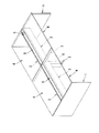
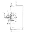
次に、添付図面に示した実施形態に基づき、本発明を更に詳細に説明する。図1は本発明に係る組立式デスクを示し、図2〜図8はその詳細を示し、図9〜図14は机上パネルを備えた組立式デスクを示し、図中符号1は端部脚、2は中間脚、3はビーム板、4は天板、5はダクトカバーをそれぞれ示している。   Next, the present invention will be described in more detail based on the embodiments shown in the accompanying drawings. FIG. 1 shows an assembly desk according to the present invention, FIGS. 2 to 8 show the details thereof, FIGS. 9 to 14 show an assembly desk with a desktop panel, and reference numeral 1 in FIG. 2 is an intermediate leg, 3 is a beam plate, 4 is a top plate, and 5 is a duct cover.

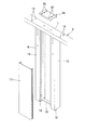
本発明に係る組立式デスクは、少なくとも両端部に配する端部脚1,1、中間に配し、脚柱6と1本の支持アーム7からなる側面視略T字形の中間脚2、前記端部脚1と中間脚2の間又は中間脚2と他の中間脚2の間を連結する前後一対のビーム板3,3及び前記端部脚1と中間脚2の上面に前後に間隔を置いて載置して取付ける天板4とを有し、一対の前記ビーム板3,3を前後に間隔を隔てて配置してそれぞれ前記端部脚1又は前記中間脚2に連結するとともに、前後の天板4,4間のダクト開口8の下方に両ビーム板3,3間に形成するダクト空間9が位置し、前記ダクト開口8にはダクトカバー5を着脱可能に装着するものである。   The assembly-type desk according to the present invention includes at least end legs 1 and 1 disposed at both ends, and an intermediate leg 2 having a substantially T-shape in a side view, which includes a leg column 6 and one support arm 7. A pair of front and rear beam plates 3 and 3 connecting between the end leg 1 and the intermediate leg 2 or between the intermediate leg 2 and the other intermediate leg 2 and the top surface of the end leg 1 and the intermediate leg 2 are spaced forward and backward. A top plate 4 to be placed and mounted, and a pair of the beam plates 3 and 3 are arranged at intervals in the front-rear direction and connected to the end leg 1 or the intermediate leg 2, respectively, A duct space 9 formed between the beam plates 3 and 3 is positioned below the duct opening 8 between the top plates 4 and 4, and the duct cover 5 is detachably mounted on the duct opening 8.

前記端部脚1は、図2に示すように、側面視四角形の板状のものであり、上端に天板4を取付ける取付金具10,…を内方へ向けて前後に4つ固定している。前記端部脚1は、前後両端の内面側を約45度に面取りして、外観性においてシャープなイメージを醸し出している。前記取付金具10は、図5に示すように、L字形のアングル材であり、該取付金具10を取付ける前記端部脚1の上端内側コーナー部には切欠孔11を形成し、該取付金具10の垂直片10Aを前記切欠孔11に挿入し、端部脚1の内面側から挿入したネジ12を垂直片10Aに螺合して取付けると、水平片10Bが端部脚1の上面と面一となって内方へ向いた突出する。前記取付金具10の水平片10Bには取付孔13が形成されている。   As shown in FIG. 2, the end leg 1 has a rectangular plate shape when viewed from the side, and has four mounting brackets 10 for attaching the top plate 4 to the upper end thereof fixed in the front and rear direction. Yes. The end leg 1 chamfers the inner surfaces of the front and rear ends at about 45 degrees to create a sharp image in appearance. As shown in FIG. 5, the mounting bracket 10 is an L-shaped angle member, and a notch hole 11 is formed in an upper-end inner corner portion of the end leg 1 to which the mounting bracket 10 is attached. When the vertical piece 10A is inserted into the notch hole 11 and the screw 12 inserted from the inner surface side of the end leg 1 is screwed onto the vertical piece 10A and attached, the horizontal piece 10B is flush with the upper surface of the end leg 1. And projecting inward. A mounting hole 13 is formed in the horizontal piece 10 </ b> B of the mounting bracket 10.

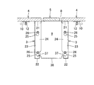
また、前記中間脚2は、図2、図3及び図6に示すように、脚柱6と前後方向に延びた1本の支持アーム7とからなる側面視略T字形を有し、前記支持アーム7の横幅は端部脚1の横幅の2倍に設定している。尚、前記支持アーム7には、前記端部脚1の取付金具10の取付孔13に対応させて、上下貫通した貫通孔14,…を2つずつ並べて4箇所に形成している。更に詳しくは、前記中間脚2の脚柱6は、前後一対の脚杆15,15を間隔を隔てて前記支持アーム7の中央部下側に固定するとともに、脚杆15,15の下端間を結合片16で連結して一体化し、更に両脚杆15,15の上部を余して脚カバー17,17を両側に着脱可能に嵌着している。また、前記端部脚1の下端及び前記中間脚2の脚柱6の下端には適宜アジャスター18,…を設けるものとする。ここで、前記脚カバー17より上方の両脚杆15,15の間は前記ダクト空間9に連通するダクト開口部19となる。   Further, as shown in FIGS. 2, 3 and 6, the intermediate leg 2 has a substantially T-shape in a side view including a leg post 6 and a single support arm 7 extending in the front-rear direction. The lateral width of the arm 7 is set to twice the lateral width of the end leg 1. The support arm 7 is formed with four through-holes 14 penetrating vertically so as to correspond to the mounting holes 13 of the mounting bracket 10 of the end leg 1 at four locations. More specifically, the column 6 of the intermediate leg 2 fixes the pair of front and rear leg rods 15 and 15 to the lower side of the center portion of the support arm 7 with a space therebetween, and connects the lower ends of the leg rods 15 and 15. The pieces 16 are connected and integrated with each other, and the leg covers 17 and 17 are detachably fitted to both sides with the upper portions of both leg rods 15 and 15 remaining. Further, adjusters 18 are appropriately provided at the lower end of the end leg 1 and the lower end of the pedestal 6 of the intermediate leg 2. Here, a space between both leg rods 15, 15 above the leg cover 17 is a duct opening 19 that communicates with the duct space 9.

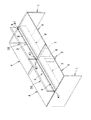
前記ビーム板3は、図2、図4及び図5に示すように、垂直な幕板20の上下縁を内方に折曲して上下補強縁21,22を形成するとともに、前記幕板20の両端部内側にアングル材からなる連結部材23を固着したものである。ここで、前記連結部材23の垂直な取付端板24がビーム板3の端面に一致するようにしている。前記連結部材23の取付端板24の上下部にダルマ孔25,25を形成している。   As shown in FIGS. 2, 4 and 5, the beam plate 3 bends the upper and lower edges of the vertical curtain plate 20 inward to form upper and lower reinforcing edges 21 and 22. The connecting member 23 made of an angle material is fixed to the inner side of the both ends. Here, the vertical attachment end plate 24 of the connecting member 23 is made to coincide with the end surface of the beam plate 3. Dalma holes 25 and 25 are formed in the upper and lower portions of the attachment end plate 24 of the connecting member 23.

そして、図4に示すように、前記端部脚1の内側面の上部に、前記ビーム板3の取付端板24に形成した両ダルマ孔25,25に対応させて頭部付き連結ネジ26,26を突設する。同様に、前記中間脚2の脚柱6を構成する脚杆15,15の上部両側面にも頭部付き連結ネジ26,26を突設する。   Then, as shown in FIG. 4, on the upper part of the inner side surface of the end leg 1, the head-attached connection screws 26, corresponding to both Dharma holes 25, 25 formed in the mounting end plate 24 of the beam plate 3, 26 is projected. Similarly, connecting screws with heads 26, 26 are provided on both side surfaces of the upper portions of the leg rods 15, 15 constituting the column 6 of the intermediate leg 2.

前記天板4の構造は特に限定されないが、スチール製の表面板と裏面板の間にハニカムを介在させ、その周囲に合成樹脂製の低発泡体、あるいは中質繊維板(MDF)等を配して芯材とした構造のものを用いた。また、スチール製の表面板と裏面板の間に直接低発泡の合成樹脂製の芯材を発泡形成することも可能である。更には、前記天板4は木質系の中実構造のものでも良い。そして、前記天板4の下面の両側端縁の前後部であって、前記取付金具10,10の取付孔13,13、中間脚2の支持アーム7に形成した貫通孔14,14に対応する位置に螺孔27,27を形成している。   Although the structure of the top plate 4 is not particularly limited, a honeycomb is interposed between the steel front plate and the back plate, and a synthetic resin low foam or medium fiber board (MDF) is arranged around the honeycomb. A structure having a core material was used. It is also possible to directly form a low foaming synthetic resin core between the steel front plate and the back plate. Furthermore, the top plate 4 may have a solid wood structure. And it corresponds to the front and rear portions of the both side edges of the lower surface of the top plate 4 and the through holes 14 and 14 formed in the mounting holes 13 and 13 of the mounting brackets 10 and 10 and the support arm 7 of the intermediate leg 2. Screw holes 27 are formed at the positions.

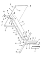
このような各部品を用いて本実施形態に係る組立式デスクを施工するには、先ず図2及び図4に示すように、前記端部脚1を立起状態にして、前記ビーム板3の一方の連結部材23に形成したダルマ孔25,25を前記端部脚1の内側面に突設した頭部付き連結ネジ26,26に係止し、それから連結ネジ26を締め付ける。同様に、もう一枚のビーム板3を前記端部脚1の内側面に連結する。次に、前記中間脚2を立起状態にして、両ビーム板3,3の連結部材23,23に設けたダルマ孔25,…を予め脚柱6に緩く螺着していた連結ネジ26,…に係止した後、締め付けて連結する。この状態で前後一対のビーム板3,3間にはダクト空間9が形成される。次に、図3に示すように、前記端部脚1と中間脚2の上面に天板4の下面両側縁を載置し、前記端部脚1に設けた取付金具10,10の取付孔13,13と中間脚2の支持アーム7に形成した貫通孔14,14に、下方からネジ28,…を挿通して前記天板4の螺孔27,…に螺合する。   In order to construct the assembly desk according to the present embodiment using each of these parts, first, as shown in FIGS. 2 and 4, the end leg 1 is raised and the beam plate 3 The dharma holes 25, 25 formed in one of the connecting members 23 are engaged with the head-attached connecting screws 26, 26 protruding from the inner surface of the end leg 1, and then the connecting screw 26 is tightened. Similarly, another beam plate 3 is connected to the inner surface of the end leg 1. Next, with the intermediate leg 2 in an upright state, the connection screws 26, which have been loosely screwed into the pedestal 6 in advance in the dharma holes 25,... Provided in the connection members 23, 23 of the beam plates 3, 3. After locking to ..., tighten and connect. In this state, a duct space 9 is formed between the pair of front and rear beam plates 3 and 3. Next, as shown in FIG. 3, both side edges of the lower surface of the top plate 4 are placed on the upper surfaces of the end legs 1 and the intermediate legs 2, and mounting holes for mounting brackets 10, 10 provided on the end legs 1 are mounted. 13 and 13 and the through-holes 14 and 14 formed in the support arm 7 of the intermediate leg 2 are screwed into the screw holes 27 and so on of the top plate 4 by inserting screws 28 and so on from below.

それから、前記中間脚2の他の側面に、他のビーム板3,3の一端部を前記同様に連結するとともに、該ビーム板3,3の他端部に前記同様に中間脚2又は端部脚1を連結する。このように、次々と側方へビーム板3,3、中間脚2、天板4を連結していき、最後に端部脚1を連結するのである。   Then, one end portion of the other beam plates 3 and 3 is connected to the other side surface of the intermediate leg 2 in the same manner as described above, and the intermediate leg 2 or end portion is connected to the other end portion of the beam plates 3 and 3 in the same manner as described above. The legs 1 are connected. In this way, the beam plates 3 and 3, the intermediate leg 2, and the top plate 4 are connected one after the other, and finally the end leg 1 is connected.

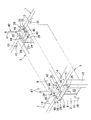
更に、前記端部脚1の上面であって前後の天板4,4間には、図5に示すように、端金具29を取付ける。この端金具29は、水平な取付板30の外側に当止片31を立上げるとともに、取付板30の前後部に端部を余して突片32,32を切り起し形成したものであり、前記取付板30を前記端部脚1の上面にネジ33,33で取付ける。前記端金具29の当止片31は、前記ダクトカバー5のズレを規制する。また、前記中間脚2の支持アーム7の上面であって前後の天板4,4間には、図6に示すように、中間金具34を取付ける。前記中間金具34は断面略コ字形で前記支持アーム7の上面及び両側面に被さるように取付ける。前記中間金具34の上面には、前記端金具29の突片32,32と同じ間隔で二対の突起35,35を突設している。これら、突片32,32や突起35,35は、前記ダクトカバー5を所定の位置に正確に載支するのに利用する。つまり、前後の天板4,4の端部とダクトカバー5の間に、それぞれ配線コードを挿通するための隙間を形成するのである。   Further, as shown in FIG. 5, an end fitting 29 is attached on the upper surface of the end leg 1 between the front and rear top plates 4 and 4. The end fitting 29 is formed by raising a stopper piece 31 on the outer side of a horizontal mounting plate 30 and cutting and protruding the protruding pieces 32, 32 leaving the end portions at the front and rear portions of the mounting plate 30. The mounting plate 30 is attached to the upper surface of the end leg 1 with screws 33 and 33. The stopper piece 31 of the end fitting 29 restricts the displacement of the duct cover 5. Further, as shown in FIG. 6, an intermediate metal fitting 34 is attached on the upper surface of the support arm 7 of the intermediate leg 2 and between the front and rear top plates 4, 4. The intermediate metal fitting 34 has a substantially U-shaped cross section and is attached so as to cover the upper surface and both side surfaces of the support arm 7. Two pairs of protrusions 35, 35 protrude from the upper surface of the intermediate metal 34 at the same interval as the protruding pieces 32, 32 of the end metal fitting 29. These protrusions 32 and 32 and protrusions 35 and 35 are used to accurately support the duct cover 5 at a predetermined position. That is, a gap for inserting the wiring cord is formed between the ends of the front and rear top plates 4 and 4 and the duct cover 5.

このように組立てたデスクは、図7及び図8に示すように、前後一対のビーム板3,3の間にダクト空間9が形成される。そこで、両ビーム板3,3の下側補強縁22,22に所定長さのコード受け36を適数係止し、配線コードを受けることができるようにしている。前記コード受け36は、トレーを構成し、両側縁に形成した係止部37,37を前記ビーム板3,3の下側補強縁22,22に係止するようにしている。   In the desk assembled in this way, a duct space 9 is formed between the pair of front and rear beam plates 3 and 3 as shown in FIGS. Therefore, an appropriate number of cord receivers 36 of a predetermined length are locked to the lower reinforcing edges 22 and 22 of both beam plates 3 and 3 so that the wiring cords can be received. The cord receiver 36 constitutes a tray, and latches 37 and 37 formed on both side edges are latched to the lower reinforcing edges 22 and 22 of the beam plates 3 and 3.

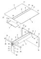
次に、図9〜図14に基づいて、オプションとして、前後の天板4,4の中間に机上パネル38を支持する場合を説明する。つまり、前記端部脚1及び前記中間脚2の側面に沿った位置で、前記ビーム板3,3間の上部にわたって受部材39,39を取付け、該受部材39に机上パネル38の支持部材40を取付けるとともに、前記ダクト開口8の上位に左右両側の支持部材40,40で机上パネル38を支持してなる。   Next, based on FIGS. 9-14, the case where the desk top panel 38 is supported in the middle of the front and back top plates 4 and 4 as an option is demonstrated. That is, receiving members 39 are attached to the upper portions between the beam plates 3 and 3 at positions along the side surfaces of the end leg 1 and the intermediate leg 2, and the support member 40 of the desktop panel 38 is attached to the receiving member 39. The desktop panel 38 is supported by support members 40 on the left and right sides above the duct opening 8.

ここで、前記受部材39は、図10に示すように、垂直な基板41の上縁を直角に折曲して前記支持部材40を取付ける取付板42を形成するとともに、前記基板41の両側下端部に下方へ開放したU字溝43,43を形成し、前記ビーム板3,3を前記端部脚1又は前記中間脚2に取付ける上側の連結ネジ26,26に両U字溝43,43を係合し、該ビーム板3の取付端板24と共締めしてなるのである。前記受部材39は、前記基板41の下縁及び前記取付板42の端縁に補強片41A,41Aをそれぞれ直角に折曲形成して支持強度を高めている。また、前記受部材39の取付板42には、前記支持部材40をネジ止めするための螺孔44.44若しくは下穴を形成している。   Here, as shown in FIG. 10, the receiving member 39 bends an upper edge of the vertical substrate 41 at a right angle to form a mounting plate 42 to which the support member 40 is attached, and lower ends on both sides of the substrate 41. U-shaped grooves 43, 43 that are open downward are formed in the upper part, and both U-shaped grooves 43, 43 are formed on the upper connecting screws 26, 26 that attach the beam plates 3, 3 to the end leg 1 or the intermediate leg 2. And are fastened together with the mounting end plate 24 of the beam plate 3. The receiving member 39 has reinforcing pieces 41 </ b> A and 41 </ b> A bent at right angles at the lower edge of the substrate 41 and the end edge of the mounting plate 42, respectively, to increase the support strength. Further, the mounting plate 42 of the receiving member 39 is formed with a screw hole 44.44 or a pilot hole for screwing the support member 40.

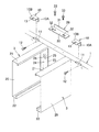
前記支持部材40は、前記受部材39の取付板42に取付ける固定板45の一側縁に、前記端部脚1又は中間脚2の支持アーム7の上面に位置する段状に屈曲した支持板46を折曲形成し、該支持板46には支持ピン47を立設したものである。前記支持部材40の支持板46は、前記端金具29の両突片32,32の間、若しくは中間金具34の突起35,35の間に位置する寸法である。前記支持部材40の固定板45を前記受部材39の取付板42に載せ、該固定板45に形成した通孔48,48に挿通したネジ49,49を前記取付板42の螺孔44.44に螺合して、支持ピン47が立起状態となるように取付ける。   The support member 40 is a support plate bent in a step shape located on the upper surface of the support arm 7 of the end leg 1 or the intermediate leg 2 on one side edge of the fixing plate 45 attached to the attachment plate 42 of the receiving member 39. 46 is bent, and a support pin 47 is erected on the support plate 46. The support plate 46 of the support member 40 has a dimension that is located between the protruding pieces 32 and 32 of the end fitting 29 or between the projections 35 and 35 of the intermediate fitting 34. The fixing plate 45 of the support member 40 is placed on the mounting plate 42 of the receiving member 39, and the screws 49, 49 inserted through the through holes 48 formed in the fixing plate 45 are screw holes 44 .44 of the mounting plate 42. And the support pin 47 is attached so as to be raised.

図11に示すように、前記端部脚1の中央部に支持部材40の支持ピン47が立起し、前記中間脚2の支持アーム7の中央部に2本の支持ピン47,47が立起した状態となる。そして、左右一対の支持ピン47,47を前記机上パネル38の両端に係合して支持するのである。図13及び図14に示すように、前記前記ダクト開口8の上位に位置し、前記ダクトカバー5との間には空間を設けて、該ダクトカバー5の着脱を可能としている。また、前記ダクトカバー5の両端部には、前記支持ピン47を逃がすための切欠部50,50を形成している。   As shown in FIG. 11, a support pin 47 of the support member 40 rises at the center of the end leg 1, and two support pins 47 and 47 stand at the center of the support arm 7 of the intermediate leg 2. It will be in a wake-up state. Then, a pair of left and right support pins 47, 47 are engaged with and supported at both ends of the desktop panel 38. As shown in FIGS. 13 and 14, the duct cover 5 is located above the duct opening 8 and a space is provided between the duct cover 5 and the duct cover 5 can be attached and detached. Further, notches 50 and 50 for allowing the support pins 47 to escape are formed at both ends of the duct cover 5.

1 端部脚、 2 中間脚、
3 ビーム板、 4 天板、
5 ダクトカバー、 6 脚柱、
7 支持アーム、 8 ダクト開口、
9 ダクト空間、 10 取付金具、
10A 垂直片、 10B 水平片、
11 切欠孔、 12 ネジ、
13 取付孔、 14 貫通孔、
15 脚杆、 16 結合片、
17 脚カバー、 18 アジャスター、
19 ダクト開口部、 20 幕板、
21 上側補強縁、 22 下側補強縁、
23 連結部材、 24 取付端板、
25 ダルマ孔、 26 連結ネジ、
27 螺孔、 28 ネジ、
29 端金具、 30 取付板、
31 当止片、 32 突片、
33 ネジ、 34 中間金具、
35 突起、 36 コード受け、
37 係止部、 38 机上パネル、
39 受部材、 40 支持部材、
41 基板、 42 取付板、
43 U字溝、 44 螺孔、
45 固定板、 46 支持板、
47 支持ピン、 48 通孔、
49 ネジ、 50 切欠部。
1 end leg, 2 middle leg,
3 Beam plate, 4 Top plate,
5 Duct cover, 6 pedestal,
7 support arm, 8 duct opening,
9 Duct space, 10 Mounting bracket,
10A vertical piece, 10B horizontal piece,
11 notch holes, 12 screws,
13 mounting holes, 14 through holes,
15 legs, 16 joint pieces,
17 leg covers, 18 adjusters,
19 duct opening, 20 curtain,
21 upper reinforcement edge, 22 lower reinforcement edge,
23 connecting members, 24 mounting end plates,
25 Dharma hole, 26 Connecting screw,
27 screw holes, 28 screws,
29 end fittings, 30 mounting plates,
31 stop pieces, 32 protruding pieces,
33 screws, 34 intermediate brackets,
35 projections, 36 cord receivers,
37 locking part, 38 desktop panel,
39 receiving member, 40 supporting member,
41 substrate, 42 mounting plate,
43 U-groove, 44 screw hole,
45 fixed plate, 46 support plate,
47 support pins, 48 through holes,
49 screws, 50 notches.

Claims (4)

少なくとも両端部に配する端部脚、中間に配し、脚柱と1本の支持アームからなる側面視略T字形の中間脚、前記端部脚と中間脚の間又は中間脚と他の中間脚の間を連結する前後一対のビーム板及び前記端部脚と中間脚の上面に前後に間隔を置いて載置して取付ける天板とを有し、一対の前記ビーム板を前後に間隔を隔てて配置してそれぞれ前記端部脚又は前記中間脚に連結するとともに、前後の天板間のダクト開口の下方に両ビーム板間に形成するダクト空間が位置し、前記ダクト開口にはダクトカバーを着脱可能に装着することを特徴とする組立式デスク。   End legs arranged at at least both ends, arranged in the middle, a substantially T-shaped intermediate leg consisting of a pedestal and one support arm, between the end legs and the intermediate leg or between the intermediate leg and the other intermediate A pair of front and rear beam plates for connecting between the legs, and a top plate mounted on the end leg and the upper surface of the intermediate leg with a space in the front and back, and the pair of beam plates are spaced apart from each other A duct space formed between the two beam plates is located below the duct opening between the front and rear top plates, and is arranged separately from each other and connected to the end leg or the intermediate leg, and the duct opening has a duct cover. An assembly desk that is detachably mounted. 前記ビーム板は、垂直な幕板の上下縁を内方に折曲して上下補強縁を形成するとともに、前記幕板の両端部内側に垂直な取付端板を有する連結部材を固着し、該取付端板を前記端部脚又は前記中間脚の側面上部にネジ止めしてなる請求項1記載の組立式デスク。   The beam plate bends the upper and lower edges of the vertical curtain plate inward to form upper and lower reinforcing edges, and attaches a connecting member having vertical mounting end plates to both inner sides of the curtain plate, The assembly type desk according to claim 1, wherein a mounting end plate is screwed to an upper part of the side surface of the end leg or the intermediate leg. 前記端部脚及び前記中間脚の側面に沿った位置で、前記ビーム板間の上部にわたって受部材を取付け、該受部材に机上パネルの支持部材を取付けるとともに、前記ダクト開口の上位に左右両側の支持部材で机上パネルを支持してなる請求項1又は2記載の組立式デスク。   At a position along the side of the end leg and the intermediate leg, a receiving member is attached over the upper part between the beam plates, and a support member for a desktop panel is attached to the receiving member, and on both the left and right sides above the duct opening. The assembly type desk according to claim 1 or 2, wherein the desktop panel is supported by a support member. 前記受部材は、垂直な基板の上縁を直角に折曲して前記支持部材を取付ける取付板を形成するとともに、前記基板の両側下端部に下方へ開放したU字溝を形成し、前記ビーム板を前記端部脚又は前記中間脚に取付けるネジに両U字溝を係合し、該ビーム板と共締めしてなる請求項3記載の組立式デスク。   The receiving member bends an upper edge of a vertical substrate at a right angle to form a mounting plate for mounting the supporting member, and forms U-shaped grooves opened downward at both lower end portions of the substrate. 4. The assembly type desk according to claim 3, wherein both U-shaped grooves are engaged with a screw for attaching a plate to the end leg or the intermediate leg and fastened together with the beam plate.
JP2013248743A 2013-11-29 2013-11-29 Knockdown desk Pending JP2015104584A (en)

Priority Applications (1)

Application Number Priority Date Filing Date Title
JP2013248743A JP2015104584A (en) 2013-11-29 2013-11-29 Knockdown desk

Applications Claiming Priority (1)

Application Number Priority Date Filing Date Title
JP2013248743A JP2015104584A (en) 2013-11-29 2013-11-29 Knockdown desk

Publications (1)

Publication Number Publication Date
JP2015104584A true JP2015104584A (en) 2015-06-08

Family

ID=53435077

Family Applications (1)

Application Number Title Priority Date Filing Date
JP2013248743A Pending JP2015104584A (en) 2013-11-29 2013-11-29 Knockdown desk

Country Status (1)

Country Link
JP (1) JP2015104584A (en)

Cited By (4)

* Cited by examiner, † Cited by third party
Publication number Priority date Publication date Assignee Title
JP2016214659A (en) * 2015-05-22 2016-12-22 株式会社三共 Game machine
CN109875258A (en) * 2019-04-25 2019-06-14 泰顺县凡有所想文化艺术工作室 A kind of Art Design drawing table
JP2019136308A (en) * 2018-02-09 2019-08-22 株式会社オカムラ Furniture
KR102218709B1 (en) * 2020-10-26 2021-02-24 (주)아모스아인스가구 Multi-person table structure with excellent structural reinforcement and expandability

Citations (5)

* Cited by examiner, † Cited by third party
Publication number Priority date Publication date Assignee Title
JPH08187130A (en) * 1995-01-12 1996-07-23 Okamura Corp Device for planting support column to top panel of desk or the like
JP2007151824A (en) * 2005-12-05 2007-06-21 Itoki Corp Knockdown desk
US20070277710A1 (en) * 2006-06-06 2007-12-06 Gray Daniel G Modular conference table
JP2009148496A (en) * 2007-12-21 2009-07-09 Kokuyo Co Ltd Desk
JP2013111134A (en) * 2011-11-25 2013-06-10 Itoki Corp Connected desk variable in connection mode

Patent Citations (5)

* Cited by examiner, † Cited by third party
Publication number Priority date Publication date Assignee Title
JPH08187130A (en) * 1995-01-12 1996-07-23 Okamura Corp Device for planting support column to top panel of desk or the like
JP2007151824A (en) * 2005-12-05 2007-06-21 Itoki Corp Knockdown desk
US20070277710A1 (en) * 2006-06-06 2007-12-06 Gray Daniel G Modular conference table
JP2009148496A (en) * 2007-12-21 2009-07-09 Kokuyo Co Ltd Desk
JP2013111134A (en) * 2011-11-25 2013-06-10 Itoki Corp Connected desk variable in connection mode

Cited By (5)

* Cited by examiner, † Cited by third party
Publication number Priority date Publication date Assignee Title
JP2016214659A (en) * 2015-05-22 2016-12-22 株式会社三共 Game machine
JP2019136308A (en) * 2018-02-09 2019-08-22 株式会社オカムラ Furniture
JP7093643B2 (en) 2018-02-09 2022-06-30 株式会社オカムラ furniture
CN109875258A (en) * 2019-04-25 2019-06-14 泰顺县凡有所想文化艺术工作室 A kind of Art Design drawing table
KR102218709B1 (en) * 2020-10-26 2021-02-24 (주)아모스아인스가구 Multi-person table structure with excellent structural reinforcement and expandability

Similar Documents

Publication Publication Date Title
JP2015104584A (en) Knockdown desk
JP2006238994A (en) Leg equipment of furniture
JP5516517B2 (en) Desktop panel mounting device
JP5119750B2 (en) Desk leg equipment
JP4749853B2 (en) Assembling desk
JP4274065B2 (en) Mounting device for supporting member
JP2008049182A (en) Knockdown desk
JP2006280797A (en) Desk system
JP6361780B2 (en) Assembling desk
JP6178260B2 (en) Assembling desk
JP6149968B2 (en) Assembling desk
JP5971370B2 (en) Assembling desk
JP6027959B2 (en) Assembling desk
JP5630386B2 (en) Desk divider
JP5275405B2 (en) Desk leg equipment
JP5304014B2 (en) Desktop panel mounting device
JP2008049183A (en) Knockdown desk
JP5907690B2 (en) Assembling desk
JP5923872B2 (en) desk
JPH08308648A (en) Cabinet structure of assembling shelf
JP2011254879A (en) Woody assembling desk
JP6124553B2 (en) desk
JP2011045638A (en) Bookshelf
JP2018015333A (en) Column for shelf board
JP3837616B2 (en) Desk with shelf

Legal Events

Date Code Title Description
A621 Written request for application examination

Free format text: JAPANESE INTERMEDIATE CODE: A621

Effective date: 20161128

A977 Report on retrieval

Free format text: JAPANESE INTERMEDIATE CODE: A971007

Effective date: 20170815

A131 Notification of reasons for refusal

Free format text: JAPANESE INTERMEDIATE CODE: A131

Effective date: 20170818

A521 Request for written amendment filed

Free format text: JAPANESE INTERMEDIATE CODE: A523

Effective date: 20171017

A131 Notification of reasons for refusal

Free format text: JAPANESE INTERMEDIATE CODE: A131

Effective date: 20180327

A02 Decision of refusal

Free format text: JAPANESE INTERMEDIATE CODE: A02

Effective date: 20181002