JP3694015B2 - 内燃機関のスロットル制御装置 - Google Patents
内燃機関のスロットル制御装置 Download PDFInfo
- Publication number
- JP3694015B2 JP3694015B2 JP2004128001A JP2004128001A JP3694015B2 JP 3694015 B2 JP3694015 B2 JP 3694015B2 JP 2004128001 A JP2004128001 A JP 2004128001A JP 2004128001 A JP2004128001 A JP 2004128001A JP 3694015 B2 JP3694015 B2 JP 3694015B2
- Authority
- JP
- Japan
- Prior art keywords
- throttle
- gear
- sensor
- shaft
- brush
- Prior art date
- Legal status (The legal status is an assumption and is not a legal conclusion. Google has not performed a legal analysis and makes no representation as to the accuracy of the status listed.)
- Expired - Lifetime
Links
Images


Landscapes
- Control Of Throttle Valves Provided In The Intake System Or In The Exhaust System (AREA)
Description
を第1の課題とし、組付作業工数を低減させ組付費用を低減させることを第2の課題とする。ギア室のカバーの外側にセンサ室を形成し、センサ部をセンサ室に収容し、センサ室の室壁に呼吸孔を設けることが考えられる。この場合に、ギア室内の摩耗粉が呼吸孔を通ってセンサ室のセンサ部に付着しないようにすることを第3の課題とし、センサ室又はギア室に浸入した水滴で呼吸孔が塞がらないようにすることを第4の課題とする。
本発明は、第1構成において、前記センサ部の前記ブラシを、ブラシレバーの外側に外方に向けて固定したことを第2構成とする。
本発明は、第1及び第2構成において、前記センサ部を収容するセンサ室の室壁に呼吸孔を設けたことを第3構成とする。
本発明は、第1〜第3構成において、中間ギアの固定軸を、スロットルボデー本体及び前記カバーの両方で軸支したことを第4構成とする。
本発明は、第1構成において、センサ基板に埋め込まれた抵抗体から、横方向へ外れた部分に対向した位置に、呼吸孔を配置したことを第5構成とする。
本発明は、第3又は第5構成において、スロットル全閉時のブラシ位置に比べて使用頻度の低いスロットル全開時のブラシ位置から、ブラシの移動範囲の外側方向に外れた部分に対向した位置に呼吸孔を配置したことを第6構成とする。
本発明は、第3構成において、呼吸孔のセンサ室側、ギア室側の一方又は双方に段差部を介して呼吸孔よりも大きい径の補助穴を形成したことを第7構成とする。
請求項2のものは、ブラシをブラシレバーの外側に外方に向けて固定したので、スロットルボデー組付時、ブラシの押圧力を測定するのが容易となり、組付作業工数が低減でき組付費用が低減できる。
請求項4のものは、中間ギアの固定軸の両端を軸支するようにしたので、駆動ギアの駆動力は両軸受で二分され、スロットルボデー本体への圧入部長さが半減できるとともに、固定軸の歪量も半減し、ギア間の摺動量も減少し摺動摩耗粉の発生量が減少するとともにギアの耐久性が向上する。
請求項6のものは、呼吸孔がスロットル全閉時のブラシ位置に比べて使用頻度の低いスロットル全開時のブラシ位置から、ブラシの移動範囲の外側方向に外れた部分に対向した位置に配置されている。従って、ギア室の摩耗粉が呼吸孔を通ってセンサ室に進入したとき、その摩耗粉は抵抗体の不使用部分(ブラシが接触しない部分)又は使用頻度の最も低い部分に付着し、センサ出力信号に対する摩耗粉の影響が軽減される。また、摩耗粉が抵抗体の不使用部分又は最も使用頻度の低い部分に付着することにより、ブラシによる摩耗粉のセンサ基板・抵抗体の全体への飛散を防止することができる。
動するとき、水滴が丸穴に流入して丸穴を塞ぐ可能性がある。丸穴が水滴で塞がれると、センサ室24内の腐食性ガスの排出ができなくなり、腐食性ガスにより抵抗体27及びブラシ18aが腐食される可能性がある。
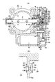
1a:吸気通路
2:スロットルシャフト
2c:外端部
3:スロットルバルブ
6:スロットルギア
12:モータ
13:駆動ギア
14:中間ギア
14a:固定軸
15:カバー
15a:センサ室壁
15b:呼吸孔
17:ダストシール
18:ブラシレバー
18a:ブラシ
22:センサ部
23:ギア室
24:センサ室
27:抵抗体
32:段差部
33:段差部
34:補助穴
35:補助穴
Claims (1)
- 吸気通路を横切り回動可能に設けられたスロットルシャフトと、前記スロットルシャフトと平行に配置されたモータ駆動軸と、前記モータ駆動軸に取り付けられた駆動ギアと、前記スロットルシャフトに取り付けられたスロットルギアと、前記駆動ギアおよび前記スロットルギアに歯合する中間ギアと、前記駆動ギア、前記スロットルギア、および中間ギアを覆うカバーとを備え、前記モータ駆動軸を駆動して前記駆動ギア、前記スロットルギア、および中間ギアを介し、前記スロットルシャフトに固定されたスロットルバルブを開閉させて吸入空気量を制御する内燃機関のスロットル制御装置において、
前記スロットルシャフト外端部には、前記スロットルバルブ側から、前記スロットルギア、前記カバー、および前記スロットルバルブの開度を検出すためにセンサ基板とブラシを備えるセンサ部が順に配置され、
前記カバーには、前記スロットルギアと前記センサ部とを隔離するセンサ室壁と、前記センサ室壁の外周部分に立設された側壁とが一体的に形成されてセンサ室が構成されており、
前記センサ室内に、前記ブラシを前記スロットルシャフトに勘合させたブラシレバーに固着して配置するとともに、前記センサ基板はプレートを介して前記カバーに固定されていることを特徴とする内燃機関のスロットル制御装置。
Priority Applications (1)
| Application Number | Priority Date | Filing Date | Title |
|---|---|---|---|
| JP2004128001A JP3694015B2 (ja) | 1999-08-24 | 2004-04-23 | 内燃機関のスロットル制御装置 |
Applications Claiming Priority (2)
| Application Number | Priority Date | Filing Date | Title |
|---|---|---|---|
| JP27731199 | 1999-08-24 | ||
| JP2004128001A JP3694015B2 (ja) | 1999-08-24 | 2004-04-23 | 内燃機関のスロットル制御装置 |
Related Parent Applications (1)
| Application Number | Title | Priority Date | Filing Date |
|---|---|---|---|
| JP2000042584A Division JP3745573B2 (ja) | 1999-08-24 | 2000-02-21 | 内燃機関のスロットル制御装置 |
Publications (3)
| Publication Number | Publication Date |
|---|---|
| JP2004211713A JP2004211713A (ja) | 2004-07-29 |
| JP2004211713A5 JP2004211713A5 (ja) | 2005-05-26 |
| JP3694015B2 true JP3694015B2 (ja) | 2005-09-14 |
Family
ID=32827243
Family Applications (1)
| Application Number | Title | Priority Date | Filing Date |
|---|---|---|---|
| JP2004128001A Expired - Lifetime JP3694015B2 (ja) | 1999-08-24 | 2004-04-23 | 内燃機関のスロットル制御装置 |
Country Status (1)
| Country | Link |
|---|---|
| JP (1) | JP3694015B2 (ja) |
-
2004
- 2004-04-23 JP JP2004128001A patent/JP3694015B2/ja not_active Expired - Lifetime
Also Published As
| Publication number | Publication date |
|---|---|
| JP2004211713A (ja) | 2004-07-29 |
Similar Documents
| Publication | Publication Date | Title |
|---|---|---|
| JP5147213B2 (ja) | インダクタンス式回転角度検出装置及びそれを備えたモータ駆動式の絞り弁制御装置 | |
| EP1099839B1 (en) | Electronic throttle return mechanism with default and gear backlash control | |
| US6386178B1 (en) | Electronic throttle control mechanism with gear alignment and mesh maintenance system | |
| US6288534B1 (en) | Non-contacting throttle valve position sensor | |
| EP1099841A2 (en) | Electric throttle control system with two-spring failsafe mechanism | |
| EP1024271A2 (en) | Throttle body shaft axial play control | |
| JP2004239266A (ja) | 内燃機関の絞り弁制御装置 | |
| US6349701B1 (en) | Throttle control apparatus for internal combustion engine | |
| US6295968B2 (en) | Throttle apparatus for internal combustion engine | |
| JP3745573B2 (ja) | 内燃機関のスロットル制御装置 | |
| JPH10259740A (ja) | 内燃機関の電子制御式スロットル弁装置 | |
| JP3694013B2 (ja) | 内燃機関のスロットル制御装置 | |
| EP1170486B1 (en) | Electronic throttle control mechanism with integrated modular construction | |
| JP2004132232A (ja) | スロットル制御装置 | |
| JP3694015B2 (ja) | 内燃機関のスロットル制御装置 | |
| US7275557B2 (en) | Method for the production of an electronically controlled butterfly valve with an inductive sensor of “contact-free” type for an internal combustion engine | |
| JP5447266B2 (ja) | 電動アクチュエータ | |
| JP3948016B2 (ja) | スロットル装置 | |
| JP2007278123A (ja) | スロットルバルブ制御装置 | |
| JP3538023B2 (ja) | 回動角検出装置 | |
| JP4307274B2 (ja) | 軸連結部構造 | |
| JP4306529B2 (ja) | 内燃機関の吸気装置 | |
| JP2001227362A (ja) | 内燃機関のスロットル制御装置 | |
| JP4801710B2 (ja) | 内燃機関のスロットル制御装置 | |
| JP4774420B2 (ja) | 内燃機関の吸気絞り弁制御装置 |
Legal Events
| Date | Code | Title | Description |
|---|---|---|---|
| A521 | Written amendment |
Free format text: JAPANESE INTERMEDIATE CODE: A523 Effective date: 20040617 |
|
| A621 | Written request for application examination |
Free format text: JAPANESE INTERMEDIATE CODE: A621 Effective date: 20040617 |
|
| A871 | Explanation of circumstances concerning accelerated examination |
Free format text: JAPANESE INTERMEDIATE CODE: A871 Effective date: 20040617 |
|
| A975 | Report on accelerated examination |
Free format text: JAPANESE INTERMEDIATE CODE: A971005 Effective date: 20040720 |
|
| A131 | Notification of reasons for refusal |
Free format text: JAPANESE INTERMEDIATE CODE: A131 Effective date: 20040824 |
|
| A521 | Written amendment |
Free format text: JAPANESE INTERMEDIATE CODE: A523 Effective date: 20041025 |
|
| A131 | Notification of reasons for refusal |
Free format text: JAPANESE INTERMEDIATE CODE: A131 Effective date: 20050201 |
|
| TRDD | Decision of grant or rejection written | ||
| A01 | Written decision to grant a patent or to grant a registration (utility model) |
Free format text: JAPANESE INTERMEDIATE CODE: A01 Effective date: 20050621 |
|
| A61 | First payment of annual fees (during grant procedure) |
Free format text: JAPANESE INTERMEDIATE CODE: A61 Effective date: 20050622 |
|
| R150 | Certificate of patent or registration of utility model |
Ref document number: 3694015 Country of ref document: JP Free format text: JAPANESE INTERMEDIATE CODE: R150 Free format text: JAPANESE INTERMEDIATE CODE: R150 |
|
| FPAY | Renewal fee payment (event date is renewal date of database) |
Free format text: PAYMENT UNTIL: 20110701 Year of fee payment: 6 |
|
| R250 | Receipt of annual fees |
Free format text: JAPANESE INTERMEDIATE CODE: R250 |
|
| FPAY | Renewal fee payment (event date is renewal date of database) |
Free format text: PAYMENT UNTIL: 20140701 Year of fee payment: 9 |
|
| R250 | Receipt of annual fees |
Free format text: JAPANESE INTERMEDIATE CODE: R250 |
|
| R250 | Receipt of annual fees |
Free format text: JAPANESE INTERMEDIATE CODE: R250 |
|
| R250 | Receipt of annual fees |
Free format text: JAPANESE INTERMEDIATE CODE: R250 |
|
| EXPY | Cancellation because of completion of term |