JP3201784U - Cooling device for computer arithmetic unit - Google Patents
Cooling device for computer arithmetic unit Download PDFInfo
- Publication number
- JP3201784U JP3201784U JP2015600071U JP2015600071U JP3201784U JP 3201784 U JP3201784 U JP 3201784U JP 2015600071 U JP2015600071 U JP 2015600071U JP 2015600071 U JP2015600071 U JP 2015600071U JP 3201784 U JP3201784 U JP 3201784U
- Authority
- JP
- Japan
- Prior art keywords
- cooling device
- flow path
- cpu
- coolant
- known invention
- Prior art date
- Legal status (The legal status is an assumption and is not a legal conclusion. Google has not performed a legal analysis and makes no representation as to the accuracy of the status listed.)
- Expired - Fee Related
Links
Images

Classifications
-
- G—PHYSICS
- G06—COMPUTING; CALCULATING OR COUNTING
- G06F—ELECTRIC DIGITAL DATA PROCESSING
- G06F1/00—Details not covered by groups G06F3/00 - G06F13/00 and G06F21/00
- G06F1/16—Constructional details or arrangements
- G06F1/20—Cooling means
-
- H—ELECTRICITY
- H05—ELECTRIC TECHNIQUES NOT OTHERWISE PROVIDED FOR
- H05K—PRINTED CIRCUITS; CASINGS OR CONSTRUCTIONAL DETAILS OF ELECTRIC APPARATUS; MANUFACTURE OF ASSEMBLAGES OF ELECTRICAL COMPONENTS
- H05K7/00—Constructional details common to different types of electric apparatus
- H05K7/20—Modifications to facilitate cooling, ventilating, or heating
- H05K7/20218—Modifications to facilitate cooling, ventilating, or heating using a liquid coolant without phase change in electronic enclosures
- H05K7/20254—Cold plates transferring heat from heat source to coolant
Landscapes
- Engineering & Computer Science (AREA)
- Theoretical Computer Science (AREA)
- Physics & Mathematics (AREA)
- Microelectronics & Electronic Packaging (AREA)
- Human Computer Interaction (AREA)
- General Engineering & Computer Science (AREA)
- General Physics & Mathematics (AREA)
- Thermal Sciences (AREA)
- Cooling Or The Like Of Electrical Apparatus (AREA)
- Cooling Or The Like Of Semiconductors Or Solid State Devices (AREA)
Abstract
【課題】設計を簡単にし、信頼性を向上し、さらに冷却システムのエネルギー消費を減らすCPU用の冷却装置を提供する。【解決手段】CPU用の冷却装置は、互いに固定された溝付きの2つの平らなプレートを含み、それらが一緒になって少なくとも1つの流路を形成し、流路は密封インサートブロックによって密閉されて内部を冷却液が循環する。CPUで熱を発生する電子部品のための放熱プレートであり、冷却液が循環する流路は流入口及び流出口を有し、それぞれが冷却液を供給及び排出する。【選択図】図1A cooling device for a CPU that simplifies design, improves reliability, and further reduces the energy consumption of a cooling system. A cooling device for a CPU includes two flat plates with grooves fixed to each other, which together form at least one flow path, the flow path being sealed by a sealed insert block. The coolant circulates inside. A heat dissipation plate for an electronic component that generates heat in the CPU, and a flow path through which the coolant circulates has an inlet and an outlet, and each supplies and discharges the coolant. [Selection] Figure 1
Description
この考案は、概して電気工学に関し、特にコンピュータープロセッサの電源供給ユニットを冷却するための装置に関する。 This invention relates generally to electrical engineering, and more particularly to an apparatus for cooling a power supply unit of a computer processor.
2002年10月1日に特許された特許文献1(国際特許分類H05K7/20)は、選択的に配置された放熱フィン、すなわち冷却する電子部品が取り付けられた部分の近くにのみ配置されたフィンを特徴とする電子部品用の液冷放熱体を記載する。 Patent Document 1 (International Patent Classification H05K7 / 20), patented on October 1, 2002, discloses a heat dissipating fin that is selectively disposed, that is, a fin that is disposed only near a portion where an electronic component to be cooled is attached. A liquid-cooled heat dissipating body for electronic parts is described.
上記装置の不都合な点は、追加の部品(フィン、フィン付きのプレート)が冷却液の流れに追加されて冷却液流路の液体抵抗の増加をもたらすために冷却モジュールが取り付けられた部分で局所熱伝達が起こることと、設計費用である。 The disadvantage of the above device is that the additional parts (fins, finned plates) are added locally to the coolant flow to provide increased liquid resistance in the coolant flow path where the cooling module is attached. Heat transfer takes place and design costs.
1991年3月23日発行の特許文献2(国際特許分類H05K7/20)は、ハウジングと、一方の面にしっかりと取り付けられた複数の電子部品を備えた回路基板と、冷却液が循環する流路を形成する積層板からなる放熱体とを含む無線電子モジュールユニットを記載する。そのモジュールでは、回路基板は、構成密度を増加して熱伝達を向上するために、その取り付けのない面で放熱体に接続される。冷却液が循環する流路は、放熱体の内側の層に設けられ、外側の層とそれらの全体の長さに亘って確実に接触し、縦断面において、電子部品の並びに沿って蛇行する形で構成される。 Patent Document 2 (International Patent Classification H05K7 / 20), issued on March 23, 1991, describes a housing, a circuit board having a plurality of electronic components firmly attached to one surface, and a flow through which a coolant circulates. A wireless electronic module unit including a radiator made of a laminated plate forming a path is described. In that module, the circuit board is connected to the heat sink on its non-attached surface in order to increase the configuration density and improve heat transfer. The flow path through which the cooling liquid circulates is provided in the inner layer of the heat dissipating body, is in reliable contact with the outer layer over the entire length thereof, and meanders along the arrangement of the electronic components in the longitudinal section. Consists of.
この発明の不都合な点は、熱が底面の全体から及び電子部品の並びに沿って部分的に放出されることでの、設計の非効率性及び有効性の欠如である。 A disadvantage of this invention is the inefficiency and lack of effectiveness of the design, as heat is partially released from the entire bottom surface and along and along the electronic components.
最も近い技術的な解決は、2006年4月10日に特許された特許文献3(国際特許分類H05K7/20)に記載されたような、電源回路モジュールについての冷却装置であり、それは熱発生回路モジュールの列及び蓋が取り付けられた熱放出基部を含む。冷却装置はまた、冷却剤が循環する流路も含む。この流路は蛇行する形で構成され、熱放出基部は、電子モジュールが取り付けられた場所の下に作られた空洞を含む。空洞に取り付けられた挿入物は、蓋と結合され、冷却剤が循環する流路を形成する。この流路は、相互に接続されて異なる面に配置された直線部及び蛇行区域として設計される。これらの直線部及び蛇行区域のそれぞれは、上記空洞に設置され、そこで流路は直並列の形態で接続され、それに従って冷却液が循環する。電子モジュールを取り付けるために、熱放出基部は、冷却液が循環する流路の蛇行区域に熱交換器を有する。流路内部に設置された熱交換器の部分は、流線型の翼の形状で設計される。その一方で、冷却液の流れが偏向し、かつ冷却液が循環する流路の断面が、対応する電源電子モジュールの動力とつり合う場所において、その流路は回転翼を備える。そして、それぞれの流路での水圧損失を減らすために、直線部の断面は、蛇行区域の断面よりも大きくなっている。さらに、冷却液が循環する少なくとも1つの流路は、冷却液の流れの平衡を保つために、調節装置を備える。 The closest technical solution is a cooling device for a power circuit module, as described in Patent Document 3 (International Patent Classification H05K7 / 20) patented on April 10, 2006, which is a heat generating circuit. It includes a heat release base to which a row of modules and a lid are attached. The cooling device also includes a flow path through which the coolant circulates. The flow path is configured to meander and the heat dissipation base includes a cavity created below where the electronic module is mounted. The insert attached to the cavity is coupled with the lid to form a flow path through which the coolant circulates. This flow path is designed as a straight section and a meandering area connected to each other and arranged on different surfaces. Each of these straight sections and meandering areas is installed in the cavity, where the flow paths are connected in series-parallel fashion and the coolant circulates accordingly. For mounting the electronic module, the heat release base has a heat exchanger in the meandering area of the flow path through which the coolant circulates. The part of the heat exchanger installed inside the flow path is designed in the shape of a streamlined blade. On the other hand, in a place where the flow path of the cooling liquid is deflected and the cross section of the flow path through which the cooling liquid circulates balances the power of the corresponding power supply electronic module, the flow path includes the rotor blades. And in order to reduce the water pressure loss in each flow path, the cross section of a straight part is larger than the cross section of a meandering area. Furthermore, at least one flow path through which the coolant circulates is provided with a regulating device in order to balance the coolant flow.
上記冷却装置は、次の不都合な点を有する。
・最初の熱を発生する電子部品の後での加熱された冷却剤が、次に2番目の熱を発生する電子部品を通る。この工程は、冷却液の更なる使用を必要とする。この不都合な点は、異なる熱発生特性を有した電子部品が、冷却液が循環する経路に沿って使用される場合に特に明らかである。
・個別に各電子部品に対する冷却液の供給量を調節すること及び流路での冷却液の速度を調節することができる構造的な要素がないので、熱交換器の効率を低減する。
The cooling device has the following disadvantages.
The heated coolant after the electronic component that generates the first heat then passes through the electronic component that generates the second heat. This process requires further use of the coolant. This disadvantage is particularly apparent when electronic components having different heat generation characteristics are used along the path through which the coolant circulates.
-The efficiency of the heat exchanger is reduced because there is no structural element that can individually adjust the amount of coolant supplied to each electronic component and adjust the speed of the coolant in the flow path.
提案される技術的な解決の技術的な成果は、CPU(コンピュータの演算装置)用の冷却システムの有効性及び効率性を増大し、その設計を簡単にし、信頼性特性を向上し、さらに冷却システムのエネルギー消費を減らす。 The technical result of the proposed technical solution is to increase the effectiveness and efficiency of the cooling system for CPU (computer computing unit), simplify its design, improve the reliability characteristics, and further cooling Reduce system energy consumption.
技術的な成果は、CPU用の冷却装置が、互いに固定された溝付きの2つの平らなプレートを含み、それらが一緒になって少なくとも1つの流路を形成し、この流路は密封インサートブロックによって密閉されて内部を冷却液が循環することにおいて達成される。これらのプレートは、プレートと接触する、CPUで熱を発生する電子部品のための放熱プレートであり、冷却液が循環する流路は流入口及び流出口を有し、それぞれが冷却液を供給及び排出する。 The technical result is that the cooling device for the CPU comprises two flat plates with grooves fixed to each other, which together form at least one channel, which is a sealed insert block This is achieved by circulating a coolant through the inside. These plates are heat radiating plates for electronic components that contact the plate and generate heat in the CPU, and the flow path through which the cooling liquid circulates has an inlet and an outlet, each supplying the cooling liquid and Discharge.
この場合、CPUの電子部品は、パッド及び/又は様々な熱接点によって平らなプレートに直接接触する。これにより、切断図において、冷却液が循環する流路は、正方形、長方形、円形、又は長円形の形を有することができる。 In this case, the CPU electronics are in direct contact with the flat plate by means of pads and / or various thermal contacts. Thereby, in the cutaway view, the flow path through which the coolant circulates can have a square, rectangular, circular, or oval shape.
溝付きの平らなプレートは、好ましくは互いに締め具又は溶接によって取り付けられる。この場合、それぞれの平らなプレートは、密封インサートブロックが取り付けられる、絶縁された閉じた溝を有する。加えて、互いに取り付けられた2つの平らなプレートは、その設計において、冷却装置を配線ボックスに固定するための固定手段を有することができる。冷却液が循環する流路は、好ましくは1つの連続した形態を有し、それに従って冷却液が循環する。 The grooved flat plates are preferably attached to each other by fasteners or welding. In this case, each flat plate has an insulated closed groove in which a sealing insert block is mounted. In addition, the two flat plates attached to each other can have a fixing means for fixing the cooling device to the wiring box in its design. The flow path through which the cooling liquid circulates preferably has one continuous form, and the cooling liquid circulates accordingly.
さらに、流入口及び流出口は、ホース、管、又はジョンゲスト社の継手のような継手を速やかに接続する手段を有するべきである。 In addition, the inlet and outlet should have a means to quickly connect fittings such as hoses, tubes, or John Guest fittings.
CPU用の冷却システムの作動原理は、電子部品で発生されて得た熱を、冷却液を用いて完全に除去することである。冷却液は、水圧損失を減らしかつコンピュータの熱発生部品の表面温度を均一にするように予め形成された流路に従って、移動する。コンピュータ部品の安定した温度は、全体としてコンピュータの信頼性を増大する。エネルギー節約は、次により達成される。 The operating principle of the cooling system for the CPU is to completely remove the heat generated by the electronic components using the coolant. The coolant moves according to a pre-formed flow path to reduce water pressure loss and to make the surface temperature of the heat generating component of the computer uniform. The stable temperature of the computer parts increases the reliability of the computer as a whole. Energy savings are achieved by:
絶縁された冷却液の温度は、大気冷却を用いることを可能にし、フロン冷却システムなどを完全に止めることができる。 The temperature of the insulated coolant makes it possible to use atmospheric cooling and can completely stop the chlorofluorocarbon cooling system and the like.
同じ得た熱を除去するために必要とされる冷却液の量は、熱容量において等しい空気量よりも4,000倍少ない。これは、異なる状況間での熱容量の違いによるものである。 The amount of coolant needed to remove the same heat gained is 4,000 times less than an equal amount of air in heat capacity. This is due to the difference in heat capacity between different situations.
上記で提案された冷却システムは、CPUで熱を発生する電子部品に直接又は別の熱接点を介して接続されるように形成された1枚以上の冷却プレートを含む。電子部品の中でも特に、本考案の冷却システムは、2.5インチディスク又は3.5インチディスクを冷却するために使用される。冷却プレートはまた、ハウジング部品としても用いられて、CPUの構造的完全性を強化する。 The cooling system proposed above includes one or more cooling plates configured to be connected directly or via another thermal contact to an electronic component that generates heat in the CPU. Among other electronic components, the cooling system of the present invention is used to cool 2.5 inch disks or 3.5 inch disks. The cooling plate is also used as a housing part to enhance the structural integrity of the CPU.
冷却液は、少なくとも1つの流路で冷却プレートの内側を循環する。それにより、冷却液は、主に接触伝熱によって電子部品の表面から得た熱を除去する。CPUの冷却システムの流入及び流出は、外部の液体冷却システムに接続される。 The cooling liquid circulates inside the cooling plate in at least one flow path. Thereby, the cooling liquid removes heat obtained from the surface of the electronic component mainly by contact heat transfer. The inflow and outflow of the CPU cooling system is connected to an external liquid cooling system.
CPU用の冷却システムの冷却装置は、冷却液が循環する流路を含む2つの部品と、密封インサートブロックと、CPUで熱を発生する電子部品と直接又は様々な熱接点を介して接触する熱放出基部とを含む。標準的なメモリモジュールを冷却するために、熱交換器は溝について使用され、メモリモジュールは熱交換器の熱接点を用いて内側に設置されて固定される。熱交換器は、CPUの冷却装置に取り付けられて、メモリモジュールから熱交換器を通っての冷却装置への熱伝達が、接触作用を介して実行される。 The cooling system of the cooling system for the CPU includes two parts including a flow path through which a coolant circulates, a sealed insert block, and electronic components that generate heat in the CPU, either directly or through various heat contacts. A release base. In order to cool standard memory modules, heat exchangers are used for the grooves, and the memory modules are installed and secured inside using heat exchanger hot contacts. The heat exchanger is attached to the cooling device of the CPU, and heat transfer from the memory module to the cooling device through the heat exchanger is performed via a contact action.
冷却液が循環する流路は、長方形の溝の形でCPU用の冷却装置の本体に作られ、一貫したパターンを有し、それに従って冷却液が循環する。冷却装置の上記部品(一方又は両方)は、密封インサートブロックの取り付けのための2つの分離した閉じた溝を有し、冷却装置を配線ボックス内に取り付けるための締め具を有する。 The flow path through which the coolant circulates is formed in the body of the cooling device for the CPU in the form of a rectangular groove, has a consistent pattern, and the coolant circulates accordingly. The part (one or both) of the cooling device has two separate closed grooves for mounting the sealed insert block and has fasteners for mounting the cooling device in the wiring box.
本考案を、以下で図を参照して説明する。
冷却システムの冷却装置は、様々な公知の手段で冷却されるCPUにも取り付けられることができる。標準的なメモリモジュール及びディスクを備えた示されるCPU用の冷却装置は、冷却液が循環する流路を含む2つの部品と、密封インサートブロックと、CPUで熱を発生する電子部品と接触する熱接点が取り付けられた熱放出基部とを含む。CPUのための冷却液が循環する流路は、長方形の溝の形で上記部品(一方又は両方)の本体に作られ、一貫したパターンを有し、それに従って冷却液が循環する。冷却装置の上記部品(一方又は両方)は、密封インサートブロックの取り付けのための2つの分離した閉じた経路を有し、冷却装置を配線ボックスに取り付けるための締め具を有する。メモリモジュールが、熱交換器の熱接点を用いて内側に設置されて取り付けられ、溝での熱交換器が、標準的なメモリモジュールを冷却するために使用される。熱交換器自体は、CPUの冷却装置に取り付けられ、メモリモジュールから熱交換器を通っての冷却装置への熱伝達は、接触作用を介して実行される。電子部品の中でも特に、プレートは2つの2.5インチディスク又は3.5インチディスクを冷却するために使用される。
The present invention will be described below with reference to the drawings.
The cooling device of the cooling system can also be attached to a CPU that is cooled by various known means. The cooling device for the CPU shown with a standard memory module and disk comprises two parts including a flow path through which the coolant circulates, a sealed insert block, and heat in contact with the electronic components that generate heat in the CPU. And a heat release base to which contacts are attached. The flow path through which the coolant for the CPU circulates is made in the body of the part (one or both) in the form of a rectangular groove, has a consistent pattern, and the coolant circulates accordingly. The part (one or both) of the cooling device has two separate closed paths for the mounting of the sealing insert block and has fasteners for mounting the cooling device to the wiring box. A memory module is installed and mounted inside using heat exchanger hot contacts, and a heat exchanger in the groove is used to cool the standard memory module. The heat exchanger itself is attached to the cooling device of the CPU, and heat transfer from the memory module through the heat exchanger to the cooling device is performed via contact action. Among other electronic components, the plate is used to cool two 2.5 inch disks or 3.5 inch disks.
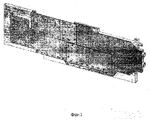
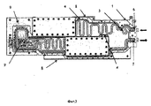
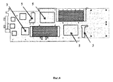
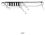
CPU用の冷却装置は、2つの部品(1)、(2)(図2、3、5)をフライス加工することによって設計され、これらは冷却液が循環する流路(3)を含む。流路の密閉性を確実なものにするために、弾性材料で作られたリング状の密封インサートブロックが溝(4)に配置される(図2)。CPUで熱を発生する電子部品(図4の位置5)と接触する部品(1)の外面に接して熱交換器がある。部品(1)の側面には、冷却液が循環しかつ密封インサートブロック(4)によって部品(2)で閉鎖される流路3に接続された、冷却液の供給及び排出のための流入口(6)及び流出口(7)がある。部品(1)(図2)は、配線ボックス(8)内に冷却装置を設置するためにガイド部材を含む。電子部品の中でも特に、プレートは2.5インチディスク又は3.5インチディスクを冷却するために使用される(図2の位置9)。図5は、標準的なメモリモジュール(図5の位置10)を冷却するための実装された熱交換器を備えた、2つの部品(1)、(2)を含むCPUの冷却装置の断面を示す。熱交換器は、熱接点(11)を用いて、冷却装置に取り付けられる。
The cooling device for the CPU is designed by milling two parts (1), (2) (FIGS. 2, 3, 5), which include a flow path (3) through which the coolant circulates. In order to ensure the sealing of the channel, a ring-shaped sealing insert block made of an elastic material is arranged in the groove (4) (FIG. 2). There is a heat exchanger in contact with the outer surface of the component (1) that contacts the electronic component (position 5 in FIG. 4) that generates heat in the CPU. On the side of the part (1) is an inlet (for cooling liquid supply and discharge) connected to the
CPU用の冷却装置は、次のように作用する。部品(1)の流入口(6)を通って、冷却液が循環する流路(3)に冷却液が供給される。流路(3)は、部品(1)、(2)を組み合わせて形成される。冷却液は、冷却液が循環する流路を通って矢印の方向に移動する。流路は、長方形の溝の形で上記部品の本体に作られ、冷却液が循環するパターンを有し、冷却液の流れを最適化して冷却装置の効率性及び有効性を向上することができる。 The cooling device for CPU operates as follows. The coolant is supplied to the flow path (3) through which the coolant circulates through the inlet (6) of the component (1). The flow path (3) is formed by combining the parts (1) and (2). The coolant moves in the direction of the arrow through the flow path through which the coolant circulates. The flow path is formed in the body of the above part in the shape of a rectangular groove and has a pattern in which the cooling liquid circulates, and the flow of the cooling liquid can be optimized to improve the efficiency and effectiveness of the cooling device. .
流路が2つの部品の間にあるこのような設計は、高速の液体通路を提供する最適な断面形状を作ること、効率性を増大すること、及び不必要な密閉ガスケットの使用を避けて冷却装置の設計を簡単にすることができる。メモリモジュールが、熱交換器の熱接点を用いて設置されて取り付けられ、溝での熱交換器が、標準的なメモリモジュールから得た熱を除去する。熱交換器自体は、CPUの冷却装置に取り付けられ、メモリモジュールから熱交換器を通っての冷却装置への熱伝達が、接触作用を介して実行される。 Such a design where the flow path is between the two parts creates an optimal cross-sectional shape that provides a high-speed liquid passage, increases efficiency, and avoids the use of unnecessary sealing gaskets. The design of the device can be simplified. A memory module is installed and mounted using the heat contact of the heat exchanger, and the heat exchanger in the groove removes the heat gained from the standard memory module. The heat exchanger itself is attached to the cooling device of the CPU, and heat transfer from the memory module to the cooling device through the heat exchanger is performed via a contact action.
CPU用の冷却装置の一般的な態様が上述されたが、上記で示された情報に基づいて、例えばプレートがCPUに対して違う方法で設置されるなど、様々な冷却装置が設計されることができることは、この特定の対象を専門とする当業者にとって明らかである。 The general aspects of the cooling device for the CPU have been described above. Based on the information shown above, various cooling devices are designed, for example, the plates are installed differently with respect to the CPU. It will be apparent to one skilled in the art who specializes in this particular subject.
1 冷却装置の部品
2 冷却装置の部品
3 流路
4 溝
5 CPUで熱を発生する電子部品の位置
6 流入口
7 流出口
8 配線ボックス
9 2.5インチディスク又は3.5インチディスクを冷却する位置
10 標準的なメモリモジュール
11 熱接点
DESCRIPTION OF
Claims (9)
Applications Claiming Priority (3)
| Application Number | Priority Date | Filing Date | Title |
|---|---|---|---|
| RU2012145747 | 2012-10-26 | ||
| RU2012145747 | 2012-10-26 | ||
| PCT/RU2013/000087 WO2014065696A1 (en) | 2012-10-26 | 2013-02-07 | Computer module cooler |
Publications (1)
| Publication Number | Publication Date |
|---|---|
| JP3201784U true JP3201784U (en) | 2016-01-07 |
Family
ID=50544957
Family Applications (1)
| Application Number | Title | Priority Date | Filing Date |
|---|---|---|---|
| JP2015600071U Expired - Fee Related JP3201784U (en) | 2012-10-26 | 2013-02-07 | Cooling device for computer arithmetic unit |
Country Status (6)
| Country | Link |
|---|---|
| US (1) | US9335800B2 (en) |
| JP (1) | JP3201784U (en) |
| KR (1) | KR20150002626U (en) |
| CN (1) | CN204189458U (en) |
| DE (1) | DE202013011767U1 (en) |
| WO (1) | WO2014065696A1 (en) |
Families Citing this family (6)
| Publication number | Priority date | Publication date | Assignee | Title |
|---|---|---|---|---|
| BR112016002693A2 (en) * | 2013-08-07 | 2017-08-01 | Abb Spa | cooling device for an electrical device, electrical or electronic device, switch and switchboard |
| KR102570579B1 (en) * | 2018-07-13 | 2023-08-24 | 엘지전자 주식회사 | Refrigerator |
| US10840167B2 (en) | 2018-11-19 | 2020-11-17 | Advanced Micro Devices, Inc. | Integrated heat spreader with configurable heat fins |
| EP3879382B1 (en) * | 2020-03-13 | 2022-11-16 | EKWB d.o.o. | Cooling device for a computer module |
| WO2022188036A1 (en) * | 2021-03-09 | 2022-09-15 | 深圳市大疆创新科技有限公司 | Vehicle controller and vehicle |
| CN116507097B (en) * | 2023-06-25 | 2024-05-28 | 盐城工学院 | Motor controller and automation equipment |
Family Cites Families (20)
| Publication number | Priority date | Publication date | Assignee | Title |
|---|---|---|---|---|
| US4551787A (en) * | 1983-02-07 | 1985-11-05 | Sperry Corporation | Apparatus for use in cooling integrated circuit chips |
| US5363659A (en) * | 1987-07-31 | 1994-11-15 | Heat And Control, Inc. | Ice making apparatus |
| SU1637051A1 (en) * | 1989-04-26 | 1991-03-23 | Предприятие П/Я В-2969 | Radioelectronic equipment unit module |
| SU1762429A1 (en) * | 1990-12-25 | 1992-09-15 | Конструкторское Бюро Электроприборостроения | Electronic unit module |
| US5159529A (en) * | 1991-05-15 | 1992-10-27 | International Business Machines Corporation | Composite liquid cooled plate for electronic equipment |
| RU2088059C1 (en) * | 1995-05-10 | 1997-08-20 | Центральный научно-исследовательский институт "Электроприбор" | Radio electron equipment cabinet |
| IT1297593B1 (en) | 1997-08-08 | 1999-12-17 | Itelco S P A | LIQUID-COOLED DISPENSER FOR ELECTRONIC COMPONENTS, EQUIPPED WITH DISSIPATOR FINS ARRANGED IN A SELECTIVE MANNER |
| US6988534B2 (en) * | 2002-11-01 | 2006-01-24 | Cooligy, Inc. | Method and apparatus for flexible fluid delivery for cooling desired hot spots in a heat producing device |
| WO2005002307A1 (en) * | 2003-06-27 | 2005-01-06 | Nec Corporation | Cooler for electronic equipment |
| DK200301577A (en) * | 2003-10-27 | 2005-04-28 | Danfoss Silicon Power Gmbh | Flow distribution unit and cooling unit |
| US20060021745A1 (en) * | 2004-07-28 | 2006-02-02 | Karl Fritze | Heat exchanger and fluid reservoir |
| RU2273970C1 (en) | 2004-09-06 | 2006-04-10 | Сибирский филиал Федерального государственного унитарного предприятия Всероссийский научно-исследовательский и конструкторско-технологический институт подвижного состава Министерства путей сообщения Российской Федерации | Cooling device for electronic power modules |
| US7298618B2 (en) * | 2005-10-25 | 2007-11-20 | International Business Machines Corporation | Cooling apparatuses and methods employing discrete cold plates compliantly coupled between a common manifold and electronics components of an assembly to be cooled |
| ATE513456T1 (en) * | 2006-08-10 | 2011-07-15 | Continental Automotive Gmbh | ELECTRONIC UNIT WITH SEALED COOLANT PASSAGE |
| US7764494B2 (en) * | 2007-11-20 | 2010-07-27 | Basic Electronics, Inc. | Liquid cooled module |
| IL195939A (en) * | 2008-01-02 | 2012-07-31 | P T H Engineering Ltd | Pipe fitting for a groovable pipe and a method for forming same |
| PL2294496T3 (en) * | 2008-05-21 | 2017-10-31 | Asetek As | Graphics card thermal interposer |
| US20120087088A1 (en) * | 2008-08-05 | 2012-04-12 | Pipeline Micro, Inc. | Microscale heat transfer systems |
| US8427832B2 (en) * | 2011-01-05 | 2013-04-23 | Toyota Motor Engineering & Manufacturing North America, Inc. | Cold plate assemblies and power electronics modules |
| US20140049908A1 (en) * | 2012-08-20 | 2014-02-20 | André Sloth Eriksen | Thermal management system |
-
2013
- 2013-02-07 US US14/238,939 patent/US9335800B2/en active Active
- 2013-02-07 WO PCT/RU2013/000087 patent/WO2014065696A1/en active Application Filing
- 2013-02-07 JP JP2015600071U patent/JP3201784U/en not_active Expired - Fee Related
- 2013-02-07 KR KR2020147000020U patent/KR20150002626U/en not_active Application Discontinuation
- 2013-02-07 CN CN201390000136.1U patent/CN204189458U/en not_active Expired - Fee Related
- 2013-02-07 DE DE202013011767.2U patent/DE202013011767U1/en not_active Expired - Lifetime
Also Published As
| Publication number | Publication date |
|---|---|
| KR20150002626U (en) | 2015-07-06 |
| US20150234438A1 (en) | 2015-08-20 |
| US9335800B2 (en) | 2016-05-10 |
| WO2014065696A1 (en) | 2014-05-01 |
| DE202013011767U1 (en) | 2015-01-30 |
| CN204189458U (en) | 2015-03-04 |
Similar Documents
| Publication | Publication Date | Title |
|---|---|---|
| JP3201784U (en) | Cooling device for computer arithmetic unit | |
| JP5024600B2 (en) | Heating element cooling structure and driving device having the structure | |
| KR101454326B1 (en) | Pump for water cooler | |
| JP4551261B2 (en) | Cooling jacket | |
| JP6534873B2 (en) | Liquid cooling system | |
| JP6546521B2 (en) | Liquid cooling system | |
| TW200529733A (en) | Liquid cooling system and electronic apparatus having the same therein | |
| CN108766946B (en) | Liquid cooling heat abstractor and motor controller | |
| CN109982544B (en) | Liquid cooling radiator | |
| JP6085196B2 (en) | Double-sided mounting cooling plate | |
| CN106774740A (en) | Board-like water-cooled graphic card radiator | |
| JP6322930B2 (en) | Heat receiver, cooling unit, electronic equipment | |
| JP4697171B2 (en) | COOLING DEVICE AND ELECTRONIC DEVICE HAVING THE SAME | |
| JP4867411B2 (en) | Cooling device for electronic equipment | |
| CN108489303A (en) | A kind of heat sink arrangement with thermal insulation layer | |
| CN206657307U (en) | Board-like water cooling graphic card radiator | |
| RU125757U1 (en) | COOLER OF COMPUTER COMPUTER MODULES | |
| JP2019114682A (en) | Liquid-cooled cooler | |
| JP2008300447A (en) | Heat radiation device | |
| JP2010210202A (en) | Heat exchange body | |
| JP2005011928A (en) | Liquid-cooling circulation system | |
| CN211607189U (en) | Liquid cooling device with pumping structure | |
| JP2019079908A (en) | Cooling device and semiconductor module including the same | |
| JP4517962B2 (en) | Cooling device for electronic equipment | |
| TW202239302A (en) | Liquid-cooling heat dissipation structure |
Legal Events
| Date | Code | Title | Description |
|---|---|---|---|
| A521 | Request for written amendment filed |
Free format text: JAPANESE INTERMEDIATE CODE: A523 Effective date: 20151013 |
|
| R150 | Certificate of patent or registration of utility model |
Ref document number: 3201784 Country of ref document: JP Free format text: JAPANESE INTERMEDIATE CODE: R150 |
|
| LAPS | Cancellation because of no payment of annual fees |