JP2023118219A - Elastic sheet for holding workpiece, sheet holding ring, workpiece holding device, workpiece holding method, and workpiece delivery method - Google Patents
Elastic sheet for holding workpiece, sheet holding ring, workpiece holding device, workpiece holding method, and workpiece delivery method Download PDFInfo
- Publication number
- JP2023118219A JP2023118219A JP2022021051A JP2022021051A JP2023118219A JP 2023118219 A JP2023118219 A JP 2023118219A JP 2022021051 A JP2022021051 A JP 2022021051A JP 2022021051 A JP2022021051 A JP 2022021051A JP 2023118219 A JP2023118219 A JP 2023118219A
- Authority
- JP
- Japan
- Prior art keywords
- elastic sheet
- workpiece
- ring
- hole
- work
- Prior art date
- Legal status (The legal status is an assumption and is not a legal conclusion. Google has not performed a legal analysis and makes no representation as to the accuracy of the status listed.)
- Pending
Links
- 238000000034 method Methods 0.000 title claims abstract description 21
- 238000002716 delivery method Methods 0.000 title 1
- 230000007246 mechanism Effects 0.000 claims abstract description 35
- 239000000463 material Substances 0.000 claims abstract description 4
- 230000036316 preload Effects 0.000 claims description 10
- 239000000696 magnetic material Substances 0.000 claims description 9
- 238000003825 pressing Methods 0.000 claims description 7
- 238000007599 discharging Methods 0.000 claims description 5
- 230000008602 contraction Effects 0.000 claims description 3
- 230000000717 retained effect Effects 0.000 claims description 2
- 239000011148 porous material Substances 0.000 claims 2
- 238000011084 recovery Methods 0.000 description 9
- 230000000873 masking effect Effects 0.000 description 5
- 230000002093 peripheral effect Effects 0.000 description 5
- 230000008859 change Effects 0.000 description 4
- 239000002184 metal Substances 0.000 description 4
- 229910052751 metal Inorganic materials 0.000 description 4
- 239000003985 ceramic capacitor Substances 0.000 description 3
- PXHVJJICTQNCMI-UHFFFAOYSA-N Nickel Chemical compound [Ni] PXHVJJICTQNCMI-UHFFFAOYSA-N 0.000 description 2
- 230000015572 biosynthetic process Effects 0.000 description 2
- 238000010586 diagram Methods 0.000 description 2
- NJPPVKZQTLUDBO-UHFFFAOYSA-N novaluron Chemical compound C1=C(Cl)C(OC(F)(F)C(OC(F)(F)F)F)=CC=C1NC(=O)NC(=O)C1=C(F)C=CC=C1F NJPPVKZQTLUDBO-UHFFFAOYSA-N 0.000 description 2
- 230000000630 rising effect Effects 0.000 description 2
- 229920002379 silicone rubber Polymers 0.000 description 2
- 239000000853 adhesive Substances 0.000 description 1
- 230000001070 adhesive effect Effects 0.000 description 1
- 238000005452 bending Methods 0.000 description 1
- 230000008901 benefit Effects 0.000 description 1
- 230000006866 deterioration Effects 0.000 description 1
- 230000000694 effects Effects 0.000 description 1
- 230000003028 elevating effect Effects 0.000 description 1
- 239000007788 liquid Substances 0.000 description 1
- 238000012986 modification Methods 0.000 description 1
- 230000004048 modification Effects 0.000 description 1
- 238000000465 moulding Methods 0.000 description 1
- 229910052759 nickel Inorganic materials 0.000 description 1
- 230000035515 penetration Effects 0.000 description 1
- 230000008569 process Effects 0.000 description 1
- 238000003672 processing method Methods 0.000 description 1
- 238000004080 punching Methods 0.000 description 1
- 238000000926 separation method Methods 0.000 description 1
- 238000004544 sputter deposition Methods 0.000 description 1
- 238000007740 vapor deposition Methods 0.000 description 1
Images


Classifications
-
- B—PERFORMING OPERATIONS; TRANSPORTING
- B23—MACHINE TOOLS; METAL-WORKING NOT OTHERWISE PROVIDED FOR
- B23Q—DETAILS, COMPONENTS, OR ACCESSORIES FOR MACHINE TOOLS, e.g. ARRANGEMENTS FOR COPYING OR CONTROLLING; MACHINE TOOLS IN GENERAL CHARACTERISED BY THE CONSTRUCTION OF PARTICULAR DETAILS OR COMPONENTS; COMBINATIONS OR ASSOCIATIONS OF METAL-WORKING MACHINES, NOT DIRECTED TO A PARTICULAR RESULT
- B23Q3/00—Devices holding, supporting, or positioning work or tools, of a kind normally removable from the machine
- B23Q3/02—Devices holding, supporting, or positioning work or tools, of a kind normally removable from the machine for mounting on a work-table, tool-slide, or analogous part
- B23Q3/06—Work-clamping means
-
- H—ELECTRICITY
- H01—ELECTRIC ELEMENTS
- H01G—CAPACITORS; CAPACITORS, RECTIFIERS, DETECTORS, SWITCHING DEVICES OR LIGHT-SENSITIVE DEVICES, OF THE ELECTROLYTIC TYPE
- H01G13/00—Apparatus specially adapted for manufacturing capacitors; Processes specially adapted for manufacturing capacitors not provided for in groups H01G4/00 - H01G11/00
-
- H—ELECTRICITY
- H01—ELECTRIC ELEMENTS
- H01G—CAPACITORS; CAPACITORS, RECTIFIERS, DETECTORS, SWITCHING DEVICES OR LIGHT-SENSITIVE DEVICES, OF THE ELECTROLYTIC TYPE
- H01G4/00—Fixed capacitors; Processes of their manufacture
- H01G4/30—Stacked capacitors
Abstract
Description
本発明は、セラミックコンデンサーなど電子機器に使用される小さなチップ部品の保持に適するワーク保持用の弾性シート、シート保持環、ワークの保持装置、およびワークの保持方法、およびワークの排出方法に関する。 The present invention relates to an elastic sheet for holding a work, a sheet holding ring, a work holding device, a work holding method, and a work discharging method suitable for holding small chip parts used in electronic devices such as ceramic capacitors.
電子部品に代表される小さなチップ部品(ワーク)は、電子機器の高性能化と共に更なる小型化が求められており、これに伴い、例えば、チップの端に外部電極を形成する加工などに際してワークの保持が困難になってきている。
この様な小さなワークを保持する技術としては、例えば、小さな孔をあけた金属板を複数枚重ね合わせ、これらの金属板を対角線方向に移動することにより貫通する孔の大きさを調整し、調整した各孔内にワークであるチップ部品を保持してマスキングした状態でチップの端部に外部電極を形成する方法が提案されている。
Small chip parts (workpieces) typified by electronic parts are required to be further miniaturized as the performance of electronic equipment is improved. is becoming difficult to maintain.
As a technique for holding such a small workpiece, for example, a plurality of metal plates with small holes are superimposed and the size of the through hole is adjusted by moving these metal plates in the diagonal direction. A method has been proposed in which a chip component, which is a work, is held in each hole and masked, and external electrodes are formed at the end of the chip.
前記したチップ部品電極形成方法ではマスキングした金属板の板厚に相当する段差が外部端子に生じてしまい、また、金属板をずらすことによりチップの大きさに対応させているのでチップに対する密着度合いが不十分となって隙間ができてしまい、設計通りのマスキングができない。さらにはチップの形状にも制限されてしまい、例えば円柱状のワークに適用できない。 In the method of forming the electrodes of the chip component described above, a step corresponding to the thickness of the masked metal plate is formed on the external terminal. If it becomes insufficient, a gap will be created, and masking as designed cannot be performed. Furthermore, the shape of the chip is also limited, and it cannot be applied to, for example, cylindrical workpieces.
本発明は前記した不都合に鑑み提案されたもので、その目的は、小さなワークに対しても段差もなく十分な密着性を確保するなどして工作工程において容易に取り扱うことができるワーク保持用の弾性シート、シート保持環、ワークの保持装置、ワークの保持方法、およびワークの排出方法を提供しようとするものである。 SUMMARY OF THE INVENTION The present invention has been proposed in view of the above-mentioned problems. An object of the present invention is to provide an elastic sheet, a sheet retaining ring, a work retaining device, a work retaining method, and a work discharging method.
本発明は前記した目的を達成するために提案されたものであり、請求項1に記載のものは、弾性を有するシート材からなり、加工対象物となるワークの太さよりも小さな貫通孔を有し、張力を加えて前記貫通孔を拡張した状態で当該貫通孔内にワークを入れ、この状態で前記張力を緩めることにより貫通孔を収縮して当該貫通孔内にワークを保持することを特徴とするワーク保持用の弾性シートである。
SUMMARY OF THE INVENTION The present invention has been proposed to achieve the above-mentioned objects, and according to
請求項2に記載のものは、張力を緩めた状態での厚さがワークの長さよりも小さく設定され、張力を緩めて貫通孔内にワークを保持した状態でワークの端部が貫通孔から露出するように構成されたことを特徴とする請求項1に記載のワーク保持用の弾性シートである。
According to
請求項3に記載のものは、前記請求項1または請求項2に記載のワーク保持用の弾性シートを広げた状態で装着保持するためのリング状のシート保持環であって、
該シート保持環は、円形の開口を有し、該開口の外側に、弾性シートを保持する保持部を備えたリング本体と、該リング本体に保持した弾性シートに初期張力を加えるプリロード用リングとから構成され、
プリロード用リングは、前記リング本体に取り付ける取付部を有し、該取付部から起立してリング本体の開口の内周に沿って入り込むリング状の起立壁を有し、
該起立壁は、前記リング本体に取り付けた状態で、前記保持部により保持した弾性シートに当接して当該弾性シートに対して初期張力を付与し得る起立高さに設定されていることを特徴とするシート保持環である。
According to
The sheet retaining ring has a circular opening, a ring body provided with a retaining portion for retaining an elastic sheet outside the opening, and a preloading ring that applies initial tension to the elastic sheet retained in the ring body. consists of
The preload ring has an attachment portion attached to the ring body, and has a ring-shaped standing wall that rises from the attachment portion and enters along the inner circumference of the opening of the ring body,
The standing wall is set to a standing height that can contact the elastic sheet held by the holding part and apply initial tension to the elastic sheet in a state of being attached to the ring body. It is a seat retaining ring that
請求項4に記載のものは、前記リング本体が、同心円状の開口をそれぞれ有する第1のリングと、該第1のリングに重ね合わせる第2のリングと、からなり、上リングと下リングとで挟み付けた弾性シートを保持する保持部を備えたものである。
According to
請求項5に記載のものは、前記請求項1または請求項2に記載のワーク保持用の弾性シートと、
前記ワーク保持用の弾性シートを広げた状態で装着保持するためのリング状のシート保持環と、
該シート保持環に装着した前記弾性シートに対して面方向に張力を加える張力付加機構と、
を備え、
前記張力付加機構により弾性シートに張力を加えて前記貫通孔を拡張した状態で当該貫通孔内にワークを入れ、この状態で張力付加機構の張力付加を緩めることにより貫通孔を収縮して当該貫通孔内にワークを保持することを特徴とするワークの保持装置である。
According to
a ring-shaped sheet holding ring for mounting and holding the elastic sheet for holding the workpiece in a spread state;
a tension applying mechanism that applies tension in a plane direction to the elastic sheet attached to the sheet retaining ring;
with
A workpiece is inserted into the through-hole in a state in which the through-hole is expanded by applying tension to the elastic sheet by the tension-applying mechanism. This work holding device is characterized by holding a work in a hole.
請求項6に記載のものは、前記張力付加機構は、前記シート保持環を取り付けるシート側テーブルと、該シート側テーブルに取り付けたシート保持環の軸方向に相対的に移動する突入側テーブルとからなり、
前記シート側テーブルは、所定位置に載置したシート保持環をクランプするクランプ具と、クランプしたシート保持環の開口に対応する部分に突入開口部を有し、
前記突入側テーブルは、先端部分がシート保持環の開口よりも小径であって、シート保持環の開口に突入する状態で弾性シートに当たるショルダー部分に複数の回転体を有し、各回転体の回転中心軸が前記ショルダー部分の円周の接線方向に対して平行に配置されている、
ことを特徴とする請求項5に記載のワークの保持装置である。
According to a sixth aspect of the present invention, the tension applying mechanism comprises a seat-side table on which the seat-retaining ring is attached, and a thrust-side table that moves relatively in the axial direction of the seat-retaining ring attached to the seat-side table. become,
The seat-side table has a clamping tool for clamping the seat-holding ring placed at a predetermined position, and a plunge opening in a portion corresponding to the opening of the clamped seat-holding ring,
The entry-side table has a front end portion smaller in diameter than the opening of the seat retaining ring, and has a plurality of rotating bodies in a shoulder portion that contacts the elastic sheet in a state of entering the opening of the seat retaining ring. the central axis is arranged parallel to the tangential direction of the circumference of the shoulder portion;
The workpiece holding device according to
請求項7に記載のものは、 前記回転体よりも弾性シート側に突出した高さ基準リングを、回転体の列の内側に配置したことを特徴とする請求項6に記載のワークの保持装置である。 According to claim 7, the work holding device according to claim 6, wherein the height reference ring protruding toward the elastic sheet from the rotating body is arranged inside the row of rotating bodies. is.
請求項8に記載のものは、前記張力付加機構により弾性シートに張力を加えて前記貫通孔を拡張した状態において、拡張された前記貫通孔内にワークを供給するフィーダー機構を備えたことを特徴とする請求項5から7のいずれかに記載のワークの保持装置である。
According to an eighth aspect of the present invention, a feeder mechanism is provided to feed a workpiece into the expanded through-hole in a state in which the tension applying mechanism applies tension to the elastic sheet to expand the through-hole. The workpiece holding device according to any one of
請求項9に記載のものは、前記張力付加機構により弾性シートに張力を加えて前記貫通孔を拡張した状態において前記弾性シートに振動を与える振動付加機構と、弾性シート上に複数のワークを供給するワーク供給機構と、を備えたことを特徴とする請求項5から7のいずれかに記載のワークの保持装置である。
According to a ninth aspect of the present invention, a vibration applying mechanism applies tension to the elastic sheet by the tension applying mechanism to vibrate the elastic sheet in a state in which the through hole is expanded, and a plurality of works are supplied onto the elastic sheet. 8. The workpiece holding device according to any one of
請求項10に記載のものは、前記突入側テーブルは、弾性シートの突入側の面に臨ませて着座用受台を備えたことを特徴とする請求項5から請求項9のいずれかに記載のワークの保持装置である。 According to claim 10, the entry-side table is provided with a seating base facing the entry-side surface of the elastic sheet. is a work holding device.
請求項11に記載のものは、着座用受台の着座面の裏側に磁力発生手段を設け、磁性体を含むワークに磁力を作用させて弾性シートの貫通孔に誘導可能としたことを特徴とする請求項10に記載のワークの保持装置である。 According to the eleventh aspect of the present invention, a magnetic force generating means is provided on the back side of the seating surface of the seating pedestal so that a magnetic force can be applied to a workpiece containing a magnetic material and guided to the through hole of the elastic sheet. The workpiece holding device according to claim 10.
請求項12に記載のものは、加工対象となるワークの太さよりも小さい貫通孔を有する弾性シートを広げて張った第1状態から、第1状態における弾性シートに対する張力よりも強い張力を弾性シートに加えて第1状態における貫通孔よりも孔の大きさが拡大された第2状態に変換する孔拡張工程と、
拡大した前記貫通孔内にワークを挿入するワーク挿入工程と、
貫通孔内にワークが挿入された状態から弾性シートの張力を弱めて弾性シートの弾性により前記貫通孔を収縮して、当該ワークの端を貫通孔から露出した状態でワークを保持することを特徴とするワークの保持方法である。
According to a twelfth aspect of the present invention, from a first state in which an elastic sheet having a through hole smaller than the thickness of a work to be processed is spread and stretched, a tension stronger than the tension applied to the elastic sheet in the first state is applied to the elastic sheet. In addition to the hole expansion step of converting to a second state in which the size of the through hole is larger than that of the through hole in the first state;
a workpiece inserting step of inserting a workpiece into the enlarged through hole;
The tension of the elastic sheet is weakened from the state in which the work is inserted into the through hole, and the through hole is contracted by the elasticity of the elastic sheet, and the work is held in a state where the end of the work is exposed from the through hole. This is a method of holding a workpiece.
請求項13に記載のものは、請求項1または2に記載した弾性シートの孔内に、弾性シートの弾性収縮力によりワークを保持した弾性シートに対して、弾性シートの面方向に張力を加えて貫通孔の大きさを拡大し、この拡大状態で弾性シートの面の一方から他方に向けた力を加えてワークを排出することを特徴とするワークの排出方法である。 According to the thirteenth aspect of the invention, tension is applied in the surface direction of the elastic sheet holding the workpiece by the elastic contraction force of the elastic sheet in the holes of the elastic sheet of the first or second aspect. The work discharging method is characterized in that the size of the through-hole is enlarged by pressing the through hole, and in this expanded state, a force is applied from one side of the elastic sheet to the other side to discharge the work.
請求項14に記載のものは、弾性シートの一方の面から押圧部材によりワークを他方の面に向けて押圧することによりワークを排出することを特徴とする請求項12に記載のワークの排出方法である。 According to claim 14, the work is discharged by pressing the work from one surface of the elastic sheet toward the other surface by means of a pressing member. is.
請求項15に記載のものは、弾性シートの一方の面と他方の面との間に圧力差を生じさせてワークを排出することを特徴とする請求項12に記載のワークの排出方法である。
According to
請求項16に記載のものは、磁性体を含むワークを保持した弾性シートの一方から他方に向けて磁力を作用させ、該磁力によりワークを排出することを特徴とする請求項12に記載のワークの排出方法である。
According to
本発明によれば、以下のような優れた効果を奏する。
請求項1に記載の発明によれば、加工対象物となるワークの太さよりも小さな貫通孔を有し、張力を加えて前記貫通孔を拡張した状態で当該貫通孔内にワークを入れ、この状態で前記張力を緩めることにより貫通孔を収縮するので、当該貫通孔内面にワークを密着させることができ、良好なマスキングができる。また、ワークの形状による制限も受けにくい。
ADVANTAGE OF THE INVENTION According to this invention, there exists the following outstanding effects.
According to the first aspect of the invention, the through hole is smaller than the thickness of the work to be processed, and the work is inserted into the through hole in a state in which the through hole is expanded by applying tension. By loosening the tension in this state, the through hole shrinks, so that the workpiece can be brought into close contact with the inner surface of the through hole, and good masking can be performed. In addition, it is less likely to be restricted by the shape of the workpiece.
請求項2に記載の発明によれば、張力を緩めた状態での厚さがワークの長さよりも小さく設定されるので、張力を緩めて貫通孔内にワークを保持した状態でワークの端部を貫通孔から露出させることができ、後の加工における加工適用範囲を広くできる。 According to the second aspect of the invention, since the thickness of the work in a relaxed state is set to be smaller than the length of the work, the end portion of the work is held in the through hole with the tension relaxed. can be exposed from the through-hole, and the processing application range in subsequent processing can be widened.
請求項3に記載の発明によれば、ワーク保持用の弾性シートを広げた状態で装着保持するためのリング状のシート保持環であって、該シート保持環は、円形の開口を有し、該開口の外側に、弾性シートを保持する保持部を備えたリング本体と、該リング本体に保持した弾性シートに初期張力を加えるプリロード用リングとから構成され、プリロード用リングは、前記リング本体に取り付ける取付部を有し、該取付部から起立してリング本体の開口の内周に沿って入り込むリング状の起立壁を有し、該起立壁は、前記リング本体に取り付けた状態で、前記保持部により保持した弾性シートに当接して当該弾性シートに対して初期張力を付与し得る起立高さに設定されているので、貫通孔内にワークを挿入した状態で後工程において、温度上昇があって弾性シートが熱膨張したり、部分的な応力変化を受けるなどしても、プリロードにより弾性シートの撓みや歪みを分散・吸収することができる。したがって、貫通孔内からワークが外れるなどの不都合を未然に防止することができる。 According to the third aspect of the invention, there is provided a ring-shaped sheet retaining ring for attaching and retaining an elastic sheet for retaining a workpiece in a spread state, the sheet retaining ring having a circular opening, It is composed of a ring body provided with a holding portion for holding an elastic sheet outside the opening, and a preloading ring that applies an initial tension to the elastic sheet held by the ring body, and the preloading ring is attached to the ring body. It has a mounting portion for mounting, and has a ring-shaped rising wall that rises from the mounting portion and enters along the inner circumference of the opening of the ring body, and the standing wall is attached to the ring body and holds the holding ring. Since the standing height is set so as to contact the elastic sheet held by the part and apply an initial tension to the elastic sheet, there is no temperature rise in the post-process while the work is inserted into the through-hole. Even if the elastic sheet thermally expands or receives a partial stress change, the preloading can disperse and absorb the bending and distortion of the elastic sheet. Therefore, it is possible to prevent problems such as the workpiece coming out of the through hole.
請求項4に記載の発明によれば、前記リング本体が、同心円状の開口をそれぞれ有する第1のリングと、該第1のリングに重ね合わせる第2のリングと、からなり、上リングと下リングとで挟み付けた弾性シートを保持する保持部を備えたので、弾性シートを装着する操作が容易であり、確実に装着することができる。 According to the fourth aspect of the invention, the ring main body comprises a first ring each having a concentric opening, and a second ring superimposed on the first ring. Since the holding portion is provided for holding the elastic sheet sandwiched between the rings, the operation of mounting the elastic sheet is easy and the mounting can be performed reliably.
請求項5に記載の発明によれば、ワーク保持用の弾性シートと、ワーク保持用の弾性シートを広げた状態で装着保持するためのリング状のシート保持環と、該シート保持環に装着した前記弾性シートに対して面方向に張力を加える張力付加機構と、を備えるので、前記張力付加機構により弾性シートに張力を加えて前記貫通孔を拡張した状態で当該貫通孔内にワークを入れ、この状態で張力付加機構の張力付加を緩めることにより貫通孔を収縮して当該貫通孔内にワークを保持することができ、貫通孔内面をワークを密着させることができ、良好なマスキングができる。また、ワークの形状による制限も受けにくい。 According to the fifth aspect of the invention, the elastic sheet for holding the workpiece, the ring-shaped sheet holding ring for mounting and holding the elastic sheet for holding the workpiece in an unfolded state, and the sheet holding ring are mounted on the sheet holding ring. a tension applying mechanism that applies tension to the elastic sheet in the surface direction, so that the tension applying mechanism applies tension to the elastic sheet to expand the through hole, and a workpiece is put into the through hole, By loosening the tension applied by the tension applying mechanism in this state, the through hole can be shrunk and the work can be held in the through hole, the work can be brought into close contact with the inner surface of the through hole, and good masking can be performed. In addition, it is less likely to be restricted by the shape of the workpiece.
請求項6に記載の発明によれば、前記張力付加機構は、前記シート保持環を取り付けるシート側テーブルと、該シート側テーブルに取り付けたシート保持環の軸方向に相対的に移動する突入側テーブルとからなり、前記シート側テーブルは、所定位置に載置したシート保持環をクランプするクランプ具と、クランプしたシート保持環の開口に対応する部分に突入開口部を有し、前記突入側テーブルは、先端部分がシート保持環の開口よりも小径であって、シート保持環の開口に突入する状態で弾性シートに当たるショルダー部分に複数の回転体を有し、各回転体の回転中心軸が前記ショルダー部分の円周の接線方向に対して平行に配置されているので、シート保持テーブルと突入側テーブルとの相対的移動により弾性シートに張力を付加するだけでなく、張力を回転体により方向変換するとともに張力を弾性シートの中心から放射方向に均一に作用させることができる。したがって、貫通孔を拡張する際の歪の発生を防止することができる。 According to the sixth aspect of the invention, the tension applying mechanism includes a seat-side table on which the seat-retaining ring is attached, and an entry-side table that moves relatively in the axial direction of the seat-retaining ring attached to the seat-side table. The seat-side table has a clamping tool for clamping the seat-holding ring placed at a predetermined position, and a plunge opening in a portion corresponding to the opening of the clamped seat-holding ring, and the plunge-side table is , the tip portion has a smaller diameter than the opening of the seat retaining ring, and has a plurality of rotating bodies in a shoulder portion that contacts the elastic sheet in a state of protruding into the opening of the seat retaining ring, and the rotation center axis of each rotating body is aligned with the shoulder. Since it is arranged parallel to the tangential direction of the circumference of the part, the tension is not only applied to the elastic sheet by the relative movement of the sheet holding table and the entry side table, but also the direction of the tension is changed by the rotating body. At the same time, tension can be applied uniformly in radial directions from the center of the elastic sheet. Therefore, it is possible to prevent the occurrence of strain when expanding the through hole.
請求項7に記載の発明によれば、前記回転体よりも弾性シート側に突出した高さ基準リングを、回転体の列の内側に配置したので、この高さ基準リングにより弾性シートの高さを確実に揃えることができる。 According to the seventh aspect of the invention, the height reference ring protruding toward the elastic sheet from the rotating body is arranged inside the row of rotating bodies. can be aligned with certainty.
請求項8、請求項9に記載の発明によれば、前記張力付加機構により弾性シートに張力を加えて前記貫通孔を拡張した状態において、拡張された前記貫通孔内にワークを供給するフィーダー機構やワーク供給機構を備えたので、弾性シート上に複数のワークを効率良く供給することができる。 According to the eighth and ninth aspects of the invention, the feeder mechanism feeds the workpiece into the expanded through hole in a state in which the tension applying mechanism applies tension to the elastic sheet to expand the through hole. and a work supply mechanism, it is possible to efficiently supply a plurality of works onto the elastic sheet.
請求項10に記載の発明によれば、突入側テーブルは、弾性シートの突入側の面に臨ませて着座用受台を備えるので、貫通孔から突出するワークの端部の長さを揃えることができ、後の加工の精度を高めることができる。 According to the tenth aspect of the invention, since the entry-side table is provided with a seating base facing the entry-side surface of the elastic sheet, the lengths of the ends of the workpieces protruding from the through holes can be made uniform. It is possible to improve the accuracy of subsequent processing.
請求項11に記載のものは、着座用受台の着座面の裏側に磁力発生手段を設け、磁性体を含むワークに磁力を作用させて弾性シートの貫通孔に誘導可能としたので、貫通孔内にワークを効率良く導入することができる。 According to the eleventh aspect of the present invention, a magnetic force generating means is provided on the back side of the seating surface of the seating pedestal so that a magnetic force can be applied to a workpiece containing a magnetic material and guided to the through hole of the elastic sheet. The workpiece can be efficiently introduced inside.
請求項12に記載のものは、加工対象となるワークの太さよりも小さい貫通孔を有する弾性シートを広げて張った第1状態から、第1状態における弾性シートに対する張力よりも強い張力を弾性シートに加えて第1状態における貫通孔よりも孔の大きさが拡大された第2状態に変換する孔拡張工程と、拡大した前記貫通孔内にワークを挿入するワーク挿入工程と、貫通孔内にワークが挿入された状態から弾性シートの張力を弱めて弾性シートの弾性により前記貫通孔を収縮する孔収縮工程と、を経てワークを保持するので、ワークに貫通孔内面を密着させることができ、ワークに対して良好なマスキングができる。また、ワークの形状による制限も受けにくい。 According to a twelfth aspect of the present invention, from a first state in which an elastic sheet having a through hole smaller than the thickness of a work to be processed is spread and stretched, a tension stronger than the tension applied to the elastic sheet in the first state is applied to the elastic sheet. In addition, a hole expanding step of converting the through hole to a second state in which the size of the through hole is larger than that of the through hole in the first state, a work inserting step of inserting a work into the expanded through hole, and a work inserting step of inserting the work into the through hole Since the workpiece is held through a hole shrinking step in which the tension of the elastic sheet is weakened from the state in which the workpiece is inserted and the through hole is contracted by the elasticity of the elastic sheet, the inner surface of the through hole can be brought into close contact with the workpiece, Good masking can be done for the workpiece. In addition, it is less likely to be restricted by the shape of the workpiece.
請求項13、請求項14、請求項15に記載の発明によれば、請求項1または2に記載した弾性シートの孔内に、弾性シートの弾性収縮力によりワークを保持した弾性シートに対して、弾性シートの面方向に張力を加えて貫通孔の大きさを拡大し、この拡大状態で弾性シートの面の一方から他方に向けた力を加えてワークを排出するので、弾性シートの貫通孔内のワークを効率良く取り出すことができる。 According to the 13th, 14th, and 15th aspects of the invention, the elastic sheet holds the work in the hole of the elastic sheet by the elastic contraction force of the elastic sheet. , tension is applied in the direction of the surface of the elastic sheet to enlarge the size of the through-hole, and in this enlarged state, a force is applied from one surface of the elastic sheet to the other to eject the work, so that the through-hole of the elastic sheet The work inside can be taken out efficiently.
以下、本発明の実施形態を図面に基づいて説明する。
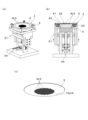
ワークの保持装置1は、図1および図2に示すように、加工対象物となるワークWの太さよりも小さな貫通孔2を複数有する弾性シート3と、前記弾性シート3を広げた状態で装着保持するためのリング状のシート保持環4と、該シート保持環4に装着した前記弾性シート3に対して面方向に張力を加える張力付加機構5と、から概略構成されている。
BEST MODE FOR CARRYING OUT THE INVENTION An embodiment of the present invention will be described below with reference to the drawings.
As shown in FIGS. 1 and 2, the
弾性シート3は、シリコンゴムなどの弾性を有する円形のシート材からなり、張力が加えられていない自然状態において、セラミックコンデンサーなどワークWが四角柱の場合にはそれより小さな貫通孔2を中央の領域に多数開設されている。そして、その厚さはワークWの長さに比較して、僅かに短尺な寸法に設定されている。図面に示す実施形態では、ワークWの大きさが縦×横×長さが0.5mm×0.5mm×1.0mmであり、貫通孔2は少し小さく0.4mm×0.4mmの矩形に設定されている。なお、前記した貫通孔2を開設するには、レーザー加工、打ち抜き加工、型成型などの加工法を用いることができる。そして、孔の配列は適宜選択することができ、図面に示す弾性シート3では格子状に開設してある。
The
前記弾性シート3を広げた状態で装着保持するためのリング状のシート保持環4は、円形の開口を有し、該開口の外側に、弾性シートを保持する保持部を備えたリング本体と、該リング本体に保持した弾性シートに初期張力を加えるプリロード用リングとから構成されている。図3に示すリング本体の実施形態は、前記した弾性シート3の直径よりも小さな開口としての貫通開口穴11aを有する第1のリングとして機能する下リング11と、該下リング11と同様の貫通開口穴12a(即ち、開口)を有して下リング11の上面に被せて間に弾性シート3を挟み付ける第2のリングとしての上リング12と、から構成されており、上リング12と下リング11とで挟み付けた弾性シート3を張るプリロード用リング13を下方から取り付けて一体化できるように構成されている。そして、前記した上リング12と下リング11とが重合する面には、相互に噛み合う段差が挟持部15として形成されており、下リング11の下面にはプリロード用リング13が嵌合する窪部16が内周に沿って形成されている。また、前記プリロード用リング13は、前記窪部16に嵌合するリング状のフランジ部18が取付部として形成されており、該フランジ部18の内周から起立して下リング11の貫通開口穴11aの内周近傍に嵌合可能なリング状の起立壁19が形成されている。
A ring-shaped
シート保持環4に弾性シート3を装着するには、当該弾性シート3を自然に広げた状態で下リング11の上に載せてから上リング12を被せて弾性シート3の外周部分を両リング11,12の間に挟み、この状態で上方からネジ21を締め付けて両リング11,12の挟持部15により弾性シート3の外周部分を挟持する。この状態では、図3(c),(d)に示すように、挟持部15の内周を結ぶ平面上に弾性シート3がさほど張力を受けることなく張架される。
To attach the
その後、図3(e),(f)および図4に示すように、プリロード用リング13を下方から弾性シート3に向けた状態で起立壁19を下リング11の貫通開口穴11a内に挿入させて起立壁19の先端を弾性シート3の下面に当接し、さらに上下リング11側に上昇させる。プリロード用リング13のフランジ部18を下リング11の窪部16内に嵌合すると、起立壁19のフランジ部18の上面からの起立高さが挟持部15から弾性シート3の下面までの寸法よりも高く(大きく)設定してあるので、起立壁19の上周縁端が弾性シート3を押し上げ(図4参照)、これにより弾性シート3にプリロード(初期張力)を付与することができ、この状態を維持させるためにプリロード用リング13の下方からネジ22を締め込んで固定する。この様にして弾性シート3を装着すると、弾性シート3には初期張力が付与されているだけなので、各貫通孔2の大きさは殆ど拡大されることがない。前記実施形態では一辺が0.44mmとなる。
After that, as shown in FIGS. 3(e), (f) and 4, the standing
次に、シート保持環4に装着した弾性シート3に張力を付加する張力付加機構5について説明する。
張力付加機構5は、図1および図2に示す実施形態では、前記シート保持環4を取り付けた状態で上下動するシート側テーブル31と、該シート側テーブル31の上下動に拘わらず不動状態を維持して弾性シート3に当接して張力を付与する、換言するとシート側テーブル31に取り付けたシート保持環4の軸方向に相対的移動する突入部材32とから概略構成されている。
Next, the
In the embodiment shown in FIGS. 1 and 2, the
突入部材32は、基台34上に立設した左右のアップライト35の上端を接続する上梁36上に設けられており、シート保持環4の貫通する開口よりも少し小さな円形リング状の固定支持台37を有し、この固定支持台37上の外側ショルダー部38(シート保持環4の開口内に突入すると弾性シート3に当接する位置に相当する部分)に張力付加部材として高さ基準リング39を配置するとともに、高さ基準リング39のすぐ外側に、複数の回転体40を円形を呈する位置に配置し、前記高さ基準リング39の内側に、弾性シート3の貫通孔2を開設した領域よりも少し広い大きさの丸い着座用受台41を設けてある。
The plunging
複数の回転体40は、シート保持環4の開口の内径よりも小径であって、高さ基準リング39の外側の弾性シート3が当たるショルダー部に同じ高さで複数配設され、各回転体40の軸を固定支持台37の円周の接線方向に対して平行な姿勢とし、且つ個別に回転できるように構成されている。なお、前記固定支持台37、外側ショルダー部38、高さ基準リング39、回転体40の列、着座用受台41は同心円上に配置され、且つシート保持環4と同心円上に位置している。
The plurality of
高さ基準リング39は、シート保持環4の上下位置に関わらずかかわらず弾性シート3の下面(即ち、突入部材32側の面)の位置を規制する、換言すると着座用受台41の平らな上面から弾性シート3の下面までの高さ(間隙)を規制する部材である。具体的には、図6(c)に示すように、前記下回転体40の列の内側において固定支持台37から起立する壁状の円形リングであり、円形を呈する上端(先端)が弾性シート3の突入部材32側の面に当接して当該弾性シート3の位置を規制し、これにより弾性シート3の面と着座用受台41の上面(着座面)との間隔(後述するワークの突出高さ)を規制する。
The
回転体40は、弾性シート3に加えられた張力の方向を円滑かつ効率良く変換することができ、前記したように同心円上に配置すると、張力を同心円の中心から放射方向に均等に作用させることができ、弾性シート3の伸びの均一化、歪防止を図ることができる。したがって、各貫通孔2を、相似形を維持したまま拡張することができる。なお、回転体40は、具体的にはボールベアリング、ローラーベアリング、ローラーなどの少ない抵抗で容易に回転可能であって、張力の方向を変換できる部材であればよい。
The rotating
前記した着座用受台41は、上面と弾性シート3の下面との間隔がワークWの突出長さになるので、ワークWに適合させた位置、前記実施形態では0.25mmの空隙ができる位置に配設されている。また、前記した着座用受台41には、例えば、円周方向に90度位相を変えた位置に上下の貫通孔を開設し、該貫通孔の下方からシート支持ピンを先端が着座用受台41の面から僅かに突出させて、弾性シート3の撓みがなくなるように下方から支持するように構成してもよい(図示せず)。なお、着座用受台41は昇降可能とするなどして、ワークWの大きさに合わせて弾性シ-ト3との間隔を高さ基準リング39と共に調整できるように構成してもよい。また、着座用受台41の着座面の裏側に電磁石などの磁力発生手段を設け、磁性体を含むワークの場合には、ワークに磁力を作用させて弾性シート3の貫通孔2に誘導可能としてもよい。
Since the distance between the upper surface and the lower surface of the
前記した左右のアップライト35の間にはシート側テーブル31を上下移動する駆動機構44が配設されている。具体的は、左右のアップライト35の下部を接続する下梁部46に軸受47を設け、該軸受47に昇降駆動軸48を貫通した状態で設け、該軸受47の下方に突出した昇降駆動軸48に取り付けたプーリー49と駆動モーターのプーリー(図示せず)との間に段付きベルト50を掛け渡し、軸受47の上方に突出した昇降駆動軸48の雄ネジ部分を後述するシート側テーブル31の一部に螺合し、駆動モーターにより昇降駆動軸48を回転することによりシート側テーブル31が上下方向に移動するように構成されている。
A
シート側テーブル31は、前記した突入部材32の上部よりも大きな貫通開口部53aを有してシート保持環4を載せる載置テーブル53と、載置テーブル53の両側から下方に延設した脚片54と、脚片54の上下の途中を左右に接続する横梁55とを備えて概略構成されており、横梁55に設けた雌ネジ部56に前記した昇降駆動軸48を螺合し、前記脚片54とアップライト35との間にガイド部57を配設してある。このため、前記したように、駆動モーターが昇降駆動軸48を一方に回転すると前記雌ネジ部56が上方に移動して脚片54がガイド部57に案内されて上昇し、他方に回転すると前記雌ネジ部56が下方に移動して脚片54がガイド部57に案内されて下降し、これにより載置テーブル53をシート保持環4が載った状態で上下動することができる。そして、前記シート側テーブル31の載置テーブル53には、具体的には矩形を呈する載置テーブル53の四隅にはクランプ具58をそれぞれ設け、これらのクランプ具58により所定位置に載置したシート保持環4をクランプするように構成してある。
The sheet side table 31 includes a mounting table 53 having a through
次に、ワークWとして前記セラミックコンデンサーのチップの両端に外部電極を形成する際に、複数のチップを保持する場合の手順(ワークWの保持方法)について説明する。
先ず、弾性シート3を準備する。この弾性シート3には加工対象となるワークWの太さよりも小さい貫通孔2が多数開設されている。具体的には、一辺0.5mmの角柱で長さが1.0mmのワークWであれば、張力を加えない自然状態で貫通孔2の大きさが0.4mmの矩形の角孔を格子状に開設し、厚さが0.55mmのシリコンゴムシートである。
この弾性シート3を広げて張った第1状態から、第1状態における弾性シート3に対する張力よりも強い張力を弾性シート3に加えて第1状態における貫通孔2よりも孔の大きさが拡大された第2状態に変換する孔拡張工程について具体的に説明する。
Next, a procedure for holding a plurality of chips (workpiece W holding method) when forming external electrodes on both ends of the chip of the ceramic capacitor as the work W will be described.
First, the
From the first state in which the
図3に示すように、上リング12と下リング11との間に弾性シート3を自然状態で配置して弾性シート3の外周部分を挟んで、この状態で上から4本のネジ21で上リング12と下リング11を締結する。その後、下方からプリロード用リング13のフランジ部18を下リング11の窪部16内に嵌合すると共にフランジ部18から起立した起立壁19を弾性シート3の下面に当接して弾性シート3のほぼ大部分を僅かに押し上げて弱い張力を加え、下方から4本のネジ22を締め込んでこの第1状態を維持する。この第1状態においては極く僅かな張力(プリロード)なので、貫通孔2の大きさは一辺約0.44mm、厚さ0.5mm程度である。
As shown in FIG. 3, the
次に、このシート保持環4をワーク保持装置1にセットして張力付加機構5により弾性シート3に張力を加えて貫通孔2を拡張する。具体的には、図5および図6に示すように、シート側テーブル31を上昇した状態でシート保持環4をプリロード用リング13の開口部内に回転体40の列が入り込むようにしてシート保持環4を上から所定位置に合わせて降ろしクランプ具58によりクランプする。なお、この状態においては、図6(c)に示すように、高さ基準リング39の上端が弾性シート3の下面に当接しているが、回転体40は弾性シート3の下面から離間している。
Next, the
そして、前記した初期状態から駆動モーターの駆動によりシート側テーブル31を徐々に下降する。すると、円形状に配設した回転体40の列が弾性シート3の下面に当たり、さらにシート側テーブル31を下降すると、図7に示すように、回転体40の列が弾性シート3を相対的に押し上げることなり弾性シート3に張力を付加する。なお、この状態に変化しても、弾性シート3の下面と着座用受台41の上面との間隔は高さ基準リング39により初期の規定寸法に保たれている。
Then, the seat side table 31 is gradually lowered from the initial state described above by driving the drive motor. Then, the row of
この様にして弾性シート3に第1状態よりも強い張力を付加すると、各貫通孔2が拡張される。具体的には、弾性シート3の厚さが0.38mm程度になるまで張力を加えると貫通孔2の大きさが一辺0,6mmまで拡張され、ワークWが入る大きさの第2状態となる(孔拡張工程)。
By applying a stronger tension to the
次に、図7および図8に示すように、上方から多数のワークWを供給し、拡張された貫通孔2内にワークWを挿入する(ワーク挿入工程)。このワークWの挿入には、パーツフィーダー(フィーダー機構)によりワークWを貫通孔2の位置に合わせて挿入してもよい。パーツフィーダーは、図面には示していないが、例えば、弾性シートを水平方向に向けて挿入操作を行う場合には、パーツフィーダーのボール内周面に斜め上向きに螺旋状に形成した通路に振動を与えてワークを順次整列させ、通路の傾斜上端から直線状に形成した通路内を進行させ、通路先端の下向きに設けた出口を貫通孔2に臨ませ、この状態で出口からワークを1個ずつ送出して貫通孔2内にワークを差し込み、この差し込み操作を移動しながら順次行って全ての貫通孔2内にワークを差し込む構成を採用してもよい。また、通路を複数列設け、一度に複数の出口から送出して複数個所の貫通孔に差し込んむ構成を採ってもよい。要するに、通路は単数でも複数でもよい。また、弾性シート3を縦方向にセットする装置においては、横方向からワークを貫通孔に差し込む構成を採っても良い。この場合においても、パーツフィーダーは,単列でも複数列の通路を備えたものであってよい。
Next, as shown in FIGS. 7 and 8, a large number of works W are supplied from above and inserted into the expanded through holes 2 (work inserting step). The work W may be inserted by aligning the work W with the position of the through-
さらに、ホッパーあるいはストッカー(供給ホッパー機構)から弾性シート3上にワークWを供給して貫通孔2内にワークWを落とし込んでも良い。なお、この場合には、弾性シート3にバイブレータ等の振動付加機構(図示せず)により振動を与えた状態で落とし込むと効率良く入れることができる。
Furthermore, the work W may be supplied onto the
また、ワークWが磁性体を含むものであれば、例えば、内部電極がニッケルなどの磁性体であるワークの場合、着座用受台41の着座面の下に磁石を配置し、磁力を用いて積極的に引き入れるようにしてもよい。この様に、磁力を作用させると、貫通孔内にワークを効率良く引き込むことができ、しかもワークの端を着座用台41の上面に確実に当接させることでワークの突出長さの精度を高めることができる。
さらに、粘着性パレットにワークを所定位置に配置した状態で転写しておき、これらのワークを同時に挿入する構成を採っても良い。この様に構成すると効率良くワークを貫通孔内に入れることができる。
In addition, if the work W contains a magnetic material, for example, in the case of a work whose internal electrodes are made of a magnetic material such as nickel, a magnet is arranged under the seating surface of the
Furthermore, a configuration may be employed in which the works are transferred to the adhesive pallet in a state of being arranged at predetermined positions, and these works are inserted at the same time. With this configuration, the work can be efficiently put into the through hole.
前記のようにして貫通孔2内にワークWを挿入すると、弾性シート3の下方に着座用受台41が配設されており、該着座用受台41の上面と弾性シート2の下面との間隔が高さ基準リング39によって0.25mmに保たれているので、拡張された貫通孔2内に挿入されたワークWの下端が着座用受台41に支持され、下端を弾性シート3の下面から所定長さだけ突出し、上端が弾性シート3の上面から突出した状態で停止する。この実施形態では、ワークWの上端と下端がいずれも0.25mm突出する。
When the workpiece W is inserted into the through
そして、拡張された貫通孔2内にワークWが挿入されたならば、図9に示すように、シート側テーブル31を上昇して初期状態に復帰させる。すると、弾性シート3への張力の付加が解除され、弾性シート3の弾性力により貫通孔2が収縮し、この弾性力を伴う収縮により貫通孔2の内面がワークWを絞り込むように締め付けて殆ど密着した状態でワークWを保持する。この状態になったならば、クランプ具58を緩めてシート保持環4を取り外して、貫通孔2内にワークWを保持した状態で次の工程に移動することができる。
After the work W is inserted into the enlarged through
次の工程においては、例えば、チャンバー内にシート保持環4を入れて蒸着処理やスパッタリングなどの加工を施す。この様にしてワークWの端部に金属皮膜を形成すると、弾性シート3の各貫通孔2の内面がワークWの中間部分に隙間なく密着してワークWの端部だけが突出しているので、この突出した端部だけに外部電極を形成することができ、しかも段差のない外部電極を端面を含めた5面に形成することができる。なお、前記した加工において、弾性シートの温度が上昇して弾性シート自体が熱膨張したとしても、プリロードが付加されているので、加工の途中や加工終了した後においても弾性シートが熱膨張しても張力が僅かに減少するだけであり、貫通孔の内面とワークとの間に隙間が生じることを防止することができる。したがって、加工中におけるマスキング機能の低下を未然に防止して良質な加工を行うことができる。また、貫通孔内にワークを保持した後の行程において、弾性シート3に部分的な応力変化を受けるなどしても、プリロードにより弾性シート3の撓みや歪みを分散・吸収することができる。したがって、貫通孔2内からワークが外れたり、ずれたりするなどの不都合を未然に防止することができる。
In the next step, for example, the
そして、外部電極の形成が終了したならば、チャンバーからシート保持環4を取り出し、図11に示すように、ワーク回収装置61にセットしてワークWを取り外す。このワーク回収装置61は、前記した保持装置1とほぼ同様の構成であるが、着座用受台41に代わって回収空部62を備えている。
Then, when the formation of the external electrodes is completed, the
ワーク回収装置61によりワークWを回収する(ワーク排出方法)には、シート保持環4を載置テーブル53上に載せてクランプ具58で固定し、載置テーブル53を下降して貫通孔2を拡張する。すると、貫通孔2内のワークWが落下して回収空部62に回収することができる。この場合、弾性シート3に振動を与えたり、上方から押圧具63によりワークWを下方に押圧したり(図11(b)参照)、あるいは回収空部62内を減圧したりしてワークWが弾性シ-トから離脱し易くすると、効率良く回収することができる。
また、磁性体を含むワークの場合、ワークを保持した弾性シートの一方から他方に向けて磁力を作用させ、該磁力によりワークを排出してもよい。
なお、ワークを排出した弾性シートは、清浄した後、再度使用することができる。
また、ワーク回収装置61は、前記した保持装置1の着座用受台41を取り外して、その部分に回収空部62を有する部材を取り付けて兼用の装置としてもよい。
要するに、ワークに対して弾性シートの一方から他方に向けて押圧力や吸引力を作用させて離脱の容易化を図ると効率良くワークを取り出す(排出する)ことができる。
In order to collect the work W by the work collection device 61 (work discharge method), the
Moreover, in the case of a work containing a magnetic material, a magnetic force may be applied from one side of the elastic sheet holding the work toward the other side, and the work may be ejected by the magnetic force.
The elastic sheet from which the work has been discharged can be reused after being cleaned.
Further, the
In short, the work can be efficiently taken out (discharged) by applying a pressing force or a suction force to the work from one side of the elastic sheet to the other to facilitate detachment.
さらに、加工対象となるワークWは、前記した四角柱に限定されるものではなく、円柱でもよいし、多角形でもよく、貫通孔2に入る形状であればよい。また、シートを縦方向に向けてワークWを入れてもよい。
Furthermore, the workpiece W to be processed is not limited to the above-described square pole, and may be a cylinder or a polygon as long as it has a shape that can be inserted into the through
そして、前記した実施の形態は全ての点で例示であって制限的なものではないと考えられるべきである。本発明は、上記した説明に限らず特許請求の範囲によって示され、特許請求の範囲と均等の意味及び範囲内での全ての変更が含まれるものである。例えば、張力付加機構は、シート保持環を取り付けるシート側テーブルと、該シート側テーブルに取り付けたシート保持環の軸方向に相対的に移動する突入側テーブルとを備えて弾性シートの貫通孔を拡張する機能を備えていれば、シート側テーブルと突入側テーブルとの移動方向は少なくとも何れか一方を上下方向に移動することができればよく、また、移動方向は横方向であってもよい。また、シート保持環は、上下に分割する構成に限定されるものではなく、弾性シートを広げた状態で装着することができればよい。 Moreover, the above-described embodiments should be considered as examples in all respects and not restrictive. The present invention is defined not only by the above description but also by the scope of the claims, and includes all modifications within the scope and meaning equivalent to the scope of the claims. For example, the tension applying mechanism includes a seat-side table on which a seat-retaining ring is attached, and an entry-side table that moves relatively in the axial direction of the seat-retaining ring attached to the seat-side table to expand the through-hole of the elastic sheet. As long as the function is provided, at least one of the seat side table and the entry side table can be moved vertically, and the moving direction may be the horizontal direction. Further, the seat retaining ring is not limited to a structure in which it is divided into upper and lower parts, and it is sufficient that it can be mounted in a state in which the elastic sheet is spread out.
1 保持装置
2 貫通孔
3 弾性シート
4 シート保持環
5 張力付加機構
11 下リング
11a 貫通開口穴
12 上リング
12a 貫通開口穴
13 プリロード用リング
15 挟持部
16 窪部
18 フランジ部
19 起立壁
21 ネジ
22 ネジ
31 シート側テーブル
32 突入部材
34 基台34
35 アップライト
36 上梁
37 固定支持台
38 外側ショルダー部
39 高さ基準リング
40 回転体
41 着座用受台
44 駆動機構
46 下梁部
47 軸受
48 昇降駆動軸
49 プーリー
50 段付きベルト
53 載置テーブル
53a 貫通開口部
54 脚片
55 横梁
56 雌ネジ部
57 ガイド部
58 クランプ具
61 ワーク回収装置
62 回収空部
63 押圧具
35
Claims (16)
該シート保持環は、円形の開口を有し、該開口の外側に、弾性シートを保持する保持部を備えたリング本体と、該リング本体に保持した弾性シートに初期張力を加えるプリロード用リングとから構成され、
プリロード用リングは、前記リング本体に取り付ける取付部を有し、該取付部から起立してリング本体の開口の内周に沿って入り込むリング状の起立壁を有し、
該起立壁は、前記リング本体に取り付けた状態で、前記保持部により保持した弾性シートに当接して当該弾性シートに対して初期張力を付与し得る起立高さに設定されていることを特徴とするシート保持環。 A ring-shaped sheet retaining ring for mounting and retaining the elastic sheet for retaining a work according to claim 1 or 2 in a spread state,
The sheet retaining ring has a circular opening, a ring body provided with a retaining portion for retaining an elastic sheet outside the opening, and a preloading ring that applies initial tension to the elastic sheet retained in the ring body. consists of
The preload ring has an attachment portion attached to the ring body, and has a ring-shaped standing wall that rises from the attachment portion and enters along the inner circumference of the opening of the ring body,
The standing wall is set to a standing height that can contact the elastic sheet held by the holding part and apply initial tension to the elastic sheet in a state of being attached to the ring body. seat retaining ring.
前記ワーク保持用の弾性シートを広げた状態で装着保持するためのリング状のシート保持環と、
該シート保持環に装着した前記弾性シートに対して面方向に張力を加える張力付加機構と、
を備え、
前記張力付加機構により弾性シートに張力を加えて前記貫通孔を拡張した状態で当該貫通孔内にワークを入れ、この状態で張力付加機構の張力付加を緩めることにより貫通孔を収縮して当該貫通孔内にワークを保持することを特徴とするワークの保持装置。 an elastic sheet for holding a work according to claim 1 or 2;
a ring-shaped sheet holding ring for mounting and holding the elastic sheet for holding the workpiece in a spread state;
a tension applying mechanism that applies tension in a plane direction to the elastic sheet attached to the sheet retaining ring;
with
A workpiece is inserted into the through-hole in a state in which the through-hole is expanded by applying tension to the elastic sheet by the tension-applying mechanism. A workpiece holding device for holding a workpiece in a hole.
前記シート側テーブルは、所定位置に載置したシート保持環をクランプするクランプ具と、クランプしたシート保持環の開口に対応する部分に突入開口部を有し、
前記突入側テーブルは、先端部分がシート保持環の開口よりも小径であって、シート保持環の開口に突入する状態で弾性シートに当たるショルダー部分に複数の回転体を有し、各回転体の回転中心軸が前記ショルダー部分の円周の接線方向に対して平行に配置されていることを特徴とする請求項5に記載のワークの保持装置。 The tension applying mechanism comprises a seat-side table to which the seat-retaining ring is attached, and an entry-side table that moves relatively in the axial direction of the seat-retaining ring attached to the seat-side table,
The seat-side table has a clamping tool for clamping the seat-holding ring placed at a predetermined position, and a plunge opening in a portion corresponding to the opening of the clamped seat-holding ring,
The entry-side table has a front end portion smaller in diameter than the opening of the seat retaining ring, and has a plurality of rotating bodies in a shoulder portion that contacts the elastic sheet in a state of entering the opening of the seat retaining ring. 6. A workpiece holding device according to claim 5, wherein the central axis is arranged parallel to the tangential direction of the circumference of the shoulder portion.
拡大した前記貫通孔内にワークを挿入するワーク挿入工程と、
貫通孔内にワークが挿入された状態から弾性シートの張力を弱めて弾性シートの弾性により前記貫通孔を収縮して、当該ワークの端を貫通孔から露出した状態でワークを保持することを特徴とするワークの保持方法。 From a first state in which an elastic sheet having a through hole smaller than the thickness of a workpiece to be processed is expanded and stretched, a tension stronger than the tension applied to the elastic sheet in the first state is applied to the elastic sheet to form the through hole in the first state. a pore expanding step of converting to a second state in which the pore size is enlarged more than
a workpiece inserting step of inserting a workpiece into the enlarged through hole;
The tension of the elastic sheet is weakened from the state in which the work is inserted into the through hole, and the through hole is contracted by the elasticity of the elastic sheet, and the work is held in a state where the end of the work is exposed from the through hole. How to hold the workpiece.
Priority Applications (2)
| Application Number | Priority Date | Filing Date | Title |
|---|---|---|---|
| JP2022021051A JP2023118219A (en) | 2022-02-15 | 2022-02-15 | Elastic sheet for holding workpiece, sheet holding ring, workpiece holding device, workpiece holding method, and workpiece delivery method |
| PCT/JP2023/001537 WO2023157555A1 (en) | 2022-02-15 | 2023-01-19 | Elastic sheet for holding workpiece, sheet retaining ring, workpiece holding device, workpiece holding method, and workpiece delivery method |
Applications Claiming Priority (1)
| Application Number | Priority Date | Filing Date | Title |
|---|---|---|---|
| JP2022021051A JP2023118219A (en) | 2022-02-15 | 2022-02-15 | Elastic sheet for holding workpiece, sheet holding ring, workpiece holding device, workpiece holding method, and workpiece delivery method |
Publications (1)
| Publication Number | Publication Date |
|---|---|
| JP2023118219A true JP2023118219A (en) | 2023-08-25 |
Family
ID=87578363
Family Applications (1)
| Application Number | Title | Priority Date | Filing Date |
|---|---|---|---|
| JP2022021051A Pending JP2023118219A (en) | 2022-02-15 | 2022-02-15 | Elastic sheet for holding workpiece, sheet holding ring, workpiece holding device, workpiece holding method, and workpiece delivery method |
Country Status (2)
| Country | Link |
|---|---|
| JP (1) | JP2023118219A (en) |
| WO (1) | WO2023157555A1 (en) |
Family Cites Families (11)
| Publication number | Priority date | Publication date | Assignee | Title |
|---|---|---|---|---|
| JPS61296706A (en) * | 1985-06-26 | 1986-12-27 | 関西日本電気株式会社 | Manufacture of ceramic electronic component |
| JPS63138985A (en) * | 1986-12-01 | 1988-06-10 | 松下電器産業株式会社 | Electronic part hodler |
| JPH0590791A (en) * | 1991-09-26 | 1993-04-09 | Japan Tobacco Inc | Work mounting apparatus |
| JPH07122583A (en) * | 1993-10-26 | 1995-05-12 | Fujitsu Ltd | Manufacture of semiconductor device and semiconductor manufacturing apparatus |
| JPH0922845A (en) * | 1995-07-07 | 1997-01-21 | Taiyo Yuden Co Ltd | Method of forming outer electrode of electronic component |
| JPH09183029A (en) * | 1995-12-28 | 1997-07-15 | Taiyo Yuden Co Ltd | Method and device for extracting work |
| JP4013619B2 (en) * | 2002-04-05 | 2007-11-28 | 株式会社村田製作所 | Electronic component handling apparatus and electronic component handling method |
| JP2006321591A (en) * | 2005-05-18 | 2006-11-30 | Taiyo Yuden Co Ltd | Method and device for forming external electrode of chip-shaped electronic component element |
| JP2007123658A (en) * | 2005-10-31 | 2007-05-17 | Disco Abrasive Syst Ltd | Expansion apparatus of adhesive tape |
| JP3928654B1 (en) * | 2005-12-01 | 2007-06-13 | 株式会社村田製作所 | Electronic component measuring apparatus and control method thereof |
| JP2009176767A (en) * | 2008-01-21 | 2009-08-06 | Tdk Corp | Method for manufacturing multilayer ceramic capacitor |
-
2022
- 2022-02-15 JP JP2022021051A patent/JP2023118219A/en active Pending
-
2023
- 2023-01-19 WO PCT/JP2023/001537 patent/WO2023157555A1/en unknown
Also Published As
| Publication number | Publication date |
|---|---|
| WO2023157555A1 (en) | 2023-08-24 |
Similar Documents
| Publication | Publication Date | Title |
|---|---|---|
| US7470120B2 (en) | Configurable die detachment apparatus | |
| US8470130B2 (en) | Universal die detachment apparatus | |
| US3851758A (en) | Semiconductor chip fixture | |
| JP2010161155A (en) | Chip transfer method and chip transfer apparatus | |
| US5288663A (en) | Method for extending wafer-supporting sheet | |
| WO2023157555A1 (en) | Elastic sheet for holding workpiece, sheet retaining ring, workpiece holding device, workpiece holding method, and workpiece delivery method | |
| US7762446B2 (en) | Method and device for transferring a solder deposit configuration | |
| JP4863350B2 (en) | Adhesive sheet and holding jig | |
| US7028396B2 (en) | Semiconductor chip pick and place process and equipment | |
| JPH11308820A (en) | Assembly method and assembly device for motor stator | |
| JPH06275704A (en) | Manufacture of semiconductor chip ejector needle and manufacturing jig thereof | |
| JP5652868B2 (en) | Wafer pallet, component mounter, and dicing sheet mounting method | |
| JP2018179098A (en) | Assembly method and assembly device for thrust roller bearing | |
| JP2005026499A (en) | Center-positioning carrier jig for substrate, method for positioning center and holding method after center positioning | |
| CN114623133A (en) | Magnetic steel assembly bonding tool and bonding method | |
| JP2010182876A (en) | Holding tool and handling equipment of small components | |
| JP4466274B2 (en) | Powder press molding equipment | |
| CN217572633U (en) | Fixing tool for shell part | |
| JP6895300B2 (en) | Thrust roller bearing assembly method and assembly equipment | |
| CN108780788B (en) | Laser marking device and laser marking method | |
| JP2023083668A (en) | Bolt fastening method and workpiece support jig | |
| TWI831174B (en) | Wafer cleaning apparatus and controlling method thereof | |
| CN213905338U (en) | Crystal expansion device and crystal expansion equipment | |
| CN219960974U (en) | Double-layer substrate mounting jig | |
| JP2011027231A (en) | Cvt belt assembling device and cvt belt assembling method |
Legal Events
| Date | Code | Title | Description |
|---|---|---|---|
| A521 | Request for written amendment filed |
Free format text: JAPANESE INTERMEDIATE CODE: A523 Effective date: 20220301 |
|
| RD03 | Notification of appointment of power of attorney |
Free format text: JAPANESE INTERMEDIATE CODE: A7423 Effective date: 20231102 |
|
| A521 | Request for written amendment filed |
Free format text: JAPANESE INTERMEDIATE CODE: A821 Effective date: 20231102 |