JP2022017488A - Roller assembly for grinding device, grinding device, and method - Google Patents
Roller assembly for grinding device, grinding device, and method Download PDFInfo
- Publication number
- JP2022017488A JP2022017488A JP2021180441A JP2021180441A JP2022017488A JP 2022017488 A JP2022017488 A JP 2022017488A JP 2021180441 A JP2021180441 A JP 2021180441A JP 2021180441 A JP2021180441 A JP 2021180441A JP 2022017488 A JP2022017488 A JP 2022017488A
- Authority
- JP
- Japan
- Prior art keywords
- roller
- roller assembly
- bearing
- stopper
- rotation axis
- Prior art date
- Legal status (The legal status is an assumption and is not a legal conclusion. Google has not performed a legal analysis and makes no representation as to the accuracy of the status listed.)
- Granted
Links
- 238000000034 method Methods 0.000 title claims abstract description 16
- 238000000227 grinding Methods 0.000 title abstract description 17
- 238000003801 milling Methods 0.000 claims description 21
- 230000007246 mechanism Effects 0.000 claims description 18
- 230000008878 coupling Effects 0.000 claims description 17
- 238000010168 coupling process Methods 0.000 claims description 17
- 238000005859 coupling reaction Methods 0.000 claims description 17
- 238000005096 rolling process Methods 0.000 claims description 16
- 239000000314 lubricant Substances 0.000 claims description 15
- 230000036316 preload Effects 0.000 claims description 15
- 230000013011 mating Effects 0.000 claims description 9
- 238000009434 installation Methods 0.000 claims description 5
- 230000000284 resting effect Effects 0.000 claims 1
- 230000005540 biological transmission Effects 0.000 description 18
- 230000000712 assembly Effects 0.000 description 8
- 238000000429 assembly Methods 0.000 description 8
- 239000000463 material Substances 0.000 description 6
- 238000006073 displacement reaction Methods 0.000 description 4
- 230000000694 effects Effects 0.000 description 4
- 230000002411 adverse Effects 0.000 description 3
- 238000005461 lubrication Methods 0.000 description 3
- 238000007789 sealing Methods 0.000 description 3
- GXCLVBGFBYZDAG-UHFFFAOYSA-N N-[2-(1H-indol-3-yl)ethyl]-N-methylprop-2-en-1-amine Chemical compound CN(CCC1=CNC2=C1C=CC=C2)CC=C GXCLVBGFBYZDAG-UHFFFAOYSA-N 0.000 description 2
- 230000003213 activating effect Effects 0.000 description 2
- 230000008859 change Effects 0.000 description 2
- 235000013312 flour Nutrition 0.000 description 2
- 238000007689 inspection Methods 0.000 description 2
- 229920002472 Starch Polymers 0.000 description 1
- 241000209140 Triticum Species 0.000 description 1
- 235000021307 Triticum Nutrition 0.000 description 1
- 238000010521 absorption reaction Methods 0.000 description 1
- 230000006978 adaptation Effects 0.000 description 1
- 230000007423 decrease Effects 0.000 description 1
- 230000001419 dependent effect Effects 0.000 description 1
- 238000009826 distribution Methods 0.000 description 1
- 239000004519 grease Substances 0.000 description 1
- 230000004048 modification Effects 0.000 description 1
- 238000012986 modification Methods 0.000 description 1
- 239000002245 particle Substances 0.000 description 1
- 239000013618 particulate matter Substances 0.000 description 1
- 238000003825 pressing Methods 0.000 description 1
- 230000009467 reduction Effects 0.000 description 1
- 235000019698 starch Nutrition 0.000 description 1
- 239000008107 starch Substances 0.000 description 1
- 239000000126 substance Substances 0.000 description 1
- XLYOFNOQVPJJNP-UHFFFAOYSA-N water Substances O XLYOFNOQVPJJNP-UHFFFAOYSA-N 0.000 description 1
Images


Classifications
-
- B—PERFORMING OPERATIONS; TRANSPORTING
- B02—CRUSHING, PULVERISING, OR DISINTEGRATING; PREPARATORY TREATMENT OF GRAIN FOR MILLING
- B02C—CRUSHING, PULVERISING, OR DISINTEGRATING IN GENERAL; MILLING GRAIN
- B02C4/00—Crushing or disintegrating by roller mills
- B02C4/28—Details
- B02C4/32—Adjusting, applying pressure to, or controlling the distance between, milling members
-
- B—PERFORMING OPERATIONS; TRANSPORTING
- B02—CRUSHING, PULVERISING, OR DISINTEGRATING; PREPARATORY TREATMENT OF GRAIN FOR MILLING
- B02C—CRUSHING, PULVERISING, OR DISINTEGRATING IN GENERAL; MILLING GRAIN
- B02C4/00—Crushing or disintegrating by roller mills
- B02C4/02—Crushing or disintegrating by roller mills with two or more rollers
- B02C4/06—Crushing or disintegrating by roller mills with two or more rollers specially adapted for milling grain
-
- B—PERFORMING OPERATIONS; TRANSPORTING
- B02—CRUSHING, PULVERISING, OR DISINTEGRATING; PREPARATORY TREATMENT OF GRAIN FOR MILLING
- B02C—CRUSHING, PULVERISING, OR DISINTEGRATING IN GENERAL; MILLING GRAIN
- B02C4/00—Crushing or disintegrating by roller mills
- B02C4/28—Details
-
- B—PERFORMING OPERATIONS; TRANSPORTING
- B02—CRUSHING, PULVERISING, OR DISINTEGRATING; PREPARATORY TREATMENT OF GRAIN FOR MILLING
- B02C—CRUSHING, PULVERISING, OR DISINTEGRATING IN GENERAL; MILLING GRAIN
- B02C4/00—Crushing or disintegrating by roller mills
- B02C4/28—Details
- B02C4/32—Adjusting, applying pressure to, or controlling the distance between, milling members
- B02C4/38—Adjusting, applying pressure to, or controlling the distance between, milling members in grain mills
-
- G—PHYSICS
- G05—CONTROLLING; REGULATING
- G05G—CONTROL DEVICES OR SYSTEMS INSOFAR AS CHARACTERISED BY MECHANICAL FEATURES ONLY
- G05G1/00—Controlling members, e.g. knobs or handles; Assemblies or arrangements thereof; Indicating position of controlling members
- G05G1/015—Arrangements for indicating the position of a controlling member
-
- G—PHYSICS
- G05—CONTROLLING; REGULATING
- G05G—CONTROL DEVICES OR SYSTEMS INSOFAR AS CHARACTERISED BY MECHANICAL FEATURES ONLY
- G05G1/00—Controlling members, e.g. knobs or handles; Assemblies or arrangements thereof; Indicating position of controlling members
- G05G1/08—Controlling members for hand actuation by rotary movement, e.g. hand wheels
- G05G1/10—Details, e.g. of discs, knobs, wheels or handles
Abstract
Description
本発明は、粉砕装置のためのローラアセンブリと、粉砕装置と、ローラアセンブリのローラ同士の間に作用する半径方向の力を検出するための方法とに関する。 The present invention relates to a roller assembly for a crusher and a method for detecting a radial force acting between the crusher and the rollers of the roller assembly.
粒子状の粉砕材料を粉砕するための種々の種類の粉砕装置が、多種多様な産業用途のために使用されている。これらの装置には、例えば、製粉ローラ粉砕機、麦芽製粉用ミル、飼料用ミル、およびコーヒーミルが含まれる。そのような粉砕装置は、1つまたは複数のローラアセンブリを含み、このローラアセンブリは、それぞれ少なくとも2つのローラを有する。ローラは、それぞれの軸受本体によって保持可能である。ローラ同士の間には粉砕間隙が形成されており、多くのローラアセンブリでは、例えば、軸受本体同士が互いに位置調整可能であることにより、この粉砕間隙を調整することができる。 Various types of grinding equipment for grinding particulate matter are used for a wide variety of industrial applications. These devices include, for example, a milling roller grinder, a malt milling mill, a feed mill, and a coffee mill. Such a grinder comprises one or more roller assemblies, each of which has at least two rollers. The rollers can be held by each bearing body. A crushing gap is formed between the rollers, and in many roller assemblies, for example, the bearing bodies can be positioned and adjusted with each other, so that the crushing gap can be adjusted.
公知のローラアセンブリは、実質的に同じ原理に基づいて設計されている。すなわち、機械的、空気圧的、または電気機械的な駆動部によって、可動に取り付けられたローラを動作間隙へと変位させることにより、粉砕間隙の幅を縮小すること、すなわち「押し込む」ことができるようになっている。次いで、この動作間隙を、例えば手動または電動の手段によって動作中にさらに適合させることができる。 Known roller assemblies are designed on substantially the same principle. That is, the width of the crushing gap can be reduced, or "pushed", by displacing the movably mounted roller into the working gap by a mechanical, pneumatic, or electromechanical drive. It has become. This operating gap can then be further adapted during operation, for example by manual or motorized means.
独国特許発明第595934号明細書および独国特許発明第597775号明細書は、ミリングローラの接触圧力を調整するための装置を開示している。これらの装置は、硬い異物の通過時にミリングローラを偏向させることができる設定可能なばね手段を含む。 German Patented Invention No. 595934 and German Patented Invention No. 5977775 disclose an apparatus for adjusting the contact pressure of a milling roller. These devices include configurable spring means that can deflect the milling rollers as hard foreign matter passes through.
ローラアセンブリは、ある程度の剛性を有し、この剛性は、ローラ同士の間に作用する半径方向の力と、粉砕間隙の幅とに依存していることを特徴とし得る。 The roller assembly may have some stiffness, which may be characterized by a radial force acting between the rollers and the width of the crushing gap.
この剛性は、ローラアセンブリのローラの剛性と、転がり軸受の剛性と、残りのコンポーネントの剛性とから構成される。したがって、押し込まれた状態では、ローラの位置は、粉砕間隙内に存在する力に依存している。この力は、主として、粉砕間隙の拡大をもたらす半径方向の力である。この力が一定である限り、この力は、動作中に修正可能であるので、悪影響を及ぼすことはない。 This stiffness consists of the stiffness of the rollers in the roller assembly, the stiffness of the rolling bearings, and the stiffness of the remaining components. Therefore, in the pushed state, the position of the roller depends on the force existing in the crushing gap. This force is primarily a radial force that results in the expansion of the crushing gap. As long as this force is constant, it can be modified during operation and will not have an adverse effect.
しかしながら、困難をもってしかローラ同士の間に引き込むことができない粉砕材料の場合には、粉砕間隙内の力が非常に変動しやすくなる。粉砕材料が粉砕間隙を通過すると、ローラ同士が押し離される。短時間の間、粉砕材料が引き込まれない場合には、ローラ同士が互いに接触する。このような状況では、間隙の剛性が、粉砕材料の挙動および特性に大きな影響を及ぼす。 However, in the case of a crushing material that can be drawn between the rollers only with difficulty, the force in the crushing gap is very likely to fluctuate. When the crushing material passes through the crushing gap, the rollers are pushed apart. If the grinding material is not drawn in for a short period of time, the rollers come into contact with each other. In such situations, the stiffness of the gap has a significant effect on the behavior and properties of the ground material.
本発明の第1の目的は、公知のローラアセンブリの欠点を克服することである。できるだけ均一な特性を有する粉砕材料を製造することができるようにするために、粉砕間隙の幅ができるだけ一定に維持されるローラアセンブリを提供することが、特に意図されている。 A first object of the present invention is to overcome the shortcomings of known roller assemblies. It is specifically intended to provide a roller assembly in which the width of the milling gap is maintained as constant as possible so that a milling material with as uniform properties as possible can be produced.
上記の目的およびさらなる目的は、本発明の第1の態様において、少なくとも1つの第1の軸受本体によって保持されている第1のローラと、少なくとも1つの第2の軸受本体によって保持されている第2のローラとを含む、粉砕装置のためのローラアセンブリによって達成される。第1のローラと第2のローラとの間に形成される粉砕間隙を調整することができるように、第1の軸受本体および第2の軸受本体を互いに対して位置調整することができる。例えば、第2の軸受本体は、第1の軸受本体上で枢動可能に支持可能である。第1の軸受本体および第2の軸受本体には、緊締装置によって、第1のローラと第2のローラとが互いに向かって押し付けられるように、互いに予荷重を加えることができる。 The above and further objectives are, in the first aspect of the invention, a first roller held by at least one first bearing body and a first roller held by at least one second bearing body. Achieved by a roller assembly for a grinder, including two rollers. The position of the first bearing body and the second bearing body can be adjusted with respect to each other so that the crushing gap formed between the first roller and the second roller can be adjusted. For example, the second bearing body can be pivotally supported on the first bearing body. A preload can be applied to the first bearing body and the second bearing body by a tightening device so that the first roller and the second roller are pressed against each other.
本発明によれば、第1の軸受本体が、第1のストッパ面を備える少なくとも1つの第1のストッパ本体を有し、第2の軸受本体が、第2のストッパ面を備える少なくとも1つの第2のストッパ本体を有し、ストッパ面が、当該ストッパ面同士の接触がローラ同士の接触を阻止するように、軸受本体上に形成および配置されているか、または配置可能である、ようにすることが企図されている。ここおよび以下において、「接触を阻止する」という用語は、ローラ同士の接触が完全に防止されることを意味するとは必ずしも理解されない。事前に規定された非常に小さい粉砕間隙幅の場合には、ローラ同士の接触も、本発明の範囲内において許容される。 According to the present invention, the first bearing body has at least one first stopper body with a first stopper surface, and the second bearing body has at least one first stopper surface with a second stopper surface. It has 2 stopper bodies so that the stopper surfaces are formed and arranged on the bearing body or can be arranged so that the contact between the stopper surfaces prevents the contact between the rollers. Is intended. Here and below, the term "preventing contact" is not necessarily understood to mean that contact between rollers is completely prevented. In the case of a very small pre-defined crushing gap width, contact between rollers is also allowed within the scope of the present invention.
さらに、第1のストッパ本体は、第1の回転軸線を中心にして回転可能である。第1のストッパ面は、第1のストッパ本体の、第1の回転軸線に対して偏心している円周面によって形成されており、特に、第1のストッパ本体の回転位置が、粉砕間隙の最小幅を決定するようになっている。ここおよび以下において、第1のストッパ本体の円周面は、この円周面が第1の回転軸線に対して回転対称でない場合に、すなわち、第1のストッパ本体が第1の回転軸線を中心にして少なくとも0°より大きく360°より小さい角度だけ回転した結果としてこの円周面自体が変化している場合に、偏心していると称される。 Further, the first stopper body can rotate about the first rotation axis. The first stopper surface is formed by the circumferential surface of the first stopper body that is eccentric with respect to the first rotation axis, and in particular, the rotation position of the first stopper body is the maximum of the crushing gap. It is designed to determine the small width. Here and below, the circumferential surface of the first stopper body is when the circumferential surface is not rotationally symmetric with respect to the first rotation axis, that is, the first stopper body is centered on the first rotation axis. When the circumferential surface itself changes as a result of rotation by at least an angle larger than 0 ° and smaller than 360 °, it is said to be eccentric.
本発明によるローラアセンブリでは、粉砕間隙内に存在する力が変化した場合には、軸受本体同士の間の予荷重のみが変化するが、軸受本体同士の相対位置は変化しない。したがって、粉砕間隙に関する唯一の柔軟性は、ローラおよび軸受に起因する。第1のストッパ本体を回転させることにより、例えば澱粉の損傷、吸水、および特に小麦粉の粒径分布のような粉砕される粉砕材料の特性を、正確に設定することが可能になる(特に、粉砕装置に供給される質量流量の変動に起因して、間隙の占有率、ひいては間隙の力が変化する場合)。 In the roller assembly according to the present invention, when the force existing in the crushing gap changes, only the preload between the bearing bodies changes, but the relative position between the bearing bodies does not change. Therefore, the only flexibility with respect to the crush gap is due to the rollers and bearings. By rotating the first stopper body, it is possible to accurately set the characteristics of the milled material to be ground, such as starch damage, water absorption, and especially the particle size distribution of wheat flour (particularly, milling). If the occupancy of the gap, and thus the force of the gap, changes due to fluctuations in the mass flow rate supplied to the device).
ストッパ本体同士が接触しない状況、したがって、粉砕間隙の幅が大きくなりすぎる状況を防止するために、ストッパ本体同士の間に存在する、緊締装置からの予荷重を、粉砕間隙内に存在する力から生じる、ストッパ本体同士の間の最大予想力よりも大きくすべきである。 In order to prevent the situation where the stopper bodies do not come into contact with each other, and therefore the width of the crushing gap becomes too large, the preload from the tightening device existing between the stopper bodies is applied from the force existing in the crushing gap. It should be greater than the maximum expected force between the stopper bodies that arises.
緊締装置は、ローラアセンブリの構成部分であり得る。しかしながら、緊締装置を、粉砕装置の機械台の構成部分とし、ローラアセンブリが、緊締装置との解離可能な結合のための連結装置を有するようにすることが好ましい。これにより、ローラアセンブリの取り付けおよび取り外しが容易になる。この結合により、機械台の緊締装置は、ローラアセンブリの軸受本体に予荷重を加えることができる。連結装置は、軸受本体のうちの1つに配置可能である。 The tightening device can be a component of the roller assembly. However, it is preferred that the tightening device be a component of the machine base of the crushing device so that the roller assembly has a coupling device for dissociable coupling with the tightening device. This facilitates the installation and removal of the roller assembly. This coupling allows the machine base tightening device to preload the bearing body of the roller assembly. The coupling device can be arranged in one of the bearing bodies.
第1のストッパ本体の円周面は、第1の回転軸線に対して円筒形であり得る。第1の回転軸線に対する円周方向において、円周面は、例えば、少なくとも特定の部分において螺旋の形状を有することができる。螺旋によって理解されるべきことは、第1の回転軸線から円周面までの距離が、角度に応じて大きくなったり、または小さくなったりするということである。螺旋は、好ましくは、距離が角度に線形に依存するアルキメデス螺旋である。 The circumferential surface of the first stopper body may be cylindrical with respect to the first rotation axis. In the circumferential direction with respect to the first axis of rotation, the circumferential surface can have, for example, a spiral shape at least in a particular portion. What should be understood by the spiral is that the distance from the first axis of rotation to the circumferential surface increases or decreases depending on the angle. The helix is preferably an Archimedes helix whose distance is linearly dependent on the angle.
第2のストッパ本体が、第1の回転軸線に対して平行な第2の回転軸線を中心にして回転可能であり、第2のストッパ面が、第2のストッパ本体の、第2の回転軸線に対して回転対称である円周面によって形成されていると、有利である。なぜなら、粉砕間隙の幅を調整するために第1のストッパ本体を回転させると、2つのストッパ本体の円周面は、互いの上で転動することができ、その結果、摩擦が大幅に減少するので、調整が容易になるからである。ストッパ本体同士は、好ましくは高度の予荷重で互いに押し付けられるので、このことは、本発明の範囲内において重要である。 The second stopper body can rotate about the second rotation axis parallel to the first rotation axis, and the second stopper surface is the second rotation axis of the second stopper body. It is advantageous if it is formed by a circumferential surface that is rotationally symmetric with respect to the above. This is because when the first stopper body is rotated to adjust the width of the crushing gap, the circumferential surfaces of the two stopper bodies can roll on each other, resulting in a significant reduction in friction. This is because the adjustment becomes easy. This is important within the scope of the present invention, as the stopper bodies are preferably pressed against each other with a high preload.
さらに、第1のストッパ本体の第1の回転軸線および/または第2のストッパ本体の第2の回転軸線が、特に第1の回転軸線に対して垂直な方向に変位可能に配置されていると、好適である。第1のストッパ本体の回転は、粉砕間隙の微調整をもたらすが、その一方で、粉砕間隙の大まかな調整は、少なくとも1つのストッパ本体を変位させることによって達成可能である。 Further, if the first rotation axis of the first stopper body and / or the second rotation axis of the second stopper body are arranged so as to be displaceable in a direction perpendicular to the first rotation axis in particular. , Suitable. The rotation of the first stopper body results in a fine adjustment of the crushing gap, while the rough adjustment of the crushing gap can be achieved by displacing at least one stopper body.
ローラアセンブリが、ハンドルを有し、ハンドルが、ハンドル回転軸線を中心にして可能であって、かつ当該ハンドルの回転が第1のストッパ本体の回転を引き起こすように、ハンドル伝動機構を介して第1のストッパ本体に結合されていると、微調整がさらに容易になる。公知のように、伝動機構は、ハンドルに対する比較的小さなトルクが、第1のストッパ本体における大きなトルクに変換されるように選択可能である。ハンドル伝動機構は、好ましくは、できるだけ高い効率を有するべきである。ハンドル上のできるだけ正確な位置の指示と、第1のストッパ本体のできるだけ正確な位置決めとを可能にするために、伝動機構に小さいバックラッシュを設けることも有利である。ストッパ本体同士は、好ましくは高度の予荷重で互いに押し付けられるので、このことは全て、本発明の範囲内において重要である。さらに、ハンドル伝動機構が、複数の伝動機構入力部、特に、ハンドルのための第1の伝動機構入力部と、電動での調整を可能にするための第2の伝動機構入力部とを有することが好ましい。 A first via a handle transmission mechanism such that the roller assembly has a handle, the handle is possible about the handle rotation axis, and the rotation of the handle causes the rotation of the first stopper body. When connected to the stopper body of, fine adjustment becomes easier. As is known, the transmission mechanism can be selected so that a relatively small torque to the handle is converted into a large torque in the first stopper body. The handle transmission mechanism should preferably have as high an efficiency as possible. It is also advantageous to provide a small backlash in the transmission mechanism to allow as accurate position indication as possible on the handle and as accurate positioning of the first stopper body as possible. This is all important within the scope of the present invention, as the stopper bodies are preferably pressed against each other with a high preload. Further, the handle transmission mechanism has a plurality of transmission mechanism input units, particularly a first transmission mechanism input unit for the handle and a second transmission mechanism input unit for enabling electric adjustment. Is preferable.
本発明は、上記のようなローラアセンブリを動作させるための方法も含む。本方法は、第1の軸受本体および第2の軸受本体に、緊締装置によって、第1のローラと第2のローラとが互いに向かって押し付けられるように、互いに予荷重を加えるステップを含む。 The present invention also includes a method for operating a roller assembly as described above. The method comprises the step of preloading the first bearing body and the second bearing body with each other so that the first roller and the second roller are pressed against each other by a tightening device.
本方法は、粉砕間隙の最小幅を設定するために、第1のストッパ本体を、第1の回転軸線を中心にして回転させるさらなるステップを含むことができる。 The method can include a further step of rotating the first stopper body about the first rotation axis in order to set the minimum width of the crushing gap.
さらに、ローラアセンブリが、力測定装置を有し、力測定装置が、第1の軸受本体および第2の軸受本体に互いに予荷重を加えている第1の力を検出するための第1のセンサと、第1のストッパ本体と第2のストッパ本体との間に作用する第2の力を検出するための第2のセンサとを含むと、好適である。一方または両方のセンサは、力を直接的に検出するための力センサであり得る。しかしながら、これに代えて、2つのセンサのうちの少なくとも1つを、例えば圧力センサとして力を間接的に検出するように設計してもよく、この圧力センサを用いてシリンダ(特に、以下でさらに説明するベローズシリンダ)内に存在する圧力を検出して、この圧力から関連する力を算出してもよい。センサによって直接的または間接的に検出された2つの力から、ローラ同士の間に作用する力を計算することができる。 Further, the roller assembly has a force measuring device, and the force measuring device detects a first force that preloads the first bearing body and the second bearing body with each other. It is preferable to include a second sensor for detecting a second force acting between the first stopper main body and the second stopper main body. One or both sensors can be force sensors for directly detecting force. However, instead, at least one of the two sensors may be designed to indirectly detect force, eg, as a pressure sensor, using this pressure sensor for cylinders (especially further below. The pressure present in the bellows cylinder described) may be detected and the associated force may be calculated from this pressure. From the two forces directly or indirectly detected by the sensor, the force acting between the rollers can be calculated.
第1のセンサは、例えば、緊締装置に組み込み可能である。第2のセンサは、例えば、第2のストッパ本体上に配置可能である。 The first sensor can be incorporated into, for example, a tightening device. The second sensor can be arranged, for example, on the second stopper body.
本発明は、そのようなローラアセンブリのローラ同士の間に作用する半径方向の力を検出するための方法も含む。本方法は、ローラの間に作用する力を、センサによって検出された力から計算するステップを含む。 The invention also includes methods for detecting radial forces acting between the rollers of such roller assemblies. The method comprises calculating the force acting between the rollers from the force detected by the sensor.
(ギャップセンサまたはエンコーダのような電子要素を用いることなく)できるだけ簡単なやり方で、上で既に述べたようなハンドルの位置を示すために、従来技術では、位置インジケータが使用される。動作間隙が所期のように設定されている場合には、位置インジケータを回転させることによって、ハンドルの位置が参照される。したがって、粉砕間隙の所要の適合により、基本状態を簡単に取得することが可能である。位置インジケータは、ハンドル内に収容されており、従来技術では、ラジアル調整ねじによって挟持されており、これによって回転または滑落に対して保護されている。もう1つの変形例は、後側に向かって軸方向に荷重を加えることである。しかしながら、粉砕動作中に発生する振動が、位置インジケータに対してかなりの悪影響を及ぼす可能性がある。 In the prior art, position indicators are used to indicate the position of the handle as already mentioned above in the simplest way possible (without the use of electronic elements such as gap sensors or encoders). If the operating gap is set as desired, the position of the handle is referenced by rotating the position indicator. Therefore, it is possible to easily obtain the basic state by the required adaptation of the crushing gap. The position indicator is housed within the handle and, in the prior art, is sandwiched by a radial adjusting screw, which protects against rotation or slippage. Another variant is to apply an axial load towards the rear. However, vibrations generated during the grinding operation can have a significant adverse effect on the position indicator.
この点に関して、オイルで充填された位置インジケータは、確かによりロバストである。しかしながら、位置インジケータを挟持することは、さらに危機的である。というのも、荷重が弱すぎると、位置インジケータが脱落してしまい、荷重が強すぎると、破損する可能性があるからである。特殊なねじを使用してこの問題を克服することは、既に試みられている。しかしながら、このような特殊なねじは、紛失する可能性がある。従来のねじに交換すると、漏れが発生する場合がある。その他の欠点は、参照するために工具が必要であることと、ねじが小さくてしばしばアクセスしにくいことである。 In this regard, the oil-filled position indicator is certainly more robust. However, pinching the position indicator is even more critical. This is because if the load is too weak, the position indicator will fall off, and if the load is too strong, it may be damaged. Overcoming this problem with special screws has already been attempted. However, such special screws can be lost. Leakage may occur when replacing with conventional screws. Other drawbacks are the need for tools to reference and the small size of the screws, which are often inaccessible.
本発明のさらなる目的は、これらの欠点を克服することと、特に、粉砕中に発生する振動に耐えることができ、かつ容易に設定することができる位置インジケータを有するローラアセンブリを提供することとにある。 A further object of the present invention is to overcome these shortcomings and, in particular, to provide a roller assembly with a position indicator that can withstand the vibrations that occur during grinding and that can be easily set. be.
この目的を達成するために、本発明の第2の態様では、粉砕装置のためのローラアセンブリであって、当該ローラアセンブリは、第1のローラおよび第2のローラと、ハンドル回転軸線を中心にして回転可能であって、かつ第1のローラと第2のローラとの間に形成された粉砕間隙を調節することができるハンドルとを含む、ローラアセンブリが提案される。このローラアセンブリは、例えば、上記のようなローラアセンブリであり得る。本発明によれば、ローラアセンブリが、ハンドルの位置を示すための位置インジケータを有し、位置インジケータが、位置インジケータハウジングと、インジケータ要素とを含み、インジケータ要素が、位置インジケータハウジングに対してハンドル回転軸線に沿って移動可能であり、インジケータ要素には、位置インジケータばねによって、位置インジケータハウジングに対してハンドル回転軸線の方向に予荷重が加えられているか、または予荷重を加えることができ、インジケータ要素が、保持位置において、位置インジケータハウジングに接触することにより、ハンドル回転軸線を中心にした回転に対して保護されるようになっており、かつ位置インジケータばねによってもたらされた予荷重を克服した場合にのみ、ハンドル回転軸線を中心にして回転することができるようになっている、ようにすることが企図されている。 To achieve this object, a second aspect of the invention is a roller assembly for a crusher, the roller assembly centered on a first roller and a second roller and a handle rotation axis. A roller assembly is proposed that includes a handle that is rotatable and capable of adjusting the grinding gap formed between the first roller and the second roller. This roller assembly can be, for example, a roller assembly as described above. According to the present invention, the roller assembly has a position indicator for indicating the position of the handle, the position indicator includes a position indicator housing and an indicator element, and the indicator element rotates the handle with respect to the position indicator housing. Movable along the axis, the indicator element is preloaded or can be preloaded in the direction of the handle rotation axis with respect to the position indicator housing by the position indicator spring, the indicator element. However, in the holding position, by contacting the position indicator housing, it is protected against rotation about the handle rotation axis and overcomes the preload provided by the position indicator spring. It is intended that only the housing can be rotated about the axis of rotation of the handle.
インジケータ要素を参照中に回転させることができるようにするためには、このインジケータ要素を、予荷重に対抗して手動で押すだけでよく、このようにして回転させることができる。これにより、前述のねじおよび工具の必要性が省略される。さらに、粉砕動作中の振動の邪魔な影響を、効果的に防止することができる。 In order to be able to rotate the indicator element in reference, the indicator element only needs to be manually pushed against the preload and can be rotated in this way. This eliminates the need for screws and tools mentioned above. Further, it is possible to effectively prevent the disturbing influence of vibration during the crushing operation.
1つの可能な実施形態では、インジケータ要素および位置インジケータハウジングは、接触面を有し、この接触面により、保持位置における形状結合(嵌め合いや凹凸に基づく結合)による係合が可能になる。結果として、粉砕動作中の振動の悪影響を、特に効果的に抑制することができる。しかしながら、形状結合による係合に代えてまたはこれに加えて、保持位置における摩擦結合による係合を設けることも可能である。 In one possible embodiment, the indicator element and the position indicator housing have a contact surface that allows engagement by shape coupling (fitting or coupling based on unevenness) at the holding position. As a result, the adverse effect of vibration during the crushing operation can be suppressed particularly effectively. However, it is also possible to provide frictional coupling at the holding position in place of or in addition to the shape coupling engagement.
例えば検査目的のために、粉砕装置の1つまたは複数のローラを交換することが時々必要とされる。この目的のために、ローラアセンブリは、少なくとも1つのころを備える組み込まれた転動装置を有することができ、少なくとも1つのころは、ローラアセンブリを水平な基礎上に配置することができるように、かつローラアセンブリが少なくとも1つのころによって水平な基礎上を移動することができるように、ローラアセンブリに配置されているか、または配置可能である。 It is sometimes necessary to replace one or more rollers in the grinder, for example for inspection purposes. For this purpose, the roller assembly can have a built-in rolling device with at least one roller so that the roller assembly can be placed on a horizontal foundation at least one roller. And the roller assembly is located or can be placed on the roller assembly so that it can be moved on a horizontal foundation by at least one roller.
軸受本体の転がり軸受においてローラを支承するためには潤滑剤を使用する必要があるが、この潤滑剤が軸受から制御されずに漏出することを、防止すべきである。過剰な潤滑または過酷な取り付け条件に対してはロバストであっても、潤滑剤の漏出を完全には防止することができないようなシーリングシステムが存在する。 A lubricant must be used to support the rollers in the rolling bearings of the bearing body, but this lubricant should be prevented from leaking out of the bearing without control. There are sealing systems that cannot completely prevent lubricant leakage, even if they are robust against excessive lubrication or harsh mounting conditions.
潤滑剤の制御された漏出を可能にするために、ローラのローラ軸部を支持する転がり軸受の軸受カバーは、自身の内側に、潤滑剤のための案内溝を有することができ、案内溝は、ローラ軸部の周りに延在していて、かつ出口開口部に接続されており、出口開口部を介して案内溝から潤滑剤を排出することができる。出口開口部の下には、潤滑剤を収集するための収集装置、例えば収集容器を配置することができる。漏出した潤滑剤を意図した通りに収集することにより、費用効果が高くて組み立てが容易であり、過剰な潤滑の危険性がなく、それと同時に、粉砕装置の衛生的な操作を可能にするような、ロバストなシーリング設計が可能になる。 In order to allow controlled leakage of lubricant, the bearing cover of the rolling bearing that supports the roller shaft of the roller can have a guide groove for the lubricant inside itself, the guide groove , Extending around the roller shaft and connected to the outlet opening, the lubricant can be drained from the guide groove through the outlet opening. Below the outlet opening, a collection device for collecting lubricant, such as a collection container, can be placed. By collecting the leaked lubricant as intended, it is cost effective, easy to assemble, there is no risk of over-lubrication, and at the same time it allows for hygienic operation of the crusher. , Robust sealing design is possible.
ローラの全長にわたって均一な粉砕を達成するために、ローラには、しばしばクラウンが付けられている。それにもかかわらず、ローラの全長にわたって均一な粉砕動作を達成することができない場合には、クラウンを適合させることができる。間隙調整に加えて、ローラを斜めにすること、すなわちローラ軸線を傾けることにより、ローラの長さ全体にわたって粉砕に影響を与えるための、かつより均一な粉砕を実現するための制御変数が得られる。この目的のために、第1のローラは、2つの第1の軸受本体によって保持されており、第2のローラは、2つの第2の軸受本体によって保持されており、第1の軸受本体同士は、互いに独立して位置調整可能であり、かつ/または第2の軸受本体同士は、互いに独立して位置調整可能である、ようにすることを企図することができる。 Rollers are often crowned to achieve uniform grinding over the entire length of the roller. Nevertheless, if it is not possible to achieve a uniform grinding operation over the entire length of the roller, the crown can be fitted. In addition to clearance adjustment, tilting the roller, i.e. tilting the roller axis, provides control variables to affect grinding over the entire length of the roller and to achieve more uniform grinding. .. For this purpose, the first roller is held by two first bearing bodies, the second roller is held by two second bearing bodies, and the first bearing bodies are held together. Can be intended to be position adjustable independently of each other and / or position of the second bearing bodies independently of each other.
1つの可能な実施形態では、このことは、第2の軸受本体が、枢動ボルトを介して第1の軸受本体上で枢動可能に支持されており、枢動ボルトが、第1の軸受本体に対して例えば垂直方向に調整可能であることによって達成可能である。このことは、例えば、第1の軸受本体がくさびを有し、このくさびを、第1の軸受本体に対する第1の方向へのくさびの変位が、第1の軸受本体に対する、第1の方向とは異なる第2の方向への枢動ボルトの変位を生ぜしめるように形成および配置することによって実現可能である。しかしながら、これに代えて、第2の軸受本体を、第1の軸受本体に対して偏心によって調整できるようにしてもよい。 In one possible embodiment, this means that the second bearing body is pivotally supported on the first bearing body via a pivot bolt, the pivot bolt being the first bearing. This can be achieved by being adjustable, for example, in the direction perpendicular to the body. This means, for example, that the first bearing body has a wedge, and the displacement of the wedge in the first direction with respect to the first bearing body is the first direction with respect to the first bearing body. Can be achieved by forming and arranging so as to produce displacement of the pivot bolt in different second directions. However, instead of this, the second bearing body may be adjusted by eccentricity with respect to the first bearing body.
本発明によるローラアセンブリは、国際特許出願第PCT/EP2018/061793号明細書に開示されている伝動機構と組み合わせると特に有利であり、この伝動機構に関する上記の開示は、参照により本明細書に援用される。したがって、特に、ローラアセンブリがさらに、伝動装置を含み、この伝動装置が、軸受ハウジングを備え、軸受ハウジング内には、入力軸と、第1の出力軸と、第2の出力軸と、が収容されており、入力軸と第1の出力軸とが互いに垂直に配置されていて、第1の出力軸と第2の出力軸とが互いに平行に配置されており、入力軸と第1の出力軸とが、傘歯車対によって、互いに伝動可能に接続されていて、第1の出力軸と第2の出力軸とが、トルク伝達装置によって、互いに伝動可能に接続されており、第1の出力軸が、第1のローラに結合されていて、第2の出力軸が、第2のローラに結合されていることが、本発明に含まれている。 The roller assembly according to the present invention is particularly advantageous when combined with the transmission mechanism disclosed in International Patent Application No. PCT / EP2018 / 061793, and the above disclosure regarding this transmission mechanism is incorporated herein by reference. Will be done. Thus, in particular, the roller assembly further comprises a transmission, which comprises a bearing housing, in which the input shaft, the first output shaft and the second output shaft are housed. The input axis and the first output axis are arranged perpendicular to each other, the first output axis and the second output axis are arranged parallel to each other, and the input axis and the first output are arranged. The shafts are migably connected to each other by a pair of bearings, and the first output shaft and the second output shaft are mobilably connected to each other by a torque transmission device, so that the first output It is included in the present invention that the shaft is coupled to the first roller and the second output shaft is coupled to the second roller.
本発明のさらなる態様は、粉砕装置、例えば、製粉ローラ粉砕機、麦芽製粉用ミル、飼料用ミル、およびコーヒーミルである。当該粉砕装置は、機械台と、機械台に挿入されているか、または挿入可能である、先行する請求項に従って形成された上記のような少なくとも1つのローラアセンブリとを含む。この結果、粉砕装置に関して、ローラアセンブリに関して既に上で説明した利点が得られる。 Further embodiments of the present invention are grinders, such as milling roller grinders, malt milling mills, feed mills, and coffee mills. The grinder comprises a machine base and at least one roller assembly as described above, which is inserted into or is insertable into the machine base and is formed according to the preceding claims. As a result, with respect to the grinder, the advantages already described above for the roller assembly are obtained.
既に上で説明したように、機械台が、緊締装置を有し、ローラアセンブリが、緊締装置に着脱可能に結合するための結合装置を有すると、好適である。特に、これにより、ローラアセンブリの取り付けおよび取り外しが容易になる。 As already described above, it is preferred that the machine base has a tightening device and the roller assembly has a coupling device for detachably coupling to the tightening device. In particular, this facilitates the installation and removal of the roller assembly.
予荷重を生成するために、緊締装置は、好ましくはベローズシリンダとして構成されたシリンダを有することができる。ベローズシリンダに排気弁を接続することが特に好ましい。これにより、過負荷状態(例えば、粉砕間隙に異物が入ったとき)において、排気弁の開弁によってベローズシリンダ内に存在する圧力を低下させることにより、負荷緩和を達成することができる。迅速な負荷緩和のために、排気弁を相応に寸法設計すべきである。 To generate the preload, the tightening device can preferably have a cylinder configured as a bellows cylinder. It is particularly preferred to connect the exhaust valve to the bellows cylinder. Thereby, in the overload state (for example, when a foreign substance enters the crushing gap), the load relief can be achieved by reducing the pressure existing in the bellows cylinder by opening the exhaust valve. Exhaust valves should be sized accordingly for rapid load relief.
過負荷状態において粉砕間隙の広がりを増大させるために、緊締装置は、予荷重が加えられた少なくとも1つのばねをさらに有することができ、少なくとも1つのばねは、特にシリンダと直列に接続されている。予荷重が加えられるばねは、例えば、公知の皿ばねアセンブリであり得る。 To increase the spread of the crush gap in overloaded conditions, the tightening device may further have at least one preloaded spring, the at least one spring being specifically connected in series with the cylinder. .. The preloaded spring can be, for example, a known disc spring assembly.
緊締装置は、引っ張りアンカーと、引っ張りアンカーの第1の端部に枢動可能に取り付けられた引っ張りブッシュと、引っ張りブッシュ内に部分的に収容されていて、かつばねによって予荷重が加えられた引っ張りロッドと、引っ張りアンカーの第2の端部に結合されているシリンダとを含むことができる。引っ張りロッドは、ローラアセンブリの、第2の軸受本体に配置された連結装置に結合可能である。引っ張りアンカーは、ローラアセンブリが取り付けられている状態では、当該アンカーの両方の端部の間に位置する支持点において軸受本体上で支持可能である。シリンダを作動させることにより、引っ張りアンカーの第2の端部を、第1の軸受本体に押し付けて、第1の軸受本体上で支持することができ、その結果、ローラアセンブリに作用する回転モーメントを低減させることができる。引っ張りアンカーは、支持点を中心にして枢動することができ、これにより、引っ張りブッシュおよび引っ張りロッドを引っ張ることができる。このようにして、第1の軸受本体および第2の軸受本体には、第1のローラと第2のローラとが互いに向かって押し付けられるように、互いに予荷重を加えることができる。 The tightening device is a pull anchor, a pull bush pivotally attached to the first end of the pull anchor, and a spring-loaded pull that is partially contained within the pull bush. It can include a rod and a cylinder coupled to the second end of the pull anchor. The pull rod can be coupled to the coupling device of the roller assembly, which is located in the second bearing body. The tension anchor can be supported on the bearing body at a support point located between both ends of the anchor when the roller assembly is attached. By activating the cylinder, the second end of the pull anchor can be pressed against the first bearing body and supported on the first bearing body, resulting in a rotational moment acting on the roller assembly. It can be reduced. The pull anchor can be pivoted around a support point, which allows the pull bush and pull rod to be pulled. In this way, preloads can be applied to the first bearing body and the second bearing body so that the first roller and the second roller are pressed against each other.
例えば検査目的のために、粉砕装置の1つまたは複数のローラを交換しなければならないことは既に述べた。これらのローラを順次に取り外すことができるか、またはアセンブリ全体を取り外すことができる。ローラは、粉砕面、軸受本体、またはローラ軸部において収容可能である。第1の変形例では、液圧式のリフトテーブルによる持ち上げが実施され、それに続いてローラアウトが実施される。軸受本体において収容する際には、まず始めにローラが取り付けられ、次いで、ローラを下に降ろすことによってローラアセンブリが持ち上げられ、次いで、ローラアウトされる。ローラ軸部において懸架して収容する場合には、このローラ軸部をチェーン巻き上げ器によって持ち上げることができ、次いで、このチェーン巻き上げ器をレール上でスライドさせることができる。ローラをローラ軸部に固定してレール上でスライドさせることによって、ローラ軸部において水平方向に収容することも可能である。欧州特許出願公開第1201308号明細書はさらに、ローラアセンブリを持ち上げることができるようにするために、偏心機構によって下に降ろすことができる組み込まれたローラを有するローラアセンブリを開示している。 It has already been mentioned that one or more rollers of the grinder must be replaced, for example for inspection purposes. These rollers can be removed in sequence, or the entire assembly can be removed. The rollers can be accommodated on the crushed surface, the bearing body, or the roller shaft. In the first modification, lifting is performed by a hydraulic lift table, followed by roller-out. When accommodating in the bearing body, the rollers are first attached, then the roller assembly is lifted by lowering the rollers and then rollered out. When suspended and accommodated on the roller shaft, the roller shaft can be lifted by a chain winder and then the chain winder can be slid onto the rails. By fixing the roller to the roller shaft portion and sliding it on the rail, it is possible to accommodate the roller in the roller shaft portion in the horizontal direction. European Patent Application Publication No. 1201308 further discloses a roller assembly with an incorporated roller that can be lowered by an eccentric mechanism to allow the roller assembly to be lifted.
しかしながら、これら全ての方法は、欠点を有する。例えば、ローラアウトするためには、まず始めに、準備ステップにおいてローラを取り付けるか、少なくとも調整する必要がある。さらに、欧州特許出願公開第1201308号明細書によるローラアセンブリの持ち上げは、非常に手間がかかる。 However, all these methods have drawbacks. For example, in order to roll out, the rollers must first be installed or at least adjusted during the preparatory step. Moreover, lifting the roller assembly according to European Patent Application Publication No. 1201308 is very time-consuming.
本発明のさらなる態様では、粉砕装置、特に製粉ローラ粉砕機であって、当該粉砕装置は、機械台と、第1のローラおよび第2のローラを有していて、かつ機械台に装着されているか、または装着可能である少なくとも1つのローラアセンブリとを含む、粉砕装置によって、上記の欠点が克服される。特に、ローラアセンブリは、上記のようなローラアセンブリであり得る。ローラアセンブリは、少なくとも1つのころを備える組み込まれた転動装置を有し、少なくとも1つのころは、ローラアセンブリを水平な基礎上に配置することができるように、かつローラアセンブリが少なくとも1つのころによって水平な基礎上を移動することができるように、ローラアセンブリに配置されているか、または配置可能である。さらに、機械台は、少なくとも1つのレールを有し、ローラアセンブリの取り付け中および/または取り外し中には、レール上をローラアセンブリの少なくとも1つのころが転動することができる。さらに、ローラアセンブリは、少なくとも1つの接触面を有し、機械台は、少なくとも1つの相手側接触面を有する。接触面と相手側接触面とは、ローラアセンブリが取り付けられた位置では、接触面と相手側接触面との間の形状結合による係合により、ローラアセンブリの少なくとも1つのころがレール上に載置されないように、互いに対して、かつ少なくとも1つのレールに対して位置調整されている。 In a further aspect of the invention, a crusher, particularly a flour milling roller crusher, which has a machine base and a first roller and a second roller and is mounted on the machine base. The above drawbacks are overcome by a grinder, including at least one roller assembly that is either or mountable. In particular, the roller assembly can be a roller assembly as described above. The roller assembly has a built-in rolling device with at least one roller so that the roller assembly can be placed on a horizontal foundation and the roller assembly has at least one roller. Can be placed or placed in a roller assembly so that it can be moved on a horizontal foundation by. Further, the machine base has at least one rail, and at least one roller of the roller assembly can roll on the rail during installation and / or removal of the roller assembly. Further, the roller assembly has at least one contact surface and the machine base has at least one mating surface. At the position where the roller assembly is attached, the contact surface and the mating contact surface are engaged with each other by a shape coupling between the contact surface and the mating contact surface, so that at least one roller of the roller assembly is placed on the rail. It is positioned relative to each other and to at least one rail so that it does not.
本発明によるこの設計により、アセンブリは、取り外し中、持ち上げられるのではなくローラ上へと下げられる。さらに、ローラアセンブリのころは、取り付けられた位置にあるときにはレール上に載置されておらず、このことによってローラが保護される。 This design according to the invention allows the assembly to be lowered onto the rollers during removal rather than being lifted. In addition, the rollers of the roller assembly are not mounted on the rails when in the mounted position, which protects the rollers.
以下では本発明を、例示的な実施形態と、複数の図面とを参照しながら説明する。 Hereinafter, the present invention will be described with reference to an exemplary embodiment and a plurality of drawings.
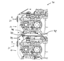
図1および図2は、製粉ローラ粉砕機のためのローラアセンブリ10の側面図を示す。ローラアセンブリ10は、2つの第1の軸受本体13によって保持されている第1のローラ11と、2つの第2の軸受本体14によって保持されている第2のローラ12とを含む。第2の軸受本体14は、枢動ボルト57を介して第1の軸受本体13上に枢動可能に支持されている。
1 and 2 show side views of a
図3a~図3cに示されている製粉ローラ粉砕機70は、機械台71と、2つのローラアセンブリ10とを有し、これら2つのローラアセンブリ10は、互いの上に、ひいては省スペースに配置されている。それぞれのローラアセンブリ10は、伝動機構43によって駆動可能であり、伝動機構43は、軸受ハウジング44を含み、軸受ハウジング44内には、入力軸(ここでは見えない)と、第1の出力軸46と、第2の出力軸47とが収容されている。入力軸と第1の出力軸46とは、互いに垂直に配置されていて、第1の出力軸46と第2の出力軸47とは、互いに平行に配置されている。入力軸と第1の出力軸46とは、傘歯車対(ここでは見えない)によって、互いに伝動可能に接続されていて、第1の出力軸46と第2の出力軸47とは、トルク伝達装置(同様に見えない)によって、互いに伝動可能に接続されている。第1の出力軸は、第1のローラ11に結合されていて、第2の出力軸47は、第2のローラ12に結合されている。伝動機構43の詳細な説明については、既に述べた国際特許出願第PCT/EP2018/061793号明細書を参照されたい。伝動機構43により、第2のローラ12を可動に取り付けることができる。
The milling
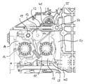
第1の軸受本体13はさらに、第1のストッパ本体17を有し、第1のストッパ本体17は、第1の回転軸線A1を中心にして回転可能であって、第1のストッパ面18を有する。第1のストッパ面18は、第1のストッパ本体17の、第1の回転軸線A1に対して偏心している円周面18によって形成されている。第2の軸受本体14は、第2のストッパ本体19を有し、第2のストッパ本体19は、第1の回転軸線A1に対して平行な第2の回転軸線A2を中心にして回転可能であって、第2のストッパ面20を有する。第2のストッパ面20は、第2のストッパ本体19の、第2の回転軸線A2に対して回転対称である円周面20によって形成されている。以下で説明するように、これら2つのストッパ面18,20は、当該ストッパ面18,20同士の接触がローラ11,12同士の接触を阻止するように、軸受本体13,14上に形成および配置されている。
The
図1は、ストッパ面18,20同士が互いに接触していない、ローラアセンブリ10の連動解除された位置を示す。機械台71の構成部分であって、かつここでは部分的にのみ図示されている緊締装置16により、第1のローラ11と第2のローラ12との間に形成される粉砕間隙を調整することができるように、第1の軸受本体13および第2の軸受本体14を互いに対して調整することができる。緊締装置16は、引っ張りアンカー51と、枢軸54を介して引っ張りアンカー51の上側端部67に枢動可能に取り付けられた引っ張りブッシュ55と、引っ張りブッシュ55内に部分的に収容されていて、かつ皿ばねアセンブリ41によって予荷重が加えられた引っ張りロッド52と、引っ張りアンカー51の下側端部68に結合されていて、かつ図4にのみ図示されているベローズシリンダ40とを含む。引っ張りロッド52は、第2の軸受本体14に配置された連結装置66によって、第2の軸受本体14に連結されている。引っ張りアンカー51は、ローラアセンブリ10が組み付けられている限り、支持点75において第1の軸受本体13上で支持されている。
FIG. 1 shows a disengaged position of the
図4は、ローラアセンブリ10を有する製粉ローラ粉砕機70の側面図を示す。ベローズシリンダ40を作動させることにより、引っ張りアンカー51の下側端部68が、第1の軸受本体13に押し付けられて、第1の軸受本体13上で支持され、その結果、ローラアセンブリ10に作用している全体の回転モーメントが減少する。ここで、引っ張りアンカー51は、支持点75を中心にして枢動し、これにより、引っ張りブッシュ55および引っ張りロッド52を引っ張り、ひいては、連結装置66を介して第2の軸受本体14を引っ張る。このようにして、第1の軸受本体13および第2の軸受本体14には、第1のローラ11と第2のローラ12とが互いに向かって押し付けられるように、互いに締め付け力が加えられる。
FIG. 4 shows a side view of the milling
ベローズシリンダ40を介して支承することにより、過負荷保護がもたらされる。過負荷状態(例えば、粉砕間隙に異物が入ったとき)において即座に負荷を緩和することができるようにするために、ベローズシリンダは、排気弁と接続しており、この排気弁は、ベローズシリンダ内に存在する圧力を、排気弁の開放によって急速に低減させることができるように十分に寸法設定されている。排気弁が開放しない場合、その結果として力の増加も生じるであろうが、この力の増加は、ばねアセンブリしか存在しない場合よりも格段に小さいものであろう。
By bearing via the
図2に示されているローラアセンブリ10の押し込まれた位置は、ストッパ面18,20同士が互いに接触したときに達成される。粉砕間隙内に生じている力が変化した場合には、軸受本体13と14との間の締め付け力のみが変化し、軸受本体13と14との間の相対位置は変化しない。第1のストッパ本体17の回転位置が、粉砕間隙の最小幅を決定する。
The pushed position of the
粉砕間隙の幅を大まかに設定できるようにするために、第1のストッパ本体17の第1の回転軸線A1と、第2のストッパ本体19の第2の回転軸線A2とは、変位可能に配置されており、正確に言えば、回転軸線A1,A2に対して垂直な方向に変位可能に配置されている。
The first rotation axis A1 of the
ローラアセンブリ10はさらに、粉砕間隙の幅を微調整するために、ハンドル軸線Hを中心にして回転することができるハンドル21を有している。ハンドル21は、図5に示されているハンドル伝動機構22を介して第1のストッパ本体17に結合されている。ハンドル21は、当該ハンドル21の回転が第1のストッパ本体17の回転を引き起こすように構成されている。したがって、ハンドル21に対する比較的小さなトルクを、第1のストッパ本体17における大きなトルクに変換することが可能である。前述の目的のために、ハンドル伝動機構22は、高い効率と、小さいバックラッシュとを有する。
The
ローラアセンブリ10はさらに、ハンドル21の位置を示すための、図6に詳細に示されている位置インジケータ26を有する。位置インジケータ26は、位置インジケータハウジング27と、インジケータ要素28とを含み、インジケータ要素28は、位置インジケータハウジング27に対してハンドル回転軸線Hに沿って移動可能である。インジケータ要素28には、少なくとも1つの位置インジケータばね29によって、位置インジケータハウジング27に対してハンドル回転軸線Hの方向に予荷重が加えられているか、または予荷重を加えることができ、インジケータ要素28は、位置インジケータばね29によってもたらされた予荷重を克服した場合にのみ、ハンドル回転軸線Hを中心にして回転することができるようになっている。このことは、インジケータ要素28および位置インジケータハウジング27における形状結合要素53によって実施される。
The
ローラ11と12との間に生じる半径方向の力を検出するために、ローラアセンブリ10は、第1の力センサ24および第2の力センサ25を有する力測定装置を含む。第1の力センサ24は、緊締装置16に組み込まれており、すなわち、引っ張りアンカー51と引っ張りロッド52との間に配設された枢軸54の領域に組み込まれており、第2の力センサ25は、第2のストッパ本体19上に配置されている(図7を参照)。このようにして、第1の軸受本体13と第2の軸受本体14を互いに押し付けている第1の力を検出するために、第1のセンサ24を使用することができ、第1のストッパ本体17と第2のストッパ本体19との間に作用する第2の力を検出するために、第2のセンサ25を使用することができる。これらの力から、ローラ11,12同士の間に作用する力を計算によって決定することができる。
To detect the radial force generated between the
図8は、どのようにして第2の軸受本体14が、枢動ボルト57を介して第1の軸受本体13上で枢動可能に支持されているかを詳細に示す。第1の軸受本体13は、それぞれくさび39を含み、このくさび39を貫通して調整ねじ56が案内されている。調整ねじ56の回転は、水平の第1の方向R1におけるくさび39の変位をもたらし、したがって、第1の方向R1に対して垂直である第2の方向R2における枢動ボルト57および第2の軸受本体14の変位をもたらす。このようにして、第2の軸受本体14を、第1の軸受本体13に対して個別に調整することができ、これにより、ローラ軸線を傾けることができる。
FIG. 8 shows in detail how the
図9および図10は、転がり軸受58と、転がり軸受58のシーリング(封止)とを詳細に示す。第2のローラ12のローラ軸部33は、内レース(内輪)59と、複数の転動体60と、外レース(外輪)61とによって支持されている。第2のローラ12の軸線方向には、内側軸受カバー62および外側軸受カバー63が配置されており、内側軸受カバー62および外側軸受カバー63は、各自の内側34に、シール(ここには図示されていない)を収容するための、ローラ軸部33の周りに延在する溝64と、潤滑剤のための案内溝35とを有する。潤滑剤の排出を支援する段部65も設けられている。外側軸受カバー63の案内溝35は、出口開口部36に接続されており、この出口開口部36を介して、外側軸受カバー63の案内溝35から潤滑剤を排出することができる。出口開口部36の下には、桶37の形態の、潤滑剤を収集するための収集装置37が配置されている。過剰潤滑を防止するために、内部と案内溝35との間に接続孔(図示せず)が設けられており、これにより、この接続孔を通して過剰なグリースを漏出させることができる。これによって、製粉ローラ粉砕機70を衛生的に動作させることができる。
9 and 10 show in detail the rolling
図11に示されているように、ローラアセンブリ10は、複数のころ31を備える組み込まれた転動装置30を有する。ころ31は、ローラアセンブリ10を水平な基礎(ここには図示されていない)上に配置することができるように、かつローラアセンブリ10がころ31によってこの水平な基礎上を移動することができるように、ローラアセンブリ10に配設されている。図12に示されているように、製粉ローラ粉砕機70の機械台71は、レール72を有し、ローラアセンブリ10の取り付け中および/または取り外し中には、このレール72上をローラアセンブリ10のころ31が移動することができる。ローラアセンブリ10はさらに、前側の接触面76(図8を参照)および後側の接触面42を有し、機械台71は、対応する相手側接触面73を有する。接触面42,76と相手側接触面73とは、ローラアセンブリ10が取り付けられた位置では、接触面42,76と相手側接触面73との間の形状結合による係合により、ころ31がレール72上に載置されることのないように、互いに対して、かつレール72に対して調整されている。
As shown in FIG. 11, the
Claims (17)
当該ローラアセンブリ(10)は、
少なくとも1つの第1の軸受本体(13)によって保持されている第1のローラ(11)と、
少なくとも1つの第2の軸受本体(14)によって保持されている第2のローラ(12)と
を含み、
前記第1のローラ(11)と前記第2のローラ(12)との間に形成される粉砕間隙を調整することができるように、前記第1の軸受本体(13)および前記第2の軸受本体(14)を互いに対して位置調節することができ、
前記第1の軸受本体(13)および前記第2の軸受本体(14)には、緊締装置(16)によって、前記第1のローラ(11)と前記第2のローラ(12)とが互いに向かって押し付けられるように、互いに予荷重を加えることができる、
ローラアセンブリ(10)において、
・前記第1の軸受本体(13)は、第1のストッパ面(18)を備える少なくとも1つの第1のストッパ本体(17)を有し、
前記第2の軸受本体(14)は、第2のストッパ面(20)を備える少なくとも1つの第2のストッパ本体(19)を有し、
・前記ストッパ面(18,20)は、当該ストッパ面(18,20)同士の接触が前記ローラ(11,12)同士の接触を阻止するように、前記軸受本体(13,14)上に形成および配置されているか、または配置可能であり、
・前記第1のストッパ本体(17)は、第1の回転軸線(A1)を中心にして回転可能であり、
前記第1のストッパ面(18)は、前記第1のストッパ本体(17)の、前記第1の回転軸線(A1)に対して偏心している円周面(18)によって形成されており、
その結果、前記第1のストッパ本体(17)の回転位置が、前記粉砕間隙の最小幅を決定するようになっている
ことを特徴とする、ローラアセンブリ(10)。 A roller assembly (10) for the crusher (70),
The roller assembly (10) is
With the first roller (11) held by at least one first bearing body (13),
Including a second roller (12) held by at least one second bearing body (14).
The first bearing body (13) and the second bearing so that the crushing gap formed between the first roller (11) and the second roller (12) can be adjusted. The main body (14) can be adjusted in position with respect to each other,
The first roller (11) and the second roller (12) face each other on the first bearing body (13) and the second bearing body (14) by a tightening device (16). Can be preloaded with each other so that they are pressed against each other,
In the roller assembly (10)
The first bearing body (13) has at least one first stopper body (17) provided with a first stopper surface (18).
The second bearing body (14) has at least one second stopper body (19) provided with a second stopper surface (20).
The stopper surface (18, 20) is formed on the bearing body (13, 14) so that the contact between the stopper surfaces (18, 20) prevents the contact between the rollers (11, 12). And placed or deployable,
The first stopper body (17) can rotate about the first rotation axis (A1), and can rotate around the first rotation axis (A1).
The first stopper surface (18) is formed by a circumferential surface (18) of the first stopper body (17) that is eccentric with respect to the first rotation axis (A1).
As a result, the roller assembly (10) is characterized in that the rotational position of the first stopper body (17) determines the minimum width of the crushing gap.
前記第2のストッパ面(20)は、前記第2のストッパ本体(19)の、前記第2の回転軸線(A2)に対して回転対称である円周面(20)によって形成されている、
請求項1記載のローラアセンブリ(10)。 The second stopper body (19) can rotate about a second rotation axis (A2) parallel to the first rotation axis (A1).
The second stopper surface (20) is formed by a circumferential surface (20) of the second stopper body (19) that is rotationally symmetric with respect to the second rotation axis (A2).
The roller assembly (10) according to claim 1.
請求項1または2記載のローラアセンブリ(10)。 The first rotation axis (A1) of the first stopper body (17) and / or the second rotation axis (A2) of the second stopper body (19) is particularly the first rotation axis. It is arranged so that it can be displaced in the direction perpendicular to (A1).
The roller assembly (10) according to claim 1 or 2.
前記ハンドル(21)は、ハンドル回転軸線(H)を中心にして回転可能であって、かつ当該ハンドル(21)の回転が前記第1のストッパ本体(17)の回転を引き起こすように、ハンドル伝動機構(22)を介して前記第1のストッパ本体(17)に連結されている、
請求項1から3までのいずれか1項記載のローラアセンブリ(10)。 The roller assembly (10) has a handle (21).
The handle (21) is rotatable about the handle rotation axis (H), and the handle is transmitted so that the rotation of the handle (21) causes the rotation of the first stopper body (17). It is connected to the first stopper body (17) via a mechanism (22).
The roller assembly (10) according to any one of claims 1 to 3.
・前記第1の軸受本体(13)および前記第2の軸受本体(14)に互いに予荷重を加えている第1の力を直接的または間接的に検出するための第1のセンサ(24)と、
・前記第1のストッパ本体(17)と前記第2のストッパ本体(19)との間に作用する第2の力を直接的または間接的に検出するための第2のセンサ(25)と
を含む、
請求項1から4までのいずれか1項記載のローラアセンブリ(10)。 The roller assembly (10) has a force measuring device, and the force measuring device is a force measuring device.
A first sensor (24) for directly or indirectly detecting a first force that preloads the first bearing body (13) and the second bearing body (14). When,
A second sensor (25) for directly or indirectly detecting a second force acting between the first stopper body (17) and the second stopper body (19). include,
The roller assembly (10) according to any one of claims 1 to 4.
当該ローラアセンブリ(10)は、
第1のローラ(11)および第2のローラ(12)と、
ハンドル回転軸線(H)を中心にして回転可能であって、かつ前記第1のローラ(11)と前記第2のローラ(12)との間に形成された粉砕間隙を調節することができるハンドル(21)と
を含み、
特に、前記ローラアセンブリ(10)は、請求項4記載のローラアセンブリ(10)である、
ローラアセンブリ(10)において、
前記ローラアセンブリ(10)は、前記ハンドル(21)の位置を示すための位置インジケータ(26)を有し、
前記位置インジケータ(26)は、位置インジケータハウジング(27)と、インジケータ要素(28)とを含み、
前記インジケータ要素(28)は、前記位置インジケータハウジング(27)に対して前記ハンドル回転軸線(H)に沿って移動可能であり、
前記インジケータ要素(28)には、位置インジケータばね(29)によって、前記位置インジケータハウジング(27)に対して前記ハンドル回転軸線(H)の方向に予荷重が加えられているか、または予荷重を加えることができ、
前記インジケータ要素(28)が、前記位置インジケータばね(29)によってもたらされた前記予荷重を克服した場合にのみ、前記ハンドル回転軸線(H)を中心にして回転することができるようになっている、
ローラアセンブリ(10)。 A roller assembly (10) for the crusher (70),
The roller assembly (10) is
With the first roller (11) and the second roller (12),
A handle that can rotate around the handle rotation axis (H) and can adjust the crushing gap formed between the first roller (11) and the second roller (12). Including (21)
In particular, the roller assembly (10) is the roller assembly (10) according to claim 4.
In the roller assembly (10)
The roller assembly (10) has a position indicator (26) for indicating the position of the handle (21).
The position indicator (26) includes a position indicator housing (27) and an indicator element (28).
The indicator element (28) is movable with respect to the position indicator housing (27) along the handle rotation axis (H).
The indicator element (28) is preloaded or preloaded in the direction of the handle rotation axis (H) with respect to the position indicator housing (27) by the position indicator spring (29). It is possible,
The indicator element (28) can only rotate about the handle rotation axis (H) if it overcomes the preload provided by the position indicator spring (29). Yes,
Roller assembly (10).
前記少なくとも1つのころ(31)は、前記ローラアセンブリ(10)を水平な基礎上に配置することができるように、かつ前記ローラアセンブリ(10)が前記少なくとも1つのころ(31)によって前記水平な基礎上を移動することができるように、前記ローラアセンブリ(10)に配置されているか、または配置可能である、
請求項1から6までのいずれか1項記載のローラアセンブリ(10)。 The roller assembly (10) has a built-in rolling device (30) with at least one roller (31).
The at least one roller (31) is such that the roller assembly (10) can be placed on a horizontal foundation, and the roller assembly (10) is said horizontal by the at least one roller (31). It is arranged or can be arranged in the roller assembly (10) so that it can move on the foundation.
The roller assembly (10) according to any one of claims 1 to 6.
前記転がり軸受(58)の軸受カバー(63)は、自身の内側(34)に、潤滑剤のための案内溝(35)を有し、
前記案内溝(35)は、前記ローラ軸部(33)の周りに延在していて、かつ出口開口部(36)に接続されており、前記出口開口部(36)を介して前記案内溝(35)から前記潤滑剤を排出することができる、
請求項1から7までのいずれか1項記載のローラアセンブリ(10)。 At least one of the bearing bodies (13, 14) has a rolling bearing (58) that supports the roller shaft portion (33) of one of the rollers (11, 12). Have and
The bearing cover (63) of the rolling bearing (58) has a guide groove (35) for a lubricant on the inside (34) of the rolling bearing (58).
The guide groove (35) extends around the roller shaft portion (33) and is connected to the outlet opening (36), and the guide groove (35) is connected to the outlet opening (36). The lubricant can be discharged from (35).
The roller assembly (10) according to any one of claims 1 to 7.
前記第2のローラ(12)は、2つの第2の軸受本体(14)によって保持されており、
前記第1の軸受本体(13)同士は、互いに独立して位置調節可能であり、かつ/または
前記第2の軸受本体(14)同士は、互いに独立して位置調節可能である、
請求項1から8までのいずれか1項記載のローラアセンブリ(10)。 The first roller (11) is held by two first bearing bodies (13).
The second roller (12) is held by two second bearing bodies (14).
The positions of the first bearing bodies (13) can be adjusted independently of each other, and / or the positions of the second bearing bodies (14) can be adjusted independently of each other.
The roller assembly (10) according to any one of claims 1 to 8.
当該粉砕装置(70)は、
機械台(71)と、
前記機械台(71)に装着されているか、または装着可能である、請求項1から9までのいずれか1項記載の少なくとも1つのローラアセンブリ(10)と
を含む、粉砕装置(70)。 A crusher (70), especially a milling roller crusher (70).
The crushing device (70) is
Machine stand (71) and
A crushing apparatus (70) comprising at least one roller assembly (10) according to any one of claims 1 to 9, which is mounted on or mountable on the machine base (71).
前記ローラアセンブリ(10)は、前記ローラアセンブリ(10)を前記緊締装置(16)に解離可能に結合するために、特に前記第2の軸受本体(14)に配置された連結装置(66)を有している、
請求項10記載の粉砕装置(70)。 The machine base (71) has a tightening device (16).
The roller assembly (10) particularly comprises a coupling device (66) disposed in the second bearing body (14) in order to dissociably couple the roller assembly (10) to the tightening device (16). Have,
The crushing apparatus (70) according to claim 10.
請求項10または11記載の粉砕装置(70)。 The tightening device (16) has a cylinder (40), in particular a bellows cylinder (40).
The crushing apparatus (70) according to claim 10 or 11.
請求項10から12までのいずれか1項記載の粉砕装置(70)。 The tightening device (16) has at least one preloaded spring (41), the at least one spring (41) being specifically connected in series with the cylinder (40).
The crushing apparatus (70) according to any one of claims 10 to 12.
当該粉砕装置(70)は、
機械台(71)と、
第1のローラ(11)および第2のローラ(12)を有していて、かつ前記機械台(71)に装着されているか、または装着可能である少なくとも1つのローラアセンブリ(10)と
を含み、
特に、前記粉砕装置(70)は、請求項10から13までのいずれか1項記載の粉砕装置(70)であり、
前記ローラアセンブリは、少なくとも1つのころ(31)を備える組み込まれた転動装置(30)を有し、
前記少なくとも1つのころ(31)は、前記ローラアセンブリ(10)を水平な基礎上に配置することができるように、かつ前記ローラアセンブリ(10)が前記少なくとも1つのころ(31)によって前記水平な基礎上を移動することができるように、前記ローラアセンブリ(10)に配置されているか、または配置可能である、
粉砕装置(70)において、
前記機械台(71)は、少なくとも1つのレール(72)を有し、
前記ローラアセンブリ(10)の取り付け中および/または取り外し中には、前記少なくとも1つのレール(72)上を前記ローラアセンブリ(10)の前記少なくとも1つのころ(31)が転動することができ、
前記ローラアセンブリ(10)は、少なくとも1つの接触面(42,76)を有し、
前記機械台(71)は、少なくとも1つの相手側接触面(73)を有し、
前記接触面(42,76)と前記相手側接触面(73)とは、前記ローラアセンブリ(10)が取り付けられた位置では、前記少なくとも1つの接触面(42,76)と前記少なくとも1つの相手側接触面(73)との間の少なくとも1つの形状結合による係合により、前記ローラアセンブリ(10)の前記少なくとも1つのころ(31)が前記レール(72)上に載置されないように、互いに対して、かつ前記少なくとも1つのレール(72)に対して位置調整されている、
粉砕装置(70)。 A crusher (70), especially a milling roller crusher (70).
The crushing device (70) is
Machine stand (71) and
Includes at least one roller assembly (10) that has a first roller (11) and a second roller (12) and is mounted or mountable on the machine base (71). ,
In particular, the crushing device (70) is the crushing device (70) according to any one of claims 10 to 13.
The roller assembly has a built-in rolling device (30) with at least one roller (31).
The at least one roller (31) is such that the roller assembly (10) can be placed on a horizontal foundation, and the roller assembly (10) is said horizontal by the at least one roller (31). It is arranged or can be arranged in the roller assembly (10) so that it can move on the foundation.
In the crusher (70)
The machine base (71) has at least one rail (72).
During installation and / or removal of the roller assembly (10), the at least one roller (31) of the roller assembly (10) can roll on the at least one rail (72).
The roller assembly (10) has at least one contact surface (42,76).
The machine base (71) has at least one mating surface (73).
The contact surface (42,76) and the mating side contact surface (73) are the at least one contact surface (42,76) and the at least one mating surface at the position where the roller assembly (10) is attached. Engagement by at least one shape coupling with the side contact surface (73) prevents the at least one roller (31) of the roller assembly (10) from resting on the rail (72). On the other hand, the position is adjusted with respect to the at least one rail (72).
Crushing device (70).
前記ローラ(11,12)同士の間に作用する前記力を、センサ(24,25)によって検出された力から計算するステップを含む、
方法。 A method for detecting a radial force acting between the rollers (11, 12) of the roller assembly (10) according to claim 5.
A step of calculating the force acting between the rollers (11, 12) from the force detected by the sensor (24, 25).
Method.
前記第1の軸受本体(13)および前記第2の軸受本体(14)に、前記緊締装置(16)によって、前記第1のローラ(11)と前記第2のローラ(12)とが互いに向かって押し付けられるように、互いに予荷重を加えるステップを含む、
方法。 A method for operating the roller assembly (10) according to any one of claims 1 to 9.
The first roller (11) and the second roller (12) face each other on the first bearing body (13) and the second bearing body (14) by the tightening device (16). Includes steps to preload each other so that they are pressed against each other,
Method.
粉砕間隙の最小幅を設定するために、前記第1のストッパ本体(17)を、前記第1の回転軸線(A1)を中心にして回転させるさらなるステップ
を含む、請求項16記載の方法。 The method is
16. The method of claim 16, comprising a further step of rotating the first stopper body (17) about the first rotation axis (A1) in order to set a minimum width of the crushing gap.
Applications Claiming Priority (4)
| Application Number | Priority Date | Filing Date | Title |
|---|---|---|---|
| EP18174570.4A EP3575001B3 (en) | 2018-05-28 | 2018-05-28 | Roller packages for milling devices, milling devices and method |
| EP18174570.4 | 2018-05-28 | ||
| JP2020566760A JP6974634B2 (en) | 2018-05-28 | 2019-05-28 | Roller assembly, crusher, and method for crusher |
| PCT/EP2019/063716 WO2019229014A2 (en) | 2018-05-28 | 2019-05-28 | Roller groups for grinding devices, grinding devices, and methods |
Related Parent Applications (1)
| Application Number | Title | Priority Date | Filing Date |
|---|---|---|---|
| JP2020566760A Division JP6974634B2 (en) | 2018-05-28 | 2019-05-28 | Roller assembly, crusher, and method for crusher |
Publications (2)
| Publication Number | Publication Date |
|---|---|
| JP2022017488A true JP2022017488A (en) | 2022-01-25 |
| JP7250888B2 JP7250888B2 (en) | 2023-04-03 |
Family
ID=62455371
Family Applications (3)
| Application Number | Title | Priority Date | Filing Date |
|---|---|---|---|
| JP2020566760A Active JP6974634B2 (en) | 2018-05-28 | 2019-05-28 | Roller assembly, crusher, and method for crusher |
| JP2021180441A Active JP7250888B2 (en) | 2018-05-28 | 2021-11-04 | Roller assembly, crusher, and method for crusher |
| JP2021180440A Active JP7147034B2 (en) | 2018-05-28 | 2021-11-04 | Roller assembly, crusher, and method for crusher |
Family Applications Before (1)
| Application Number | Title | Priority Date | Filing Date |
|---|---|---|---|
| JP2020566760A Active JP6974634B2 (en) | 2018-05-28 | 2019-05-28 | Roller assembly, crusher, and method for crusher |
Family Applications After (1)
| Application Number | Title | Priority Date | Filing Date |
|---|---|---|---|
| JP2021180440A Active JP7147034B2 (en) | 2018-05-28 | 2021-11-04 | Roller assembly, crusher, and method for crusher |
Country Status (12)
| Country | Link |
|---|---|
| US (3) | US11266993B2 (en) |
| EP (3) | EP3575001B3 (en) |
| JP (3) | JP6974634B2 (en) |
| KR (3) | KR102321211B1 (en) |
| CN (3) | CN114011508B (en) |
| AU (3) | AU2019275986B2 (en) |
| BR (1) | BR112020023619B1 (en) |
| CA (3) | CA3189974A1 (en) |
| ES (2) | ES2831502T3 (en) |
| MX (3) | MX2020012808A (en) |
| RU (1) | RU2754042C1 (en) |
| WO (1) | WO2019229014A2 (en) |
Families Citing this family (4)
| Publication number | Priority date | Publication date | Assignee | Title |
|---|---|---|---|---|
| EP3575001B3 (en) * | 2018-05-28 | 2022-09-14 | Bühler AG | Roller packages for milling devices, milling devices and method |
| CN111729723A (en) * | 2020-07-02 | 2020-10-02 | 江西金穗丰糖业有限公司 | A raw materials processingequipment for maltose preparation |
| CN112169969B (en) * | 2020-08-06 | 2021-10-22 | 宁化县腾丰香料厂 | Double-layer type crushing device for production of biomass pellet fuel raw materials |
| EP4000734A1 (en) | 2020-11-20 | 2022-05-25 | Bühler AG | Roller mill with improved product collection |
Citations (7)
| Publication number | Priority date | Publication date | Assignee | Title |
|---|---|---|---|---|
| DE524055C (en) * | 1931-05-01 | Ratzinger & Weidenkaff Maschf | Roller mill for grinding sand, ores or the like. | |
| US5018960A (en) * | 1990-01-12 | 1991-05-28 | Wenger Manufacturing, Inc. | Flaking roll apparatus |
| JP2000510388A (en) * | 1997-04-11 | 2000-08-15 | アントン・シュタイネッカー・マシネンファブリーク・ゲゼルシャフト・ミット・ベシュレンクテル・ハフツング | Grinding gap adjustment |
| EP1201308A1 (en) * | 2000-10-25 | 2002-05-02 | OCRIM S.p.A. | Cereal milling device |
| DE10125378A1 (en) * | 2001-05-23 | 2002-11-28 | Voith Paper Patent Gmbh | Distance between paper coating parallel rollers regulated by reference to calibrated target gap space/pressure force characteristic relationship |
| JP2017166072A (en) * | 2017-05-15 | 2017-09-21 | エーシーエム リサーチ (シャンハイ) インコーポレーテッド | Device and method for plating and/or polishing wafer |
| JP6974634B2 (en) * | 2018-05-28 | 2021-12-01 | ビューラー・アクチエンゲゼルシャフトBuehler AG | Roller assembly, crusher, and method for crusher |
Family Cites Families (48)
| Publication number | Priority date | Publication date | Assignee | Title |
|---|---|---|---|---|
| US236104A (en) * | 1880-12-28 | Grinding-mill | ||
| US1349221A (en) * | 1918-06-17 | 1920-08-10 | Nolen Robert Rufus | Mill |
| GB218752A (en) * | 1923-04-13 | 1924-07-14 | John Rowland Torrance | Adjusting device for the rolls of grinding, crushing, pulverising, and the like and other machinery |
| DE595934C (en) | 1932-05-04 | 1934-04-24 | Schneider Jaquet & Cie Sa | Device for regulating the contact pressure of grinding rollers |
| DE597775C (en) | 1932-08-20 | 1934-06-02 | Schneider Jaquet & Cie Sa | Device for regulating the contact pressure of grinding rollers |
| US2080364A (en) * | 1933-04-07 | 1937-05-11 | Baker Perkins Co Inc | Chocolate and like refiner roll machine |
| GB455244A (en) * | 1935-06-29 | 1936-10-16 | Henry Edward Cox | Improvements in and connected with mills for mixing, grinding, refining, and other processes |
| US2141647A (en) * | 1936-07-25 | 1938-12-27 | Simon Ltd Henry | Milling machine for grain |
| CH300578A (en) * | 1949-09-10 | 1954-08-15 | Miag Vertriebs Gmbh | Device for displaying the size of the grinding gap in roller mills. |
| CH333567A (en) * | 1954-04-05 | 1958-10-31 | Siemens Ag | Load indicator on an electricity meter |
| US3174696A (en) * | 1962-05-11 | 1965-03-23 | Deere & Co | Roller mill |
| GB1192732A (en) * | 1966-08-31 | 1970-05-20 | Rose Downs & Thompson Ltd | Roll Gap Control |
| GB1164655A (en) * | 1967-07-24 | 1969-09-17 | Schwermaschb Karl Liebknecht | Improvements in or relating to Devices for the Remote Operation of Diesel Engines and Shiftable Gearboxes |
| DE1900879A1 (en) * | 1969-01-09 | 1970-08-20 | Ante Raguz | Handwheel with position indicator |
| GB1320343A (en) * | 1970-03-10 | 1973-06-13 | Alvan Blanch Dev Co Ltd | Attachment to be fitted to a roller mill to increase or decrease the nip between a pair of rollers of the roller mill |
| AR204048A1 (en) * | 1974-08-27 | 1975-11-12 | Isringhausen Geb | POSITION INDICATOR FOR ROTATING SPINDLES |
| DE2539153C2 (en) * | 1975-09-03 | 1985-03-28 | Bühler-Miag GmbH, 3300 Braunschweig | Roller mill for grinding cereals, paint, chocolate or similar goods |
| US4339083A (en) * | 1976-07-16 | 1982-07-13 | Gebrueder Buehler Ag | Apparatus for the grinding of cereal |
| CH619157A5 (en) * | 1976-07-16 | 1980-09-15 | Buehler Ag Geb | |
| SU886977A1 (en) * | 1978-10-04 | 1981-12-07 | Институт Физико-Химических Основ Переработки Минерального Сырья Со Ан Ссср | Planetary mill |
| EG13919A (en) * | 1979-01-23 | 1983-03-31 | Satake Eng Co Ltd | Automatic control system for hilling machine |
| US4377110A (en) * | 1980-12-11 | 1983-03-22 | Iseki & Co., Ltd. | Auto-control equipment of hull-removing roll in rice-hulling machines |
| US4608007A (en) * | 1983-05-13 | 1986-08-26 | Wood Errol A | Oat crimper |
| IT1163626B (en) * | 1983-06-29 | 1987-04-08 | Carle & Montanari Spa | ADJUSTABLE WORKING REFINER FOR CHOCOLATE |
| DE8509180U1 (en) * | 1985-03-27 | 1985-06-20 | Hoesch Maschinenfabrik Deutschland Ag, 4600 Dortmund | Underfloor wheelset lathe for reprofiling the wheel tire outlines of railway wheelsets |
| RU2015728C1 (en) * | 1992-01-14 | 1994-07-15 | Геннадий Михайлович Яковлев | Grinding machine |
| DE4208490A1 (en) * | 1992-03-17 | 1993-09-23 | Wirth Muehlenbau Dresden Gmbh | Maintaining constant nip in rolls of rolling machine - involves moving adjacent ends of both rolls of pair in opposing directions away from common starting plane |
| EP0619871B1 (en) * | 1992-10-30 | 1996-09-18 | Bühler Ag | Method of measuring the thickness of a layer, and a device for carrying out the method |
| GB2293990A (en) * | 1994-10-11 | 1996-04-17 | Satake Uk Ltd | A cereal milling machine |
| US5673764A (en) | 1995-04-14 | 1997-10-07 | Falgout, Sr.; Thomas E. | Drill string orienting motor |
| JP2002525506A (en) * | 1998-09-11 | 2002-08-13 | シュクラ−ゲレテバウ アクチェンゲゼルシャフト | Brake drive |
| JP2004527373A (en) | 2001-05-23 | 2004-09-09 | ボイス ペ−パ− パテント ゲ−エムベ−ハ− | Apparatus, method and arrangement for pressing two axially parallel rollers which can approach each other in an apparatus for producing and / or processing a material web |
| RU31518U1 (en) * | 2002-05-28 | 2003-08-20 | Титомир Александр Козмович | Device for grinding material |
| DE10316691A1 (en) * | 2003-04-10 | 2004-10-28 | Bühler AG | Cylinder mill for milling or crushing grain has one frame support on one end guided by double cone, and at other end is fixed on base frame by clamping jaw, with mating component installed on base frame below end facing clamping jaw |
| DE202005014333U1 (en) * | 2005-09-09 | 2005-11-10 | Huppmann Ag | Modular wet pellet grinder has squashing roller module comprised of at least two squashing rollers and detachably mounted in module rack |
| CN201030319Y (en) * | 2007-05-08 | 2008-03-05 | 遂宁华能机械有限公司 | Multi-purpose crusher |
| TR200704949U (en) | 2007-07-16 | 2007-08-21 | Yükseli̇ş Maki̇na San. Ti̇c.A. Ş. | Bearing package with eccentric bushing and moment arm. |
| CN201322888Y (en) * | 2008-12-23 | 2009-10-07 | 天津精通控制仪表技术有限公司 | Side mounted hand-operating mechanism |
| US9180507B2 (en) * | 2009-12-28 | 2015-11-10 | Nakata Manufacturing Co., Ltd. | Turk's head stand |
| WO2012056461A1 (en) | 2010-10-27 | 2012-05-03 | Buhler (India) Pvt. Ltd | Abrasive roll assembly |
| JP2014050844A (en) | 2011-02-28 | 2014-03-20 | Sintokogio Ltd | Briquetting machine |
| DE102012100077A1 (en) * | 2012-01-05 | 2013-07-11 | Siko Gmbh | Handwheel for adjusting and/or positioning elements at machine and/or system in industrial area, has fixing device designed as pressure screw and provided for radially locking display, where handwheel forms form-fit connection with display |
| US9579703B2 (en) * | 2013-10-02 | 2017-02-28 | Fives Bronx, Inc. | Roll change apparatus |
| KR101566895B1 (en) * | 2015-05-20 | 2015-11-09 | 충청환경산업 주식회사 | Roll crusher with clearance adjusting apparatus |
| CN205109724U (en) * | 2015-10-27 | 2016-03-30 | 湖南卓迪机械有限公司 | Machine is broken up in roll -type breakage |
| CN205965983U (en) * | 2016-07-08 | 2017-02-22 | 江阴华理防腐涂料有限公司 | Three -roller grinding mill |
| ES2755484T3 (en) | 2017-05-09 | 2020-04-22 | Buehler Ag | Feed and feed roller mill with one gear |
| CN107081183A (en) * | 2017-06-15 | 2017-08-22 | 江西省石城县矿山机械厂 | A kind of modified double-roll crusher |
-
2018
- 2018-05-28 EP EP18174570.4A patent/EP3575001B3/en active Active
- 2018-05-28 ES ES19184071T patent/ES2831502T3/en active Active
- 2018-05-28 EP EP19184069.3A patent/EP3597300B1/en active Active
- 2018-05-28 EP EP19184071.9A patent/EP3597301B1/en active Active
- 2018-05-28 ES ES18174570T patent/ES2829098T7/en active Active
-
2019
- 2019-05-28 WO PCT/EP2019/063716 patent/WO2019229014A2/en active Application Filing
- 2019-05-28 JP JP2020566760A patent/JP6974634B2/en active Active
- 2019-05-28 CN CN202111314021.7A patent/CN114011508B/en active Active
- 2019-05-28 CA CA3189974A patent/CA3189974A1/en active Pending
- 2019-05-28 CN CN202111314110.1A patent/CN114011509B/en active Active
- 2019-05-28 BR BR112020023619-5A patent/BR112020023619B1/en active IP Right Grant
- 2019-05-28 CN CN201980046429.5A patent/CN112423888B/en active Active
- 2019-05-28 RU RU2020142853A patent/RU2754042C1/en active
- 2019-05-28 KR KR1020207037489A patent/KR102321211B1/en active IP Right Grant
- 2019-05-28 AU AU2019275986A patent/AU2019275986B2/en active Active
- 2019-05-28 CA CA3189961A patent/CA3189961A1/en active Pending
- 2019-05-28 US US17/058,892 patent/US11266993B2/en active Active
- 2019-05-28 CA CA3101679A patent/CA3101679C/en active Active
- 2019-05-28 KR KR1020217035023A patent/KR102600876B1/en active IP Right Grant
- 2019-05-28 MX MX2020012808A patent/MX2020012808A/en unknown
- 2019-05-28 KR KR1020217035029A patent/KR102602490B1/en active IP Right Grant
-
2020
- 2020-11-26 MX MX2021014078A patent/MX2021014078A/en unknown
- 2020-11-26 MX MX2021014077A patent/MX2021014077A/en unknown
-
2021
- 2021-11-04 JP JP2021180441A patent/JP7250888B2/en active Active
- 2021-11-04 JP JP2021180440A patent/JP7147034B2/en active Active
-
2022
- 2022-01-19 AU AU2022200350A patent/AU2022200350B2/en active Active
- 2022-01-19 AU AU2022200349A patent/AU2022200349B2/en active Active
- 2022-03-04 US US17/686,541 patent/US20220184627A1/en active Pending
- 2022-03-04 US US17/686,544 patent/US11925940B2/en active Active
Patent Citations (7)
| Publication number | Priority date | Publication date | Assignee | Title |
|---|---|---|---|---|
| DE524055C (en) * | 1931-05-01 | Ratzinger & Weidenkaff Maschf | Roller mill for grinding sand, ores or the like. | |
| US5018960A (en) * | 1990-01-12 | 1991-05-28 | Wenger Manufacturing, Inc. | Flaking roll apparatus |
| JP2000510388A (en) * | 1997-04-11 | 2000-08-15 | アントン・シュタイネッカー・マシネンファブリーク・ゲゼルシャフト・ミット・ベシュレンクテル・ハフツング | Grinding gap adjustment |
| EP1201308A1 (en) * | 2000-10-25 | 2002-05-02 | OCRIM S.p.A. | Cereal milling device |
| DE10125378A1 (en) * | 2001-05-23 | 2002-11-28 | Voith Paper Patent Gmbh | Distance between paper coating parallel rollers regulated by reference to calibrated target gap space/pressure force characteristic relationship |
| JP2017166072A (en) * | 2017-05-15 | 2017-09-21 | エーシーエム リサーチ (シャンハイ) インコーポレーテッド | Device and method for plating and/or polishing wafer |
| JP6974634B2 (en) * | 2018-05-28 | 2021-12-01 | ビューラー・アクチエンゲゼルシャフトBuehler AG | Roller assembly, crusher, and method for crusher |
Also Published As
Similar Documents
| Publication | Publication Date | Title |
|---|---|---|
| JP6974634B2 (en) | Roller assembly, crusher, and method for crusher | |
| KR101364474B1 (en) | Force monitor for pulverizer integral spring assembly | |
| AU2011361270B2 (en) | Briquette machine |
Legal Events
| Date | Code | Title | Description |
|---|---|---|---|
| A521 | Request for written amendment filed |
Free format text: JAPANESE INTERMEDIATE CODE: A523 Effective date: 20211111 |
|
| A621 | Written request for application examination |
Free format text: JAPANESE INTERMEDIATE CODE: A621 Effective date: 20211111 |
|
| A131 | Notification of reasons for refusal |
Free format text: JAPANESE INTERMEDIATE CODE: A131 Effective date: 20220830 |
|
| RD03 | Notification of appointment of power of attorney |
Free format text: JAPANESE INTERMEDIATE CODE: A7423 Effective date: 20220831 |
|
| A521 | Request for written amendment filed |
Free format text: JAPANESE INTERMEDIATE CODE: A523 Effective date: 20221129 |
|
| TRDD | Decision of grant or rejection written | ||
| A01 | Written decision to grant a patent or to grant a registration (utility model) |
Free format text: JAPANESE INTERMEDIATE CODE: A01 Effective date: 20230221 |
|
| A61 | First payment of annual fees (during grant procedure) |
Free format text: JAPANESE INTERMEDIATE CODE: A61 Effective date: 20230322 |
|
| R150 | Certificate of patent or registration of utility model |
Ref document number: 7250888 Country of ref document: JP Free format text: JAPANESE INTERMEDIATE CODE: R150 |