JP2021155152A - クレーン - Google Patents
クレーン Download PDFInfo
- Publication number
- JP2021155152A JP2021155152A JP2020055482A JP2020055482A JP2021155152A JP 2021155152 A JP2021155152 A JP 2021155152A JP 2020055482 A JP2020055482 A JP 2020055482A JP 2020055482 A JP2020055482 A JP 2020055482A JP 2021155152 A JP2021155152 A JP 2021155152A
- Authority
- JP
- Japan
- Prior art keywords
- hydraulic motor
- hydraulic
- valve
- crane
- rotation
- Prior art date
- Legal status (The legal status is an assumption and is not a legal conclusion. Google has not performed a legal analysis and makes no representation as to the accuracy of the status listed.)
- Granted
Links
- 238000001514 detection method Methods 0.000 claims description 5
- 238000004804 winding Methods 0.000 description 57
- 238000000034 method Methods 0.000 description 7
- 230000007423 decrease Effects 0.000 description 5
- 238000010586 diagram Methods 0.000 description 4
- 238000009429 electrical wiring Methods 0.000 description 4
- 238000009412 basement excavation Methods 0.000 description 3
- 230000001360 synchronised effect Effects 0.000 description 3
- 238000004891 communication Methods 0.000 description 2
- 230000000694 effects Effects 0.000 description 2
- 230000005281 excited state Effects 0.000 description 2
- 238000010276 construction Methods 0.000 description 1
- 238000006073 displacement reaction Methods 0.000 description 1
- 238000012986 modification Methods 0.000 description 1
- 230000004048 modification Effects 0.000 description 1
- 230000007935 neutral effect Effects 0.000 description 1
- 238000011144 upstream manufacturing Methods 0.000 description 1
Images


Landscapes
- Jib Cranes (AREA)
Abstract
Description
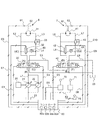
図4は、その他の実施形態に係るクレーンの油圧回路図である。図4に示すように、バイパス管路L4,L8に、それぞれスローリターンチェック弁(一方向絞り弁)80,81を設ける構成としても良い。スローリターンチェック弁80,81は、一方向の流れは自由流れを許容し、逆方向の流れは絞りで流量規制する。例えば油圧回路HC1において、巻上時は管路L2と管路L3との圧力差が大きいが、巻下時は管路L2と管路L3との圧力差が小さくなる。そこで、バイパス管路L4にスローリターンチェック弁80を設け、巻上時には自由にバイパス管路L4に圧油を流し、巻下時にはバイパス管路L4を流れる圧油を制限することで、より高精度な主巻ウインチ6と補巻ウインチ7との同調制御を実現できる。油圧回路HC2にスローリターンチェック弁81を設けた理由も同様である。
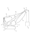
2 走行体
3 旋回装置
4 旋回体
5 ブーム
6 主巻ウインチ
7 補巻ウインチ
10,11 シーブ
12 主巻ロープ
13 補巻ロープ
16 バケット
20 エンジン
21,22 油圧ポンプ(油圧源)
23 タンク
30 方向制御弁(第1の方向制御弁)
31 油圧モータ(第1の油圧モータ)
32 電磁切換弁(第1の弁)
40 方向制御弁(第2の方向制御弁)
41 油圧モータ(第2の油圧モータ)
42 電磁切換弁(第2の弁)
50,51 ウインチドラム
60 コントローラ
70 主操作レバー(第1の操作装置)
71 補操作レバー(第2の操作装置)
75 開始ボタン
80,81 スローリターンチェック弁
L2,L3 管路(第1の入口側管路、第1の出口側管路)
L4 バイパス管路(第1のバイパス管路)
L6,L7 管路(第2の入口側管路、第2の出口側管路)
L8 バイパス管路(第2のバイパス管路)
Claims (7)
- 油圧源と、
前記油圧源からの圧油により駆動される第1の油圧モータと、
前記油圧源から供給される圧油が前記第1の油圧モータに向かって流れる第1の入口側管路と、
前記第1の油圧モータから排出された圧油が流れる第1の出口側管路と、
前記第1の入口側管路と前記第1の出口側管路とをつなぐ第1のバイパス管路と、
前記第1のバイパス管路に設けられた第1の弁と、
前記第1の油圧モータの回転数または回転量を直接的にまたは間接的に検出する第1の回転検出手段と、
前記油圧源からの圧油により駆動される第2の油圧モータと、
前記油圧源から供給される圧油が前記第2の油圧モータに向かって流れる第2の入口側管路と、
前記第2の油圧モータから排出された圧油が流れる第2の出口側管路と、
前記第2の入口側管路と前記第2の出口側管路とをつなぐ第2のバイパス管路と、
前記第2のバイパス管路に設けられた第2の弁と、
前記第2の油圧モータの回転数または回転量を直接的にまたは間接的に検出する第2の回転検出手段と、を備え、
前記第1の回転検出手段および前記第2の回転検出手段の検出結果に基づいて、前記第1の油圧モータと前記第2の油圧モータとを同調させるように、前記第1の弁および前記第2の弁のうち少なくとも一方の動作を制御する
ことを特徴とするクレーン。 - 請求項1に記載のクレーンにおいて、
前記油圧源と前記第1の油圧モータとの間に設けられ、前記油圧源から供給される圧油の流れ方向を制御する第1の方向制御弁と、
前記第1の方向制御弁を操作する第1の操作装置と、
前記油圧源と前記第2の油圧モータとの間に設けられ、前記油圧源から供給される圧油の流れ方向を制御する第2の方向制御弁と、
前記第2の方向制御弁を操作する第2の操作装置と、をさらに備え、
前記第1の操作装置および前記第2の操作装置からの操作信号が所定条件を満たすことに基づいて、前記第1の油圧モータと前記第2の油圧モータとを同調させる制御を開始することを特徴とするクレーン。 - 請求項2に記載のクレーンにおいて、
前記所定条件は、前記第1の操作装置および前記第2の操作装置が何れも同一方向に最大の操作量で操作されていることであることを特徴とするクレーン。 - 請求項2または3に記載のクレーンにおいて、
前記第1の弁は、前記第1の方向制御弁より最大流量が小さく、
前記第2の弁は、前記第2の方向制御弁より最大流量が小さい
ことを特徴とするクレーン。 - 請求項1〜4の何れか1項に記載のクレーンにおいて、
前記油圧源に対して、前記第1の油圧モータおよび前記第2の油圧モータが直列で接続されている
ことを特徴とするクレーン。 - 請求項1〜5の何れか1項に記載のクレーンにおいて、
前記第1のバイパス管路および前記第2のバイパス管路に、それぞれスローリターンチェック弁が設けられている
ことを特徴とするクレーン。 - 請求項1〜6の何れか1項に記載のクレーンにおいて、
前記第1の油圧モータと前記第2の油圧モータとを同調させる制御の開始からのそれぞれの総回転数または総回転量の差が第1の閾値以上になると、前記第1の弁および前記第2の弁のうち、前記総回転数または前記総回転量の大きい油圧モータに対応する弁を開け、前記差が前記第1の閾値よりも小さい第2の閾値以下になると、開けられた前記弁を閉める
ことを特徴とするクレーン。
Priority Applications (1)
| Application Number | Priority Date | Filing Date | Title |
|---|---|---|---|
| JP2020055482A JP7443120B2 (ja) | 2020-03-26 | 2020-03-26 | クレーン |
Applications Claiming Priority (1)
| Application Number | Priority Date | Filing Date | Title |
|---|---|---|---|
| JP2020055482A JP7443120B2 (ja) | 2020-03-26 | 2020-03-26 | クレーン |
Publications (2)
| Publication Number | Publication Date |
|---|---|
| JP2021155152A true JP2021155152A (ja) | 2021-10-07 |
| JP7443120B2 JP7443120B2 (ja) | 2024-03-05 |
Family
ID=77916655
Family Applications (1)
| Application Number | Title | Priority Date | Filing Date |
|---|---|---|---|
| JP2020055482A Active JP7443120B2 (ja) | 2020-03-26 | 2020-03-26 | クレーン |
Country Status (1)
| Country | Link |
|---|---|
| JP (1) | JP7443120B2 (ja) |
Citations (3)
| Publication number | Priority date | Publication date | Assignee | Title |
|---|---|---|---|---|
| US4305571A (en) * | 1977-02-01 | 1981-12-15 | Karmoy Mekaniske Verksted A/S | Means for regulating two trawl winches |
| JPS60162584U (ja) * | 1984-04-06 | 1985-10-29 | 石川島播磨重工業株式会社 | ダブルデツキクレ−ンの同期調整装置 |
| JP2017024834A (ja) * | 2015-07-17 | 2017-02-02 | コベルコ建機株式会社 | ウィンチの制御装置 |
-
2020
- 2020-03-26 JP JP2020055482A patent/JP7443120B2/ja active Active
Patent Citations (3)
| Publication number | Priority date | Publication date | Assignee | Title |
|---|---|---|---|---|
| US4305571A (en) * | 1977-02-01 | 1981-12-15 | Karmoy Mekaniske Verksted A/S | Means for regulating two trawl winches |
| JPS60162584U (ja) * | 1984-04-06 | 1985-10-29 | 石川島播磨重工業株式会社 | ダブルデツキクレ−ンの同期調整装置 |
| JP2017024834A (ja) * | 2015-07-17 | 2017-02-02 | コベルコ建機株式会社 | ウィンチの制御装置 |
Also Published As
| Publication number | Publication date |
|---|---|
| JP7443120B2 (ja) | 2024-03-05 |
Similar Documents
| Publication | Publication Date | Title |
|---|---|---|
| JP7261894B2 (ja) | 電動式油圧作業機械 | |
| KR20010034403A (ko) | 선회제어장치 | |
| JP5669264B2 (ja) | 作業用油圧制御装置 | |
| US20190194908A1 (en) | Construction Machine | |
| JP7433100B2 (ja) | 作業機械の油圧駆動装置 | |
| EP3730446B1 (en) | Crane | |
| JPH0741287A (ja) | クレーンのブーム起伏および巻上制御装置 | |
| JP2744117B2 (ja) | クレーン等の旋回制御装置 | |
| JP7443120B2 (ja) | クレーン | |
| JP2001199676A (ja) | 建設機械の操作系油圧回路 | |
| JP3078947B2 (ja) | 流体圧アクチュエータの駆動制御装置 | |
| JP2005263470A (ja) | ウィンチ速度制御装置、およびウィンチ速度制御方法 | |
| JPH11139774A (ja) | ウインチ装置の乱巻防止装置 | |
| JP7766501B2 (ja) | クレーン | |
| JP2024136810A (ja) | 作業機械の制御装置および作業機械、作業機械の制御方法 | |
| JP2019002558A (ja) | 旋回駆動装置、およびこれを備えた作業機械 | |
| JP2025122247A (ja) | クレーン | |
| JP3507101B2 (ja) | 油圧モータの駆動回路 | |
| JP5156469B2 (ja) | ウインチ装置 | |
| JP7766502B2 (ja) | クレーン | |
| JP2018184299A (ja) | 旋回駆動装置、およびこれを備えた作業機械 | |
| JP3658327B2 (ja) | ウインチ制御装置 | |
| JP6479572B2 (ja) | 旋回制御装置および作業機械 | |
| JP4161450B2 (ja) | 荷物吊下装置 | |
| JP2002012392A (ja) | ウインチの制御装置 |
Legal Events
| Date | Code | Title | Description |
|---|---|---|---|
| A625 | Written request for application examination (by other person) |
Free format text: JAPANESE INTERMEDIATE CODE: A625 Effective date: 20230118 |
|
| A977 | Report on retrieval |
Free format text: JAPANESE INTERMEDIATE CODE: A971007 Effective date: 20231110 |
|
| A131 | Notification of reasons for refusal |
Free format text: JAPANESE INTERMEDIATE CODE: A131 Effective date: 20231114 |
|
| A521 | Request for written amendment filed |
Free format text: JAPANESE INTERMEDIATE CODE: A523 Effective date: 20240115 |
|
| TRDD | Decision of grant or rejection written | ||
| A01 | Written decision to grant a patent or to grant a registration (utility model) |
Free format text: JAPANESE INTERMEDIATE CODE: A01 Effective date: 20240123 |
|
| A61 | First payment of annual fees (during grant procedure) |
Free format text: JAPANESE INTERMEDIATE CODE: A61 Effective date: 20240221 |
|
| R150 | Certificate of patent or registration of utility model |
Ref document number: 7443120 Country of ref document: JP Free format text: JAPANESE INTERMEDIATE CODE: R150 |