JP2021155152A - crane - Google Patents
crane Download PDFInfo
- Publication number
- JP2021155152A JP2021155152A JP2020055482A JP2020055482A JP2021155152A JP 2021155152 A JP2021155152 A JP 2021155152A JP 2020055482 A JP2020055482 A JP 2020055482A JP 2020055482 A JP2020055482 A JP 2020055482A JP 2021155152 A JP2021155152 A JP 2021155152A
- Authority
- JP
- Japan
- Prior art keywords
- hydraulic motor
- hydraulic
- valve
- crane
- rotation
- Prior art date
- Legal status (The legal status is an assumption and is not a legal conclusion. Google has not performed a legal analysis and makes no representation as to the accuracy of the status listed.)
- Granted
Links
- 238000001514 detection method Methods 0.000 claims description 5
- 238000004804 winding Methods 0.000 description 57
- 238000000034 method Methods 0.000 description 7
- 230000007423 decrease Effects 0.000 description 5
- 238000010586 diagram Methods 0.000 description 4
- 238000009429 electrical wiring Methods 0.000 description 4
- 238000009412 basement excavation Methods 0.000 description 3
- 230000001360 synchronised effect Effects 0.000 description 3
- 238000004891 communication Methods 0.000 description 2
- 230000000694 effects Effects 0.000 description 2
- 230000005281 excited state Effects 0.000 description 2
- 238000010276 construction Methods 0.000 description 1
- 238000006073 displacement reaction Methods 0.000 description 1
- 238000012986 modification Methods 0.000 description 1
- 230000004048 modification Effects 0.000 description 1
- 230000007935 neutral effect Effects 0.000 description 1
- 238000011144 upstream manufacturing Methods 0.000 description 1
Images


Landscapes
- Jib Cranes (AREA)
Abstract
Description
本発明は、クレーンに関する。 The present invention relates to a crane.
本技術分野の背景技術として、例えば特許文献1には、「主巻ウインチと補巻ウインチのシーブの軸に回転量検出器をそれぞれ設け、各検出値より基準点からのロープ移動量を算出する。同調制御時には同調レバーの操作量に応じた制御信号が電磁比例弁に出力され、これによってウインチが巻上(巻下)駆動される。このとき、ロープ移動量の偏差が微小値を越えると、ロープ移動量の大きい方の制御弁へ制御信号が出力され、パイロット圧が減少される。これによって、ウインチの駆動が減速され、各ロープ移動量は等しくなって吊り荷は水平に昇降される。」ことが記載されている。 As a background technique in the present technical field, for example, in Patent Document 1, "a rotation amount detector is provided on the axis of the sheave of the main winding winch and the auxiliary winding winch, and the amount of rope movement from the reference point is calculated from each detected value. During tuning control, a control signal corresponding to the operating amount of the tuning lever is output to the electromagnetic proportional valve, which drives the winch to wind up (roll down). At this time, if the deviation of the rope movement amount exceeds a minute value, , A control signal is output to the control valve with the larger amount of rope movement, and the pilot pressure is reduced. This slows down the drive of the winch, makes each rope movement equal, and raises and lowers the suspended load horizontally. "." Is stated.
特許文献1に記載の技術は、ロープの先端にカッタを吊り下げて、極低速(例えば60cm/min)で下降させる際に効果的ではある。しかしながら、ロープの先端にバケットを取り付けて、高速(例えば50m/min)で昇降させる作業(例えば、バケットによる連続壁掘削作業)では、大流量の制御弁が必要となり、このような制御弁を高精度に制御して複数のウインチを高精度で同調させることは困難である。 The technique described in Patent Document 1 is effective when a cutter is suspended from the tip of a rope and lowered at an extremely low speed (for example, 60 cm / min). However, in the work of attaching a bucket to the tip of the rope and raising and lowering it at high speed (for example, 50 m / min) (for example, continuous wall excavation work with a bucket), a large flow rate control valve is required, and such a control valve is made high. It is difficult to control the precision and synchronize a plurality of winches with high precision.
そこで、本発明は、複数のウインチを高精度で同調させることのできるクレーンを提供することを目的とする。 Therefore, an object of the present invention is to provide a crane capable of synchronizing a plurality of winches with high accuracy.
上記目的を達成するために、本発明に係るクレーンの一態様は、油圧源と、前記油圧源からの圧油により駆動される第1の油圧モータと、前記油圧源から供給される圧油が前記第1の油圧モータに向かって流れる第1の入口側管路と、前記第1の油圧モータから排出された圧油が流れる第1の出口側管路と、前記第1の入口側管路と前記第1の出口側管路とをつなぐ第1のバイパス管路と、前記第1のバイパス管路に設けられた第1の弁と、前記第1の油圧モータの回転数または回転量を直接的にまたは間接的に検出する第1の回転検出手段と、前記油圧源からの圧油により駆動される第2の油圧モータと、前記油圧源から供給される圧油が前記第2の油圧モータに向かって流れる第2の入口側管路と、前記第2の油圧モータから排出された圧油が流れる第2の出口側管路と、前記第2の入口側管路と前記第2の出口側管路とをつなぐ第2のバイパス管路と、前記第2のバイパス管路に設けられた第2の弁と、前記第2の油圧モータの回転数または回転量を直接的にまたは間接的に検出する第2の回転検出手段と、を備え、前記第1の回転検出手段および前記第2の回転検出手段の検出結果に基づいて、前記第1の油圧モータと前記第2の油圧モータとを同調させるように、前記第1の弁および前記第2の弁のうち少なくとも一方の動作を制御することを特徴とする。 In order to achieve the above object, one aspect of the crane according to the present invention is that the hydraulic source, the first hydraulic motor driven by the pressure oil from the hydraulic source, and the pressure oil supplied from the hydraulic source are used. A first inlet-side conduit that flows toward the first hydraulic motor, a first outlet-side conduit through which pressure oil discharged from the first hydraulic motor flows, and the first inlet-side conduit. The rotation speed or the amount of rotation of the first bypass pipeline connecting the above and the first outlet side pipeline, the first valve provided in the first bypass pipeline, and the first hydraulic motor. The first rotation detecting means for directly or indirectly detecting, the second hydraulic motor driven by the pressure oil from the hydraulic source, and the pressure oil supplied from the hydraulic source are the second oil pressure. A second inlet-side conduit that flows toward the motor, a second outlet-side conduit through which the pressure oil discharged from the second hydraulic motor flows, the second inlet-side conduit and the second Directly or indirectly the rotation speed or the amount of rotation of the second bypass pipeline connecting the outlet side pipeline, the second valve provided in the second bypass pipeline, and the second hydraulic motor. The first hydraulic motor and the second hydraulic motor are provided, and based on the detection results of the first rotation detecting means and the second rotation detecting means, the first hydraulic motor and the second hydraulic motor are provided. It is characterized in that the operation of at least one of the first valve and the second valve is controlled so as to synchronize with.
本発明によれば、複数のウインチを高精度で同調させることができる。なお、上記した以外の課題、構成および効果は、以下の実施形態の説明により明らかにされる。 According to the present invention, a plurality of winches can be tuned with high accuracy. Issues, configurations, and effects other than those described above will be clarified by the following description of the embodiments.
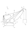
以下、図面を参照して、本発明の実施形態について説明する。図1は、本発明の一実施形態に係るクレーンの側面図である。図1に示すクレーン1は、クローラクレーンであり、例えば、連続壁工法による掘削作業に適用される。クレーン1は、走行体2と、旋回装置3を介して走行体2上に旋回可能に搭載された旋回体4と、旋回体4の先端部に起伏可能に取り付けられたブーム5と、ブーム5の先端に設けられたシーブ10,11とを有し、シーブ10を経由した主巻ロープ12およびシーブ11を経由した補巻ロープ13によって、掘削装置の一例であるバケット16が吊り下げられている。
Hereinafter, embodiments of the present invention will be described with reference to the drawings. FIG. 1 is a side view of a crane according to an embodiment of the present invention. The crane 1 shown in FIG. 1 is a crawler crane, and is applied to, for example, excavation work by a continuous wall construction method. The crane 1 includes a traveling body 2, a
主巻ロープ12、補巻ロープ13は旋回体4に搭載された主巻ウインチ6、補巻ウインチ7にそれぞれ巻回され、各ウインチ6,7の駆動によって各ロープ12,13が巻き取りまたは繰り出されてバケット16が昇降される。詳しくは後述するが、バケット16を水平に昇降させるために、各ウインチ6,7の駆動を同調させる制御(同調制御)が行われる。なお、ブーム5の先端部にはペンダントロープ14が接続されており、旋回体4に搭載された起伏ウインチ8の駆動により起伏ロープ15が巻き取りまたは繰り出されると、ペンダントロープ14を介してブーム5が起伏される。
The
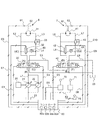
図2は、本実施形態に係るクレーンの油圧回路図である。図2に示すように、本実施形態における油圧回路は、原動機であるエンジン20と、油圧ポンプ21,22(油圧源)と、主巻ウインチ6を駆動するための油圧回路HC1と、補巻ウインチ7を駆動するための油圧回路HC2と、オペレータが主巻ウインチ6の巻上巻下指令を入力する主操作レバー70(第1の操作装置)と、補巻ウインチ7の巻上巻下指令を入力する補操作レバー71(第2の操作装置)と、を主に備えて構成される。なお、E1〜E10は電気配線を示す。
FIG. 2 is a hydraulic circuit diagram of the crane according to the present embodiment. As shown in FIG. 2, the hydraulic circuit in the present embodiment includes the
油圧ポンプ21および油圧ポンプ22は、例えば可変容量型のピストンポンプであり、エンジン20により駆動される。油圧回路HC1および油圧回路HC2は、油圧ポンプ21,22に対して直列に接続されており(シリーズ回路)、油圧ポンプ21,22から吐出された圧油は、油圧回路HC1、油圧回路HC2の順に流れてタンク23に戻る。
The
油圧回路HC1は、油圧アクチュエータである油圧モータ31(第1の油圧モータ)と、油圧ポンプ21,22から油圧モータ31へ供給される圧油の流れを制御する方向制御弁30(第1の方向制御弁)と、油圧モータ31と方向制御弁30とを接続する一対の管路L2,L3(第1の入口側管路、第1の出口側管路)と、カウンタバランス弁33と、管路L2および管路L3をつなぐバイパス管路L4(第1のバイパス管路)と、電磁切換弁32(第1の弁)と、を備えている。油圧モータ31は油圧ポンプ21,22から吐出される圧油により駆動される。油圧モータ31の出力軸の回転はウインチドラム50に伝達され、ウインチドラム50が巻上および巻下駆動される。なお、カウンタバランス弁33は、油圧モータ31の巻下げ方向の回転を制限するためのものである。
The hydraulic circuit HC1 includes a hydraulic motor 31 (first hydraulic motor), which is a hydraulic actuator, and a direction control valve 30 (first direction) that controls the flow of pressure oil supplied from the
同様に、油圧回路HC2は、油圧アクチュエータである油圧モータ41(第2の油圧モータ)と、油圧ポンプ21,22から油圧モータ41へ供給される圧油の流れを制御する方向制御弁40(第2の方向制御弁)と、油圧モータ41と方向制御弁40とを接続する一対の管路L6,L7(第2の入口側管路、第2の出口側管路)と、カウンタバランス弁43と、管路L6および管路L7をつなぐバイパス管路L8(第2のバイパス管路)と、電磁切換弁42(第2の弁)と、を備えている。油圧モータ41は油圧ポンプ21,22から吐出される圧油により駆動される。油圧モータ41の出力軸の回転はウインチドラム51に伝達され、ウインチドラム51が巻上および巻下駆動される。なお、カウンタバランス弁43は、油圧モータ41の巻下げ方向の回転を制限するためのものである。
Similarly, the hydraulic circuit HC2 is a hydraulic actuator 41 (second hydraulic motor) and a directional control valve 40 (second hydraulic motor) that controls the flow of pressure oil supplied from the
操作レバー70,71はいわゆる電気レバーであり、オペレータが操作レバー70,71を一方向または他方向に操作すると、操作レバー70,71の操作量に応じた制御信号が電気配線E1,E2を介してコントローラ60に出力される。勿論、操作レバー70,71は油圧式のレバーであっても良い。コントローラ60は、それら制御信号に応じた切換信号を、電気配線E3〜E6を介して方向制御弁30,40のパイロットポートに出力する。操作レバー70,71が中立位置にあるとき(非操作時)、方向制御弁30,40は、それぞれ位置B、位置Eの状態にある。操作レバー70,71を一方向に操作して巻上指令がコントローラ60に入力されると、方向制御弁30,40は、それぞれ位置A、位置Dに状態が切り換わる。一方、操作レバー70,71を他方向に操作して巻下指令がコントローラ60に入力されると、方向制御弁30,40は、それぞれ位置C、位置Fに状態が切り換わる。
The
方向制御弁30が位置Aに切り換えられると、油圧ポンプ21,22から吐出された圧油は、管路L1→管路L3→油圧モータ31→管路L2の順に流れて、油圧モータ31が主巻ロープ12を巻き上げる方向に回転駆動する。一方、方向制御弁30が位置Cに切り換えられると、油圧ポンプ21,22から吐出された圧油は、管路L1→管路L2→油圧モータ31→管路L3の順に流れて、油圧モータ31が主巻ロープ12を巻き下げる方向に回転駆動する。
When the
よって、油圧モータ31の巻下駆動時には、管路L2が油圧モータ31の入口側管路であり、管路L3が油圧モータ31の出口側管路となる。一方、油圧モータ31の巻上駆動時には、管路L3が油圧モータ31の入口側管路となり、管路L2が油圧モータ31の出口側管路となる。
Therefore, when the
また、方向制御弁40が位置Dに切り換えられると、油圧ポンプ21,22から吐出された圧油は、管路L1→油圧回路HC1→管路L5→方向制御弁40→管路L7→油圧モータ41→管路L6→方向制御弁40→管路L9→タンク23の順に流れて、油圧モータ41が補巻ロープ13を巻き上げる方向に回転駆動する。一方、方向制御弁40が位置Fに切り換えられると、油圧ポンプ21,22から吐出された圧油は、管路L1→油圧回路HC1→管路L5→方向制御弁40→管路L6→油圧モータ41→管路L7→方向制御弁40→管路L9→タンク23の順に流れて、油圧モータ31が補巻ロープ13を巻き下げる方向に回転駆動する。
Further, when the
よって、油圧モータ41の巻下駆動時には、管路L6が油圧モータ41の入口側管路であり、管路L7が油圧モータ31の出口側管路となる。一方、油圧モータ41の巻上駆動時には、管路L7が油圧モータ41の入口側管路となり、管路L6が油圧モータ41の出口側管路となる。
Therefore, when the
電磁切換弁32,42は、通常はコントローラ60から電気配線E7,E8を介して出力される閉指令により閉じており、コントローラ60から開指令が出力されると電磁切換弁32、42が励磁されて開き、油圧モータ31,41に供給される圧油の一部がバイパス管路L4,L8を流れる。これにより、油圧モータ31,41に供給される圧油の流量が減少する。その結果、油圧モータ31,41の回転数(回転量)が低下する。
The
電磁切換弁32の最大流量は、例えば30リットル/分である。一方、方向制御弁30の最大流量は、例えば500リットル/分である。即ち、電磁切換弁32の最大流量は、方向制御弁30の最大流量の10%以下となっている。これは、油圧モータ31を流れる圧油の全量をバイパス管路L4から流す必要はなく、油圧モータ31と油圧モータ41とを同調させるために必要な圧油の流量だけバイパス管路L4を介して流せれば足りるからである。なお、方向制御弁40と電磁切換弁42との関係についても同様である。
The maximum flow rate of the
ウインチドラム50,51には、それぞれドラム回転量を検出するための回転量検出器61,62(第1の回転検出手段、第2の回転検出手段)が設けられている。回転量検出器61,62は、例えばパルスエンコーダであり、ドラム1回転当たり所定数のパルスを出力する。回転量検出器61,62からの各検出信号(パルス)は電気配線E9,E10を介してコントローラ60に入力される。コントローラ60は、パルス数をカウントすることにより、ウインチドラム50,51の総回転量を検出することができる。
The winch drums 50 and 51 are provided with
ここで、ウインチドラム50,51はそれぞれ油圧モータ31,41に接続されているため、ウインチドラム50,51の回転量を検出することは油圧モータ31,41の回転量を検出することと同じである。そこで、本実施形態では、油圧モータ31,41の回転量をウインチドラム50,51の回転量により測定している。勿論、油圧モータ31,41の回転量を直接検出しても良い。
Here, since the winch drums 50 and 51 are connected to the
コントローラ60は、各種演算等を行うCPU60a、CPU60aによる演算を実行するためのプログラムを格納するROMやHDD等の記憶装置60b、CPU60aがプログラムを実行する際の作業領域となるRAM60c、および他の機器とデータを送受信する際のインタフェースである通信インタフェース(通信I/F)60dを含むハードウェアと、記憶装置60bに記憶され、CPU60aにより実行されるソフトウェアとから構成される。コントローラ60の各機能は、CPU60aが、記憶装置60bに格納された各種プログラムをRAM60cにロードして実行することにより、実現される。
The
次に、コントローラ60によるウインチ6,7の同調制御の詳細について、図3を用いて説明する。図3は、コントローラ60が実行するウインチ6,7の同調制御の手順を示すフローチャートである。コントローラ60は、操作レバー70,71の操作が「所定条件」を満たすか否かを監視する。具体的には、操作レバー70,71が同一方向(巻上方向または巻下方向)に最大量操作(フルレバー操作)された場合に、コントローラ60は「所定条件」を満たすと判定し(S1/Yes)、ウインチ6,7の同調制御を開始する。一方、所定条件を満たさない場合(S1/No)にはステップS1に戻る。
Next, the details of the tuning control of the
次いで、コントローラ60は、回転量検出器61により検出されたパルス数N1(総回転量)と回転量検出器62により検出されたパルス数N2(総回転量)との差ΔNをリアルタイムで演算し(S2)、差ΔNが第1の閾値T1(例えば、T1=2)以上になると(S3/Yes)、パルス数が多い方の油圧モータを駆動する油圧回路の電磁切換弁に開指令を出力する(S4)。
Next, the
例えば、油圧モータ31の回転量が油圧モータ41の回転量より大きい場合、油圧モータ31に対応する電磁切換弁32を開ける。すると、圧油の一部がバイパス管路L4を介して流れることで、油圧モータ31に供給される圧油の流量が少なくなるため、油圧モータ31の回転数が低下し、油圧モータ31と油圧モータ41とが同調して駆動する。油圧モータ41の回転量が大きい場合には、同様に電磁切換弁42を開けることで、油圧モータ41の回転数が低下し、油圧モータ31と油圧モータ41とが同調して駆動する。
For example, when the rotation amount of the
次に、コントローラ60は、パルス数の差ΔNが第2の閾値T2(例えば、T2=0)以下になったか否かを判定し(S5)、差ΔNが第2の閾値T2以下になった場合(S5/Yes)には、ステップS4で開けた電磁切換弁に閉指令を出力し、その電磁切換弁を閉じる(S6)。例えば、ステップS4で電磁切換弁32を開けて、油圧モータ31の回転数が低下し、油圧モータ31と油圧モータ41とが同調(主巻ウインチ6と補巻ウインチ7とが同調)すると、パルス差ΔNが0となる。そうすると、ステップS5でYesとなるため、コントローラ60はステップS6に進んで、電磁切換弁32を閉じる。そして、コントローラ60は、リターンとなってステップS1に戻る。なお、ステップS3でNoの場合、ステップS5でNoの場合にはステップS2に戻る。
Next, the
以上説明したように、本実施形態によれば、以下のような作用効果を奏することができる。 As described above, according to the present embodiment, the following effects can be obtained.
(1)バイパス管路L4に電磁切換弁32、バイパス管路L8に電磁切換弁42をそれぞれ設け、ウインチドラム50,51のパルス数の差ΔNに基づいて、電磁切換弁32,42の少なくとも一方を開けるように制御することにより、主巻ウインチ6と補巻ウインチ7とを高精度で同調させることができる。しかも、バイパス管路L4,L8と電磁切換弁32,42を設けるだけで良いので、油圧回路構成を簡素化できる。
(1) An
(2)電磁切換弁32,42は方向制御弁30,40より最大流量が小さく、例えば方向制御弁30,40の約10%程度であるため、方向制御弁30,40と比べて非常に小型な部品で済み、安価で、配置スペースも小さくて済む。また、最大流量が小さいため、電磁切換弁32,42を開閉した際においてもバイパス管路L4,L8を流れる圧油の流量を調整し易く、主巻ウインチ6と補巻ウインチ7との同調制御が安定する。
(2) The maximum flow rate of the
(3)油圧ポンプ21,22に対して、油圧回路HC1および油圧回路HC2を直列に接続した油圧回路構成としたので、各油圧回路に油圧ポンプを設ける必要がなく、油圧ポンプを小型化できる。しかも、上流側である油圧回路HC1の電磁切換弁32を開けた場合でも、下流側の油圧回路HC2には油圧ポンプ21,22から吐出された圧油の全量が流れるため、主巻ウインチ6と補巻ウインチ7との同調制御の精度は低下しない。
(3) Since the hydraulic circuit HC1 and the hydraulic circuit HC2 are connected in series to the
ここで、油圧モータ31,41のモータ傾転を調整して主巻ウインチ6と補巻ウインチ7との同調制御を行おうとすると、油圧ポンプ21,22のポンプ負荷圧(保持圧)が変化するので、油圧ポンプ21,22のポンプ傾転の調整が必要となり、同調制御が複雑で難しい。また、油圧回路HC1と油圧回路HC2とが直列に接続されていると、ポンプ傾転を調整して同調制御を行うのは非常に困難であり、別途、油圧ポンプ21,22から油圧回路HC1をバイパスして油圧回路HC2に接続するバイパスライン等を設けて、同調制御を行う必要が生じる。そのため、油圧回路が複雑で大型化する。これに対して、本実施形態では、電磁切換弁32,42の開閉動作を制御するだけで同調制御が可能となるので、同調制御が簡単であるという利点がある。
Here, when the motor tilts of the
(4)油圧モータ31と油圧モータ41との総回転量の差(ΔN)が第1の閾値T1および第2の閾値T2の範囲になるように電磁切換弁32,42を開閉するだけの制御で済むため、主巻ウインチ6と補巻ウインチ7との同調制御が簡単である。
(4) Control that only opens and closes the
なお、本発明は前述した実施形態に限定されず、本発明の要旨を逸脱しない範囲で種々の変形が可能であり、特許請求の範囲に記載された技術思想に含まれる技術的事項の全てが本発明の対象となる。前記実施形態は、好適な例を示したものであるが、当業者ならば、本明細書に開示の内容から、各種の代替例、修正例、変形例あるいは改良例を実現することができ、これらは添付の特許請求の範囲に記載された技術的範囲に含まれる。以下、その他の実施形態について言及する。 The present invention is not limited to the above-described embodiment, and various modifications can be made without departing from the gist of the present invention, and all the technical matters included in the technical idea described in the claims are all. It is the subject of the present invention. Although the above-described embodiment shows a suitable example, those skilled in the art can realize various alternative examples, modified examples, modified examples, or improved examples from the contents disclosed in the present specification. These are included in the technical scope described in the appended claims. Hereinafter, other embodiments will be referred to.
(その他の実施形態への言及)
図4は、その他の実施形態に係るクレーンの油圧回路図である。図4に示すように、バイパス管路L4,L8に、それぞれスローリターンチェック弁(一方向絞り弁)80,81を設ける構成としても良い。スローリターンチェック弁80,81は、一方向の流れは自由流れを許容し、逆方向の流れは絞りで流量規制する。例えば油圧回路HC1において、巻上時は管路L2と管路L3との圧力差が大きいが、巻下時は管路L2と管路L3との圧力差が小さくなる。そこで、バイパス管路L4にスローリターンチェック弁80を設け、巻上時には自由にバイパス管路L4に圧油を流し、巻下時にはバイパス管路L4を流れる圧油を制限することで、より高精度な主巻ウインチ6と補巻ウインチ7との同調制御を実現できる。油圧回路HC2にスローリターンチェック弁81を設けた理由も同様である。
(Reference to other embodiments)
FIG. 4 is a hydraulic circuit diagram of a crane according to another embodiment. As shown in FIG. 4, slow return check valves (one-way throttle valves) 80 and 81 may be provided in the bypass pipelines L4 and L8, respectively. The slow
また、図4に示すように、主巻ウインチ6と補巻ウインチ7との同調制御を開始するための開始ボタン75を設けておき、コントローラ60に開始ボタン75からの操作信号が入力されると、コントローラ60は所定条件が成立したと判断して、同調制御を開始するようにしても良い。即ち、開始ボタン75の操作の有無をステップS1(図3参照)の処理の代替例とすることができる。このようにすると、オペレータの好みに応じたクレーン1の運転ができるため、使い勝手が向上する。また、例えばクレーン1の運転を管理する管理サーバ等の外部から同調制御指令がコントローラ60に入力されると、コントローラ60は所定条件が成立したと判断して、同調制御を行うようにしても良い。
Further, as shown in FIG. 4, a
また、ウインチドラム50,51の回転量を検出する代わりに、例えば、シーブ10,11の回転量を検出しても良いし、主巻ロープ12および補巻ロープ13の移動量を検出して、その移動量の差に基づいて主巻ウインチ6と補巻ウインチ7との同調制御を行うようにしても良い。また、回転量の代わりに回転数を検出して同調制御しても良い。即ち、本発明における「油圧モータの回転数または回転量を検出する」とは、油圧モータ31,41の回転数または回転量を直接的にセンサで検出することに限定されず、油圧モータ31,41と連結されたウインチドラム50,51の回転数または回転量を検出することで油圧モータ31,41の回転数または回転量を間接的に検出することを含み、さらに、ブーム5の先端に設けられたシーブ10,11の回転数または回転量、あるいはロープ12,13の移動量もしくはロープ高さを検出することで間接的に油圧モータ31,41の回転数または回転量を検出することも含む。
Further, instead of detecting the rotation amount of the winch drums 50 and 51, for example, the rotation amount of the
また、コントローラ60にウインチドラム50,51に巻回されたロープ12,13の巻層、巻列の情報を入力し、これらの情報に基づいて、油圧モータ31,41の回転数または回転量を補正し、主巻ウインチ6と補巻ウインチ7との同調制御を行っても良い。
Further, information on the winding layers and winding rows of the
つまり、本発明における「同調制御」は、主巻ウインチ6と補巻ウインチ7の回転量(回転数)が同じになるように制御される構成に限定されず、例えば、油圧モータ31,41の回転数または回転量に対してロープ12,13の移動量が異なる場合には、ロープ12,13の移動量が同じになるように制御することが本発明の「同調制御」に該当する。
That is, the "tuning control" in the present invention is not limited to the configuration in which the rotation speed (rotation speed) of the main winding
また、バイパス管路L4,L8を流れる圧油の流量をきめ細かく制御したい場合には、電磁切換弁32の代わりに電磁比例弁を用いれば良い。また、パルス数の差ΔNの値によっては、コントローラ60からの指令により電磁切換弁32と電磁切換弁42の両方を開けることもできる。
Further, when it is desired to finely control the flow rate of the pressure oil flowing through the bypass pipes L4 and L8, an electromagnetic proportional valve may be used instead of the
また、主巻ウインチ6と補巻ウインチ7との同調制御を行うために、電磁切換弁32と電磁切換弁42のうち少なくとも一方を閉じるように制御しても良い。例えば、図2において電磁切換弁32,42は、非励磁の状態で開位置に保持されているが、非励磁の状態で閉位置に保持される構成を採用した場合、同調制御を行うために、電磁切換弁32,42の少なくとも一方を閉じる制御となる。
Further, in order to control the synchronization between the main winding
なお、クレーンの一例として、クローラクレーンを例示したが、本発明は、これに限らず、ホイールクレーン、トラッククレーン、ラフテレーンクレーン、オールテレーンクレーン等の他の移動式クレーンに加えて、タワークレーン、天井クレーン、ジブクレーン、引込みクレーン、スタッカークレーン、門型クレーン、アンローダ等のあらゆるクレーンに適用可能である。 Although a crawler crane has been illustrated as an example of a crane, the present invention is not limited to this, and in addition to other mobile cranes such as a wheel crane, a truck crane, a rough terrain crane, and an all terrain crane, a tower crane and a ceiling crane are used. It can be applied to all kinds of cranes such as cranes, jib cranes, retractable cranes, stacker cranes, portal cranes and unloaders.
1 クレーン
2 走行体
3 旋回装置
4 旋回体
5 ブーム
6 主巻ウインチ
7 補巻ウインチ
10,11 シーブ
12 主巻ロープ
13 補巻ロープ
16 バケット
20 エンジン
21,22 油圧ポンプ(油圧源)
23 タンク
30 方向制御弁(第1の方向制御弁)
31 油圧モータ(第1の油圧モータ)
32 電磁切換弁(第1の弁)
40 方向制御弁(第2の方向制御弁)
41 油圧モータ(第2の油圧モータ)
42 電磁切換弁(第2の弁)
50,51 ウインチドラム
60 コントローラ
70 主操作レバー(第1の操作装置)
71 補操作レバー(第2の操作装置)
75 開始ボタン
80,81 スローリターンチェック弁
L2,L3 管路(第1の入口側管路、第1の出口側管路)
L4 バイパス管路(第1のバイパス管路)
L6,L7 管路(第2の入口側管路、第2の出口側管路)
L8 バイパス管路(第2のバイパス管路)
1 Crane 2
23
31 Hydraulic motor (first hydraulic motor)
32 Electromagnetic switching valve (first valve)
40 directional control valve (second directional control valve)
41 Hydraulic motor (second hydraulic motor)
42 Electromagnetic switching valve (second valve)
50, 51
71 Supplementary operating lever (second operating device)
75
L4 bypass line (first bypass line)
L6, L7 pipelines (second inlet side pipeline, second outlet side pipeline)
L8 bypass line (second bypass line)
Claims (7)
前記油圧源からの圧油により駆動される第1の油圧モータと、
前記油圧源から供給される圧油が前記第1の油圧モータに向かって流れる第1の入口側管路と、
前記第1の油圧モータから排出された圧油が流れる第1の出口側管路と、
前記第1の入口側管路と前記第1の出口側管路とをつなぐ第1のバイパス管路と、
前記第1のバイパス管路に設けられた第1の弁と、
前記第1の油圧モータの回転数または回転量を直接的にまたは間接的に検出する第1の回転検出手段と、
前記油圧源からの圧油により駆動される第2の油圧モータと、
前記油圧源から供給される圧油が前記第2の油圧モータに向かって流れる第2の入口側管路と、
前記第2の油圧モータから排出された圧油が流れる第2の出口側管路と、
前記第2の入口側管路と前記第2の出口側管路とをつなぐ第2のバイパス管路と、
前記第2のバイパス管路に設けられた第2の弁と、
前記第2の油圧モータの回転数または回転量を直接的にまたは間接的に検出する第2の回転検出手段と、を備え、
前記第1の回転検出手段および前記第2の回転検出手段の検出結果に基づいて、前記第1の油圧モータと前記第2の油圧モータとを同調させるように、前記第1の弁および前記第2の弁のうち少なくとも一方の動作を制御する
ことを特徴とするクレーン。 With a hydraulic source,
A first hydraulic motor driven by pressure oil from the hydraulic source, and
A first inlet side pipeline through which the pressure oil supplied from the hydraulic source flows toward the first hydraulic motor, and
The first outlet side pipeline through which the pressure oil discharged from the first hydraulic motor flows, and
A first bypass line connecting the first inlet side line and the first exit side line, and a first bypass line.
The first valve provided in the first bypass line and
A first rotation detecting means for directly or indirectly detecting the rotation speed or the amount of rotation of the first hydraulic motor,
A second hydraulic motor driven by pressure oil from the hydraulic source, and
A second inlet side pipeline through which the pressure oil supplied from the hydraulic source flows toward the second hydraulic motor, and
The second outlet side pipeline through which the pressure oil discharged from the second hydraulic motor flows, and
A second bypass line connecting the second inlet side line and the second exit side line, and a second bypass line.
A second valve provided in the second bypass line and
A second rotation detecting means for directly or indirectly detecting the rotation speed or the amount of rotation of the second hydraulic motor is provided.
Based on the detection results of the first rotation detecting means and the second rotation detecting means, the first valve and the first valve so as to synchronize the first hydraulic motor with the second hydraulic motor. A crane characterized in controlling the operation of at least one of the two valves.
前記油圧源と前記第1の油圧モータとの間に設けられ、前記油圧源から供給される圧油の流れ方向を制御する第1の方向制御弁と、
前記第1の方向制御弁を操作する第1の操作装置と、
前記油圧源と前記第2の油圧モータとの間に設けられ、前記油圧源から供給される圧油の流れ方向を制御する第2の方向制御弁と、
前記第2の方向制御弁を操作する第2の操作装置と、をさらに備え、
前記第1の操作装置および前記第2の操作装置からの操作信号が所定条件を満たすことに基づいて、前記第1の油圧モータと前記第2の油圧モータとを同調させる制御を開始することを特徴とするクレーン。 In the crane according to claim 1,
A first directional control valve provided between the hydraulic source and the first hydraulic motor and controlling the flow direction of the pressure oil supplied from the hydraulic source.
A first operating device that operates the first directional control valve,
A second directional control valve provided between the hydraulic source and the second hydraulic motor and controlling the flow direction of the pressure oil supplied from the hydraulic source.
A second operating device for operating the second directional control valve is further provided.
Based on the operation signals from the first operating device and the second operating device satisfying a predetermined condition, the control for synchronizing the first hydraulic motor and the second hydraulic motor is started. Characterized crane.
前記所定条件は、前記第1の操作装置および前記第2の操作装置が何れも同一方向に最大の操作量で操作されていることであることを特徴とするクレーン。 In the crane according to claim 2.
The predetermined condition is that the first operating device and the second operating device are both operated in the same direction with the maximum amount of operation.
前記第1の弁は、前記第1の方向制御弁より最大流量が小さく、
前記第2の弁は、前記第2の方向制御弁より最大流量が小さい
ことを特徴とするクレーン。 In the crane according to claim 2 or 3.
The first valve has a smaller maximum flow rate than the first directional control valve.
The second valve is a crane characterized in that the maximum flow rate is smaller than that of the second directional control valve.
前記油圧源に対して、前記第1の油圧モータおよび前記第2の油圧モータが直列で接続されている
ことを特徴とするクレーン。 In the crane according to any one of claims 1 to 4.
A crane characterized in that the first hydraulic motor and the second hydraulic motor are connected in series to the hydraulic source.
前記第1のバイパス管路および前記第2のバイパス管路に、それぞれスローリターンチェック弁が設けられている
ことを特徴とするクレーン。 In the crane according to any one of claims 1 to 5,
A crane characterized in that slow return check valves are provided in the first bypass line and the second bypass line, respectively.
前記第1の油圧モータと前記第2の油圧モータとを同調させる制御の開始からのそれぞれの総回転数または総回転量の差が第1の閾値以上になると、前記第1の弁および前記第2の弁のうち、前記総回転数または前記総回転量の大きい油圧モータに対応する弁を開け、前記差が前記第1の閾値よりも小さい第2の閾値以下になると、開けられた前記弁を閉める
ことを特徴とするクレーン。
In the crane according to any one of claims 1 to 6.
When the difference between the total number of rotations or the total amount of rotations from the start of the control for synchronizing the first hydraulic motor and the second hydraulic motor becomes equal to or more than the first threshold value, the first valve and the first valve and the first. Of the two valves, the valve corresponding to the total rotation speed or the total rotation amount is opened, and when the difference becomes equal to or less than the second threshold value smaller than the first threshold value, the opened valve is opened. A crane characterized by closing.
Priority Applications (1)
| Application Number | Priority Date | Filing Date | Title |
|---|---|---|---|
| JP2020055482A JP7443120B2 (en) | 2020-03-26 | 2020-03-26 | crane |
Applications Claiming Priority (1)
| Application Number | Priority Date | Filing Date | Title |
|---|---|---|---|
| JP2020055482A JP7443120B2 (en) | 2020-03-26 | 2020-03-26 | crane |
Publications (2)
| Publication Number | Publication Date |
|---|---|
| JP2021155152A true JP2021155152A (en) | 2021-10-07 |
| JP7443120B2 JP7443120B2 (en) | 2024-03-05 |
Family
ID=77916655
Family Applications (1)
| Application Number | Title | Priority Date | Filing Date |
|---|---|---|---|
| JP2020055482A Active JP7443120B2 (en) | 2020-03-26 | 2020-03-26 | crane |
Country Status (1)
| Country | Link |
|---|---|
| JP (1) | JP7443120B2 (en) |
Citations (3)
| Publication number | Priority date | Publication date | Assignee | Title |
|---|---|---|---|---|
| US4305571A (en) * | 1977-02-01 | 1981-12-15 | Karmoy Mekaniske Verksted A/S | Means for regulating two trawl winches |
| JPS60162584U (en) * | 1984-04-06 | 1985-10-29 | 石川島播磨重工業株式会社 | Double deck crane synchronization adjustment device |
| JP2017024834A (en) * | 2015-07-17 | 2017-02-02 | コベルコ建機株式会社 | Control device of winch |
-
2020
- 2020-03-26 JP JP2020055482A patent/JP7443120B2/en active Active
Patent Citations (3)
| Publication number | Priority date | Publication date | Assignee | Title |
|---|---|---|---|---|
| US4305571A (en) * | 1977-02-01 | 1981-12-15 | Karmoy Mekaniske Verksted A/S | Means for regulating two trawl winches |
| JPS60162584U (en) * | 1984-04-06 | 1985-10-29 | 石川島播磨重工業株式会社 | Double deck crane synchronization adjustment device |
| JP2017024834A (en) * | 2015-07-17 | 2017-02-02 | コベルコ建機株式会社 | Control device of winch |
Also Published As
| Publication number | Publication date |
|---|---|
| JP7443120B2 (en) | 2024-03-05 |
Similar Documents
| Publication | Publication Date | Title |
|---|---|---|
| JP7261894B2 (en) | electric hydraulic working machine | |
| KR20010034403A (en) | Revolution control device | |
| JP5669264B2 (en) | Hydraulic control device for work | |
| US20190194908A1 (en) | Construction Machine | |
| JP7433100B2 (en) | Hydraulic drive system for working machines | |
| EP3730446B1 (en) | Crane | |
| JPH0741287A (en) | Boom derricking and hoisting motion control device of crane | |
| JP2744117B2 (en) | Turning control device for cranes, etc. | |
| JP7443120B2 (en) | crane | |
| JP2001199676A (en) | Hydraulic circuit for operation system of construction machine | |
| JP3078947B2 (en) | Drive control device for fluid pressure actuator | |
| JP2005263470A (en) | Winch speed control device, and winch speed control method | |
| JPH11139774A (en) | Random winding preventing device of winch | |
| JP7766501B2 (en) | crane | |
| JP2024136810A (en) | CONTROL DEVICE FOR WORKING MACHINE, CONTROL DEVICE, AND CONTROL METHOD FOR WORKING MACHINE | |
| JP2019002558A (en) | Rotary driving device, and work machine with the same | |
| JP2025122247A (en) | crane | |
| JP3507101B2 (en) | Drive circuit for hydraulic motor | |
| JP5156469B2 (en) | Winch equipment | |
| JP7766502B2 (en) | crane | |
| JP2018184299A (en) | Revolving drive device and work machine with the same | |
| JP3658327B2 (en) | Winch control equipment | |
| JP6479572B2 (en) | Swivel control device and work machine | |
| JP4161450B2 (en) | Luggage suspension device | |
| JP2002012392A (en) | Winch control device |
Legal Events
| Date | Code | Title | Description |
|---|---|---|---|
| A625 | Written request for application examination (by other person) |
Free format text: JAPANESE INTERMEDIATE CODE: A625 Effective date: 20230118 |
|
| A977 | Report on retrieval |
Free format text: JAPANESE INTERMEDIATE CODE: A971007 Effective date: 20231110 |
|
| A131 | Notification of reasons for refusal |
Free format text: JAPANESE INTERMEDIATE CODE: A131 Effective date: 20231114 |
|
| A521 | Request for written amendment filed |
Free format text: JAPANESE INTERMEDIATE CODE: A523 Effective date: 20240115 |
|
| TRDD | Decision of grant or rejection written | ||
| A01 | Written decision to grant a patent or to grant a registration (utility model) |
Free format text: JAPANESE INTERMEDIATE CODE: A01 Effective date: 20240123 |
|
| A61 | First payment of annual fees (during grant procedure) |
Free format text: JAPANESE INTERMEDIATE CODE: A61 Effective date: 20240221 |
|
| R150 | Certificate of patent or registration of utility model |
Ref document number: 7443120 Country of ref document: JP Free format text: JAPANESE INTERMEDIATE CODE: R150 |