JP2020184870A - 高周波ジェネレータおよびその動作方法 - Google Patents
高周波ジェネレータおよびその動作方法 Download PDFInfo
- Publication number
- JP2020184870A JP2020184870A JP2019110832A JP2019110832A JP2020184870A JP 2020184870 A JP2020184870 A JP 2020184870A JP 2019110832 A JP2019110832 A JP 2019110832A JP 2019110832 A JP2019110832 A JP 2019110832A JP 2020184870 A JP2020184870 A JP 2020184870A
- Authority
- JP
- Japan
- Prior art keywords
- frequency
- ignition
- voltage
- load
- signal
- Prior art date
- Legal status (The legal status is an assumption and is not a legal conclusion. Google has not performed a legal analysis and makes no representation as to the accuracy of the status listed.)
- Granted
Links
Images
Classifications
-
- H—ELECTRICITY
- H01—ELECTRIC ELEMENTS
- H01J—ELECTRIC DISCHARGE TUBES OR DISCHARGE LAMPS
- H01J37/00—Discharge tubes with provision for introducing objects or material to be exposed to the discharge, e.g. for the purpose of examination or processing thereof
- H01J37/32—Gas-filled discharge tubes
- H01J37/32009—Arrangements for generation of plasma specially adapted for examination or treatment of objects, e.g. plasma sources
- H01J37/32082—Radio frequency generated discharge
- H01J37/32137—Radio frequency generated discharge controlling of the discharge by modulation of energy
- H01J37/32146—Amplitude modulation, includes pulsing
-
- H—ELECTRICITY
- H02—GENERATION; CONVERSION OR DISTRIBUTION OF ELECTRIC POWER
- H02M—APPARATUS FOR CONVERSION BETWEEN AC AND AC, BETWEEN AC AND DC, OR BETWEEN DC AND DC, AND FOR USE WITH MAINS OR SIMILAR POWER SUPPLY SYSTEMS; CONVERSION OF DC OR AC INPUT POWER INTO SURGE OUTPUT POWER; CONTROL OR REGULATION THEREOF
- H02M3/00—Conversion of DC power input into DC power output
- H02M3/22—Conversion of DC power input into DC power output with intermediate conversion into AC
- H02M3/24—Conversion of DC power input into DC power output with intermediate conversion into AC by static converters
- H02M3/28—Conversion of DC power input into DC power output with intermediate conversion into AC by static converters using discharge tubes with control electrode or semiconductor devices with control electrode to produce the intermediate AC
- H02M3/325—Conversion of DC power input into DC power output with intermediate conversion into AC by static converters using discharge tubes with control electrode or semiconductor devices with control electrode to produce the intermediate AC using devices of a triode or a transistor type requiring continuous application of a control signal
- H02M3/335—Conversion of DC power input into DC power output with intermediate conversion into AC by static converters using discharge tubes with control electrode or semiconductor devices with control electrode to produce the intermediate AC using devices of a triode or a transistor type requiring continuous application of a control signal using semiconductor devices only
-
- H—ELECTRICITY
- H01—ELECTRIC ELEMENTS
- H01J—ELECTRIC DISCHARGE TUBES OR DISCHARGE LAMPS
- H01J37/00—Discharge tubes with provision for introducing objects or material to be exposed to the discharge, e.g. for the purpose of examination or processing thereof
- H01J37/32—Gas-filled discharge tubes
- H01J37/32009—Arrangements for generation of plasma specially adapted for examination or treatment of objects, e.g. plasma sources
- H01J37/32082—Radio frequency generated discharge
- H01J37/32174—Circuits specially adapted for controlling the RF discharge
-
- H—ELECTRICITY
- H02—GENERATION; CONVERSION OR DISTRIBUTION OF ELECTRIC POWER
- H02M—APPARATUS FOR CONVERSION BETWEEN AC AND AC, BETWEEN AC AND DC, OR BETWEEN DC AND DC, AND FOR USE WITH MAINS OR SIMILAR POWER SUPPLY SYSTEMS; CONVERSION OF DC OR AC INPUT POWER INTO SURGE OUTPUT POWER; CONTROL OR REGULATION THEREOF
- H02M1/00—Details of apparatus for conversion
- H02M1/0064—Magnetic structures combining different functions, e.g. storage, filtering or transformation
-
- H—ELECTRICITY
- H02—GENERATION; CONVERSION OR DISTRIBUTION OF ELECTRIC POWER
- H02M—APPARATUS FOR CONVERSION BETWEEN AC AND AC, BETWEEN AC AND DC, OR BETWEEN DC AND DC, AND FOR USE WITH MAINS OR SIMILAR POWER SUPPLY SYSTEMS; CONVERSION OF DC OR AC INPUT POWER INTO SURGE OUTPUT POWER; CONTROL OR REGULATION THEREOF
- H02M1/00—Details of apparatus for conversion
- H02M1/08—Circuits specially adapted for the generation of control voltages for semiconductor devices incorporated in static converters
-
- H—ELECTRICITY
- H02—GENERATION; CONVERSION OR DISTRIBUTION OF ELECTRIC POWER
- H02M—APPARATUS FOR CONVERSION BETWEEN AC AND AC, BETWEEN AC AND DC, OR BETWEEN DC AND DC, AND FOR USE WITH MAINS OR SIMILAR POWER SUPPLY SYSTEMS; CONVERSION OF DC OR AC INPUT POWER INTO SURGE OUTPUT POWER; CONTROL OR REGULATION THEREOF
- H02M1/00—Details of apparatus for conversion
- H02M1/32—Means for protecting converters other than automatic disconnection
-
- H—ELECTRICITY
- H02—GENERATION; CONVERSION OR DISTRIBUTION OF ELECTRIC POWER
- H02M—APPARATUS FOR CONVERSION BETWEEN AC AND AC, BETWEEN AC AND DC, OR BETWEEN DC AND DC, AND FOR USE WITH MAINS OR SIMILAR POWER SUPPLY SYSTEMS; CONVERSION OF DC OR AC INPUT POWER INTO SURGE OUTPUT POWER; CONTROL OR REGULATION THEREOF
- H02M7/00—Conversion of AC power input into DC power output; Conversion of DC power input into AC power output
- H02M7/42—Conversion of DC power input into AC power output without possibility of reversal
- H02M7/44—Conversion of DC power input into AC power output without possibility of reversal by static converters
- H02M7/48—Conversion of DC power input into AC power output without possibility of reversal by static converters using discharge tubes with control electrode or semiconductor devices with control electrode
- H02M7/53—Conversion of DC power input into AC power output without possibility of reversal by static converters using discharge tubes with control electrode or semiconductor devices with control electrode using devices of a triode or transistor type requiring continuous application of a control signal
- H02M7/537—Conversion of DC power input into AC power output without possibility of reversal by static converters using discharge tubes with control electrode or semiconductor devices with control electrode using devices of a triode or transistor type requiring continuous application of a control signal using semiconductor devices only, e.g. single switched pulse inverters
- H02M7/539—Conversion of DC power input into AC power output without possibility of reversal by static converters using discharge tubes with control electrode or semiconductor devices with control electrode using devices of a triode or transistor type requiring continuous application of a control signal using semiconductor devices only, e.g. single switched pulse inverters with automatic control of output wave form or frequency
- H02M7/5395—Conversion of DC power input into AC power output without possibility of reversal by static converters using discharge tubes with control electrode or semiconductor devices with control electrode using devices of a triode or transistor type requiring continuous application of a control signal using semiconductor devices only, e.g. single switched pulse inverters with automatic control of output wave form or frequency by pulse-width modulation
-
- H—ELECTRICITY
- H02—GENERATION; CONVERSION OR DISTRIBUTION OF ELECTRIC POWER
- H02M—APPARATUS FOR CONVERSION BETWEEN AC AND AC, BETWEEN AC AND DC, OR BETWEEN DC AND DC, AND FOR USE WITH MAINS OR SIMILAR POWER SUPPLY SYSTEMS; CONVERSION OF DC OR AC INPUT POWER INTO SURGE OUTPUT POWER; CONTROL OR REGULATION THEREOF
- H02M1/00—Details of apparatus for conversion
- H02M1/0067—Converter structures employing plural converter units, other than for parallel operation of the units on a single load
- H02M1/007—Plural converter units in cascade
-
- H—ELECTRICITY
- H02—GENERATION; CONVERSION OR DISTRIBUTION OF ELECTRIC POWER
- H02M—APPARATUS FOR CONVERSION BETWEEN AC AND AC, BETWEEN AC AND DC, OR BETWEEN DC AND DC, AND FOR USE WITH MAINS OR SIMILAR POWER SUPPLY SYSTEMS; CONVERSION OF DC OR AC INPUT POWER INTO SURGE OUTPUT POWER; CONTROL OR REGULATION THEREOF
- H02M1/00—Details of apparatus for conversion
- H02M1/44—Circuits or arrangements for compensating for electromagnetic interference in converters or inverters
-
- H—ELECTRICITY
- H02—GENERATION; CONVERSION OR DISTRIBUTION OF ELECTRIC POWER
- H02M—APPARATUS FOR CONVERSION BETWEEN AC AND AC, BETWEEN AC AND DC, OR BETWEEN DC AND DC, AND FOR USE WITH MAINS OR SIMILAR POWER SUPPLY SYSTEMS; CONVERSION OF DC OR AC INPUT POWER INTO SURGE OUTPUT POWER; CONTROL OR REGULATION THEREOF
- H02M7/00—Conversion of AC power input into DC power output; Conversion of DC power input into AC power output
- H02M7/42—Conversion of DC power input into AC power output without possibility of reversal
- H02M7/44—Conversion of DC power input into AC power output without possibility of reversal by static converters
- H02M7/48—Conversion of DC power input into AC power output without possibility of reversal by static converters using discharge tubes with control electrode or semiconductor devices with control electrode
- H02M7/4815—Resonant converters
-
- Y—GENERAL TAGGING OF NEW TECHNOLOGICAL DEVELOPMENTS; GENERAL TAGGING OF CROSS-SECTIONAL TECHNOLOGIES SPANNING OVER SEVERAL SECTIONS OF THE IPC; TECHNICAL SUBJECTS COVERED BY FORMER USPC CROSS-REFERENCE ART COLLECTIONS [XRACs] AND DIGESTS
- Y02—TECHNOLOGIES OR APPLICATIONS FOR MITIGATION OR ADAPTATION AGAINST CLIMATE CHANGE
- Y02B—CLIMATE CHANGE MITIGATION TECHNOLOGIES RELATED TO BUILDINGS, e.g. HOUSING, HOUSE APPLIANCES OR RELATED END-USER APPLICATIONS
- Y02B70/00—Technologies for an efficient end-user side electric power management and consumption
- Y02B70/10—Technologies improving the efficiency by using switched-mode power supplies [SMPS], i.e. efficient power electronics conversion e.g. power factor correction or reduction of losses in power supplies or efficient standby modes
Landscapes
- Engineering & Computer Science (AREA)
- Power Engineering (AREA)
- Physics & Mathematics (AREA)
- Plasma & Fusion (AREA)
- Chemical & Material Sciences (AREA)
- Analytical Chemistry (AREA)
- Inverter Devices (AREA)
Abstract
Description

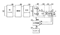
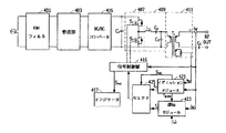
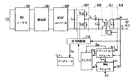
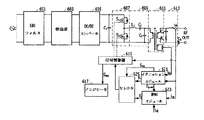
本発明のさらに他の実施形態に係る高周波ジェネレータは、EMIフィルタ501と、整流部503と、DC/DCコンバータ505と、インバータ507と、LCフィルタ509と、トランスフォーマ511と、リンギング除去部513と、信号制御部515と、インジケータ517と、イグニッションモジュール521と、運転モジュール523と、セレクタ525とを含む。
203、403、503、603:整流部
205、405、505、605:DC/DCコンバータ
207、407、507、607:インバータ
209、409、509、609:LCフィルタ
211、411、511、611:トランスフォーマ
213、413、513、613:リンギング除去部
215、415、515、615:信号制御部
217、417、517、617:インジケータ
421、521、621:イグニッションモジュール
423、523、623:運転モジュール
425、525、625:セレクタ
Claims (13)
- 商用電源の交流電圧を直流電圧に整流して出力する整流部と、
前記整流部から出力される直流電圧を第2直流電圧に変換するDC/DCコンバータと、
PWM制御信号で制御される交互に動作する第1および第2スイッチング素子を含み、前記DC/DCコンバータから出力される所定レベルの直流電圧を所定レベルの交流電圧に変換するインバータと、
前記インバータの出力端に直並列に結合されたインダクタおよびキャパシタを備え、前記インバータから出力される高周波信号から所定の共振周波数を有するサイン波形の共振信号を出力するLCフィルタと、
前記LCフィルタから出力されるパルス波形の高周波電力信号を2次側に誘導するトランスフォーマと、
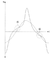
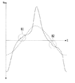
高周波負荷検出電流がイグニッション負荷設定電流より大きければ、イグニッションモードを終了し、イグニッションモード終了時のスイッチング周波数をイグニッションモード離脱周波数にセットし、モード選択信号を出力するイグニッションモジュールと、
前記イグニッションモジュールから出力されるイグニッションモード離脱周波数を運転モード時のスイッチング周波数の初期値に適用する運転モジュールと、
前記スイッチング周波数を用いて、前記PWM制御信号を生成する信号制御部とを含む高周波ジェネレータ。 - イグニッションモード時、前記イグニッションモジュールから出力されるスイッチング周波数を選択し、イグニッションモード終了時、前記モード選択信号で制御され、運転モード時、前記運転モジュールから出力されるスイッチング周波数を選択するセレクタをさらに含む、請求項1に記載の高周波ジェネレータ。
- 前記トランスフォーマの2次側に並列連結され、前記トランスフォーマの2次側に存在する漏れインダクタンス成分と高周波負荷に寄生する寄生キャパシタンス成分による共振現象によって高周波負荷電流波形に現れるリンギング現象を除去するリンギング除去部をさらに含む、請求項2に記載の高周波ジェネレータ。
- 前記リンギング除去部は、キャパシタからなる、請求項3に記載の高周波ジェネレータ。
- 前記リンギング除去部は、直列連結された抵抗およびキャパシタからなる、請求項2に記載の高周波ジェネレータ。
- 前記信号制御部は、高周波負荷検出電流が入力され、高周波負荷検出電流の状態を表示するように状態信号を出力し、
前記状態信号に応答して前記高周波負荷検出電流の状態を表示するインジケータをさらに含む、請求項4に記載の高周波ジェネレータ。 - 前記イグニッションモジュールは、
高周波負荷側で検出される高周波負荷検出電流とイグニッション負荷設定電流とを比較し、高周波負荷検出電流がイグニッション負荷設定電流より小さければ、高周波負荷側で検出される高周波負荷検出電圧とイグニッション負荷設定電圧とを比較し、高周波負荷検出電流がイグニッション負荷設定電流より大きいか等しければ、イグニッションモードを終了し、終了時のスイッチング周波数をイグニッションモード離脱周波数にセットし、高周波負荷検出電圧がイグニッション負荷設定電圧より小さければ、スイッチング周波数を所定周波数だけ減少させ、高周波負荷検出電圧がイグニッション負荷設定電圧より大きければ、スイッチング周波数を現在通りに維持し、
前記運転モジュールは、イグニッションモード離脱周波数を運転モードにおけるスイッチング周波数の初期値に適用する、請求項2に記載の高周波ジェネレータ。 - 商用電源の交流電圧を直流電圧に整流して出力する整流部と、
前記整流部から出力される直流電圧を第2直流電圧に変換するDC/DCコンバータと、
PWM制御信号で制御される交互に動作する第1および第2スイッチング素子を含み、前記DC/DCコンバータから出力される所定レベルの直流電圧を所定レベルの交流電圧に変換するインバータと、
前記インバータの出力端に直並列に結合されたインダクタおよびキャパシタを備え、前記インバータから出力される高周波信号から所定の共振周波数を有するサイン波形の共振信号を出力するLCフィルタと、
前記LCフィルタから出力されるパルス波形の高周波電力信号を2次側に誘導するトランスフォーマと、
高周波負荷側の高周波負荷検出電流と高周波負荷検出電圧とを用いて、前記PWM制御信号を生成する信号制御部とを含む高周波ジェネレータ。 - 前記トランスフォーマの2次側に並列連結され、前記トランスフォーマの2次側に存在する漏れインダクタンス成分と高周波負荷に寄生する寄生キャパシタンス成分による共振現象によって高周波負荷電流波形に現れるリンギング現象を除去するリンギング除去部をさらに含む、請求項8に記載の高周波ジェネレータ。
- 前記リンギング除去部は、キャパシタからなる、請求項9に記載の高周波ジェネレータ。
- 前記リンギング除去部は、直列連結された抵抗およびキャパシタからなる、請求項9に記載の高周波ジェネレータ。
- 前記信号制御部は、高周波負荷検出電流が入力され、高周波負荷検出電流の状態を表示するように状態信号を出力し、
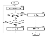
前記状態信号に応答して前記高周波負荷検出電流の状態を表示するインジケータをさらに含む、請求項9に記載の高周波ジェネレータ。 - イグニッションモードと運転モードとで動作する高周波ジェネレータの動作方法において、
前記高周波ジェネレータがイグニッションモードに入る第1ステップと、
イグニッションモジュールが、高周波負荷側で検出される高周波負荷検出電流とイグニッション負荷設定電流とを比較する第2ステップと、
高周波負荷検出電流がイグニッション負荷設定電流より小さければ、前記イグニッションモジュールが、高周波負荷側で検出される高周波負荷検出電圧とイグニッション負荷設定電圧とを比較する第3ステップと、
高周波負荷検出電流がイグニッション負荷設定電流より大きいか等しければ、前記イグニッションモジュールは、イグニッションモードを終了し、終了時のスイッチング周波数をイグニッションモード離脱周波数にセットする第4ステップと、
高周波負荷検出電圧がイグニッション負荷設定電圧より小さければ、前記イグニッションモジュールは、スイッチング周波数を所定周波数だけ減少させ、前記第2ステップに戻る第5ステップと、
高周波負荷検出電圧がイグニッション負荷設定電圧より大きければ、前記イグニッションモジュールは、スイッチング周波数を現在通りに維持したまま、前記第2ステップに戻る第6ステップと、
運転モジュールが、イグニッションモード離脱周波数を運転モードにおけるスイッチング周波数の初期値に適用し、高周波負荷検出電流と外部から入力される高周波負荷設定電流とを用いて、スイッチング周波数を生成する第7ステップとを含む高周波ジェネレータの動作方法。
Applications Claiming Priority (2)
| Application Number | Priority Date | Filing Date | Title |
|---|---|---|---|
| KR1020190053516A KR102242234B1 (ko) | 2019-05-08 | 2019-05-08 | 고주파 제너레이터 및 그의 동작 방법 |
| KR10-2019-0053516 | 2019-05-08 |
Publications (2)
| Publication Number | Publication Date |
|---|---|
| JP2020184870A true JP2020184870A (ja) | 2020-11-12 |
| JP6802577B2 JP6802577B2 (ja) | 2020-12-16 |
Family
ID=72944648
Family Applications (1)
| Application Number | Title | Priority Date | Filing Date |
|---|---|---|---|
| JP2019110832A Expired - Fee Related JP6802577B2 (ja) | 2019-05-08 | 2019-06-14 | 高周波ジェネレータおよびその動作方法 |
Country Status (4)
| Country | Link |
|---|---|
| US (2) | US10818474B1 (ja) |
| JP (1) | JP6802577B2 (ja) |
| KR (1) | KR102242234B1 (ja) |
| TW (1) | TWI714126B (ja) |
Families Citing this family (4)
| Publication number | Priority date | Publication date | Assignee | Title |
|---|---|---|---|---|
| US11146164B2 (en) * | 2020-01-21 | 2021-10-12 | The Florida State University Research Foundation, Inc. | Single transformer-based gate driver |
| WO2023081110A1 (en) * | 2021-11-03 | 2023-05-11 | Lam Research Corporation | Method and apparatus for automated regulation of a frequency-modulated multilevel outphasing power amplifier |
| CN115664177A (zh) * | 2022-10-20 | 2023-01-31 | 华为数字能源技术有限公司 | 一种不间断电源的配电电路和供电系统 |
| CN117545162B (zh) * | 2023-11-08 | 2024-05-28 | 江苏神州半导体科技有限公司 | 一种远程等离子源的预激发点火装置及其控制方法 |
Family Cites Families (17)
| Publication number | Priority date | Publication date | Assignee | Title |
|---|---|---|---|---|
| JP3603643B2 (ja) * | 1999-02-15 | 2004-12-22 | 松下電工株式会社 | 放電灯点灯装置 |
| TW428847U (en) * | 1999-06-05 | 2001-04-01 | Ind Tech Res Inst | Conversion circuit for ringing current choke with dual factor feedback control |
| TW501334B (en) * | 2001-01-20 | 2002-09-01 | Skynet Electronic Co Ltd | Ringing-free zero-voltage switching method for power converter |
| US6522089B1 (en) * | 2001-10-23 | 2003-02-18 | Orsam Sylvania Inc. | Electronic ballast and method for arc straightening |
| JP2006211877A (ja) | 2005-01-31 | 2006-08-10 | Tdk Corp | スイッチング電源装置 |
| JP4418424B2 (ja) | 2005-11-21 | 2010-02-17 | 日本リライアンス株式会社 | 交流電源装置およびその装置におけるアーク抑制方法 |
| KR101391874B1 (ko) * | 2008-01-10 | 2014-05-07 | (주) 이이시스 | 용량성 부하특성을 갖는 공진형 고전압 제어 장치 |
| US7721697B2 (en) * | 2008-01-31 | 2010-05-25 | West Virginia University | Plasma generating ignition system and associated method |
| CN102458027B (zh) * | 2010-10-22 | 2014-05-07 | 台达电子工业股份有限公司 | 点灯电路的控制方法及其所适用的点灯电路 |
| US8786371B2 (en) * | 2011-11-18 | 2014-07-22 | Skyworks Solutions, Inc. | Apparatus and methods for voltage converters |
| DE12884309T1 (de) * | 2012-09-05 | 2015-09-17 | Kyosan Electric Mfg. Co., Ltd. | Gleichstromversorgungsvorrichtung und steuerungsverfahren für die gleichstromversorgungsvorrichtung |
| IN2014KN03106A (ja) | 2012-09-07 | 2015-05-08 | Kyosan Electric Mfg | |
| JP6107132B2 (ja) | 2012-12-28 | 2017-04-05 | 富士電機株式会社 | スイッチング電源装置 |
| JP5729732B2 (ja) | 2013-09-27 | 2015-06-03 | 株式会社京三製作所 | 直流電源装置、直流電源装置の制御方法 |
| JP6413261B2 (ja) * | 2014-03-03 | 2018-10-31 | 株式会社島津製作所 | Icp発光分析装置用高周波電源装置 |
| JP6414676B2 (ja) * | 2014-09-10 | 2018-10-31 | パナソニックIpマネジメント株式会社 | 点灯装置及び照明器具 |
| JP5788616B1 (ja) * | 2015-02-04 | 2015-10-07 | 株式会社京三製作所 | 高周波電源装置、及びデュアルカソード用電源 |
-
2019
- 2019-05-08 KR KR1020190053516A patent/KR102242234B1/ko active Active
- 2019-05-24 US US16/421,734 patent/US10818474B1/en active Active
- 2019-06-14 TW TW108120675A patent/TWI714126B/zh not_active IP Right Cessation
- 2019-06-14 JP JP2019110832A patent/JP6802577B2/ja not_active Expired - Fee Related
-
2020
- 2020-01-10 US US16/739,553 patent/US20200357609A1/en not_active Abandoned
Also Published As
| Publication number | Publication date |
|---|---|
| TW202042599A (zh) | 2020-11-16 |
| US20200357608A1 (en) | 2020-11-12 |
| KR20200129307A (ko) | 2020-11-18 |
| KR102242234B1 (ko) | 2021-04-20 |
| US20200357609A1 (en) | 2020-11-12 |
| US10818474B1 (en) | 2020-10-27 |
| TWI714126B (zh) | 2020-12-21 |
| JP6802577B2 (ja) | 2020-12-16 |
Similar Documents
| Publication | Publication Date | Title |
|---|---|---|
| JP6802577B2 (ja) | 高周波ジェネレータおよびその動作方法 | |
| US9450519B2 (en) | DC power source, and DC power source control method | |
| WO2012033120A1 (ja) | 電源用集積回路装置および電源遮断検出方法 | |
| JP6758504B2 (ja) | 溶接電流源 | |
| JP3719352B2 (ja) | プラズマ発生用電源装置及びその製造方法 | |
| KR101844981B1 (ko) | 플라즈마 공정용 llcc 공진컨버터 | |
| CN109314460B (zh) | 电力转换装置 | |
| JP2021065052A (ja) | プラズマ装置用直流パルス電源装置 | |
| JP3868624B2 (ja) | プラズマ発生用電源装置 | |
| US11112446B2 (en) | Circuit arrangement for a high-voltage test installation | |
| KR102125026B1 (ko) | 플라즈마 전원용 공진 네트워크 및 플라즈마 발생기용 전력공급장치 | |
| JP3206521B2 (ja) | 高周波加熱装置 | |
| CN105604766A (zh) | 内燃机的电晕点火系统 | |
| WO2011010481A1 (ja) | 放電管点灯装置および該装置における異常放電検出方法 | |
| JP3118849U (ja) | 電流探査モードのアーク放電保護装置 | |
| RU2608179C2 (ru) | Цепь защиты устройства высокочастотного индукционного нагрева и устройство высокочастотного индукционного нагрева с цепью защиты | |
| US6075327A (en) | Power supply apparatus for a discharge lamp, especially for a motor vehicle headlight | |
| US20250044372A1 (en) | Circuit for conduction testing of power supply of plasma globe lamp | |
| US7327094B2 (en) | Circuit arrangement and method for operating at least one electric lamp | |
| TW201345157A (zh) | 電源供應器的零電流偵測器及方法 | |
| JP2005340185A (ja) | プラズマ発生用電源装置の製造方法 | |
| KR101524314B1 (ko) | 소음 저감 장치 | |
| KR101458933B1 (ko) | 멀티레벨 공진부하용 전력 변환 시스템 및 그 제어 방법 | |
| KR20120052379A (ko) | 적어도 하나의 방전 램프를 동작시키기 위한 전자식 안정기 | |
| JP2015095378A (ja) | 高電圧発生回路およびそれを用いたイオンポンプ |
Legal Events
| Date | Code | Title | Description |
|---|---|---|---|
| A621 | Written request for application examination |
Free format text: JAPANESE INTERMEDIATE CODE: A621 Effective date: 20190620 |
|
| A131 | Notification of reasons for refusal |
Free format text: JAPANESE INTERMEDIATE CODE: A131 Effective date: 20200818 |
|
| A521 | Request for written amendment filed |
Free format text: JAPANESE INTERMEDIATE CODE: A523 Effective date: 20200903 |
|
| TRDD | Decision of grant or rejection written | ||
| A01 | Written decision to grant a patent or to grant a registration (utility model) |
Free format text: JAPANESE INTERMEDIATE CODE: A01 Effective date: 20201110 |
|
| A61 | First payment of annual fees (during grant procedure) |
Free format text: JAPANESE INTERMEDIATE CODE: A61 Effective date: 20201119 |
|
| R150 | Certificate of patent or registration of utility model |
Ref document number: 6802577 Country of ref document: JP Free format text: JAPANESE INTERMEDIATE CODE: R150 |
|
| LAPS | Cancellation because of no payment of annual fees |