JP2020004539A - 端子金具 - Google Patents
端子金具 Download PDFInfo
- Publication number
- JP2020004539A JP2020004539A JP2018121087A JP2018121087A JP2020004539A JP 2020004539 A JP2020004539 A JP 2020004539A JP 2018121087 A JP2018121087 A JP 2018121087A JP 2018121087 A JP2018121087 A JP 2018121087A JP 2020004539 A JP2020004539 A JP 2020004539A
- Authority
- JP
- Japan
- Prior art keywords
- terminal
- spring
- contact
- terminal spring
- fitting
- Prior art date
- Legal status (The legal status is an assumption and is not a legal conclusion. Google has not performed a legal analysis and makes no representation as to the accuracy of the status listed.)
- Granted
Links
Images


Classifications
-
- H—ELECTRICITY
- H01—ELECTRIC ELEMENTS
- H01R—ELECTRICALLY-CONDUCTIVE CONNECTIONS; STRUCTURAL ASSOCIATIONS OF A PLURALITY OF MUTUALLY-INSULATED ELECTRICAL CONNECTING ELEMENTS; COUPLING DEVICES; CURRENT COLLECTORS
- H01R13/00—Details of coupling devices of the kinds covered by groups H01R12/70 or H01R24/00 - H01R33/00
- H01R13/02—Contact members
- H01R13/10—Sockets for co-operation with pins or blades
- H01R13/11—Resilient sockets
- H01R13/113—Resilient sockets co-operating with pins or blades having a rectangular transverse section
-
- H—ELECTRICITY
- H01—ELECTRIC ELEMENTS
- H01R—ELECTRICALLY-CONDUCTIVE CONNECTIONS; STRUCTURAL ASSOCIATIONS OF A PLURALITY OF MUTUALLY-INSULATED ELECTRICAL CONNECTING ELEMENTS; COUPLING DEVICES; CURRENT COLLECTORS
- H01R13/00—Details of coupling devices of the kinds covered by groups H01R12/70 or H01R24/00 - H01R33/00
- H01R13/02—Contact members
- H01R13/15—Pins, blades or sockets having separate spring member for producing or increasing contact pressure
- H01R13/187—Pins, blades or sockets having separate spring member for producing or increasing contact pressure with spring member in the socket
-
- H—ELECTRICITY
- H01—ELECTRIC ELEMENTS
- H01R—ELECTRICALLY-CONDUCTIVE CONNECTIONS; STRUCTURAL ASSOCIATIONS OF A PLURALITY OF MUTUALLY-INSULATED ELECTRICAL CONNECTING ELEMENTS; COUPLING DEVICES; CURRENT COLLECTORS
- H01R13/00—Details of coupling devices of the kinds covered by groups H01R12/70 or H01R24/00 - H01R33/00
- H01R13/02—Contact members
- H01R13/04—Pins or blades for co-operation with sockets
- H01R13/05—Resilient pins or blades
- H01R13/055—Resilient pins or blades co-operating with sockets having a rectangular transverse section
-
- H—ELECTRICITY
- H01—ELECTRIC ELEMENTS
- H01R—ELECTRICALLY-CONDUCTIVE CONNECTIONS; STRUCTURAL ASSOCIATIONS OF A PLURALITY OF MUTUALLY-INSULATED ELECTRICAL CONNECTING ELEMENTS; COUPLING DEVICES; CURRENT COLLECTORS
- H01R13/00—Details of coupling devices of the kinds covered by groups H01R12/70 or H01R24/00 - H01R33/00
- H01R13/02—Contact members
- H01R13/10—Sockets for co-operation with pins or blades
- H01R13/11—Resilient sockets
- H01R13/114—Resilient sockets co-operating with pins or blades having a square transverse section
-
- H—ELECTRICITY
- H01—ELECTRIC ELEMENTS
- H01R—ELECTRICALLY-CONDUCTIVE CONNECTIONS; STRUCTURAL ASSOCIATIONS OF A PLURALITY OF MUTUALLY-INSULATED ELECTRICAL CONNECTING ELEMENTS; COUPLING DEVICES; CURRENT COLLECTORS
- H01R13/00—Details of coupling devices of the kinds covered by groups H01R12/70 or H01R24/00 - H01R33/00
- H01R13/02—Contact members
- H01R13/15—Pins, blades or sockets having separate spring member for producing or increasing contact pressure
-
- H—ELECTRICITY
- H01—ELECTRIC ELEMENTS
- H01R—ELECTRICALLY-CONDUCTIVE CONNECTIONS; STRUCTURAL ASSOCIATIONS OF A PLURALITY OF MUTUALLY-INSULATED ELECTRICAL CONNECTING ELEMENTS; COUPLING DEVICES; CURRENT COLLECTORS
- H01R13/00—Details of coupling devices of the kinds covered by groups H01R12/70 or H01R24/00 - H01R33/00
- H01R13/40—Securing contact members in or to a base or case; Insulating of contact members
- H01R13/42—Securing in a demountable manner
-
- H—ELECTRICITY
- H01—ELECTRIC ELEMENTS
- H01R—ELECTRICALLY-CONDUCTIVE CONNECTIONS; STRUCTURAL ASSOCIATIONS OF A PLURALITY OF MUTUALLY-INSULATED ELECTRICAL CONNECTING ELEMENTS; COUPLING DEVICES; CURRENT COLLECTORS
- H01R13/00—Details of coupling devices of the kinds covered by groups H01R12/70 or H01R24/00 - H01R33/00
- H01R13/46—Bases; Cases
- H01R13/502—Bases; Cases composed of different pieces
-
- H—ELECTRICITY
- H01—ELECTRIC ELEMENTS
- H01R—ELECTRICALLY-CONDUCTIVE CONNECTIONS; STRUCTURAL ASSOCIATIONS OF A PLURALITY OF MUTUALLY-INSULATED ELECTRICAL CONNECTING ELEMENTS; COUPLING DEVICES; CURRENT COLLECTORS
- H01R13/00—Details of coupling devices of the kinds covered by groups H01R12/70 or H01R24/00 - H01R33/00
- H01R13/46—Bases; Cases
- H01R13/533—Bases, cases made for use in extreme conditions, e.g. high temperature, radiation, vibration, corrosive environment, pressure
-
- H—ELECTRICITY
- H01—ELECTRIC ELEMENTS
- H01R—ELECTRICALLY-CONDUCTIVE CONNECTIONS; STRUCTURAL ASSOCIATIONS OF A PLURALITY OF MUTUALLY-INSULATED ELECTRICAL CONNECTING ELEMENTS; COUPLING DEVICES; CURRENT COLLECTORS
- H01R13/00—Details of coupling devices of the kinds covered by groups H01R12/70 or H01R24/00 - H01R33/00
- H01R13/62—Means for facilitating engagement or disengagement of coupling parts or for holding them in engagement
-
- H—ELECTRICITY
- H01—ELECTRIC ELEMENTS
- H01R—ELECTRICALLY-CONDUCTIVE CONNECTIONS; STRUCTURAL ASSOCIATIONS OF A PLURALITY OF MUTUALLY-INSULATED ELECTRICAL CONNECTING ELEMENTS; COUPLING DEVICES; CURRENT COLLECTORS
- H01R4/00—Electrically-conductive connections between two or more conductive members in direct contact, i.e. touching one another; Means for effecting or maintaining such contact; Electrically-conductive connections having two or more spaced connecting locations for conductors and using contact members penetrating insulation
- H01R4/10—Electrically-conductive connections between two or more conductive members in direct contact, i.e. touching one another; Means for effecting or maintaining such contact; Electrically-conductive connections having two or more spaced connecting locations for conductors and using contact members penetrating insulation effected solely by twisting, wrapping, bending, crimping, or other permanent deformation
- H01R4/18—Electrically-conductive connections between two or more conductive members in direct contact, i.e. touching one another; Means for effecting or maintaining such contact; Electrically-conductive connections having two or more spaced connecting locations for conductors and using contact members penetrating insulation effected solely by twisting, wrapping, bending, crimping, or other permanent deformation by crimping
-
- H—ELECTRICITY
- H01—ELECTRIC ELEMENTS
- H01R—ELECTRICALLY-CONDUCTIVE CONNECTIONS; STRUCTURAL ASSOCIATIONS OF A PLURALITY OF MUTUALLY-INSULATED ELECTRICAL CONNECTING ELEMENTS; COUPLING DEVICES; CURRENT COLLECTORS
- H01R13/00—Details of coupling devices of the kinds covered by groups H01R12/70 or H01R24/00 - H01R33/00
- H01R13/02—Contact members
- H01R13/10—Sockets for co-operation with pins or blades
- H01R13/11—Resilient sockets
- H01R13/111—Resilient sockets co-operating with pins having a circular transverse section
-
- H—ELECTRICITY
- H01—ELECTRIC ELEMENTS
- H01R—ELECTRICALLY-CONDUCTIVE CONNECTIONS; STRUCTURAL ASSOCIATIONS OF A PLURALITY OF MUTUALLY-INSULATED ELECTRICAL CONNECTING ELEMENTS; COUPLING DEVICES; CURRENT COLLECTORS
- H01R13/00—Details of coupling devices of the kinds covered by groups H01R12/70 or H01R24/00 - H01R33/00
- H01R13/02—Contact members
- H01R13/15—Pins, blades or sockets having separate spring member for producing or increasing contact pressure
- H01R13/17—Pins, blades or sockets having separate spring member for producing or increasing contact pressure with spring member on the pin
-
- H—ELECTRICITY
- H01—ELECTRIC ELEMENTS
- H01R—ELECTRICALLY-CONDUCTIVE CONNECTIONS; STRUCTURAL ASSOCIATIONS OF A PLURALITY OF MUTUALLY-INSULATED ELECTRICAL CONNECTING ELEMENTS; COUPLING DEVICES; CURRENT COLLECTORS
- H01R13/00—Details of coupling devices of the kinds covered by groups H01R12/70 or H01R24/00 - H01R33/00
- H01R13/02—Contact members
- H01R13/22—Contacts for co-operating by abutting
- H01R13/24—Contacts for co-operating by abutting resilient; resiliently-mounted
-
- H—ELECTRICITY
- H01—ELECTRIC ELEMENTS
- H01R—ELECTRICALLY-CONDUCTIVE CONNECTIONS; STRUCTURAL ASSOCIATIONS OF A PLURALITY OF MUTUALLY-INSULATED ELECTRICAL CONNECTING ELEMENTS; COUPLING DEVICES; CURRENT COLLECTORS
- H01R13/00—Details of coupling devices of the kinds covered by groups H01R12/70 or H01R24/00 - H01R33/00
- H01R13/40—Securing contact members in or to a base or case; Insulating of contact members
- H01R13/42—Securing in a demountable manner
- H01R13/422—Securing in resilient one-piece base or case, e.g. by friction; One-piece base or case formed with resilient locking means
- H01R13/4223—Securing in resilient one-piece base or case, e.g. by friction; One-piece base or case formed with resilient locking means comprising integral flexible contact retaining fingers
-
- H—ELECTRICITY
- H01—ELECTRIC ELEMENTS
- H01R—ELECTRICALLY-CONDUCTIVE CONNECTIONS; STRUCTURAL ASSOCIATIONS OF A PLURALITY OF MUTUALLY-INSULATED ELECTRICAL CONNECTING ELEMENTS; COUPLING DEVICES; CURRENT COLLECTORS
- H01R4/00—Electrically-conductive connections between two or more conductive members in direct contact, i.e. touching one another; Means for effecting or maintaining such contact; Electrically-conductive connections having two or more spaced connecting locations for conductors and using contact members penetrating insulation
- H01R4/10—Electrically-conductive connections between two or more conductive members in direct contact, i.e. touching one another; Means for effecting or maintaining such contact; Electrically-conductive connections having two or more spaced connecting locations for conductors and using contact members penetrating insulation effected solely by twisting, wrapping, bending, crimping, or other permanent deformation
- H01R4/18—Electrically-conductive connections between two or more conductive members in direct contact, i.e. touching one another; Means for effecting or maintaining such contact; Electrically-conductive connections having two or more spaced connecting locations for conductors and using contact members penetrating insulation effected solely by twisting, wrapping, bending, crimping, or other permanent deformation by crimping
- H01R4/183—Electrically-conductive connections between two or more conductive members in direct contact, i.e. touching one another; Means for effecting or maintaining such contact; Electrically-conductive connections having two or more spaced connecting locations for conductors and using contact members penetrating insulation effected solely by twisting, wrapping, bending, crimping, or other permanent deformation by crimping for cylindrical elongated bodies, e.g. cables having circular cross-section
- H01R4/184—Electrically-conductive connections between two or more conductive members in direct contact, i.e. touching one another; Means for effecting or maintaining such contact; Electrically-conductive connections having two or more spaced connecting locations for conductors and using contact members penetrating insulation effected solely by twisting, wrapping, bending, crimping, or other permanent deformation by crimping for cylindrical elongated bodies, e.g. cables having circular cross-section comprising a U-shaped wire-receiving portion
- H01R4/185—Electrically-conductive connections between two or more conductive members in direct contact, i.e. touching one another; Means for effecting or maintaining such contact; Electrically-conductive connections having two or more spaced connecting locations for conductors and using contact members penetrating insulation effected solely by twisting, wrapping, bending, crimping, or other permanent deformation by crimping for cylindrical elongated bodies, e.g. cables having circular cross-section comprising a U-shaped wire-receiving portion combined with a U-shaped insulation-receiving portion
-
- H—ELECTRICITY
- H01—ELECTRIC ELEMENTS
- H01R—ELECTRICALLY-CONDUCTIVE CONNECTIONS; STRUCTURAL ASSOCIATIONS OF A PLURALITY OF MUTUALLY-INSULATED ELECTRICAL CONNECTING ELEMENTS; COUPLING DEVICES; CURRENT COLLECTORS
- H01R43/00—Apparatus or processes specially adapted for manufacturing, assembling, maintaining, or repairing of line connectors or current collectors or for joining electric conductors
- H01R43/16—Apparatus or processes specially adapted for manufacturing, assembling, maintaining, or repairing of line connectors or current collectors or for joining electric conductors for manufacturing contact members, e.g. by punching and by bending
Landscapes
- Connector Housings Or Holding Contact Members (AREA)
Abstract
Description
(1)
相手側端子を受け入れる筒状の箱部と、
前記相手側端子に押圧接触するように前記箱部の内壁から延びる端子バネと、
前記端子バネと前記相手側端子とが接触しているときの前記端子バネの変形を所定範囲内に規制する変形規制部であって、前記端子バネとの接触箇所が面取りされている変形規制部と、を備える、
端子金具であること。
(2)
上記(1)に記載の端子金具であって、
前記箱部の内側に向けて突出する形状を有し、前記端子バネが前記相手側端子に押圧接触するときの支点として働く支点部、を更に備え、
前記端子バネは、片持ち梁状の形状を有し、
前記変形規制部は、前記支点部よりも前記端子バネの自由端に近い位置にて前記端子バネに接触することで、前記端子バネの変形を所定範囲内に規制する、
端子金具であること。
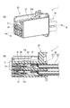
以下、図面を参照しながら、本発明の実施形態に係る端子金具10を用いた、端子金具10とハウジング20との係合構造1について説明する。以下、説明の便宜上、端子金具10の軸方向(嵌合方向)において、相手側端子(図示省略)が嵌合する側(図1〜図4において左側)を先端側(前方側)とし、その反対側(図1〜図4において右側)を基端側(後方側)と呼ぶ。また、図1〜図4において上側及び下側をそれぞれ、上側及び下側と呼ぶ。
なお、本発明は上記各実施形態に限定されることはなく、本発明の範囲内において種々の変形例を採用することができる。例えば、本発明は、上述した実施形態に限定されるものではなく、適宜、変形、改良、等が可能である。その他、上述した実施形態における各構成要素の材質、形状、寸法、数、配置箇所、等は本発明を達成できるものであれば任意であり、限定されない。
(1)
相手側端子を受け入れる筒状の箱部(11)と、
前記相手側端子に押圧接触するように前記箱部(11)の内壁から延びる端子バネ(16)と、
前記端子バネ(16)と前記相手側端子とが接触しているときの前記端子バネ(16)の変形を所定範囲内に規制する変形規制部(17)であって、前記端子バネ(16)との接触箇所が面取り(17a)されている変形規制部(17)と、を備える、
端子金具(10)。
(2)
上記(1)に記載の端子金具(10)であって、
前記箱部(11)の内側に向けて突出する形状を有し、前記端子バネ(16)が前記相手側端子に押圧接触するときの支点(15a)として働く支点部(15)、を更に備え、
前記端子バネ(16)は、
片持ち梁状の形状を有し、
前記変形規制部(17)は、
前記支点部(15)よりも前記端子バネ(16)の自由端に近い位置にて前記端子バネ(16)に接触することで、前記端子バネ(16)の変形を所定範囲内に規制する、
端子金具(10)。
11 箱部
15 支点部
15a 先端部(支点)
16 端子バネ
17 貫通孔の基端側縁(変形規制部)
17a 面取り部(面取り)
Claims (2)
- 相手側端子を受け入れる筒状の箱部と、
前記相手側端子に押圧接触するように前記箱部の内壁から延びる端子バネと、
前記端子バネと前記相手側端子とが接触しているときの前記端子バネの変形を所定範囲内に規制する変形規制部であって、前記端子バネとの接触箇所が面取りされている変形規制部と、を備える、
端子金具。 - 請求項1に記載の端子金具であって、
前記箱部の内側に向けて突出する形状を有し、前記端子バネが前記相手側端子に押圧接触するときの支点として働く支点部、を更に備え、
前記端子バネは、
片持ち梁状の形状を有し、
前記変形規制部は、
前記支点部よりも前記端子バネの自由端に近い位置にて前記端子バネに接触することで、前記端子バネの変形を所定範囲内に規制する、
端子金具。
Priority Applications (4)
| Application Number | Priority Date | Filing Date | Title |
|---|---|---|---|
| JP2018121087A JP6782736B2 (ja) | 2018-06-26 | 2018-06-26 | 端子金具 |
| EP19175823.4A EP3588687B1 (en) | 2018-06-26 | 2019-05-22 | Terminal metal fitting |
| US16/419,646 US11088483B2 (en) | 2018-06-26 | 2019-05-22 | Terminal metal fitting with spring contact and spring contact deformation restriction portion |
| CN201910437730.0A CN110649410B (zh) | 2018-06-26 | 2019-05-24 | 端子金属配件 |
Applications Claiming Priority (1)
| Application Number | Priority Date | Filing Date | Title |
|---|---|---|---|
| JP2018121087A JP6782736B2 (ja) | 2018-06-26 | 2018-06-26 | 端子金具 |
Publications (2)
| Publication Number | Publication Date |
|---|---|
| JP2020004539A true JP2020004539A (ja) | 2020-01-09 |
| JP6782736B2 JP6782736B2 (ja) | 2020-11-11 |
Family
ID=66630176
Family Applications (1)
| Application Number | Title | Priority Date | Filing Date |
|---|---|---|---|
| JP2018121087A Active JP6782736B2 (ja) | 2018-06-26 | 2018-06-26 | 端子金具 |
Country Status (4)
| Country | Link |
|---|---|
| US (1) | US11088483B2 (ja) |
| EP (1) | EP3588687B1 (ja) |
| JP (1) | JP6782736B2 (ja) |
| CN (1) | CN110649410B (ja) |
Cited By (1)
| Publication number | Priority date | Publication date | Assignee | Title |
|---|---|---|---|---|
| WO2022249691A1 (ja) * | 2021-05-28 | 2022-12-01 | 株式会社オートネットワーク技術研究所 | 基板用コネクタ |
Families Citing this family (1)
| Publication number | Priority date | Publication date | Assignee | Title |
|---|---|---|---|---|
| JP6865198B2 (ja) * | 2018-07-17 | 2021-04-28 | 矢崎総業株式会社 | 端子 |
Citations (7)
| Publication number | Priority date | Publication date | Assignee | Title |
|---|---|---|---|---|
| JPH0785918A (ja) * | 1993-09-14 | 1995-03-31 | Yazaki Corp | 電気接続子 |
| JPH10233251A (ja) * | 1997-02-13 | 1998-09-02 | Siemens Ag | 一体構成の接触ばね |
| JPH11233181A (ja) * | 1998-02-13 | 1999-08-27 | Sumitomo Wiring Syst Ltd | 雌側端子金具 |
| JP2006100232A (ja) * | 2004-09-29 | 2006-04-13 | Sumitomo Wiring Syst Ltd | 端子金具及びこれを用いたコネクタ |
| JP2009252495A (ja) * | 2008-04-04 | 2009-10-29 | Sumitomo Wiring Syst Ltd | 端子金具 |
| JP2012089318A (ja) * | 2010-10-19 | 2012-05-10 | Sumitomo Wiring Syst Ltd | 端子金具 |
| JP5682520B2 (ja) * | 2011-09-14 | 2015-03-11 | 住友電装株式会社 | 端子金具 |
Family Cites Families (9)
| Publication number | Priority date | Publication date | Assignee | Title |
|---|---|---|---|---|
| US5217382A (en) * | 1992-06-05 | 1993-06-08 | Interlock Corporation | Electric receptacle with shape memory spring member |
| US5593328A (en) * | 1993-11-04 | 1997-01-14 | Sumitomo Wiring Systems, Ltd. | Female terminal fitting for connector |
| WO1998018181A1 (en) | 1996-10-17 | 1998-04-30 | The Whitaker Corporation | Electrical connector having a housing and an electrical contact and electrical contact |
| JP3576488B2 (ja) * | 2000-12-18 | 2004-10-13 | 日本圧着端子製造株式会社 | 雌端子 |
| EP1643599B1 (en) | 2004-09-29 | 2008-12-17 | Sumitomo Wiring Systems, Ltd. | A terminal fitting and a connector using such a terminal fitting |
| JP5723133B2 (ja) | 2010-10-12 | 2015-05-27 | 矢崎総業株式会社 | 雌型端子金具 |
| JP2014170709A (ja) | 2013-03-05 | 2014-09-18 | Sumitomo Wiring Syst Ltd | 雌端子金具 |
| JP5958394B2 (ja) * | 2013-03-21 | 2016-08-02 | 住友電装株式会社 | 端子金具 |
| JP6209356B2 (ja) | 2013-04-26 | 2017-10-04 | 矢崎総業株式会社 | コネクタ |
-
2018
- 2018-06-26 JP JP2018121087A patent/JP6782736B2/ja active Active
-
2019
- 2019-05-22 EP EP19175823.4A patent/EP3588687B1/en active Active
- 2019-05-22 US US16/419,646 patent/US11088483B2/en active Active
- 2019-05-24 CN CN201910437730.0A patent/CN110649410B/zh active Active
Patent Citations (7)
| Publication number | Priority date | Publication date | Assignee | Title |
|---|---|---|---|---|
| JPH0785918A (ja) * | 1993-09-14 | 1995-03-31 | Yazaki Corp | 電気接続子 |
| JPH10233251A (ja) * | 1997-02-13 | 1998-09-02 | Siemens Ag | 一体構成の接触ばね |
| JPH11233181A (ja) * | 1998-02-13 | 1999-08-27 | Sumitomo Wiring Syst Ltd | 雌側端子金具 |
| JP2006100232A (ja) * | 2004-09-29 | 2006-04-13 | Sumitomo Wiring Syst Ltd | 端子金具及びこれを用いたコネクタ |
| JP2009252495A (ja) * | 2008-04-04 | 2009-10-29 | Sumitomo Wiring Syst Ltd | 端子金具 |
| JP2012089318A (ja) * | 2010-10-19 | 2012-05-10 | Sumitomo Wiring Syst Ltd | 端子金具 |
| JP5682520B2 (ja) * | 2011-09-14 | 2015-03-11 | 住友電装株式会社 | 端子金具 |
Cited By (1)
| Publication number | Priority date | Publication date | Assignee | Title |
|---|---|---|---|---|
| WO2022249691A1 (ja) * | 2021-05-28 | 2022-12-01 | 株式会社オートネットワーク技術研究所 | 基板用コネクタ |
Also Published As
| Publication number | Publication date |
|---|---|
| EP3588687A1 (en) | 2020-01-01 |
| US20190393637A1 (en) | 2019-12-26 |
| EP3588687B1 (en) | 2021-11-03 |
| US11088483B2 (en) | 2021-08-10 |
| JP6782736B2 (ja) | 2020-11-11 |
| CN110649410B (zh) | 2020-12-29 |
| CN110649410A (zh) | 2020-01-03 |
Similar Documents
| Publication | Publication Date | Title |
|---|---|---|
| US7255611B2 (en) | Connector | |
| JP4427564B2 (ja) | コネクタプラグ | |
| WO2012127541A1 (ja) | 電線対基板コネクタ | |
| US20090275245A1 (en) | Electrical connector with improved contacts | |
| JP4175657B2 (ja) | コネクタ | |
| JPH07296873A (ja) | 雌型コンタクト | |
| JP5754533B1 (ja) | コネクタ端子およびコネクタ | |
| JP2016051689A (ja) | コネクタ端子 | |
| JP2020042914A (ja) | 端子金具 | |
| JP2020004539A (ja) | 端子金具 | |
| JP2015204186A (ja) | 端子 | |
| JP2009176580A (ja) | ジャック型コネクタ | |
| JP2020004538A (ja) | 端子金具、及び、端子金具とハウジングとの係合構造 | |
| US9124017B2 (en) | Terminal fitting | |
| JP7405566B2 (ja) | 端子金具、及び、コネクタ構造 | |
| JP2020135998A (ja) | コネクタ | |
| JP5821831B2 (ja) | コネクタ | |
| JP4446477B2 (ja) | コネクタ | |
| JP6331273B2 (ja) | コネクタ | |
| US10892582B2 (en) | Connector with upper and lower covers | |
| JP2013089421A (ja) | コネクタ | |
| JP2018037190A (ja) | 平型導体用電気コネクタ | |
| JP2007095395A (ja) | 電気コネクタハウジング | |
| JP2004139756A (ja) | 端子金具及びバルブソケット | |
| JP2016024894A (ja) | 端子 |
Legal Events
| Date | Code | Title | Description |
|---|---|---|---|
| A621 | Written request for application examination |
Free format text: JAPANESE INTERMEDIATE CODE: A621 Effective date: 20190819 |
|
| A977 | Report on retrieval |
Free format text: JAPANESE INTERMEDIATE CODE: A971007 Effective date: 20200709 |
|
| A131 | Notification of reasons for refusal |
Free format text: JAPANESE INTERMEDIATE CODE: A131 Effective date: 20200714 |
|
| A521 | Request for written amendment filed |
Free format text: JAPANESE INTERMEDIATE CODE: A523 Effective date: 20200909 |
|
| TRDD | Decision of grant or rejection written | ||
| A01 | Written decision to grant a patent or to grant a registration (utility model) |
Free format text: JAPANESE INTERMEDIATE CODE: A01 Effective date: 20201013 |
|
| A61 | First payment of annual fees (during grant procedure) |
Free format text: JAPANESE INTERMEDIATE CODE: A61 Effective date: 20201020 |
|
| R150 | Certificate of patent or registration of utility model |
Ref document number: 6782736 Country of ref document: JP Free format text: JAPANESE INTERMEDIATE CODE: R150 |
|
| S531 | Written request for registration of change of domicile |
Free format text: JAPANESE INTERMEDIATE CODE: R313531 |
|
| R350 | Written notification of registration of transfer |
Free format text: JAPANESE INTERMEDIATE CODE: R350 |
|
| R250 | Receipt of annual fees |
Free format text: JAPANESE INTERMEDIATE CODE: R250 |