JP2018528362A - Disc brake and brake pad set for commercial vehicles - Google Patents
Disc brake and brake pad set for commercial vehicles Download PDFInfo
- Publication number
- JP2018528362A JP2018528362A JP2017564455A JP2017564455A JP2018528362A JP 2018528362 A JP2018528362 A JP 2018528362A JP 2017564455 A JP2017564455 A JP 2017564455A JP 2017564455 A JP2017564455 A JP 2017564455A JP 2018528362 A JP2018528362 A JP 2018528362A
- Authority
- JP
- Japan
- Prior art keywords
- brake
- support plate
- spring
- lining support
- lining
- Prior art date
- Legal status (The legal status is an assumption and is not a legal conclusion. Google has not performed a legal analysis and makes no representation as to the accuracy of the status listed.)
- Granted
Links
Images

Classifications
-
- F—MECHANICAL ENGINEERING; LIGHTING; HEATING; WEAPONS; BLASTING
- F16—ENGINEERING ELEMENTS AND UNITS; GENERAL MEASURES FOR PRODUCING AND MAINTAINING EFFECTIVE FUNCTIONING OF MACHINES OR INSTALLATIONS; THERMAL INSULATION IN GENERAL
- F16D—COUPLINGS FOR TRANSMITTING ROTATION; CLUTCHES; BRAKES
- F16D55/00—Brakes with substantially-radial braking surfaces pressed together in axial direction, e.g. disc brakes
- F16D55/02—Brakes with substantially-radial braking surfaces pressed together in axial direction, e.g. disc brakes with axially-movable discs or pads pressed against axially-located rotating members
- F16D55/22—Brakes with substantially-radial braking surfaces pressed together in axial direction, e.g. disc brakes with axially-movable discs or pads pressed against axially-located rotating members by clamping an axially-located rotating disc between movable braking members, e.g. movable brake discs or brake pads
- F16D55/224—Brakes with substantially-radial braking surfaces pressed together in axial direction, e.g. disc brakes with axially-movable discs or pads pressed against axially-located rotating members by clamping an axially-located rotating disc between movable braking members, e.g. movable brake discs or brake pads with a common actuating member for the braking members
- F16D55/225—Brakes with substantially-radial braking surfaces pressed together in axial direction, e.g. disc brakes with axially-movable discs or pads pressed against axially-located rotating members by clamping an axially-located rotating disc between movable braking members, e.g. movable brake discs or brake pads with a common actuating member for the braking members the braking members being brake pads
- F16D55/226—Brakes with substantially-radial braking surfaces pressed together in axial direction, e.g. disc brakes with axially-movable discs or pads pressed against axially-located rotating members by clamping an axially-located rotating disc between movable braking members, e.g. movable brake discs or brake pads with a common actuating member for the braking members the braking members being brake pads in which the common actuating member is moved axially, e.g. floating caliper disc brakes
-
- F—MECHANICAL ENGINEERING; LIGHTING; HEATING; WEAPONS; BLASTING
- F16—ENGINEERING ELEMENTS AND UNITS; GENERAL MEASURES FOR PRODUCING AND MAINTAINING EFFECTIVE FUNCTIONING OF MACHINES OR INSTALLATIONS; THERMAL INSULATION IN GENERAL
- F16D—COUPLINGS FOR TRANSMITTING ROTATION; CLUTCHES; BRAKES
- F16D65/00—Parts or details
- F16D65/005—Components of axially engaging brakes not otherwise provided for
- F16D65/0068—Brake calipers
-
- F—MECHANICAL ENGINEERING; LIGHTING; HEATING; WEAPONS; BLASTING
- F16—ENGINEERING ELEMENTS AND UNITS; GENERAL MEASURES FOR PRODUCING AND MAINTAINING EFFECTIVE FUNCTIONING OF MACHINES OR INSTALLATIONS; THERMAL INSULATION IN GENERAL
- F16D—COUPLINGS FOR TRANSMITTING ROTATION; CLUTCHES; BRAKES
- F16D65/00—Parts or details
- F16D65/02—Braking members; Mounting thereof
- F16D65/04—Bands, shoes or pads; Pivots or supporting members therefor
- F16D65/092—Bands, shoes or pads; Pivots or supporting members therefor for axially-engaging brakes, e.g. disc brakes
- F16D65/095—Pivots or supporting members therefor
- F16D65/097—Resilient means interposed between pads and supporting members or other brake parts
- F16D65/0973—Resilient means interposed between pads and supporting members or other brake parts not subjected to brake forces
- F16D65/0974—Resilient means interposed between pads and supporting members or other brake parts not subjected to brake forces acting on or in the vicinity of the pad rim in a direction substantially transverse to the brake disc axis
- F16D65/0977—Springs made from sheet metal
-
- F—MECHANICAL ENGINEERING; LIGHTING; HEATING; WEAPONS; BLASTING
- F16—ENGINEERING ELEMENTS AND UNITS; GENERAL MEASURES FOR PRODUCING AND MAINTAINING EFFECTIVE FUNCTIONING OF MACHINES OR INSTALLATIONS; THERMAL INSULATION IN GENERAL
- F16D—COUPLINGS FOR TRANSMITTING ROTATION; CLUTCHES; BRAKES
- F16D65/00—Parts or details
- F16D65/14—Actuating mechanisms for brakes; Means for initiating operation at a predetermined position
- F16D65/16—Actuating mechanisms for brakes; Means for initiating operation at a predetermined position arranged in or on the brake
- F16D65/18—Actuating mechanisms for brakes; Means for initiating operation at a predetermined position arranged in or on the brake adapted for drawing members together, e.g. for disc brakes
- F16D65/183—Actuating mechanisms for brakes; Means for initiating operation at a predetermined position arranged in or on the brake adapted for drawing members together, e.g. for disc brakes with force-transmitting members arranged side by side acting on a spot type force-applying member
-
- F—MECHANICAL ENGINEERING; LIGHTING; HEATING; WEAPONS; BLASTING
- F16—ENGINEERING ELEMENTS AND UNITS; GENERAL MEASURES FOR PRODUCING AND MAINTAINING EFFECTIVE FUNCTIONING OF MACHINES OR INSTALLATIONS; THERMAL INSULATION IN GENERAL
- F16D—COUPLINGS FOR TRANSMITTING ROTATION; CLUTCHES; BRAKES
- F16D65/00—Parts or details
- F16D65/38—Slack adjusters
- F16D65/40—Slack adjusters mechanical
- F16D65/52—Slack adjusters mechanical self-acting in one direction for adjusting excessive play
- F16D65/54—Slack adjusters mechanical self-acting in one direction for adjusting excessive play by means of direct linear adjustment
-
- F—MECHANICAL ENGINEERING; LIGHTING; HEATING; WEAPONS; BLASTING
- F16—ENGINEERING ELEMENTS AND UNITS; GENERAL MEASURES FOR PRODUCING AND MAINTAINING EFFECTIVE FUNCTIONING OF MACHINES OR INSTALLATIONS; THERMAL INSULATION IN GENERAL
- F16D—COUPLINGS FOR TRANSMITTING ROTATION; CLUTCHES; BRAKES
- F16D55/00—Brakes with substantially-radial braking surfaces pressed together in axial direction, e.g. disc brakes
- F16D2055/0004—Parts or details of disc brakes
- F16D2055/0016—Brake calipers
- F16D2055/0029—Retraction devices
Landscapes
- Engineering & Computer Science (AREA)
- General Engineering & Computer Science (AREA)
- Mechanical Engineering (AREA)
- Braking Arrangements (AREA)
Abstract
ブレーキディスク(2)に跨がる、摺動キャリパとして形成されるブレーキキャリパ(1)を備えるディスクブレーキ(10)は、ブレーキキャリパ(1)内に配置された2つの、互いに反対方向に可動なブレーキパッド(3,3’)であって、それぞれ、ライニング支持プレート(4)と、ライニング支持プレート(4)に取り付けられた摩擦ライニング(5)とを有し、ブレーキパッド(3,3’)のうちの一方の作用側あるいは作動側のブレーキパッド(3)は、作動装置により少なくとも1つのブレーキピストンを介してブレーキディスク(2)に圧着可能であるブレーキパッド(3,3’)と、ブレーキキャリパ(1)を制動に起因するブレーキキャリパ(1)の移動およびブレーキの解除後に戻すことが可能な少なくとも1つの戻し装置であって、対向するブレーキパッド(3)に作用する、それぞれの作動方向とは反対方向に同様に作用する拡開装置(8)を有し、拡開装置(8)は、それぞれのライニング支持プレート(4)に作用するばね式の拡開要素を有する戻し装置と、を備える。拡開装置(8)は、中央の開口(9)内に配置されており、拡開要素は、摩擦ライニング(5)外で、ブレーキパッド(3)の、中央に関して互いに間隔を置いて配置された少なくとも2つの当接領域に直接的または間接的に作用し、当接領域は、それぞれ、当接面と載置面(4c)とを有し、当接面および載置面(4c)に拡開要素は可動に配置されている。相応のブレーキパッドセットも提供する。A disc brake (10) comprising a brake caliper (1) formed as a sliding caliper straddling the brake disc (2) is movable in two opposite directions arranged in the brake caliper (1). Brake pads (3, 3 ') each having a lining support plate (4) and a friction lining (5) attached to the lining support plate (4), the brake pads (3, 3') The brake pad (3) on one working side or the working side of the brake pad (3, 3 ') that can be crimped to the brake disc (2) via at least one brake piston by the actuating device, and the brake At least one caliper (1) that can be returned after the brake caliper (1) has been moved and released due to braking And a spreading device (8) acting on the opposite brake pad (3) and acting in the opposite direction to the respective operating direction. The spreading device (8) And a return device having a spring-type spreading element acting on the lining support plate (4). The spreading device (8) is arranged in the central opening (9) and the spreading elements are spaced apart from each other with respect to the center of the brake pad (3) outside the friction lining (5). The contact area directly or indirectly acts on at least two contact areas, and each of the contact areas has an abutment surface and a placement surface (4c), and the abutment surface and the placement surface (4c). The spreading element is movably arranged. Corresponding brake pad sets are also provided.
Description
本発明は、請求項1の前提部に記載の商用車用のディスクブレーキに関する。本発明は、ブレーキパッドセットにも関する。 The present invention relates to a commercial vehicle disc brake according to the premise of claim 1. The present invention also relates to a brake pad set.
この種の、摺動キャリパ(Schiebesattel)型ブレーキとしても公知のディスクブレーキの場合、制動時、空気圧または電動モータにより操作可能な作動装置を用いて、作用側のブレーキパッドを車両側のブレーキディスクに押し付ける。制動プロセスの以後の経過中、ブレーキキャリパは、ブレーキディスクに関して作用側のブレーキパッドの作動方向とは反対方向に移動して、対向する反作用側のブレーキパッドを連れ動かし、ブレーキディスクの他方の面に圧着させる。 In the case of a disc brake known also as this kind of sliding caliper type brake, a brake pad on the working side is used as a brake disc on the vehicle side by using an operating device that can be operated by a pneumatic or electric motor during braking. Press. During the subsequent course of the braking process, the brake caliper moves in the direction opposite to the operating direction of the working brake pad with respect to the brake disc, and moves the opposing reaction brake pad along the other side of the brake disc. Crimp.
ブレーキの解除後、公知のディスクブレーキの場合、ブレーキキャリパは、両ブレーキパッドのうちの少なくとも反作用側のブレーキパッドが、確かに無圧とはいえ、ブレーキディスクに引きずり接触してしまう位置にとどまる。これにより走行運転中に発生するブレーキパッドの残留引きずりトルクは、燃料消費量を上昇させるとともに、関連する構成部材、すなわちブレーキディスクおよびブレーキパッドの耐用時間を短縮させてしまうという点において不都合に働く。 After releasing the brake, in the case of a known disc brake, the brake caliper remains in a position where at least the reaction-side brake pad of both brake pads is in drag contact with the brake disc, although it is certainly no pressure. As a result, the residual drag torque of the brake pad generated during the driving operation is disadvantageous in that it increases the fuel consumption and shortens the service life of the related components, that is, the brake disc and the brake pad.
確かにブレーキパッドは、走行運転中、例えばブレーキディスクの振れおよび振動ならびにカーブ走行時の横加速度により多少は解離される。しかし、この効果は、上述の残留引きずりトルクを効果的に防止するには十分とはいえない。 Certainly, the brake pad is somewhat dissociated during running operation, for example, due to vibration and vibration of the brake disc and lateral acceleration during curve running. However, this effect is not sufficient to effectively prevent the above-mentioned residual drag torque.
この問題を解消すべく、下記特許文献1に開示されるこの種のディスクブレーキは、戻し装置を備える。戻し装置は、ブレーキキャリパを移動自在にブレーキ支持体に保持する複数のガイドバーのうちの1つのガイドバー内に配置されており、ブレーキキャリパを初期位置へ移動させるばね式の戻し要素を有している。 In order to solve this problem, this type of disc brake disclosed in Patent Document 1 below includes a return device. The return device is disposed in one of a plurality of guide bars that hold the brake caliper on the brake support body movably, and has a spring-type return element that moves the brake caliper to an initial position. ing.
原則、この設計は、実証されている。しかし、この公知の戻し装置を、より重量のある商用車の圧縮空気操作式のディスクブレーキにおいて使用することは、問題を招くことがある。それというのも、このような商用車の圧縮空気操作式のディスクブレーキでは、構成部材公差および構成部材変形による影響の変動が、広範に及んでしまい、このことは、この戻し装置の確実な機能を時として不可能にしてしまうことがあるからである。 In principle, this design has been proven. However, the use of this known return device in a heavier commercial vehicle compressed air operated disc brake can be problematic. This is because in commercial vehicle compressed air operated disc brakes, fluctuations in the effects of component tolerances and component deformations are widespread, which is a reliable function of the return device. Because it sometimes makes it impossible.
同等の問題は、下記特許文献2において主題として扱われているディスクブレーキでも生じてしまう。このディスクブレーキの場合、戻し装置は、作動装置に対向した、反作用側のブレーキパッド寄りの側に配置されており、これにより、ブレーキキャリパの効果的な、特に自動的な戻しが達成されると同時に、系の剛性への影響は最小限になる。
The same problem also occurs in the disc brake treated as the subject in
いずれにしても戻し装置は、ブレーキキャリパに作用し、ブレーキ支持体は、サポートとして機能している。 In any case, the return device acts on the brake caliper, and the brake support functions as a support.
下記特許文献3に記載の浮動キャリパ(Schwimmsattel)型ディスクブレーキは、ブレーキディスクの外側の縁部を越えて張り出した2つの支持腕を有する不動のブレーキ支持体と、ブレーキディスクの両側に配置され、それぞれ1つの摩擦ライニングと1つのバックプレートとを有するブレーキジョーであって、支持腕に移動自在に支持されているブレーキジョーと、ブレーキ支持体に沿って軸方向で移動自在に案内される浮動キャリパであって、ブレーキジョーを抱持し、ブレーキジョーをブレーキディスクに押し当てるための操作装置を有する浮動キャリパと、ブレーキジョーに対して軸方向のブレーキ解除方向で作用するばね装置であって、制動後、ブレーキジョーとブレーキディスクとの間の空隙の調整を補助するばね装置と、を備える。ばね装置は、少なくとも1つの拡開ばねを有し、拡開ばねは、ブレーキ支持体の支持腕に軸方向で全体的に移動不能に取り付けられており、この取り付けは、支持腕の、ブレーキディスクの外側の縁部を越えて存在する部分で実施され、かつ拡開ばねは、少なくとも2つのばね腕を有し、ばね腕は、ブレーキジョーのバックプレートに軸方向で弾性的に当接している。
The floating caliper (Schwimmsattel) type disc brake described in
下記特許文献4に記載の拡開ばねは、拡開ばねをブレーキコンポーネントに結合する係止腕と、引き戻し腕と、係止腕と引き戻し腕との間に配置されているプリロード装置であって、螺旋形の6つ以上のループを有し、ブレーキ動作中、エネルギを蓄え、制動プロセスが終了すると直ちに、ブレーキコンポーネント(ブレーキパッド)を引き戻すプリロード装置と、を有する。摺動キャリパではないフローティングキャリパ(Faustsattel)の形態のブレーキキャリパが記載されている。このブレーキキャリパは、乗用車には好適であるが、商用車には不適である。
The expansion spring described in the following
本発明の根底にある課題は、この種の形態のディスクブレーキを改良し、構造的に最も簡単な手段を用いて耐用時間、特にブレーキパッドおよびブレーキディスクの耐用時間を延ばし、運転コストを全体として引き下げることである。 The problem underlying the present invention is to improve a disc brake of this type, to extend the service life, in particular the service life of the brake pads and brake discs, using the simplest structural means, and to reduce the operating costs as a whole. To lower.
別の課題は、相応のブレーキパッドセットを提供することである。 Another problem is to provide a corresponding brake pad set.
上記課題は、請求項1の特徴を備えるディスクブレーキにより解決される。 The object is solved by a disc brake having the features of claim 1.
上記別の課題は、請求項34の特徴を備えるブレーキパッドセットにより解決される。
Said another problem is solved by a brake pad set comprising the features of
商用車用の本発明に係るディスクブレーキは、ブレーキディスクに跨がる、摺動キャリパとして形成されるブレーキキャリパであって、不動のブレーキ支持体に取り付けられており、中央の開口をブレーキディスクの上方に有するブレーキキャリパと、ブレーキキャリパ内に配置された2つの、互いに反対方向に可動なブレーキパッドであって、それぞれ、ライニング支持プレートと、ライニング支持プレートに取り付けられた摩擦ライニングとを有し、ブレーキパッドのうちの一方の作用側あるいは作動側のブレーキパッドは、作動装置により少なくとも1つのブレーキピストンを介してブレーキディスクに圧着可能であるブレーキパッドと、ブレーキキャリパを制動に起因するブレーキキャリパの移動およびブレーキの解除後に戻すことが可能な少なくとも1つの戻し装置であって、対向するブレーキパッドに作用する、それぞれの作動方向とは反対方向に同様に作用する拡開装置を有し、拡開装置は、それぞれのライニング支持プレートに作用するばね式の拡開要素を有する戻し装置と、を備える。拡開装置は、中央の開口内に配置されており、拡開要素は、摩擦ライニング外で、ブレーキパッドの、中央に関して互いに間隔を置いて配置された少なくとも2つの当接領域に直接的または間接的に作用し、当接領域は、それぞれ、当接面と載置面とを有し、当接面および載置面に拡開要素は可動に配置されている。 A disc brake according to the present invention for a commercial vehicle is a brake caliper formed as a sliding caliper that straddles the brake disc, and is attached to an immobile brake support. An upper brake caliper, and two brake pads disposed in the brake caliper that are movable in opposite directions, each having a lining support plate and a friction lining attached to the lining support plate; One of the brake pads on the working side or the brake pad on the working side includes a brake pad that can be crimped to the brake disc via at least one brake piston by the actuating device, and movement of the brake caliper caused by braking the brake caliper. And return after releasing the brake At least one possible return device, having a spreading device acting on the opposite brake pad, acting in the opposite direction to the respective operating direction, the spreading device being on each lining support plate And a return device having a spring-type spreading element that acts. The spreading device is arranged in the central opening, and the spreading element is directly or indirectly outside the friction lining and at least two abutment regions spaced from each other with respect to the center of the brake pad. Each of the contact regions has a contact surface and a mounting surface, and the spreading element is movably disposed on the contact surface and the mounting surface.
ディスクブレーキを本発明のように構成したことで、ブレーキの解除時、両ブレーキパッドの同期的な戻しと、ブレーキキャリパの戻しとが達成される。ここでいう同期性は、戻し力にも、戻し行程にも関する。その際、戻し力は、両ブレーキパッドのそれぞれの作動方向とは反対方向に、つまり、反作用側のブレーキパッドの場合は、キャリパ背部に向かって、そして作用側のブレーキパッドの場合は、キャリパヘッドに向かって作用し、ブレーキディスクに対して間隙を形成する。 By configuring the disc brake as in the present invention, when the brake is released, both the brake pads can be returned synchronously and the brake caliper can be returned. Synchronism here relates to both the return force and the return stroke. In this case, the return force is in the direction opposite to the direction of actuation of the two brake pads, i.e. towards the back of the caliper in the case of the reaction side brake pad and to the caliper head in the case of the action side brake pad. To form a gap with respect to the brake disc.
両ブレーキパッドにおける拡開装置の作用は、合目的にライニング支持プレートにおいて、具体的には、ライニング支持プレートに取り付けられた摩擦ライニング側の面または反対側の背面で実施される。戻し時にそれぞれのブレーキパッドが傾倒してしまわないように、拡開要素は、中央で、ライニング支持プレートの上側の露出した縁部領域に作用するか、または左右2つの当接領域に対称に作用する。 The action of the spreading device on both brake pads is carried out on the lining support plate for the purpose, specifically on the friction lining side surface attached to the lining support plate or on the opposite back surface. The spreading element acts in the middle on the exposed edge area on the upper side of the lining support plate or symmetrically on the two left and right contact areas so that the respective brake pads do not tilt when returning To do.
本発明に係るディスクブレーキ用の本発明に係るブレーキパッドセットは、それぞれライニング支持プレートと、ライニング支持プレートに取着された摩擦ライニングとを有する少なくとも2つのブレーキパッドと、上述の拡開装置と、を備える。ライニング支持プレートは、片面の摩擦ライニング外において、中央領域に、または中央に関して互いに間隔を置いて配置された少なくとも2つの当接領域に、それぞれ、当接面と載置面とを有する。これにより、複数の機能(軸方向および半径方向のばね力伝達、ばね端部案内)が狭小な空間で実現されるという利点が生じる。 A brake pad set according to the present invention for a disc brake according to the present invention includes at least two brake pads each having a lining support plate and a friction lining attached to the lining support plate, and the above-described spreading device, Is provided. The lining support plate has an abutment surface and a mounting surface, respectively, in the central region or in at least two abutment regions spaced from each other with respect to the center outside the one-side friction lining. This has the advantage that a plurality of functions (axial and radial spring force transmission, spring end guide) are realized in a narrow space.
一形態において、拡開要素は、開口の中央にある中央の領域を起点に内から外に、中央に関して互いに間隔を置いて配置された当接領域に向かって延在する。拡開要素は、開口の中央にある中央の領域を起点に内から外に、中央に関して等しく互いに間隔を置いて配置された当接領域に向かって延在してもよい。 In one form, the spreading element extends from inside to outside starting from a central area at the center of the opening and toward abutting areas spaced from each other with respect to the center. The spreading element may extend from inside to outside starting from a central area in the center of the opening, towards an abutment area that is equally spaced from the center.
こうして拡開装置は、ブレーキキャリパの中央に配置されている。拡開装置は同じく、対応する車輪のリムの包絡線内に配置されている。 Thus, the spreading device is arranged at the center of the brake caliper. The spreading device is likewise arranged in the envelope of the corresponding wheel rim.
両拡開要素は、(支持体凸部に関して)中央で互いに結合されている。これにより、小さな公差範囲内で同じばね力が、回入側でも、回出側でも保証され得る。回出側と回入側との間の異なるばね力は、偏摩耗に至らしめるおそれがあるが、パッド毎に1つのばねが片面で作用することで最小化される。 Both spreading elements are connected to each other in the middle (with respect to the support projection). As a result, the same spring force within a small tolerance range can be ensured on both the entry and exit sides. Different spring forces between the delivery side and the entry side can lead to uneven wear, but are minimized by the action of one spring per pad on one side.
別の一形態において、開口の中央の領域は、ブレーキディスクの平面に対して略平行に開口のバーチャルな中心の両側に開口の長手方向軸線の30〜50%の範囲の長さで延在する。これにより、ばね力の有利な適合が得られる。 In another form, the central region of the opening extends for a length in the range of 30-50% of the longitudinal axis of the opening on either side of the virtual center of the opening substantially parallel to the plane of the brake disc. . This provides an advantageous adaptation of the spring force.
別の一形態において、拡開装置は、複数のばね腕を有し、ばね腕のうちのそれぞれ2つは、対応する1つのライニング支持プレートに当接し、ばね腕は、開口の中央の領域で互いに結合されている。このことは、組み立ておよび保守時の組み込みを容易にする。 In another form, the spreading device has a plurality of spring arms, each two of the spring arms abut against a corresponding one of the lining support plates, and the spring arms are in the central region of the opening. Are connected to each other. This facilitates assembly during assembly and maintenance.
本発明の別の一思想によれば、拡開装置は、互いに反対方向に作用する複数の拡開要素、好ましくは弾性的に作用する特にばね要素の形態の拡開要素を有する。 According to another idea of the invention, the spreading device has a plurality of spreading elements acting in opposite directions, preferably spreading elements, preferably in the form of spring elements, which act elastically.
本発明の一思想によれば、拡開装置は、サポートを形成するブレーキ支持体であって、その内部にブレーキパッドがブレーキディスクに対して同軸に移動自在に支持されたブレーキ支持体と相互作用関係にある。 According to one aspect of the invention, the spreading device is a brake support that forms a support and interacts with a brake support in which a brake pad is supported coaxially with respect to a brake disc. There is a relationship.
これに加え、好ましくは、保持アーチが設けられており、保持アーチは、ブレーキディスクに、ブレーキ支持体の、両側でパッドチャネルを画定するブレーキ支持体凸部までの周方向領域で張り渡されているとともに、ブレーキディスクの厚さに関してブレーキディスクの中央に配置されている。保持アーチは、パッド保持ヨークではなく、付加的な構成部材である。 In addition to this, preferably a holding arch is provided, the holding arch being stretched over the brake disc in the circumferential region to the brake support convexity defining the pad channel on both sides of the brake support. In addition, the thickness of the brake disc is arranged at the center of the brake disc. The holding arch is not a pad holding yoke but an additional component.
保持アーチは、一形態において、対向する2つの、ブレーキ支持体に結合されるヨークに接続されていてもよい。このことは、簡単な結合を実現する。 In one form, the holding arch may be connected to two opposing yokes coupled to the brake support. This realizes a simple coupling.
あるいは保持アーチが、1つのパッドチャネルの少なくとも2つのブレーキ支持体凸部に接続されていてもよく、両ブレーキパッドに作用する拡開要素は、保持アーチに結合されている。これにより保持アーチは、センタリング装置を形成する。センタリング装置は、固定のマウンティングとしてのブレーキ支持体に対応して構造的に異なって実現されてもよい。 Alternatively, the holding arch may be connected to at least two brake support protrusions of one pad channel, and the spreading elements acting on both brake pads are coupled to the holding arch. Thereby, the holding arch forms a centering device. The centering device may be realized structurally differently corresponding to the brake support as a fixed mounting.
好ましくは、保持アーチは、C字形の輪郭をなして、ブレーキディスクに上述の寸法で張り渡される1つの中央脚片と、中央脚片に対して同じ方向に方向付けられ、ブレーキ支持体凸部に向かって曲げられた2つの端部脚片とを有して形成されており、端部脚片のうちのそれぞれ1つの端部脚片は、対応するパッドチャネルのブレーキ支持体凸部に取り付けられている。 Preferably, the retaining arch has a C-shaped profile and is oriented in the same direction with respect to the central leg piece, with one central leg piece being stretched over the brake disc in the dimensions described above, and the brake support projection Each of the end legs is attached to the brake support protrusion of the corresponding pad channel. It has been.
あるいは端部脚片が、それぞれ1つの舌片を有し、舌片内に、ブレーキ支持体凸部のスタッドが差し込まれていてもよい。これにより簡単な組み込みが実現される。当然のことながら、スタッドは、別体の部材としてブレーキ支持体凸部に予め挿入されていてもよく、この場合、舌片は、相応の穴を有している。 Alternatively, each of the end leg pieces may have one tongue piece, and the brake support convex stud may be inserted into the tongue piece. As a result, simple integration is realized. As a matter of course, the stud may be inserted in advance into the brake support protrusion as a separate member, in which case the tongue has a corresponding hole.
拡開装置がそのばね腕でもって取り付けられた保持アーチにより、ブレーキの解除後、つまり制動プロセスの終了後、ブレーキキャリパの自動的なセンタリングが実施され、拡開装置の、この意味で固定されたポジショニングによって、ブレーキパッドは、ブレーキキャリパがブレーキディスクに対してセンタリングされるように戻される。 With the holding arch to which the spreading device is attached with its spring arm, after the release of the brake, that is to say after the end of the braking process, automatic centering of the brake caliper is carried out and the spreading device is fixed in this sense Positioning returns the brake pads so that the brake caliper is centered with respect to the brake disc.
その他の点では、拡開装置は、ブレーキパッドの全摩耗代にわたって有効であるように設計されている。 In other respects, the spreading device is designed to be effective over the entire brake pad wear allowance.
摩耗が増すにつれ、ブレーキパッドにおける力作用点が変化するので、拡開装置の、ブレーキパッドと接触する機能部分は、それぞれのブレーキパッドのライニング支持プレートに滑り支持されているように形成されている。 As the wear increases, the force application point on the brake pad changes, so that the functional part of the spreading device that contacts the brake pad is configured to be slidably supported on the lining support plate of the respective brake pad. .
ばね脚片の確実な保持、あるいは別の構造的な一変化態様の場合は、ばね腕の確実な保持を、走行運転中の振動負荷時にも保証すべく、ばね腕は、ライニング支持プレートの、パッドチャネルの底に関して上側のエッジに、上述したように同じく滑り支持されている。 In the case of a reliable holding of the spring leg pieces, or in another structural variant, the spring arm is secured to the lining support plate, in order to ensure a reliable holding of the spring arm, even during vibration loads during driving operation. As described above, it is also slidably supported at the upper edge with respect to the bottom of the pad channel.
その上、拡開装置を適当に設計すれば、パッド保持ばねの使用を省略できる。パッド保持ばねは、従来技術において公知であるようにライニング支持プレートの上側の縁部に取り付けられていて、パッド保持ばねには、パッド保持ヨークが支持されており、その結果、それぞれのブレーキパッドは、プリロード下でブレーキ支持体のパッドチャネル内に保持されている。 In addition, if the spreading device is appropriately designed, the use of the pad holding spring can be omitted. The pad holding spring is attached to the upper edge of the lining support plate as is known in the prior art, and the pad holding spring supports a pad holding yoke so that each brake pad is , Held in the pad channel of the brake support under preload.
本発明による拡開装置の構造的な実現は、構造的に様々に可能であり、このことから、可動の構成部材を実質的に省略することができるという重要な利点が得られる。例外は、当然のことながら、機能のためにばね弾性を利用して変位するばね式の拡開要素である。 The structural realization of the spreading device according to the invention is structurally possible, and this provides the important advantage that movable components can be substantially omitted. The exception is, of course, a spring-type spreading element that displaces using spring elasticity for function.
而るに可能となった可動の部材の省略は、当然、耐用時間を延ばすように拡開装置に働くとともに、必要な構成部材の数を減らし、これにより、その上、極めて低コストの製造および組み立てが得られる。 Thus, the omission of the movable member that has become possible, of course, acts on the spreading device to prolong the service life and reduces the number of components required, and in addition to this, very low cost manufacturing and Assembly is obtained.
別の一形態において、ばね腕は、ばね腕の2つのペアとして形成されていてもよく、この場合、ペアは、開口の横方向で対向するように配置されていて、ばね腕は、開口の中央を向いた内側の端部でもって保持アーチに取り付けられており、ばね腕の外側の自由端部は、ブレーキパッドのライニング支持プレートと協働する。このことは、コンパクトかつ効率的な構造を生じる。 In another form, the spring arms may be formed as two pairs of spring arms, in which case the pairs are arranged to oppose each other in the lateral direction of the opening, Attached to the holding arch with an inner end facing in the middle, the outer free end of the spring arm cooperates with the lining support plate of the brake pad. This results in a compact and efficient structure.
この場合、好ましくは、ばね腕の各ペアの内側の端部は、それぞれ、スリーブ形状のフード状結合部に結合されていてもよく、フード状結合部は、保持アーチの中央部分に巻き掛るように曲げられ、円形の横断面を有する中央部分に回動可能かつ摺動可能に取着されている。これによりばね腕は、有利には、ペアとして互いに独立的に可動に保持アーチに配置されている。 In this case, preferably, the inner ends of each pair of spring arms may each be joined to a sleeve-shaped hood-like joint, which wraps around the central part of the holding arch. And is pivotably and slidably attached to a central portion having a circular cross section. Thereby, the spring arms are advantageously arranged in pairs on the holding arch so as to be movable independently of each other.
別の形態において、各ばね腕は、端部側に加圧部分を有して形成されていてもよく、加圧部分は、その長手方向で長穴を有して形成されており、長穴は、拡開装置のばね腕のガイド部分である。これにより別の相対可動性が実現され得る。 In another form, each spring arm may be formed to have a pressurizing portion on the end side, and the pressurizing portion is formed to have a long hole in its longitudinal direction. Is the guide part of the spring arm of the spreading device. Thereby, another relative mobility can be realized.
この場合、さらに各加圧部分は、それぞれのライニング支持プレートの載置面にそれぞれ載置されており、各加圧部分の長穴は、それぞれ、ライニングバックプレートの当接面と協働する。このことは、半径方向での有利な案内を生じる。 In this case, each pressurizing part is further mounted on the mounting surface of the respective lining support plate, and the long hole of each pressurizing part cooperates with the contact surface of the lining back plate. This results in advantageous guidance in the radial direction.
改善されたさらなる案内のために、ライニング支持プレートに堅固に結合された棒体が設けられており、棒体は、ライニング支持プレートの、それぞれの長穴と協働する当接面を有し、載置面は、それぞれ、ブレーキディスクに対して接線方向で延び、一平面内に位置する。 For further improved guidance, a rod body is provided which is rigidly coupled to the lining support plate, the rod body having an abutment surface cooperating with the respective slot in the lining support plate, The placement surfaces each extend in a tangential direction with respect to the brake disc and are located in one plane.
−拡開装置は、2つの拡開要素を有し、第1の拡開要素は、第1のパッドに、第2の拡開要素は、第2のパッドに作用する。両拡開要素は、(支持体凸部に関して)中央で互いに結合されている。これにより、小さな公差範囲内で同じばね力が、回入側でも、回出側でも保証され得る。回出側と回入側との間の異なるばね力は、偏摩耗に至らしめるおそれがあるが、パッド毎に1つのばねが片面で作用することで最小化される。 The spreading device has two spreading elements, the first spreading element acting on the first pad and the second spreading element acting on the second pad. Both spreading elements are connected to each other in the middle (with respect to the support projection). As a result, the same spring force within a small tolerance range can be ensured on both the entry and exit sides. Different spring forces between the delivery side and the entry side can lead to uneven wear, but are minimized by the action of one spring per pad on one side.
−作用側および反作用側あるいは加圧部材側およびキャリパ側でのばねの均等な力の印加は、中央ウェブの柔軟な調整により実現可能である。さらに、柔軟な中央ウェブにより、ディスク、パッドおよび支持体の小さな幾何学的なエラー位置は、補償可能である。 -The application of an equal force of the spring on the working side and the reaction side or on the pressure member side and the caliper side can be realized by flexible adjustment of the central web. In addition, the flexible central web can compensate for small geometric error positions of the disk, pad and support.
−中央ウェブにより、能動型の戻し装置は、容易にポジショニングされ、パッド保持ヨークにより押さえられることができる。有利には、パッド交換時、戻し装置は、問題なく取り外され、一緒に交換され得る。 -The central web allows the active return device to be easily positioned and pressed down by the pad holding yoke. Advantageously, when replacing the pads, the return device can be removed without problems and replaced together.
−支持体凸部間のパッドチャネル全体を利用することで、極めて低いばねレートを有する拡開要素あるいはばねが使用可能であり、これにより、ライニングが摩耗したときでも、概ね一定の力を加えることができる。長いばねたわみにより、拡開要素は、ばね力について広い許容範囲を有していることができる。このばねたわみは、狭い公差を有する一定のばねレートに至る。 -By using the entire pad channel between the support ridges, it is possible to use spreading elements or springs with a very low spring rate, so that a generally constant force is applied even when the lining is worn. Can do. Due to the long spring deflection, the spreading element can have a wide tolerance for the spring force. This spring deflection leads to a constant spring rate with narrow tolerances.
−好ましい一実施変化態様では、2つのばねだけが使用される。 -In a preferred implementation variant, only two springs are used.
−拡開要素は、幾何学的に柔軟な低コストの金属薄板から形成され得る。 The spreading element may be formed from a geometrically flexible low-cost sheet metal.
−異なる回転点をもったずれにより、より低いばねレートが形成され得る。有利には、(高コストで場所をとる)多数の巻き数は不要である。 -Lower spring rates can be formed due to deviations with different rotation points. Advantageously, a large number of turns (which takes up space at a high cost) is not necessary.
−その他の利点は:
(センタリングの)調整可能性、
パッド側毎にばね定数の適合が可能であり、これにより、内側と外側とで異なって、かつ周囲に、所定の範囲内でより良好に適合可能である点、
中央のセンタリングヨークを介した組み込み−不等に形成される力の補償、
場合によっては「能動的な」キャリパセンタリング、
スパイダ(Spinne)の端部に設けられた「フォーク」による能動的なパッドクッション、
である。
-Other advantages are:
Adjustability (of centering),
It is possible to adapt the spring constant for each pad side, which makes it possible to adapt better within a given range, differently on the inside and outside and around
Incorporation via central centering yoke-compensation for unequal forces,
"Active" caliper centering in some cases,
An active pad cushion with a “fork” provided at the end of the spine,
It is.
別の一形態において、拡開装置は、付加的な少なくとも1つの戻し要素を有し、少なくとも1つの戻し要素は、ばね腕の単数または複数の作用点に加え、別の作用点においてブレーキパッドのそれぞれのライニング支持プレートに作用する。このことは、こうしてブレーキパッドの戻しが補助され得るので、有利である。これにより残留引きずりトルクを防止することができる。 In another form, the spreading device has an additional at least one return element, the at least one return element being in addition to the point or points of action of the spring arm and at another point of action of the brake pad. Acts on each lining support plate. This is advantageous because the return of the brake pads can thus be assisted. Thereby, the residual drag torque can be prevented.
少なくとも1つの戻し要素は、一形態において、一部分でもって作動側のブレーキパッドのライニング支持プレートの下側の領域でライニング支持プレートのプレッシャ側において保持スタッドに取り付けられていてもよく、この場合、少なくとも1つの戻し要素は、別の一部分でもってブレーキキャリパの作動部のベースプレートの下側の領域に取着されている。こうして有利には、戻し要素により引っ張り力をブレーキパッドに及ぼすことができる。 The at least one return element may, in one form, be attached in part to the retaining stud on the pressure side of the lining support plate in the region below the lining support plate of the active brake pad, in which case at least One return element is attached to the lower area of the base plate of the actuating part of the brake caliper with another part. Thus, advantageously, a pulling force can be exerted on the brake pad by the return element.
このとき、少なくとも1つの戻し要素は、1つの中央部分と、2つのばね腕と、それぞれ1つのU字形の舌片を有する2つの取り付け部分とを有するばね要素として形成されていてもよく、この場合、中央部分は、ライニング支持プレートの保持スタッドに取り付けられており、各ばね腕は、取り付け部分によりベースプレートに取着されている。この構成は、簡単かつコンパクトである。ライニング支持プレートへの取り付けは、例えばつめ結合によりライニング支持プレートのピンに迅速かつ簡単に実施され得る。 At this time, the at least one return element may be formed as a spring element having one central part, two spring arms and two attachment parts each having one U-shaped tongue, In this case, the central part is attached to the retaining stud of the lining support plate and each spring arm is attached to the base plate by means of the attachment part. This configuration is simple and compact. The attachment to the lining support plate can be carried out quickly and easily on the pins of the lining support plate, for example by pawl coupling.
一変化態様において、戻し要素の中央部分と、ばね腕とは、1つのばね線材から形成されていてもよく、この場合、中央部分は、ライニング支持プレートの下側の領域に設けられたホルダに取り付けられている。このことは、有利には、重量削減をもたらす。 In a variant, the central part of the return element and the spring arm may be formed from a single spring wire, in which case the central part is in a holder provided in the region below the lining support plate. It is attached. This advantageously results in weight savings.
代替的な一形態において、少なくとも1つの戻し要素は、締結端部と結合部とを有する第1のばね腕と、結合部を有する第2のばね腕と、開口を有する取り付け部分とを有していてもよく、この場合、第1のばね腕は、作動側のブレーキパッドのライニング支持プレートのプレッシャ側において第1のばね腕の締結端部でもってホルダに取り付けられており、第2のばね腕は、第1のばね腕に結合部を介して結合され、第1のばね腕に対して平行に配置されており、取り付け部分は、取り付け部分の開口でもってブレーキ支持体の受け部の開口の手前に、受け部の開口に対して同軸に、ブレーキ支持体と、ブレーキキャリパの支持バーとの間に取り付けられている。而して、既存の構成部材間の簡単な不動の固定が可能となる。 In an alternative form, the at least one return element comprises a first spring arm having a fastening end and a coupling part, a second spring arm having a coupling part, and a mounting part having an opening. In this case, the first spring arm is attached to the holder with the fastening end of the first spring arm on the pressure side of the lining support plate of the brake pad on the operating side, and the second spring The arm is coupled to the first spring arm via a coupling portion and is arranged in parallel to the first spring arm, and the mounting portion is an opening of the receiving portion of the brake support body with an opening of the mounting portion. Is mounted between the brake support body and the support bar of the brake caliper coaxially with the opening of the receiving portion. Thus, it is possible to fix the immovable components easily.
さらに別の代替的な一形態において、少なくとも1つの戻し要素は、中央の戻し要素として鉛直方向で作動側のブレーキパッドのライニング支持プレートのプレッシャ側の中央に配置され、ライニング支持プレートの上面と下面とに取り付けられていてもよく、この場合、中央の戻し要素の一方の端部の不動の固定部は、ブレーキ支持体の作動側のブリッジ結合部の中央に形成されている。 In yet another alternative form, the at least one return element is arranged centrally on the pressure side of the lining support plate of the brake pad on the working side in the vertical direction as a central return element, and the upper and lower surfaces of the lining support plate In this case, the stationary fixing part at one end of the central return element is formed in the center of the bridge joint on the operating side of the brake support.
これに対し、様々な変化態様が実現可能である。而して少なくとも1つの中央の戻し要素は、側方の、互いに平行に配置される2つの長手方向部材を有していてもよく、長手方向部材の上側の端部は、クリップであるクランプ部分としてライニング支持プレートの上面を堅固に抱持し、両長手方向部材の下側の端部には、クリップとしてライニング支持プレートの下面を堅固に抱持するクランプ部分が設けられており、両長手方向部材は、両長手方向部材の上側の領域において1つの横方向結合部により互いに結合されており、長手方向部材の下側の領域においてそれぞれ1つの横方向結合部によりそれぞれ1つの別の長手方向部材に結合されており、これらの両別の長手方向部材は、それぞれ、外側の長手方向部材に対して平行に上向きに延在し、これらの両別の長手方向部材の上側の端部において1つの横方向結合部に結合されており、この横方向結合部には、1つの中央の長手方向部材が設けられており、他の長手方向部材に対して平行に下向きにクランプ部分を越えて延在し、固有のクランプ部分で終端し、固有のクランプ部分は、ブレーキ支持体の作動側のブリッジ結合部に固定されている。このことは、付加的な構成部材のない特に簡単な組み立てを可能にする。 On the other hand, various changes can be realized. Thus, the at least one central return element may have two longitudinal members arranged laterally parallel to each other, the upper end of the longitudinal member being a clip part which is a clip Clamping part that firmly holds the lower surface of the lining support plate as a clip is provided at the lower end of both longitudinal members, and firmly holds the upper surface of the lining support plate as a clip. The members are connected to each other by one lateral coupling in the upper region of both longitudinal members, and each one separate longitudinal member by one lateral coupling in the lower region of the longitudinal member And each of these separate longitudinal members extends upwardly parallel to the outer longitudinal member, and the upper end of these separate longitudinal members. At one lateral coupling, and this lateral coupling is provided with one central longitudinal member, parallel to the other longitudinal member and over the clamping part downwards Extends and terminates in a unique clamping part, which is fixed to a bridge joint on the active side of the brake support. This allows a particularly simple assembly without additional components.
別の一変化態様において、少なくとも1つの戻し要素は、中央の戻し要素として鉛直方向で作動側のブレーキパッドのライニング支持プレートのプレッシャ側の中央に配置され、ライニング支持プレートの下面の領域に取り付けられており、中央の戻し要素の一方の端部の不動の固定部は、パッド保持ヨークの作動側の保持端部に形成されている。 In another variant, the at least one return element is arranged as a center return element in the center on the pressure side of the lining support plate of the brake pad on the working side in the vertical direction and is attached to the area of the lower surface of the lining support plate. The stationary fixing portion at one end of the central return element is formed at the holding end on the operating side of the pad holding yoke.
このとき、少なくとも1つの中央の戻し要素は、互いに平行に配置される2つの長手方向部材を有する線材形のばね体を有し、両長手方向部材は、1つの横方向結合部により互いに結合されており、横方向結合部は、ライニング支持プレートの下側の領域に保持されており、ばね体の長手方向部材の端部部分は、保持手段を介してパッド保持ヨークの作動側の保持端部に取着されている。この構造は、簡単かつ軽量である。 At this time, the at least one central return element has a wire-shaped spring body with two longitudinal members arranged parallel to each other, the two longitudinal members being connected to each other by means of one lateral connection. The lateral coupling portion is held in the lower region of the lining support plate, and the end portion of the longitudinal member of the spring body is held by the holding end portion on the working side of the pad holding yoke via the holding means. Has been attached to. This structure is simple and lightweight.
代替的な一形態において、少なくとも1つの中央の戻し要素は、互いに平行に配置される2つの長手方向部材を有する線材形のばね体を有し、両長手方向部材は、1つの横方向結合部により互いに結合されており、横方向結合部は、保持手段と、ばね体の長手方向部材の端部部分とを介してライニング支持プレートの下側の領域に保持されている。 In an alternative form, the at least one central return element has a wire-shaped spring body with two longitudinal members arranged parallel to each other, the two longitudinal members being one transverse coupling. The lateral coupling part is held in the lower region of the lining support plate via the holding means and the end part of the longitudinal member of the spring body.
そして、これに対してさらに別の代替的な一形態において、少なくとも1つの中央の戻し要素は、1つの端部部分と、1つの取り付け部分とを有する線材形のばね体を有していてもよく、この場合、端部部分は、ライニング支持プレートの下側の領域に保持されており、取り付け部分は、パッド保持ヨークの作動側の保持端部に取着されている。 In yet another alternative, the at least one central return element may comprise a wire-shaped spring body having one end portion and one attachment portion. Well, in this case, the end portion is held in the lower region of the lining support plate and the attachment portion is attached to the holding end on the working side of the pad holding yoke.
しかし、少なくとも1つの中央の戻し要素は、1つの端部部分と、1つの取り付け部分とを有するばねプレートを有していてもよく、この場合、端部部分は、ライニング支持プレートの下側の領域に保持されており、取り付け部分は、パッド保持ヨークの作動側の保持端部に取着されている。 However, the at least one central return element may have a spring plate with one end portion and one attachment portion, in which case the end portion is located under the lining support plate. The mounting portion is attached to the holding end portion on the operating side of the pad holding yoke.
これらの変化態様により、異なるばね力を有する様々な使用例への特に有利な適合が可能である。 These variants allow a particularly advantageous adaptation to various use cases with different spring forces.
さらに別の一形態において、少なくとも1つの戻し要素は、一部分でもって背部側のブレーキパッドのライニング支持プレートの下側の領域にライニング支持プレートのプレッシャ側において取り付けられていてもよく、この場合、少なくとも1つの戻し要素は、別の一部分でもって不動のブレーキ支持体のブレーキ支持体凸部と協働する。こうして背部側のブレーキパッドにも、好適な戻し要素を簡単に設けることができる。 In yet another form, the at least one return element may be attached in part to the lower region of the lining support plate of the rear brake pad on the pressure side of the lining support plate, in which case at least One return element cooperates with the brake support projection of the stationary brake support with another part. Thus, a suitable return element can be easily provided on the brake pad on the back side.
このとき、戻し要素は、2つの結合部分を有する中央部分と、それぞれ1つのばね端部を有する2つのばね腕と、2つの別の結合部分と、それぞれ1つのクリップ端部を有する2つの別のばね腕とを有していてもよく、この場合、中央部分は、中央部分の左右に設けられた結合部分と、結合部分にそれぞれ設けられたばね腕とともに下側の縁部領域においてライニング支持プレートのプレッシャ側に配置されており、上述の別の結合部分は、下側の角隅領域においてライニング支持プレートのプレッシャ側に配置され、鉛直の上述の別のばね腕に結合されており、これらの別のばね腕は、それぞれ、側方領域でライニング支持プレートのプレッシャ側を延在し、各別のばね腕のクリップ端部は、斜めの側面部分に跨がるようにライニング支持プレートに取り付けられており、かつ上述のばね端部は、それぞれ1つのブレーキ支持体凸部と接触する。この場合、クリップを介して簡単に戻し要素をライニング支持プレートに取着し得ることは、有利である。 In this case, the return element comprises a central part having two coupling parts, two spring arms each having one spring end, two other coupling parts, and two separate parts each having one clip end. In this case, the central portion has a coupling portion provided on the left and right of the central portion, and a lining support plate in the lower edge region together with the spring arms respectively provided on the coupling portion. The above-mentioned another coupling portion is disposed on the pressure side of the lining support plate in the lower corner area, and is coupled to the above-mentioned another vertical spring arm. Each separate spring arm extends in the lateral region on the pressure side of the lining support plate, and the clip end of each separate spring arm supports the lining so that it spans the diagonal side It is attached to the rate, and spring end of the above are in contact with each one brake support protrusions. In this case, it is advantageous to be able to easily attach the return element to the lining support plate via a clip.
さらに別の一形態において、拡開装置は、付加的な少なくとも1つの別の戻し要素を有し、少なくとも1つの別の戻し要素は、背部側のブレーキパッドのライニング支持プレートの下側と、ブレーキキャリパのキャリパ背部との間に配置されている。而して背部側のブレーキパッドは、別の戻し要素の補助を受けて戻され、これにより残留引きずりトルクを防止することができる。 In yet another form, the spreading device has an additional at least one other return element, the at least one other return element comprising the underside of the lining support plate of the rear brake pad, the brake It is arranged between the caliper back of the caliper. Thus, the brake pad on the back side is returned with the aid of another return element, which can prevent residual drag torque.
このとき、少なくとも1つの別の戻し要素は、一種の板ばねとして、それぞれ1つのばね端部を有するばね体を有して形成されていてもよく、この場合、一方のばね端部は、背部側のライニング支持プレートの下側の領域で背部側のライニング支持プレートのプレッシャ側において保持部分に撓曲自在に取り付けられており、他方のばね端部は、ブレーキキャリパのキャリパ背部の取り付け部分に撓曲自在に取り付けられている。こうして背部側のブレーキパッドにも引っ張り力を及ぼすことができる。 At this time, the at least one other return element may be formed as a kind of leaf spring with spring bodies each having one spring end, in which case one spring end is at the back The lower side lining support plate is flexibly attached to the holding part on the pressure side of the back side lining support plate, and the other spring end is flexed to the caliper back part of the brake caliper. It is mounted flexibly. Thus, a tensile force can be exerted on the brake pad on the back side.
代替的な一形態において、拡開装置は、対向する2つのばね腕を有する付加的な少なくとも1つの戻し要素を有し、各ばね腕の上側の端部は、それぞれ結合アーチを介して中央部分に取着されており、戻し要素の中央部分は、拡開装置の保持アーチの中央部分に取り付けられており、各ばね腕のそれぞれ1つの自由端部は、それぞれ1つの圧接脚片でもって各ブレーキパッドのそれぞれのライニング支持プレートと接触する。この構成は、構造を簡単にし、各ブレーキパッドには、それぞれの戻し要素により押圧力が及ぼされ、これによりブレーキパッドの戻しを補助することができる。 In an alternative form, the spreading device has an additional at least one return element with two opposing spring arms, each upper end of each spring arm having a central portion via a coupling arch, respectively. And the central part of the return element is attached to the central part of the holding arch of the spreading device, and each one free end of each spring arm has its own press contact leg piece. Contact each lining support plate of the brake pad. This configuration simplifies the structure, and each brake pad is pressed by a respective return element, thereby assisting in returning the brake pad.
これに加え、少なくとも2つの付加的な戻し要素は、それぞれ、摩擦ライニングと、それぞれのライニング支持プレートのライニング側との間の縦長の中間室内に配置されており、圧接脚片のそれぞれは、それぞれのライニング支持プレートのライニング側と接触し、それぞれ、押圧力をブレーキディスクから離間する方向でブレーキパッドに及ぼすようになっていてもよい。このことは、ブレーキパッドに変更が加えられないか、加えられても極僅かにすぎないため、有利である。 In addition to this, at least two additional return elements are each arranged in a longitudinal intermediate chamber between the friction lining and the lining side of the respective lining support plate, each of the pressure contact leg pieces being respectively The lining support plate may be in contact with the lining side, and the pressing force may be applied to the brake pad in a direction away from the brake disc. This is advantageous because no changes are made to the brake pads or very little is added.
別の一形態において、各ライニング支持プレートの下側の領域に、少なくとも1つのガイド要素が設けられており、少なくとも1つのガイド要素は、取り付け部分と、取り付け部分に取り付けられ、載置部分を有するガイド部分とを有し、少なくとも1つのガイド要素は、それぞれ、取り付け部分でもってそれぞれのライニング支持プレートのプレッシャ側に、それぞれの載置部分がそれぞれのパッドチャネル底に載置されるように取り付けられている。これにより、パッドチャネル内のブレーキパッドの載置面をガイド要素により拡大することができるので、戻し時のブレーキパッドの傾倒は、有利に防止され得る。 In another form, at least one guide element is provided in the area below each lining support plate, the at least one guide element being attached to the attachment part and having a mounting part. And at least one guide element is mounted on the pressure side of the respective lining support plate with the mounting portion such that the respective mounting portion is mounted on the bottom of the respective pad channel. ing. Thereby, since the mounting surface of the brake pad in the pad channel can be enlarged by the guide element, tilting of the brake pad at the time of return can be advantageously prevented.
別の一形態において、作動側のブレーキパッドのライニング支持プレートに少なくとも1つの戻し要素が設けられていてもよい。これによってもコーディングが可能であり得る。 In another form, at least one return element may be provided on the lining support plate of the actuating brake pad. This may also allow coding.
そして背部側のブレーキパッドのライニング支持プレートに、少なくとも1つの戻し要素が設けられていてもよい。 At least one return element may be provided on the lining support plate of the brake pad on the back side.
ブレーキパッドの一形態において、それぞれ1つの縦長の中間室が、摩擦ライニングと、それぞれのライニング支持プレートのライニング側との間に配置されており、これにより、別の戻し要素のばね腕のための簡単な接触が形成されている。 In one embodiment of the brake pad, one longitudinal intermediate chamber is arranged between the friction lining and the lining side of the respective lining support plate, so that the spring arm of another return element is provided. A simple contact is formed.
別の一形態において、ライニング支持プレートの下側の領域には、ライニング支持プレートのプレッシャ側に少なくとも1つのガイド要素が設けられていてもよく、これにより傾倒は、有利には防止され、あるいは著しく軽減され得る。 In another form, the region below the lining support plate may be provided with at least one guide element on the pressure side of the lining support plate, whereby tilting is advantageously prevented or significantly reduced. Can be mitigated.
本発明の別の有利な形態は、従属請求項に記載されている。 Further advantageous embodiments of the invention are described in the dependent claims.
以下に、本発明の実施例について添付の図面を参照しながら説明する。 Embodiments of the present invention will be described below with reference to the accompanying drawings.
「上」、「下」、「左」、「右」なる概念は、図中でのそれぞれの配置に関する。 The concepts “upper”, “lower”, “left” and “right” relate to the respective arrangements in the figure.
ブレーキパッド3,3’あるいはライニング支持プレート4の「上面」および「下面」は、常にそれぞれのブレーキパッド3,3’の組み込み状況に関する。それぞれのブレーキパッド3,3’の下面は、例えば図11に明瞭に看取可能であるように、当該ブレーキパッド3,3’の上面と比較して半径方向でブレーキディスク回転軸線2aの近くに位置する。
The “upper surface” and “lower surface” of the
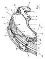
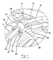
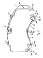
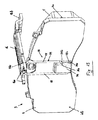
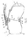
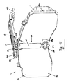
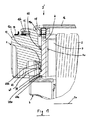
図1,1aおよび2は、戻し装置を備える本発明に係るディスクブレーキ10の実施例を上方から様々な視角で見た斜視図である。
1, 1a and 2 are perspective views of an embodiment of a
ブレーキディスク回転軸線2aを有するブレーキディスク2には、ブレーキキャリパ1が跨がっている。ブレーキキャリパ1は、ブレーキディスク2に関して軸方向で、ブレーキディスク回転軸線2a方向で移動自在にブレーキ支持体6に取着されている。このためにブレーキキャリパ1は、ブレーキ支持体6に結合されたガイドバー(図示せず)に支持されている。ブレーキ支持体6は、車両に不動に保持されている。
A brake caliper 1 straddles the
図1は、ブレーキ支持体6を、ブレーキディスク2、ブレーキディスク2のブレーキディスク回転軸線2aおよびブレーキパッド3,3’とともに、作動側から見た図で示している。ブレーキ支持体6の取り付け側6aは、対応する車両の不動の構成部材(図示せず)に結合されている。このためにブレーキ支持体6は、ブレーキキャリパ1を支持するガイドバー(図示せず)用の受け部6bと、作動側の弓形のブリッジ結合部6cとを有している。
FIG. 1 shows the
加えて図1は、4つのばね腕20と、1つの保持アーチ21とを有する拡開装置8を示している。拡開装置8は、本実施の形態では、2つの同一のばね腕20からなり、両ばね腕20は、中央領域で互いに結合されているとともに、保持アーチ21にも結合されている。保持アーチ21は、ヨーク21aを介してブレーキ支持体6に、具体的にはブレーキ支持体凸部25に取り付けられている。保持アーチ21を軸方向で留めるために、ヨーク21aには、リテーニング手段13が、保持アーチ21のそれぞれの端部をリテーニング手段13間に挟持するように設けられている。
In addition, FIG. 1 shows a spreading
このとき、ばね腕20は、ライニング支持プレート4の、互いに反対側に位置する2つの端部領域に、具体的には、上側に突出した縁部領域において当接する。ばね腕20の端部は、同様に曲げられており、その結果、ブレーキの作動および解除時、ライニング支持プレート面に沿って問題なく滑動することができる。このとき、作動時に生じたプリロードによって、ブレーキの解除後、ブレーキパッド3,3’を拡開させることができる。
At this time, the
拡開装置8については、下でさらに別の形態との関連で詳しく説明する。
The spreading
ブレーキキャリパ1は、作動部11、キャリパ背部12および2つのストラット13を有する。作動部11は、片面でもってブレーキディスク2の平面に対して平行に、ブレーキディスク2の一方の側で延びている。ブレーキディスク2の他方の側には、同じくブレーキディスク2に対して平行に延びるように、キャリパ背部12が配置されている。キャリパ背部12は、作動部11に、それぞれの端部においてそれぞれ1つのストラット13により結合されている。このときストラット13は、作動部11およびキャリパ背部12に対して略直角に延びている。
The brake caliper 1 has an operating
作動部11は、内室を有し、内室内には、ディスクブレーキ10の作動装置(図示せず)が配置されている。内室の開口は、ブレーキディスク2に向かっており、ベースシート19と称するプレートにより閉鎖されている(図1a参照)。
The operating
作動部11と、キャリパ背部12と、ストラット13とは、この配置では、ブレーキディスク2の上方に広がる中央の開口9をその間に画定している。開口9は、仮想の長手方向中央線、つまり、ブレーキディスク2の平面内にあり、両ストラット13の仮想の中央を結んだ長手方向中央線を有する。さらに開口9は、作動部11の仮想の中央と、キャリパ背部12の仮想の中央とを結んだ別の仮想の横方向中央線を有する。この長手方向中央線と、この横方向中央線とは、仮想の中心点で交差する。この仮想の中心点は、本明細書では、開口9のバーチャルな中心と称する。
In this arrangement, the actuating
ブレーキ支持体6内には、ブレーキパッド3,3’が、それぞれ2つのブレーキ支持体凸部25間の「パッドチャネル」内に配置されており、ブレーキパッド3,3’の下面領域でそれぞれのパッドチャネル底6dに載置されている。このことは、図1に明瞭に看取可能である。ブレーキパッド3,3’は、制動時、両側からブレーキディスク2に圧着可能である。その際、各ブレーキパッド3,3’は、ライニング支持プレート4を有し、さらに、ライニング支持プレート4の、ブレーキディスク2側の面に取り付けられた摩擦ライニング5を、ライニング側4a(図5参照)に有する。摩擦ライニング5は、機能中、つまり制動時、ブレーキディスク2に押し付けられている。ライニング支持プレート4の他方の側は、以下では、プレッシャ側4b(図5も参照)という。
In the
ブレーキパッド3,3’には、中央の開口9を通して交換および保守のためにアクセス可能である。ブレーキパッド3,3’は、この中央の開口9を通して、それぞれの対応するパッドチャネルに装入され、再びパッドチャネルから取り出されることができる。パッドチャネルは、それぞれ、側方でブレーキ支持体凸部25により画定されており、ブレーキパッド3,3’は、それぞれ、ブレーキパッド下面の一部領域でパッドチャネル底6d(図11参照)に立設されている。
The
ブレーキディスク回転軸線2a回りの回転矢印は、ディスクブレーキ10が配設された車両の前進走行時の主回転方向を略示している。ブレーキディスク2の主回転方向に関して、ディスクブレーキ10には、回入側ESが規定され、その反対側に回出側ASが規定されている。これに応じて、ブレーキ支持体凸部25について、回入側ESにあるものは、回入側のブレーキ支持体凸部25といい、回出側ASにあるものは、回出側のブレーキ支持体凸部25という。
A rotation arrow around the brake disc rotation axis 2a schematically indicates a main rotation direction during forward traveling of the vehicle on which the
ブレーキパッド3,3’の上方には、開口9の横方向あるいはブレーキディスク回転軸線2a方向で作動部11とキャリパ背部12との間にパッド保持ヨーク16が配置されている。パッド保持ヨーク16の作動側の保持端部16aは、ブレーキキャリパ1の作動部11に設けられた保持部分14に取り付けられており、パッド保持ヨーク16の反対側の背部側の保持端部16bは、キャリパ背部12の保持部分15に固定されている。このために、パッド保持ヨーク16の背部側の保持端部16bは、背部側のブレーキパッド3’に取着されたクリップ要素18のクリップ18aによって取り付けが行われており、詳細な説明はしないリテーニング要素17によって、この取り付けが解けないよう留められている。
Above the
パッド保持ヨーク16は、本実施の形態では、パッド保持ヨーク16の下面の一部領域で両ブレーキパッド3,3’のクリップ要素18を押圧し、これによりブレーキパッド3,3’のパッド保持ばね7も押圧する。これによりブレーキパッド3,3’は、そのパッドチャネル内に保持される。パッド保持ばね7は、それぞれ、ライニング支持プレート4に設けられた突出部31に保持されている。
In the present embodiment, the
制動は、ブレーキキャリパ1の作動部11内の収容室に配置された作動装置を用いて、例えばブレーキレバーにより実施される。ブレーキレバーは、ブレーキキャリパ1のドーム内に位置決めされている。対応するブレーキパッド3は、作用側または作動側のブレーキパッドともいい、制動時に最初にブレーキディスク2と接触する。以後の経過中、発生する反力により、ブレーキキャリパ1は、反作用側のブレーキパッド3’を伴って反対方向に移動し、反作用側のブレーキパッド3’は、同様にブレーキディスク2に摩擦接触する。反作用側のブレーキパッド3’は、背部側のブレーキパッドともいい、以下では、符号3’により作動側のブレーキパッド3と区別する。
The braking is performed by, for example, a brake lever using an operating device arranged in a storage chamber in the operating
ブレーキの解除後、対向する両ブレーキパッド3,3’は、戻し装置により、ブレーキディスク2がブレーキパッド3,3’に対して自由に回転するようにブレーキディスク2から解離される。
After releasing the brake, the opposing
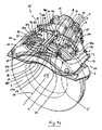
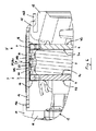
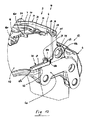
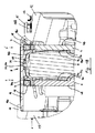
図3は、図1に示したディスクブレーキの実施例の戻し装置の第1の機能群の斜視図である。図4〜6は、図1〜3に示した第1の機能群の詳細を示す様々な概略部分図である。 FIG. 3 is a perspective view of a first functional group of the return device of the embodiment of the disc brake shown in FIG. 4 to 6 are various schematic partial views showing details of the first functional group shown in FIGS.
戻し装置は、ここでは、2つの機能群からなる。第1の機能群は、少なくとも1つの拡開装置8を有し、第2の機能群は、少なくとも1つの戻し要素を有する。両機能群は、本実施の形態では、ともに存在し、補助し合う。しかし、両機能群の一方のみが使用されてもよい。
The return device here consists of two functional groups. The first functional group has at least one spreading
第1の機能群は、拡開装置8でもって、対向するブレーキパッド3,3’のライニング支持プレート4の上側の領域において作動方向とは反対方向に同様に作用する。第2の機能群は、単数または複数の戻し要素により、対向するブレーキパッド3,3’のライニング支持プレート4の中央の領域または/および下側の領域において、それぞれ、押圧力または/および引っ張り力をブレーキパッド3,3’に対して、同じく作動方向とは反対方向に及ぼす。こうしてブレーキパッド3,3’には、ブレーキパッド3,3’の上側の領域でも、ブレーキパッド3,3’の中央の領域または/および下側の領域でも、戻し装置によって同時に戻し力が加えられる。
The first functional group acts similarly in the direction opposite to the operating direction in the region above the lining
拡開装置8は、1つの保持アーチ21と、2つの拡開要素とを有し、両拡開要素は、ばね腕20の2つの同一のペアである。保持アーチ21は、不動であり、ばね腕20のペア用の保持手段を形成している。
The spreading
保持アーチ21は、本実施の形態では、線材としてC字形に形成されており、例えば円形の横断面を有して構成されている。
In this embodiment, the holding
保持アーチ21は、中央部分26aを開口9の中央の領域に有する。中央部分26aは、ブレーキディスク2の厚さに関してブレーキディスク2の中央に配置されている。中央部分26aの各側には、中央脚片26が接続しており、中央脚片26は、中央部分26aと同様、それぞれ弧状にブレーキディスク2の周方向でブレーキディスク2に対して同軸に延びている。而して保持アーチ21は、開口9の中央から両側に、それぞれ作動側のブレーキパッド3のパッドチャネルのブレーキ支持体凸部25まで延在している。
The holding
中央脚片26の各端部には、端部脚片27が設けられている。端部脚片27は、中央脚片26に対して90°曲げられており、それぞれのブレーキ支持体凸部25に向かって延びている。而して各端部脚片27は、ブレーキディスク軸線2aに対して平行に延び、その後、下向きに約90°曲げられてそれぞれ1つの取り付け部分27aに移行している。各取り付け部分27aは、各ブレーキ支持体凸部25の孔25a内に取り付けられており、これにより、保持アーチ21を拡開装置8共々、ブレーキ支持体6内に保持している。
An
その際、不動の部分を形成するブレーキ支持体6に保持アーチ21が取り付けられ、ブレーキキャリパ1が、ブレーキ支持体6に対して移動自在に支持されている点において、保持アーチ21は、ブレーキキャリパ1用のセンタリング装置を形成している。その結果、ブレーキの解除および拡開装置8の拡開後、すなわちブレーキパッド3を押し離した後、ブレーキキャリパ1は、センタリング位置に案内される。
At that time, the holding
ばね腕20の各ペアの両ばね腕20は、保持アーチ21の中央部分26aに関して鏡面対称に形成されている。
Both
ばね腕20のペアは、開口9の横方向で対向するように配置され、ばね腕20の、開口9の中央寄りの内側の端部が、保持アーチ21に取り付けられ、外側の自由端部が、ブレーキパッド3,3’のライニング支持プレート4と協働するようになっている。その際、ばね腕20の一方のペアは、開口9の中心点の右側に配置され、ばね腕20の他方のペアは、開口9の中心点の左側に配置されている。
The pair of
図4は、ばね腕20の一方のペアの内側の端部を保持アーチ21に取着したところを拡大して示した図である。図5は、ばね腕20の外側の自由端部の、対応するライニング支持プレート4と協働する加圧部分22aを拡大して示した図である。図6は、ブレーキディスク回転軸線2aの一鉛直平面内でディスクブレーキ10を断面した概略部分断面図である。
FIG. 4 is an enlarged view of the inner end of one pair of
ばね腕20の1つのペアの両ばね腕20の一方についての説明は、図3および4に明瞭に看取可能であるように、当該ペアの他方のばね腕20についても鏡面対称的に当てはまる。
The description of one of the
各ばね腕20は、内側の端部と、外側の端部とを有する複数回曲げられた本体を有する。ばね腕20の1つのペアの両ばね腕20の内側の端部は、互いに平行に延びる結合部分20bとして形成されており、結合部分20bは、1つの共通のフード状結合部20cにより結合されている。フード状結合部20cにより、保持アーチ21へのばね腕20のペアの取り付けがなされている。その際、保持アーチ21の中間部分26aは、拡開装置8が組み込まれた状態にあっては、平行に延びる両結合部分20b間を延びている。各ばね腕20の外側の自由端部は、加圧部分20aが設けられた端部部分20dを有する。加圧部分20aは、ライニング支持プレート4と協働する長穴22を有する。これについては下でさらに詳しく説明する。
Each
フード状結合部20cは、両側でそれぞれ、各ばね腕20のそれぞれ1つの延長部を形成する結合部分20bに結合されており、一種のスリーブ形状をなして保持アーチ21の中央部分26aを取り巻くように曲げられている。こうして各フード状結合部20cは、ばね腕20のペアの両ばね腕20とともに保持アーチ21の中央部分26a上に回動可能に支持されている。
The hood-
各フード状結合部20cは、下向きにブレーキディスク2に向いた受容開口を保持アーチ21の中央部分26aの長手方向で有し、受容開口は、保持アーチ21の中央部分26aの外側輪郭に対応している。ペア状にそれぞれ1つのフード状結合部20cに結合されたばね腕20は、中央部分26aがフード状結合部20cの受容開口内に受容されているように、それぞれのフード状結合部20cでもって保持アーチ21の中央部分26aに上から載設されている。
Each hood-
さらに拡開装置8は、留め具を有し、留め具は、本明細書では長手方向結合部23と称する中央ウェブを有する。さらに留め具は、リテーニング要素26cとしての4つの折り返し舌片と、ばね腕20をライニング支持プレート4に押さえ付ける働きをする拡幅部26bとしての4つの押さえとを有する。
Further, the spreading
拡幅部26bは、それぞれ両側で、保持アーチ21の中央部分26aが中央脚片26へと移行するところでばね腕20の結合部分20bに載置されている。こうして拡幅部26bは、フード状結合部20cが中央部分26aから持ち上がってしまうことを防止している。同時に拡幅部26bは、中央部分26aの長手方向軸線方向でそれぞれ開口9の中央から外方に、隣接するストラット13へと向かう、ばね腕20のそれぞれのペアのフード状結合部20c用の軸方向のストッパを形成している(図1、2および4参照)。
The widened
ばね腕20のそれぞれ2つの結合部分20bは、その自由端部でもって開口9の中央に向かっており、それぞれ、その端部領域においてリテーニング要素26cと結合されている。リテーニング要素26cは、それぞれ2つの折り返し舌片からなり、折り返し舌片は、それぞれ一方の端部でもって、結合部分20bのそれぞれ1つの端部領域に設けられた溝26d内に固定されている。こうしてリテーニング要素26cは、それぞれのフード状結合部20cが中央部分26aから解離しないようにする別のリテーニング手段を形成している。
Each of the two connecting portions 20b of the
拡開要素の張設は、留め具のリテーニング要素26cとしての折り返し舌片により保証され、折り返し舌片は、組み立て時に折り返され、溝26d内に係合させられる。而して拡開要素は、中央に向かって滑動したり、ライニング支持プレート4に対して傾動したりしないように留められている。
The tensioning of the spreading element is ensured by a folded tongue as a retaining
留め具の中央ウェブ(長手方向結合部23)がさらに縦通しているため、留め具も、もはや軸方向で保持アーチ21上を滑動し得ない。それゆえ、溶接シームその他の固定手段は省略可能である。付加的に留め具は、スペーサとしても用いられる。
Because the central web of the fastener (longitudinal joint 23) is further threaded, the fastener can no longer slide on the retaining
これにより拡開装置は、特に柔軟性および適合性を有する。 Thereby, the spreading device is particularly flexible and adaptable.
各ばね腕20の本体は、複数回曲げられている。その際、本体は、ブレーキキャリパ1の対応するストラット13へと向かう結合部分20bの端部を起点に、まず、保持アーチ21から離間するようにS字形の弧をなして延びており、このS字形の弧の、ストラット側の端部は、保持アーチ21に対して所定の間隔を置いて存在している。この所定の間隔は、保持アーチに対する結合部分20bの間隔の例えば2.5倍の大きさである。S字形の弧のこの端部は、別のS字形の弧に移行する。この別のS字形の弧の自由端部は、端部部分20dであり、保持アーチ21から今や、保持アーチ21に対する第1のS字形の弧の端部の間隔の例えば2.5倍の間隔を置いている。
The main body of each
端部部分20dには、加圧部分20aが、弧状に下向きに延びる結合部分を介して設けられている。その際、加圧部分20aは、ブレーキディスク2に対する接線方向平面内に位置している。
The
加圧部分20aは、加圧部分20aのそれぞれの長手方向で長穴22を有して形成されており、長穴22は、拡開装置8のばね腕20用のガイド部分として用いられる。ただし、長穴22の中央長手方向軸線は、対応するライニング支持プレート4の長手方向軸線に関して、例えば0°より大きく、45°より小さい範囲内にある角度をなして延びている。その際、1つの共通のライニング支持プレート4に属するこれらの加圧部分20aの長穴22の中央長手方向軸線は、1つの仮想の交点で交差する。この仮想の交点は、ライニング支持プレート4の、摩擦ライニング5が配置されている側に位置する。
The pressurizing
加圧部分20aは、その長穴22でもって、ディスクブレーキ10が組み立てられた状態で、それぞれ1つの棒体24と、図5に明瞭に看取可能であるように協働する。ライニング支持プレート4の各端部において、棒体24は、堅固にライニング支持プレート4に結合、例えば孔内に挿入されている。その際、棒体24の、ライニング支持プレート4から突出した端部は、拡開装置8のばね腕20のそれぞれの加圧部分20aの対応する長穴22を貫いて延在している。これらの棒体24の中心軸線は、互いに平行に、かつブレーキディスク回転軸線2aに対して垂直に延びている。長穴22は、拡開装置8のばね腕20と、ブレーキディスク回転軸線2a方向で移動するブレーキパッド3との間の相対運動を可能にする。ばね腕20のばね力は、既に上述したように、制動後にブレーキパッド3をブレーキディスク2から解離し、戻すことを可能にする。
The pressurizing
その際、取り付け部分20aは、それぞれ載置面20eでもってそれぞれのライニング支持プレート4の載置面4cに載置される。ライニング支持プレート4の載置面4cは、ブレーキディスク2に対して接線方向で延び、ブレーキパッド3毎に一平面内に位置する。
At that time, the
ばね腕20と、ばね腕20の加圧部分20aと、フード状結合部20cを有するばね腕20の結合部分20bとは、例えば一体に打ち抜き曲げ部材として帯状ばね鋼から形成されている。而して拡開要素、すなわちばね腕20は、例えば幾何学的に柔軟な低コストの金属薄板から形成可能である。
The
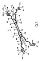
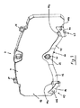
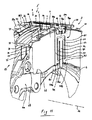
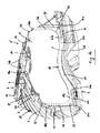
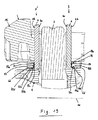
図7ないし8は、図1に示したディスクブレーキの実施例の戻し装置の第2の機能群の斜視図である。 7 to 8 are perspective views of a second functional group of the return device of the embodiment of the disc brake shown in FIG.
図7は、戻し要素40を有する作動側あるいは内側のブレーキパッド3のライニング支持プレート4のプレッシャ側4bの斜視図である。
7 is a perspective view of the
ライニング支持プレート4のプレッシャ側4bは、ライニング支持プレート4の、摩擦ライニング5を担持せず、作動装置またはキャリパ背部12と接触する側である。
The
戻し要素40は、制動プロセス後に作動側のブレーキパッド3をブレーキディスク2から戻す補助をする。その際、ばね腕20の上面における単数または複数の作用点に加えて、戻し要素40は、一部分でもってライニング支持プレート4に下側の領域で作用し、別の一部分でもって、戻し要素40に対して相対的に不動の部分、例えばブレーキキャリパ1または/およびブレーキ支持体6に結合されている。
The
このために戻し要素40は、図7に示した形態では、一部分でもってライニング支持プレート4のプレッシャ側4bにおける下側の領域で保持スタッド32に取り付けられている。保持スタッド32は、当然のことながら、例えばねじ、ボルト等、これとは異なる形態で形成されていてもよい。加えて戻し要素40は、別の一部分でもってブレーキキャリパ1の作動部11のベースプレート19(図1も参照)の下側の領域に取着されている。
For this purpose, in the form shown in FIG. 7, the
これに加え、図8は、ベースプレート19と、透視的に描いた、戻し要素40が係合したライニング支持プレート4との概略斜視図である。
In addition, FIG. 8 is a schematic perspective view of the base plate 19 and the
戻し要素40は、本実施の形態では、1つの中央部分41と、2つのばね腕42と、2つの取り付け部分43とを有するばね要素であり、取り付け部分43は、脚片44aを有するそれぞれ1つのU字形の舌片44を有する。中央部分41と、ばね腕42とは、例えばフラットな帯状ばね鋼から製造されており、取り付け部分43は、一般的な鋼薄板であってもよい。
In the present embodiment, the
中央部分41は、中央で保持スタッド32にクランプ結合/つめ結合を介して結合されている。中央部分41は、各側で対称にそれぞれのばね腕42に移行している。各ばね腕42は、中央部分41から左右にライニング支持プレート4の下側の領域においてこれに沿うように延在し、ライニング支持プレート4の輪郭に合わせて成形されている。各ばね腕42の端部は、それぞれ、取り付け部分43に結合されている。各取り付け部分43は、舌片44のU字形の弧および脚片44aが、互いに一直線に並び、かつブレーキディスク回転軸線2aに対して接線方向で位置するように成形されている。取り付け部分43の、それぞれベースプレート19に向かう脚片は、外向きに舌片44として延び、ベースプレート19のねじによりベースプレート19に固定するためのそれぞれ1つの取り付け孔44bを有するように拡幅している。ねじは、ベースプレート19の既存の取り付けねじであってもよい。
Central portion 41 is centrally coupled to retaining
制動プロセス後、ブレーキパッド3,3’は、一方では、拡開装置8のばね腕20により再び押し離され、而してブレーキディスク2から戻される。同時に、既にプリロードが与えられた状態で組み込まれていてもよい戻し要素40は、制動プロセス時、戻し要素40の取り付け部分43がベースプレート19に不動に固定されていることに基づいて付勢され、制動プロセス後、付加的にブレーキパッド3を、こうして蓄勢された引っ張り力の働きによりブレーキディスク2から引き戻すことができる。
After the braking process, the
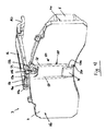
図9〜17は、戻し装置の第2の機能群の変化態様の斜視図である。 9-17 is a perspective view of the change aspect of the 2nd function group of a return apparatus.
図9は、図8に示した戻し装置の第2の機能群の第1の変化態様を示している。取り付け部分43は、図8に示した形態の取り付け部分43と同一である。図8に示した形態とは異なり、本第1の変化態様の戻し要素40は、ばね線材から形成されている。ばね線材は、2つのばね腕45を有し、両ばね腕45は、中央部分45aにより結合されている。ばね腕の自由端部は、端部部分45bとしてそれぞれの取り付け部分43に堅固に結合、例えば溶接されている。中央部分45aは、本変化態様では、ばね線材の構成部分であり、ライニング支持プレート4の下面に設けられたホルダ33に取り付けられている。
FIG. 9 shows a first variation of the second function group of the return device shown in FIG. The
ホルダ33は、本変化態様では、ヘッドプレートを有するボルトとして構成されており、ヘッドプレートの直径は、ボルト本体より大きい。ホルダ33は、ライニング支持プレート4の下面に設けられた凹所33a内に配置されている。その際、中央部分45aは、凹所33a内において凹所33aの底とボルトのヘッドプレートとの間のボルトの領域に巻き掛けられている。
In this variation, the
戻し要素40の機能は、図7〜8に示した形態との関連で説明したとおりである。
The function of the
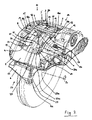
図10は、第2の機能群の第2の変化態様を示しており、さらに、対応するパッドチャネル内に組み込まれた作動側のブレーキパッド3の右半部をブレーキ支持体6とともに示している。ブレーキパッド3は、作動側の保持端部16aが見て取れるパッド保持ヨーク16により、突出部31に保持されたパッド保持ばね7を介してパッドチャネル内に押し込まれている。ブレーキ支持体6は、図10にその取り付け側6aとともに示してあり、取り付け側6aには、符号を付すことはしないが、対応する車両の不動の部分への取り付けに用いられる複数の取り付け穴が作り込まれている。これに加え、右側の、この場合は回出側(図1参照)のブレーキ支持体凸部25も、ブレーキ支持体凸部25の下に配置された受け部6bとともに図示されている。受け部6bは、ブレーキキャリパ1の長手方向支持装置の支持バーを受ける。
FIG. 10 shows a second variation of the second functional group, and further shows the right half of the working
第2の変化態様において、第2の機能群は、2つの戻し要素46を有し、図10には、両戻し要素46のうち、ライニング支持プレート4の右下側に設けられた右側の戻し要素46のみ示してある。本第2の変化態様の第2の戻し要素46は、ライニング支持プレート4の、図10には示さないが、容易に想像可能な左下側に、右側の戻し要素46に対して鏡面対称に配置され、相応に構成されている。
In the second variation mode, the second functional group includes two
戻し要素46は、締結端部47aと結合部とを有する第1のばね腕47と、結合部48aを有する第2のばね腕48と、開口49aを有する取り付け部分49とを有する。
The
第1のばね腕47は、その締結端部47aでもってホルダ34内に差し込まれ、例えばクランプ作用/溝作用等によりホルダ34に取り付けられている。ホルダ34は、本変化態様では、ライニング支持プレート4のプレッシャ側4bの右下の角隅に突出しており、例えばライニング支持プレート4の製造時に一体に鋳造されていてもよい。
The
第1のばね腕47は、ライニング支持プレート4のプレッシャ側4bの手前を下側の領域にてホルダ34から左方にライニング支持プレート4の中央に向かって、ライニング支持プレート4の長さの約3分の1に相当する長さで延在している。その後、第1のばね腕47は、結合部47bに移行し、結合部47bは、約180°外向きに、すなわち作動部11に向かって曲げられている。
The
而るに結合部47b自体は、第2のばね腕48に移行し、第2のばね腕48は、第1のばね腕47とは反対方向に第1のばね腕47に対して平行にホルダ34を越えるところまで延在している。結合部48aは、ライニング支持プレート4に向かう一種の屈曲部として形成されており、取り付け部分49に結合されている。
Thus, the coupling portion 47 b itself moves to the second spring arm 48, and the second spring arm 48 is a holder parallel to the
取り付け部分49の大きな開口49aは、ブレーキ支持体6の受け部6bの開口の手前に、この開口に対して同軸に位置する。これにより、ブレーキ支持体6を取り付けた後は、取り付け部分49も、取り付け側6aと、対応する車両の不動の部分との間に不動に固定されている。
The large opening 49 a of the
さらに図10は、保持アーチ21の一変化態様を示している。保持アーチ21の本変化態様では、端部脚片27の、互いに向かい合った側には、それぞれ1つの端部部分28に、舌片29が設けられている。舌片29には、スタッド30が保持されている。スタッド30は、ブレーキ支持体凸部25の、符号は付さない孔内に係合している。舌片29は、ブレーキ支持体凸部25の平らな端面に載置されている。スタッド30は、リベットとして形成され、ブレーキ支持体凸部25の孔内に差し込まれていてもよい。スタッド30は、ブレーキ支持体凸部25に一体成形されていても、別体の構成部材として既に前もって堅固に挿入されていてもよい。
Further, FIG. 10 shows a variation of the holding
両戻し要素46は、例えば打ち抜き曲げ部材としてフラットなばね鋼材料から製造されていてもよい。
Both return
両戻し要素46の機能は、上で既に説明したとおりであり、戻し要素46を固定する不動の部分は、この場合、ブレーキ支持体6であり、引っ張り力は、ライニング支持プレート4の2つの角隅点にホルダ34を通して導入される。
The function of both return
図11は、中央の戻し要素50を有する第2の機能群の第3の変化態様を示している。
FIG. 11 shows a third variant of the second functional group with a
戻し要素50は、鉛直方向で作動側のライニング支持プレート4のプレッシャ側4bの中央に配置され、ライニング支持プレート4の上面および下面に取り付けられており、中央の戻し要素50の一方の端部の不動の固定部は、ブレーキ支持体6の作動側のブリッジ結合部6cの中央に形成されている。
The
中央の戻し要素50は、互いに平行に配置される2つの側方の長手方向部材51を有し、長手方向部材51の上側の端部は、クリップであるクランプ部分51aとしてライニング支持プレート4の上面をクリップ要素18の左右にて堅固に抱持している。両長手方向部材51の下側の端部には、同様にこのようなクランプ部分51bが設けられており、クランプ部分51bは、クリップとしてライニング支持プレート4の下面を堅固に抱持している。
The
両長手方向部材51は、上側のクランプ部分51aの下方で横方向結合部52により互いに結合されている。長手方向部材51の下側は、下側のクランプ部分51bの上方でそれぞれ1つの横方向結合部53に結合されている。横方向結合部53には、それぞれ1つの別の長手方向部材54が設けられている。両別の長手方向部材54は、それぞれ、外側の長手方向部材51に対して平行に上向きに延在し、両別の長手方向部材54の上側の端部において横方向結合部53の下方で別の横方向結合部55に結合されている。
Both longitudinal members 51 are coupled to each other by a lateral coupling portion 52 below the upper clamp portion 51a. The lower side of the longitudinal member 51 is coupled to one
この別の横方向結合部55の中央には、中央の長手方向部材56が設けられており、中央の長手方向部材56は、両長手方向部材54間を下向きにクランプ部分51bを越えて延在し、固有のクランプ部分56aで終端している。この中央のクランプ部分56aは、ブレーキ支持体6の不動のブリッジ結合部6cの中央に好適な形式で固定、例えばクランプ固定されている。
A central longitudinal member 56 is provided at the center of the other
機能は、上述したとおりである。 The function is as described above.
図12ないし15は、作動側のブレーキパッド3の作動側のライニング支持プレート4のプレッシャ側4bに設けられた中央の戻し要素50の変化態様を、パッド保持ヨーク16とともに示している。
FIGS. 12 to 15 show the variation of the
ライニング支持プレート4への戻し要素50の固定部は、それぞれ、ライニング支持プレート4の下側の領域に配置されており、戻し要素50の不動の固定部は、それぞれ、パッド保持ヨーク16の作動側の保持端部16aに設けられている。戻し要素50の機能は、既に上述したとおりである。
The fixing portions of the
図12に示した戻し要素50は、互いに平行に配置される2つの長手方向部材58を有する線材形のばね体57を有する。両長手方向部材58は、本変化態様では、下側で横方向結合部58aにより互いに結合されており、横方向結合部58aは、中央において、ライニング支持プレート4の下側の領域に設けられた保持アングル35の下に保持されている。長手方向部材58と、横方向結合部58aとは、一体にばね線材から曲げ部材として製造されていてもよい。
The
一方の長手方向部材58、本変化態様では右側の長手方向部材58の上側の端部は、中央に向かって端部部分58bとして約90°曲げられ、パッド保持ヨーク16の作動側の保持端部16aに設けられた保持手段59のホルダ部分59b内に取着されている。他方(左側)の長手方向部材58の上側の端部は、類似の形式で中央に向かって端部部分58cとして約90°曲げられ、保持手段59に取り付けられている。このことは、図12には示していないものの、容易に理解可能である。この場合、曲げられた端部部分58b,58cは、鉛直方向で互いにずらされて配置されている。
One
保持手段59は、本変化態様では、打ち抜き曲げ部材としてクリップ形のホルダ部分59aを有して形成されており、ホルダ部分59aは、パッド保持ヨーク16の保持端部16aの一部領域を抱持している。
In this variation, the holding means 59 is formed to have a clip-shaped
保持アングル35は、その下側で脚片35aを介してライニング支持プレート4のプレッシャ側4bに取り付けられており、本変化態様では、ライニング支持プレート4の鉛直方向の長さの約4分の1にわたって上向きに延在している。その際、横方向結合部58aは、略中央においてライニング支持プレート4のプレッシャ側4bと、保持アングル35の裏面との間に保持されている。
The holding angle 35 is attached to the
図13では、戻し要素50が図12と同様に形成されているが、180°反転されて配置されている。横方向結合部58aは、パッド保持ヨーク16の作動側の保持端部16aの下に取着されている。端部部分58bおよび58cは、ブロック状のホルダ36内に設けられた好適な保持開口36a内に収められ、相対回動不能に固定されている。ホルダ36は、ライニング支持プレート4の製造時に一体に鋳造されていてもよい。
In FIG. 13, the
図14は、単一のばね体60を有する別の戻し要素50を示しており、ばね体60は、下側の端部部分60aでもって保持ヨーク37内の保持開口37a内に差し込まれている。ばね体60の上側の端部は、一巻きのばねの形態で取り付け部分60bとして構成されており、図12との関連で説明したものと類似の保持手段59に取着されている。この取着は、種々様々に行われていてよく、例えば取り付け部分60bは、差し込まれたり、保持手段59に溶接されたりしている。ばね体60には、本変化態様では、比較的大きな半径を有する2つの弧が設けられている。保持ヨーク37は、ライニング支持プレート4のプレッシャ側4bに一体に鋳造されていてもよい。
FIG. 14 shows another
図15は、別の変化態様を示している。本変化態様では、戻し要素50は、ばねプレート61として構成されている。ばねプレート61の幅は、本変化態様では、ブレーキディスク回転軸線2a方向でのライニング支持プレート4の厚さの例えば2倍に等しい。ばねプレート61は、既に上述したのと同様、端部部分61aでもって保持ヨーク38の保持開口内に係合している。ばねプレート61の取り付け部分61bは、パッド保持ヨーク16の作動側の保持端部16aに設けられた既に上述の保持手段59に好適な形式で取着、例えば差し込まれたり、掛着されたり、溶接されたり等、している。
FIG. 15 shows another variation. In this variation, the
拡開装置8の第2の機能群の前述の例は、それぞれ、作動側のブレーキパッド3に関する。拡開装置8の第2の機能群は、当然のことながら、背部側のブレーキパッド3’にも設けられていてよい。
The aforementioned examples of the second functional group of the spreading
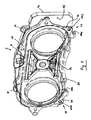
図16および17は、背部側のブレーキパッド3’用の戻し要素の変化態様の例を示している。 FIGS. 16 and 17 show examples of variations of the return element for the brake pad 3 'on the back side.
図16は、ブレーキ支持体6内にブレーキ支持体凸部25間において設けられた対応するパッドチャネル内に収容された背部側のブレーキパッド3’のライニング支持プレート4のプレッシャ側4bの概略斜視図である。これに加え、背部側の保持端部16bを有するパッド保持ヨーク16も図示してあり、保持端部16bには、クリップ18aとリテーニング要素17とが設けられている(詳しい説明は割愛する)。
FIG. 16 is a schematic perspective view of the
戻し要素62は、2つの結合部分63aを有する1つの中央部分63と、それぞれ1つのばね端部64aを有する2つのばね腕64と、2つの別の結合部分65と、それぞれ1つのクリップ端部66aを有する2つの別のばね腕66とを有する。
The return element 62 comprises one central part 63 having two
中央部分63は、ライニング支持プレート4のプレッシャ側4bの下側の縁部領域に配置され、実質的にこの領域と同様に弓形に形成されている。このように丸み付けた領域の各終端に、中央部分63は、両側に結合部分63aを有する。
The central portion 63 is disposed in the lower edge region of the
各結合部分63aには、下側の領域にそれぞれ1つのばね腕64が設けられている。各ばね腕64は、ブレーキディスク2に関して接線方向で、それぞれのブレーキ支持体凸部25の片面を越えるまで延在し、それぞれのばね端部64aは、それぞれのブレーキ支持体凸部25の側面に。
Each
各ばね腕64の上方では、腕65aを有するそれぞれ1つの別の結合部分65が、それぞれの結合部分63aに結合されている。腕65aは、それぞれ、ばね腕64に対して平行にプレッシャ側4bにおいて、対応する結合部分63aからライニング支持プレート4のそれぞれの側縁まで延在し、対応する結合部分65に移行している。
Above each
結合部分65は、ライニング支持プレート4の角隅領域の外形に適合されており、ライニング支持プレート4の中央に向かって対角方向で拡幅され、かつ丸み付けられているとともに、それぞれ、上向きにばね腕66に移行している。
The
各ばね腕66は、ライニング支持プレート4の側方領域に沿ってプレッシャ側4bを、ライニング支持プレート4の、斜めになった上側の側面部分4dまで延在している。ばね腕66の各上側の端部には、1つのクリップ部分66aが設けられており、クリップ部分66aは、それぞれ1つの斜めの側面部分4dに跨がるようにライニング支持プレート4に取り付けられている。
Each
中央部分63は、図示しない単数または複数の例えばクリップ部分により、ライニング支持プレート4に取り付けられていてもよい。
The central portion 63 may be attached to the
こうして戻し要素62は、一方では、ばね腕66のクリップ部分66aにより背部側のブレーキパッド3’のライニング支持プレート4に取着されており、他方では、ばね腕64を介してそのばね端部64aでもってブレーキ支持体凸部25に不動に固定されている。この取り付けは、既に戻し要素62のプリロードを生じさせるようになっていてもよい。
Thus, the return element 62 is on the one hand attached to the
制動プロセス時、戻し要素62は、上述のように付勢され、そして、ライニング支持プレート4に取り付けられていることによって、ライニング支持プレート4に対し、制動プロセス後、背部側のブレーキパッド3’をブレーキディスク2から離間させるように戻す引っ張り力を働かせる。
During the braking process, the return element 62 is biased as described above and is attached to the
図17は、別の戻し要素67を有する背部側あるいは外側のブレーキパッド3’を備えるディスクブレーキの、ブレーキディスク回転軸線2aを通る一平面内の断面図である。 FIG. 17 is a cross-sectional view in a plane through the brake disc rotation axis 2a of a disc brake comprising a back or outer brake pad 3 'with another return element 67. FIG.
戻し要素67は、一種の板ばねとして、ばね端部68a,68bを1つずつ有するばね体68を有して形成されている。一方のばね端部68aは、背部側のライニング支持プレート4の下側の領域でライニング支持プレート4のプレッシャ側4bにおいて保持ヨーク39に撓曲自在に取り付けられている。他方のばね端部68bは、好適な形態では、ブレーキキャリパ1のキャリパ背部12の保持部分12aにつめにより掛止されている。戻し要素67は、1つの戻し要素67が中央に設けられていても、2つの戻し要素67が角隅に、あるいはそれよりも多くの戻し要素67が、ライニング支持プレート4の下側の領域の長さにわたって分配されて設けられているようになっていてもよい。
The return element 67 includes a spring body 68 having one spring end portion 68a and 68b as a kind of leaf spring. One spring end portion 68a is flexibly attached to the holding yoke 39 on the
図18は、戻し要素69を有する拡開装置8の第2の機能群の別の変化態様の断面を概略的に、ブレーキパッド3,3’を有するディスクブレーキの、ブレーキディスク回転軸線2aを通る一平面内の断面図として示している。
FIG. 18 schematically shows a cross section of another variant of the second functional group of the spreading
本変化態様において、戻し要素69は、ヨーク状に、対向する2つのばね腕71,72を有して、例えば板ばねまたは/および線材ばねといったばね形態で形成されている。各ばね腕71,72の上側の端部は、それぞれ結合アーチ70a,70bを介して中央部分70に取着されている。戻し要素69の中央部分70は、拡開装置8の保持アーチ21の中央部分26aに取り付けられており、中央部分26aに例えば巻き掛るように曲げられている。
In this variation, the
各結合アーチ70a,70bの下側の端部から、各ばね腕71,72は、下向きにブレーキディスク回転軸線2aに向かって各ブレーキパッド3の下側の領域まで延在している。各ばね腕71,72は、それぞれ1つの圧接脚片71a,72aを有する自由端部を有し、それぞれ、摩擦ライニング5と、ライニング支持プレート4のライニング側4aとの間の縦長の中間室内に配置されており、圧接脚片71a,72aのそれぞれは、それぞれのライニング支持プレート4と接触している。
From the lower end of each coupling arch 70a, 70b, each
本形態において、戻し要素69のばね腕71,72は、それぞれ、押圧力をブレーキディスク2から離間するブレーキディスク回転軸線2a方向でブレーキパッド3,3’に及ぼし、これにより、ブレーキパッド3には、各制動プロセス後、拡開装置8のばね腕20に加えて、下側の領域で戻し要素69のばね腕71,72により戻しのために力が加えられる。
In this embodiment, the
図19は、ガイド要素73を備える図1に示した本発明に係るディスクブレーキ10の概略部分断面図である。
FIG. 19 is a schematic partial sectional view of the
各ガイド要素73は、取り付け部分73aと、取り付け部分73aに取り付けられたガイド部分73bとを有する。取り付け部分73aは、一種の舌片として形成されており、その下側において、まず、ガイド部分73bの、取り付け部分73aの平面から曲げられた腕73cに移行する。ここでは、腕73cは、約45°起曲されている。下向きに曲げられた腕73cの自由端部には、端部部分73dが設けられており、端部部分73dは、腕73cの平面から約90°腕73cと同じ曲げ方向で起曲されており、こうして載置部分73eが形成されている。
Each
ガイド要素73は、ブレーキパッド3,3’の各ライニング支持プレート4の下側の領域に、ガイド要素73の載置部分73eがそれぞれのパッドチャネル底6d(図11も参照)に載置されるように取着されている。その際、取り付け部分73aのそれぞれは、それぞれのライニング支持プレート4のプレッシャ側4bに、取り付け要素74、例えばリベットにより取り付けられている。各ライニング支持プレート4に1つのガイド要素73が中央に配置されていても、複数のガイド要素73がライニング支持プレート4の長さにわたって分配配置されていてもよい。
The
ガイド要素73は、パッドチャネル底6d上へのそれぞれのライニング支持プレート4の載置面をブレーキディスク回転軸線2a方向で拡大する。ここでガイド要素73は、対応するブレーキパッド3,3’に対して力を及ぼすものではなく、既に上述したように、制動プロセス後、例えば拡開装置8のばね腕20によりライニング支持プレート4の上側に作用する力によってブレーキパッド3,3’を戻すときに、ブレーキパッド3,3’が傾倒してしまわないように、ブレーキパッド3,3’にそれぞれ1つの所定の優先方向を与えるものである。
The
本発明は、上述の実施例に限定されるものではない。本発明は、添付の特許請求の範囲内で変更可能である。 The present invention is not limited to the embodiments described above. The invention can be modified within the scope of the appended claims.
1 ブレーキキャリパ
2 ブレーキディスク
2a ブレーキディスク回転軸線
3,3’ ブレーキパッド
4 ライニング支持プレート
4a ライニング側
4b プレッシャ側
4c 載置面
4d,e 側面部分
5 摩擦ライニング
6 ブレーキ支持体
6a 取り付け側
6b 受け部
6c ブリッジ結合部
6d パッドチャネル底
7 パッド保持ばね
8 拡開装置
9 開口
10 ディスクブレーキ
11 作動部
12 キャリパ背部
12a 保持部分
13 ストラット
14,15 保持部分
16 パッド保持ヨーク
16a,16b 保持端部
17 リテーニング要素
18 クリップ要素
18a クリップ
19 ベースシート
20 ばね腕
20a 加圧部分
20b 結合部分
20c フード状結合部
20d 端部部分
20e 載置面
21 保持アーチ
21a ヨーク
21b リテーニング手段
22 長穴
23 長手方向結合部
24 棒体
25 ブレーキ支持体凸部
25a 孔
26 中央脚片
26a 中央部分
26b 拡幅部
26c リテーニング要素
26d 溝
27 端部脚片
27a 取り付け部分
28 端部部分
29 舌片
30 スタッド
31 突出部
32 保持スタッド
33 ホルダ
33a 凹所
34 ホルダ
35 保持アングル
35a 脚片
36 ホルダ
36a 保持開口
37,38,39 保持ヨーク
37a,38a,39a 保持開口
40 戻し要素
41 中央部分
42 ばね腕
43 取り付け部分
44 舌片
44a 取り付け穴
45 ばね腕
45a 中央部分
45b 端部部分
46 戻し要素
47 ばね腕
47a 締結端部
47b 結合部
48 ばね腕
48a 結合部
49 取り付け部分
49a 開口
50 戻し要素
51,54,56 長手方向部材
51a,51b,56a クランプ部分
52,53,55 横方向結合部
57 ばね体
58 長手方向部材
58a 横方向結合部
58b,58c 端部部分
59 保持手段
59a ホルダ部分
59b ホルダ舌片
60 ばね体
60a 端部部分
60b 取り付け部分
61 ばねプレート
61a 端部部分
61b 取り付け部分
62 戻し要素
63 中央部分
63a 結合部分
64 ばね腕
64a ばね端部
65 結合部分
65a 腕
66 ばね腕
66a クリップ端部
67 戻し要素
68 ばね体
68a 締結端部
68b つめ端部
69 戻し要素
70 中央部分
70a,70b 結合アーチ
71,72 ばね腕
71a,72a 圧接脚片
73 ガイド要素
73a 取り付け部分
73b ガイド部分
73c 腕
73d 端部部分
73e 載置部分
74 取り付け要素
AS 回出側
ES 回入側
DESCRIPTION OF SYMBOLS 1 Brake caliper 2 Brake disc 2a Brake disc rotational axis 3, 3 'Brake pad 4 Lining support plate 4a Lining side 4b Pressure side 4c Mounting surface 4d, e Side surface part 5 Friction lining 6 Brake support body 6a Mounting side 6b Receiving part 6c Bridge coupling portion 6d Pad channel bottom 7 Pad holding spring 8 Expanding device 9 Opening 10 Disc brake 11 Actuating portion 12 Caliper back portion 12a Holding portion 13 Struts 14, 15 Holding portion 16 Pad holding yokes 16a, 16b Holding end portion 17 Retaining element 18 Clip element 18a Clip 19 Base sheet 20 Spring arm 20a Pressure part 20b Joint part 20c Hood-like joint part 20d End part 20e Placement surface 21 Holding arch 21a Yoke 21b Retainer 22 Long hole 23 Longitudinal coupling part 24 Rod body 25 Brake support convex part 25a Hole 26 Central leg piece 26a Central part 26b Widening part 26c Retaining element 26d Groove 27 End leg piece 27a Attachment part 28 End part 29 Tongue Piece 30 Stud 31 Protruding portion 32 Holding stud 33 Holder 33a Recess 34 Holder 35 Holding angle 35a Leg piece 36 Holder 36a Holding opening 37, 38, 39 Holding yoke 37a, 38a, 39a Holding opening 40 Return element 41 Central portion 42 Spring arm 43 attachment part 44 tongue piece 44a attachment hole 45 spring arm 45a central part 45b end part 46 return element 47 spring arm 47a fastening end part 47b coupling part 48 spring arm 48a coupling part 49 attachment part 49a opening 50 return element 51, 54, 56 Longitudinal Direction member 51a, 51b, 56a Clamping part 52, 53, 55 Lateral coupling part 57 Spring body 58 Longitudinal member 58a Lateral coupling part 58b, 58c End part 59 Holding means 59a Holder part 59b Holder tongue piece 60 Spring body 60a End portion 60b Attachment portion 61 Spring plate 61a End portion 61b Attachment portion 62 Return element 63 Center portion 63a Connection portion 64 Spring arm 64a Spring end portion 65 Connection portion 65a Arm 66 Spring arm 66a Clip end portion 67 Return element 68 Spring body 68a Fastening end portion 68b Pawl end portion 69 Return element 70 Center portion 70a, 70b Joint arch 71, 72 Spring arm 71a, 72a Pressure contact leg piece 73 Guide element 73a Mounting portion 73b Guide portion 73c Arm 73d End portion 73e Mounting portion 74 Installation required AS run-out side ES times inlet side
Claims (51)
ブレーキディスク(2)に跨がる、摺動キャリパとして形成されるブレーキキャリパ(1)であって、不動のブレーキ支持体(6)に取り付けられており、中央の開口(9)を前記ブレーキディスク(2)の上方に有するブレーキキャリパ(1)と、
前記ブレーキキャリパ(1)内に配置された2つの、互いに反対方向に可動なブレーキパッド(3,3’)であって、それぞれ、ライニング支持プレート(4)と、前記ライニング支持プレート(4)に取り付けられた摩擦ライニング(5)とを有し、前記ブレーキパッド(3,3’)のうちの一方の作用側あるいは作動側のブレーキパッド(3)は、作動装置により少なくとも1つのブレーキピストンを介して前記ブレーキディスク(2)に圧着可能であるブレーキパッド(3,3’)と、
前記ブレーキキャリパ(1)を制動に起因する前記ブレーキキャリパ(1)の移動および前記ブレーキの解除後に戻すことが可能な少なくとも1つの戻し装置であって、対向する前記ブレーキパッド(3)に作用する、それぞれの作動方向とは反対方向に同様に作用する拡開装置(8)を有し、前記拡開装置(8)は、それぞれの前記ライニング支持プレート(4)に作用するばね式の拡開要素を有する戻し装置と、
を備えるディスクブレーキ(10)において、
前記拡開装置(8)は、前記中央の開口(9)内に配置されており、前記拡開要素は、前記摩擦ライニング(5)外で、前記ブレーキパッド(3)の、中央に関して互いに間隔を置いて配置された少なくとも2つの当接領域に直接的または間接的に作用し、前記当接領域は、それぞれ、当接面と載置面(4c)とを有し、前記当接面および前記載置面(4c)に前記拡開要素は可動に配置されている、
ことを特徴とする、商用車用のディスクブレーキ(10)。 Disc brake (10) for commercial vehicles,
A brake caliper (1) formed as a sliding caliper straddling the brake disc (2), which is attached to an immobile brake support (6), and has a central opening (9) formed in the brake disc A brake caliper (1) above (2);
Two brake pads (3, 3 ') arranged in the brake caliper (1) and movable in opposite directions to the lining support plate (4) and the lining support plate (4), respectively. And one working or working brake pad (3) of the brake pads (3, 3 ') is connected by means of an actuating device via at least one brake piston. A brake pad (3, 3 ') that can be crimped to the brake disc (2);
At least one return device capable of returning the brake caliper (1) after movement of the brake caliper (1) due to braking and release of the brake, which acts on the opposing brake pad (3) The spreading device (8) acting similarly in the direction opposite to the respective operating direction, said spreading device (8) acting on each said lining support plate (4). A return device having an element;
In a disc brake (10) comprising:
The spreading device (8) is arranged in the central opening (9), the spreading elements being spaced from each other with respect to the center of the brake pad (3) outside the friction lining (5). Directly or indirectly acting on at least two abutment regions arranged with the abutment, each abutment region having an abutment surface and a mounting surface (4c), The expansion element is movably disposed on the placement surface (4c),
Disc brake (10) for commercial vehicles, characterized in that.
それぞれライニング支持プレート(4)と、前記ライニング支持プレート(4)に取着された摩擦ライニング(5)とを有する少なくとも2つのブレーキパッド(3,3’)と、
請求項1から33いずれか1項記載の拡開装置(8)と、
を備えるブレーキパッドセットにおいて、
前記ライニング支持プレート(4)は、片面の前記摩擦ライニング(5)外において、中央領域に、または中央に関して互いに間隔を置いて配置された少なくとも2つの当接領域に、それぞれ、当接面と載置面(4c)とを有する、
ことを特徴とするブレーキパッドセット。 A brake pad set for a disc brake (10) according to any one of claims 1 to 33,
At least two brake pads (3, 3 ') each having a lining support plate (4) and a friction lining (5) attached to said lining support plate (4);
A spreading device (8) according to any one of claims 1 to 33;
Brake pad set comprising
The lining support plate (4) is mounted on the abutment surface on at least two abutment regions arranged on the center region or at a distance from each other outside the friction lining (5) on one side. A placement surface (4c),
Brake pad set characterized by that.
ブレーキディスク(2)に跨がる、摺動キャリパとして形成されるブレーキキャリパ(1)であって、不動のブレーキ支持体(6)に取り付けられているブレーキキャリパ(1)と、
前記ブレーキキャリパ(1)内に配置された2つの、互いに反対方向に可動なブレーキパッド(3)であって、それぞれ、ライニング支持プレート(4)と、前記ライニング支持プレート(4)に取り付けられた摩擦ライニング(5)とを有し、前記ブレーキパッド(3)のうちの一方の作用側のブレーキパッド(3)は、作動装置により少なくとも1つのブレーキピストンを介して前記ブレーキディスク(2)に圧着可能であるブレーキパッド(3)と、
前記ブレーキキャリパ(1)を制動に起因する前記ブレーキキャリパ(1)の移動および前記ブレーキの解除後に戻すことが可能な少なくとも1つの戻し装置と、
を備えるディスクブレーキにおいて、
前記戻し装置は、対向する前記ブレーキパッドに作用する、それぞれの作動方向とは反対方向に同様に作用する拡開装置(8)からなる、
ことを特徴とする、商用車用のディスクブレーキ。 A disc brake for commercial vehicles,
A brake caliper (1) formed as a sliding caliper straddling the brake disc (2), the brake caliper (1) attached to a stationary brake support (6);
Two brake pads (3) arranged in the brake caliper (1) and movable in opposite directions, respectively, are attached to the lining support plate (4) and the lining support plate (4), respectively. A brake lining (5), and one of the brake pads (3) on the working side is pressed against the brake disc (2) by means of an actuator via at least one brake piston. Possible brake pads (3);
At least one return device capable of returning the brake caliper (1) after movement of the brake caliper (1) due to braking and release of the brake;
In a disc brake comprising
The return device comprises a spreading device (8) acting on the opposing brake pads, acting in the same direction in the opposite direction to the respective actuation direction,
Disc brakes for commercial vehicles.
Applications Claiming Priority (7)
| Application Number | Priority Date | Filing Date | Title |
|---|---|---|---|
| DE102015109540.8 | 2015-06-15 | ||
| DE102015109540 | 2015-06-15 | ||
| DE102015117285 | 2015-10-09 | ||
| DE102015117285.2 | 2015-10-09 | ||
| DE102016104970.0A DE102016104970A1 (en) | 2015-06-15 | 2016-03-17 | Disc brake for a commercial vehicle and brake pad set |
| DE102016104970.0 | 2016-03-17 | ||
| PCT/EP2016/063610 WO2016202789A1 (en) | 2015-06-15 | 2016-06-14 | Disk brake for a commercial vehicle and brake pad set |
Publications (2)
| Publication Number | Publication Date |
|---|---|
| JP2018528362A true JP2018528362A (en) | 2018-09-27 |
| JP6806713B2 JP6806713B2 (en) | 2021-01-06 |
Family
ID=56410218
Family Applications (3)
| Application Number | Title | Priority Date | Filing Date |
|---|---|---|---|
| JP2017564455A Active JP6806713B2 (en) | 2015-06-15 | 2016-06-14 | Disc brakes and brake pad sets for commercial vehicles |
| JP2017564441A Active JP6751415B2 (en) | 2015-06-15 | 2016-06-14 | Disc brake and brake pad set for commercial vehicles |
| JP2017564456A Active JP6792571B2 (en) | 2015-06-15 | 2016-06-14 | Disc brakes and brake pad sets for commercial vehicles |
Family Applications After (2)
| Application Number | Title | Priority Date | Filing Date |
|---|---|---|---|
| JP2017564441A Active JP6751415B2 (en) | 2015-06-15 | 2016-06-14 | Disc brake and brake pad set for commercial vehicles |
| JP2017564456A Active JP6792571B2 (en) | 2015-06-15 | 2016-06-14 | Disc brakes and brake pad sets for commercial vehicles |
Country Status (17)
| Country | Link |
|---|---|
| US (4) | US10563713B2 (en) |
| EP (4) | EP3406929B1 (en) |
| JP (3) | JP6806713B2 (en) |
| KR (3) | KR102563657B1 (en) |
| CN (4) | CN107850153B (en) |
| AU (3) | AU2016278777B2 (en) |
| BR (3) | BR112017026120B1 (en) |
| DE (2) | DE202016102686U1 (en) |
| ES (2) | ES2861929T3 (en) |
| HK (2) | HK1246842B (en) |
| HU (2) | HUE054676T2 (en) |
| LT (1) | LT3308051T (en) |
| MX (3) | MX390274B (en) |
| PL (2) | PL3308051T3 (en) |
| RU (3) | RU2683911C1 (en) |
| WO (3) | WO2016202791A1 (en) |
| ZA (3) | ZA201800115B (en) |
Cited By (2)
| Publication number | Priority date | Publication date | Assignee | Title |
|---|---|---|---|---|
| JP7249727B1 (en) | 2022-01-12 | 2023-03-31 | 台達電子工業股▲ふん▼有限公司 | Braking device for rotary motor |
| WO2023113018A1 (en) * | 2021-12-17 | 2023-06-22 | 曙ブレーキ工業株式会社 | Floating-type disc brake device |
Families Citing this family (59)
| Publication number | Priority date | Publication date | Assignee | Title |
|---|---|---|---|---|
| JP5753561B2 (en) * | 2013-09-17 | 2015-07-22 | 日清紡ブレーキ株式会社 | Friction material |
| KR102249395B1 (en) * | 2015-01-09 | 2021-05-07 | 현대모비스 주식회사 | Dust removing apparatus of brake for vehicles |
| DE202016102686U1 (en) * | 2015-06-15 | 2016-06-23 | Knorr-Bremse Systeme für Nutzfahrzeuge GmbH | Disc brake for a commercial vehicle and brake pad set |
| DE102016104969A1 (en) | 2015-10-09 | 2017-04-13 | Knorr-Bremse Systeme für Nutzfahrzeuge GmbH | Disc brake for a commercial vehicle |
| DE102016004516A1 (en) | 2016-04-13 | 2017-10-19 | Wabco Europe Bvba | Disc brake, in particular for commercial vehicles |
| EP3269993B1 (en) * | 2016-07-15 | 2020-04-08 | KNORR-BREMSE Systeme für Nutzfahrzeuge GmbH | Disc brake for a commercial vehicle |
| DE102016117777B4 (en) * | 2016-09-21 | 2025-02-20 | Knorr-Bremse Systeme für Nutzfahrzeuge GmbH | disc brake for a commercial vehicle |
| DE102016120481B4 (en) * | 2016-10-27 | 2026-04-23 | Knorr-Bremse Systeme für Nutzfahrzeuge GmbH | Disc brake for a commercial vehicle and brake pad set |
| DE102016124310A1 (en) * | 2016-12-14 | 2018-06-14 | Knorr-Bremse Systeme für Nutzfahrzeuge GmbH | Disc brake for a commercial vehicle and brake pad set |
| DE102017222639A1 (en) | 2017-01-31 | 2018-08-02 | Continental Teves Ag & Co. Ohg | Fixed caliper motor vehicle tamper disc brake with a steel sheet bowing clearance spring |
| DE102017001089A1 (en) | 2017-02-07 | 2018-08-09 | Lucas Automotive Gmbh | Fixed caliper disc brake with brake pad return element |
| GB2563081A (en) | 2017-06-02 | 2018-12-05 | Meritor Heavy Vehicle Braking Systems Uk Ltd | A brake pad |
| GB2563079A (en) | 2017-06-02 | 2018-12-05 | Meritor Heavy Vehicle Braking Systems Uk Ltd | A disc brake |
| DE102017007288A1 (en) * | 2017-08-01 | 2019-02-07 | Lucas Automotive Gmbh | Brake caliper assembly with pad resetting function |
| DE102017009295A1 (en) * | 2017-10-06 | 2019-04-11 | Knorr-Bremse Systeme für Nutzfahrzeuge GmbH | Disc brake for a commercial vehicle and brake pad set |
| DE102017129672B4 (en) | 2017-12-12 | 2025-05-08 | Knorr-Bremse Systeme für Nutzfahrzeuge GmbH | Disc brake for a commercial vehicle and brake pad set |
| DE102018114396B4 (en) | 2018-06-15 | 2024-11-07 | Knorr-Bremse Systeme für Nutzfahrzeuge GmbH | Disc brake with a reset device and brake pad set of such a disc brake |
| DE102018120512B4 (en) * | 2018-08-22 | 2025-02-13 | Knorr-Bremse Systeme für Nutzfahrzeuge GmbH | Disc brake for a commercial vehicle and brake pad set |
| DE102018122726A1 (en) * | 2018-09-17 | 2020-03-19 | Bpw Bergische Achsen Kg | Sheet metal arrangement for a disc brake and disc brake with a sheet metal arrangement for a vehicle |
| KR101977322B1 (en) * | 2018-10-22 | 2019-05-10 | 경창산업주식회사 | Self-energizing Brake Caliper |
| DE102018127374B4 (en) | 2018-11-02 | 2020-06-18 | Knorr-Bremse Systeme für Nutzfahrzeuge GmbH | Disc brake for a commercial vehicle |
| KR102242177B1 (en) * | 2018-11-05 | 2021-04-21 | (주)화승코퍼레이션 | Brake apparatus |
| DE102018219752A1 (en) * | 2018-11-19 | 2020-05-20 | Mando Corporation | Brake assembly |
| US11971077B2 (en) * | 2018-12-18 | 2024-04-30 | Volvo Truck Corporation | Wheel brake arrangement |
| KR102043696B1 (en) | 2019-01-16 | 2019-11-12 | 경창산업주식회사 | Self-energizing Brake Caliper |
| DE102019103827B4 (en) | 2019-02-15 | 2023-08-17 | Knorr-Bremse Systeme für Nutzfahrzeuge GmbH | Disc brake with a wear sensor device, method for determining wear of brake pads and brake disc of a disc brake, and method for monitoring brake actuation and return of a disc brake |
| DE102019109498A1 (en) * | 2019-04-10 | 2020-10-15 | Haldex Brake Products Ab | Device for resetting brake pads and disc brakes |
| US11143255B2 (en) | 2019-05-09 | 2021-10-12 | Arvinmeritor Technology, Llc | Brake assembly having a retraction spring and method of assembly |
| FR3097923B1 (en) * | 2019-06-26 | 2022-07-29 | Foundation Brakes France | "Disc brake comprising at least one elastic return spring of a brake pad, elastic return spring, replacement kit and mounting method" |
| KR102210465B1 (en) * | 2019-09-03 | 2021-01-29 | 현대모비스 주식회사 | Pad liner for braking apparatus |
| DE102019128116A1 (en) | 2019-10-17 | 2021-04-22 | Knorr-Bremse Systeme für Nutzfahrzeuge GmbH | Disc brake for a motor vehicle and brake lining |
| DE102019128748B4 (en) * | 2019-10-24 | 2025-06-18 | Knorr-Bremse Systeme für Nutzfahrzeuge GmbH | Disc brake for a commercial vehicle and brake pad for a disc brake |
| KR102243281B1 (en) * | 2019-11-20 | 2021-04-22 | 주식회사 가리언 | common breaking device for travelling working vehicle |
| DE102019131840A1 (en) | 2019-11-25 | 2021-05-27 | Knorr-Bremse Systeme für Nutzfahrzeuge GmbH | Disc brake for a commercial vehicle |
| KR102243542B1 (en) * | 2019-11-27 | 2021-04-23 | 주식회사 진흥브레이크 | Friction material for brake pad |
| US12071989B2 (en) * | 2020-02-12 | 2024-08-27 | Arvinmeritor Technology, Llc | Brake assembly having a retraction spring |
| KR102792005B1 (en) * | 2020-02-19 | 2025-04-08 | 현대모비스 주식회사 | Brake apparatus for vehicle |
| EP3954919B1 (en) | 2020-08-11 | 2024-10-02 | Meritor Heavy Vehicle Braking Systems (UK) Limited | Brake assembly |
| CN111927903B (en) * | 2020-09-11 | 2020-12-29 | 宁波合力制动系统有限公司 | Brake pad return device |
| JP7444755B2 (en) * | 2020-10-28 | 2024-03-06 | ナブテスコ株式会社 | brake caliper device |
| WO2022093261A1 (en) * | 2020-10-30 | 2022-05-05 | Hewlett-Packard Development Company, L.P. | Brake mechanisms |
| US12031596B2 (en) | 2021-01-22 | 2024-07-09 | Kwangjin Michael Lee | Direct-acting self-energizing brake caliper |
| KR102590736B1 (en) * | 2021-05-12 | 2023-10-19 | 에이치엘만도 주식회사 | Calliper assembly |
| GB2603821B (en) * | 2021-06-10 | 2023-06-28 | Mei Brakes Ltd | Air disc brake for a road vehicle |
| US11649864B2 (en) | 2021-06-11 | 2023-05-16 | Arvinmeritor Technology, Llc | Disc brake assembly having a sensor assembly attached to a retraction spring |
| US11648927B2 (en) | 2021-06-11 | 2023-05-16 | Arvinmeritor Technology, Llc | Disc brake assembly having a sensor assembly |
| CN113915260B (en) * | 2021-09-30 | 2023-07-28 | 浙江万安科技股份有限公司 | a brake |
| CN216045125U (en) * | 2021-10-27 | 2022-03-15 | 蔚来汽车科技(安徽)有限公司 | Brake for vehicle and vehicle |
| DE102021129868B4 (en) | 2021-11-16 | 2024-07-18 | Knorr-Bremse Systeme für Nutzfahrzeuge GmbH | Disc brake for a commercial vehicle |
| CN114263689B (en) * | 2021-12-23 | 2025-06-03 | 浙江万安科技股份有限公司 | Adaptive return mechanism and fixed brake caliper for disc brake |
| DE102022103864A1 (en) | 2022-02-18 | 2023-08-24 | Knorr-Bremse Systeme für Nutzfahrzeuge GmbH | Disc brake for a commercial vehicle and assembly tool |
| US12215749B2 (en) | 2022-02-21 | 2025-02-04 | Arvinmeritor Technology, Llc | Brake assembly having a sensor unit |
| IT202200005951A1 (en) * | 2022-03-25 | 2023-09-25 | Brembo Spa | METHOD OF CHECKING A BRAKING SYSTEM AND RELATED BRAKING SYSTEM |
| DE202022103255U1 (en) | 2022-06-09 | 2023-09-20 | Dana Italia S.R.L. | Positioning arrangement and brake piston arrangement |
| EP4386230A1 (en) * | 2022-12-14 | 2024-06-19 | KNORR-BREMSE Systeme für Nutzfahrzeuge GmbH | Spreading device for active caliper release |
| CN116517990B (en) * | 2023-06-12 | 2025-08-19 | 南方天合底盘系统有限公司 | Flexible sliding structure brake caliper assembly capable of inhibiting abnormal sound |
| US20250035174A1 (en) * | 2023-07-27 | 2025-01-30 | Brembo S.P.A. | Caliper body and brake pad assembly |
| EP4520992A1 (en) | 2023-09-05 | 2025-03-12 | KNORR-BREMSE Systeme für Nutzfahrzeuge GmbH | Brake assembly, brake system, method for operating a brake caliper and vehicle |
| DE102024114116A1 (en) * | 2024-05-21 | 2025-12-18 | Zf Cv Systems Europe Bv | Centering device for a disc brake for a vehicle, in particular a commercial vehicle, carrier with centering device, disc brake, vehicle |
Citations (4)
| Publication number | Priority date | Publication date | Assignee | Title |
|---|---|---|---|---|
| JPS57179435A (en) * | 1981-04-27 | 1982-11-05 | Akebono Brake Ind Co Ltd | Holder spring used in integral knuckle type disk brake |
| JPH07280004A (en) * | 1994-03-31 | 1995-10-27 | Tokico Ltd | Disc brake |
| WO1996008663A1 (en) * | 1994-09-13 | 1996-03-21 | Kelsey Hayes Company | Disc brake shoe retraction mechanism |
| JP2008064232A (en) * | 2006-09-08 | 2008-03-21 | Advics:Kk | Disc brake |
Family Cites Families (59)
| Publication number | Priority date | Publication date | Assignee | Title |
|---|---|---|---|---|
| GB574035A (en) * | 1942-12-10 | 1945-12-18 | Westinghouse Electric Int Co | Improvements in or relating to electromechanical brake mechanisms |
| GB1491903A (en) | 1974-04-02 | 1977-11-16 | Girling Ltd | Disc brakes for vehicles |
| JPS5141453A (en) * | 1974-10-05 | 1976-04-07 | Kazuyuki Inoe | |
| DE2544370A1 (en) | 1975-10-03 | 1977-04-14 | Dba Sa | DISC BRAKE |
| DE3023333A1 (en) * | 1980-06-21 | 1982-01-14 | Alfred Teves Gmbh, 6000 Frankfurt | Disc brake shoe retainer - has U=shaped brackets fixed back to back, with axial arms at ends through shoes and engaging bores in housing |
| DE3108113A1 (en) * | 1981-03-04 | 1982-09-16 | FAG Kugelfischer Georg Schäfer & Co, 8720 Schweinfurt | PARTIAL DISC BRAKE |
| DE3762149D1 (en) * | 1986-01-17 | 1990-05-10 | Lucas Ind Plc | FLOATING SADDLE PART COVER DISC BRAKE. |
| JPS62147736U (en) * | 1986-03-11 | 1987-09-18 | ||
| JPH0723733B2 (en) * | 1989-01-23 | 1995-03-15 | 日清紡績株式会社 | Disc brake pad fallout prevention device |
| JPH0526354Y2 (en) * | 1989-09-01 | 1993-07-02 | ||
| DE4115635A1 (en) * | 1991-05-14 | 1992-11-19 | Teves Gmbh Alfred | FLOATING SADDLE DISC BRAKE, ESPECIALLY FOR MOTOR VEHICLES |
| GB2257483B (en) * | 1991-06-20 | 1995-04-26 | Tokico Ltd | Disk brake with return spring |
| JPH07506415A (en) | 1992-01-28 | 1995-07-13 | アイティーティー・オートモーティブ・ヨーロップ・ゲーエムベーハー | Floating caliper disc brake with expansion spring for brake shoes |
| JP2552633Y2 (en) * | 1992-03-27 | 1997-10-29 | トキコ株式会社 | Disc brake |
| DE4301521A1 (en) | 1993-01-21 | 1994-07-28 | Bosch Gmbh Robert | Pressure valve |
| JP2606537Y2 (en) * | 1993-12-24 | 2000-11-27 | 曙ブレーキ工業株式会社 | Pad return spring for disc brake |
| DE4430956A1 (en) * | 1994-08-31 | 1996-03-07 | Teves Gmbh Alfred | Brake pad expansion spring |
| DE9421713U1 (en) | 1994-09-01 | 1996-06-20 | Rollerball International Inc., Los Angeles, Calif | Roller skate, as well as bike therefor |
| JPH09210104A (en) * | 1996-01-31 | 1997-08-12 | Akebono Brake Ind Co Ltd | Rattle spring for disk brake |
| DE19626299A1 (en) | 1996-07-01 | 1998-01-08 | Teves Gmbh Alfred | Spring arrangement for a floating caliper disc brake |
| ES2184136T3 (en) | 1996-10-04 | 2003-04-01 | Continental Teves Ag & Co Ohg | RETAINING SPRING MOUNT FOR A HOUSING OF A PARTIAL PASTILLA DISC BRAKE. |
| JP2000104764A (en) * | 1998-09-28 | 2000-04-11 | Nissin Kogyo Co Ltd | Disc brakes for vehicles |
| EP1148265B1 (en) | 2000-04-18 | 2007-04-11 | Freni Brembo S.p.A. | A disk brake unit |
| US6378665B1 (en) * | 2000-06-30 | 2002-04-30 | Kelsey-Hayes Company | Pad retraction spring for disc brake assembly |
| US6920965B2 (en) | 2000-10-18 | 2005-07-26 | Continental Teves Ag & Co. Ohg | Spot-type disc brake with a spring assembly for a brake pad |
| US7467693B2 (en) * | 2002-04-10 | 2008-12-23 | Akebono Corporation (North America) | Disc brake pad return spring |
| US6719105B1 (en) * | 2002-06-26 | 2004-04-13 | Kelsey-Hayes Company | Pad retraction spring for disc brake assembly |
| DE102004062731A1 (en) * | 2004-06-04 | 2005-12-29 | Continental Teves Ag & Co. Ohg | Disc brake with Federanordung |
| JP2006064232A (en) | 2004-08-25 | 2006-03-09 | Matsushita Electric Ind Co Ltd | Combustion device |
| DE102007001213B4 (en) | 2007-01-05 | 2008-09-04 | Knorr-Bremse Systeme für Nutzfahrzeuge GmbH | Disc brake, in particular for a commercial vehicle |
| CN101498346A (en) * | 2008-01-31 | 2009-08-05 | 温芫鋐 | Disc brake buffer device |
| DE102009009567A1 (en) * | 2008-02-20 | 2009-09-03 | Continental Teves Ag & Co. Ohg | Floating caliper disc brake and brake pad for this |
| DE102008051236A1 (en) | 2008-10-10 | 2010-04-15 | Lucas Automotive Gmbh | Disk brake for vehicle brake system, has frame-type housing and two brake lining arrangements incorporated in frame-type housing, between which, brake disk rotating around rotation axis is included |
| JP2010270799A (en) * | 2009-05-19 | 2010-12-02 | Akebono Brake Ind Co Ltd | Method for arranging return spring for disk brake device |
| JP5292425B2 (en) | 2010-04-09 | 2013-09-18 | 曙ブレーキ工業株式会社 | Floating disc brake, its assembling method, and assembly of pad clip and return spring |
| US8485323B2 (en) * | 2010-10-08 | 2013-07-16 | Akebono Brake Corporation | Caliper assembly for disc brake system |
| US8393441B2 (en) * | 2011-01-24 | 2013-03-12 | Akebono Brake Corporation | Spreader spring |
| IT1403905B1 (en) | 2011-01-26 | 2013-11-08 | Freni Brembo Spa | DISC FOR DISC BRAKES |
| JP2012189188A (en) * | 2011-03-14 | 2012-10-04 | Akebono Brake Ind Co Ltd | Apparatus for returning disk brake pad |
| DE102011115214A1 (en) * | 2011-09-28 | 2013-03-28 | Knorr-Bremse Systeme für Nutzfahrzeuge GmbH | Disc brake, in particular for a commercial vehicle, and brake pad for a disc brake |
| DE102012102584A1 (en) | 2012-03-26 | 2013-09-26 | Knorr-Bremse Systeme für Nutzfahrzeuge GmbH | Disc brake with reset device and brake pad |
| DE102012006111A1 (en) | 2012-03-26 | 2013-09-26 | Knorr-Bremse Systeme für Nutzfahrzeuge GmbH | Disc brake, in particular for a commercial vehicle |
| DE102012102585B4 (en) * | 2012-03-26 | 2014-07-10 | Knorr-Bremse Systeme für Nutzfahrzeuge GmbH | Disc brake for a commercial vehicle |
| JP2013204742A (en) * | 2012-03-29 | 2013-10-07 | Honda Motor Co Ltd | Disk brake device |
| DE102012009111A1 (en) | 2012-05-09 | 2013-11-14 | Peter Fuchs | Apparatus, particularly fire protection apparatus for autonomous fire extinguishing devices for use in enclosed storage systems, has extinguishing agent storage, control units and autonomous functional unit with complementary dual functions |
| DE102012108667A1 (en) | 2012-09-17 | 2014-03-20 | Knorr-Bremse Systeme für Nutzfahrzeuge GmbH | Arrangement of a pad retaining bracket on the caliper of a disc brake and brake pad |
| DE102012110461B4 (en) * | 2012-10-31 | 2015-10-08 | Knorr-Bremse Systeme für Nutzfahrzeuge GmbH | Brake pad for a disc brake |
| JP5726151B2 (en) * | 2012-11-08 | 2015-05-27 | 日信工業株式会社 | Vehicle disc brake |
| CN110279427B (en) | 2012-12-10 | 2024-01-16 | 直观外科手术操作公司 | Collision avoidance during controlled movement of movable arm of image acquisition device and steerable device |
| CN103714233A (en) * | 2013-05-10 | 2014-04-09 | 上海阿趣生物科技有限公司 | Univariable and multi-variable combined data analysis method |
| US9261152B2 (en) | 2013-05-14 | 2016-02-16 | Akebono Brake Corporation | Coiled spreader spring |
| JP5855606B2 (en) | 2013-06-18 | 2016-02-09 | 日信工業株式会社 | Vehicle disc brake |
| DE102013012547B4 (en) | 2013-07-29 | 2021-08-19 | Wabco Europe Bvba | Disc brakes, in particular for commercial vehicles, and brake linings for such a disc brake |
| DE102013013687A1 (en) | 2013-08-16 | 2015-02-19 | Knorr-Bremse Systeme für Nutzfahrzeuge GmbH | Brake pad of a disc brake and a disc brake |
| DE202016102686U1 (en) * | 2015-06-15 | 2016-06-23 | Knorr-Bremse Systeme für Nutzfahrzeuge GmbH | Disc brake for a commercial vehicle and brake pad set |
| DE102016104969A1 (en) * | 2015-10-09 | 2017-04-13 | Knorr-Bremse Systeme für Nutzfahrzeuge GmbH | Disc brake for a commercial vehicle |
| JP6575503B2 (en) * | 2016-12-22 | 2019-09-18 | 株式会社アドヴィックス | Brake pad assembly and caliper |
| DE102017007288A1 (en) * | 2017-08-01 | 2019-02-07 | Lucas Automotive Gmbh | Brake caliper assembly with pad resetting function |
| US10968967B2 (en) * | 2018-11-12 | 2021-04-06 | Akebono Brake Industry Co., Ltd. | Brake retraction spring assembly |
-
2016
- 2016-03-17 DE DE202016102686.5U patent/DE202016102686U1/en not_active Expired - Lifetime
- 2016-03-17 DE DE102016104970.0A patent/DE102016104970A1/en active Granted
- 2016-06-14 KR KR1020187000712A patent/KR102563657B1/en active Active
- 2016-06-14 CN CN201680042233.5A patent/CN107850153B/en active Active
- 2016-06-14 ES ES16728956T patent/ES2861929T3/en active Active
- 2016-06-14 LT LTEP16728960.2T patent/LT3308051T/en unknown
- 2016-06-14 HU HUE16728960A patent/HUE054676T2/en unknown
- 2016-06-14 JP JP2017564455A patent/JP6806713B2/en active Active
- 2016-06-14 RU RU2018100417A patent/RU2683911C1/en active
- 2016-06-14 JP JP2017564441A patent/JP6751415B2/en active Active
- 2016-06-14 PL PL16728960T patent/PL3308051T3/en unknown
- 2016-06-14 BR BR112017026120-0A patent/BR112017026120B1/en active IP Right Grant
- 2016-06-14 HU HUE16728956A patent/HUE053997T2/en unknown
- 2016-06-14 HK HK18106079.1A patent/HK1246842B/en unknown
- 2016-06-14 RU RU2018100418A patent/RU2683912C1/en active
- 2016-06-14 MX MX2017016385A patent/MX390274B/en unknown
- 2016-06-14 WO PCT/EP2016/063612 patent/WO2016202791A1/en not_active Ceased
- 2016-06-14 AU AU2016278777A patent/AU2016278777B2/en active Active
- 2016-06-14 CN CN201910704840.9A patent/CN110375013B/en active Active
- 2016-06-14 MX MX2017016386A patent/MX392094B/en unknown
- 2016-06-14 BR BR112017026609-1A patent/BR112017026609B1/en active IP Right Grant
- 2016-06-14 EP EP18178629.4A patent/EP3406929B1/en active Active
- 2016-06-14 AU AU2016278775A patent/AU2016278775B2/en active Active
- 2016-06-14 KR KR1020187000769A patent/KR102557204B1/en active Active
- 2016-06-14 KR KR1020187000716A patent/KR102564131B1/en active Active
- 2016-06-14 HK HK18105385.2A patent/HK1246382B/en unknown
- 2016-06-14 CN CN201680042230.1A patent/CN107850152B/en active Active
- 2016-06-14 ES ES16728960T patent/ES2874588T3/en active Active
- 2016-06-14 JP JP2017564456A patent/JP6792571B2/en active Active
- 2016-06-14 WO PCT/EP2016/063594 patent/WO2016202778A1/en not_active Ceased
- 2016-06-14 MX MX2017016384A patent/MX390276B/en unknown
- 2016-06-14 PL PL16728956T patent/PL3308047T3/en unknown
- 2016-06-14 CN CN201680042229.9A patent/CN107850145B/en active Active
- 2016-06-14 AU AU2016280662A patent/AU2016280662B2/en active Active
- 2016-06-14 WO PCT/EP2016/063610 patent/WO2016202789A1/en not_active Ceased
- 2016-06-14 RU RU2018100419A patent/RU2684706C1/en active
- 2016-06-14 EP EP16728956.0A patent/EP3308047B1/en active Active
- 2016-06-14 BR BR112017026082-4A patent/BR112017026082B1/en active IP Right Grant
- 2016-06-14 EP EP16728960.2A patent/EP3308051B1/en active Active
- 2016-06-14 EP EP16732542.2A patent/EP3308052B1/en active Active
-
2017
- 2017-12-15 US US15/844,068 patent/US10563713B2/en active Active
- 2017-12-15 US US15/844,194 patent/US11125286B2/en active Active
- 2017-12-15 US US15/844,186 patent/US10670091B2/en active Active
-
2018
- 2018-01-08 ZA ZA2018/00115A patent/ZA201800115B/en unknown
- 2018-01-08 ZA ZA2018/00116A patent/ZA201800116B/en unknown
- 2018-01-08 ZA ZA2018/00117A patent/ZA201800117B/en unknown
-
2020
- 2020-01-02 US US16/732,931 patent/US11078975B2/en active Active
Patent Citations (4)
| Publication number | Priority date | Publication date | Assignee | Title |
|---|---|---|---|---|
| JPS57179435A (en) * | 1981-04-27 | 1982-11-05 | Akebono Brake Ind Co Ltd | Holder spring used in integral knuckle type disk brake |
| JPH07280004A (en) * | 1994-03-31 | 1995-10-27 | Tokico Ltd | Disc brake |
| WO1996008663A1 (en) * | 1994-09-13 | 1996-03-21 | Kelsey Hayes Company | Disc brake shoe retraction mechanism |
| JP2008064232A (en) * | 2006-09-08 | 2008-03-21 | Advics:Kk | Disc brake |
Cited By (6)
| Publication number | Priority date | Publication date | Assignee | Title |
|---|---|---|---|---|
| WO2023113018A1 (en) * | 2021-12-17 | 2023-06-22 | 曙ブレーキ工業株式会社 | Floating-type disc brake device |
| JP2023090195A (en) * | 2021-12-17 | 2023-06-29 | 曙ブレーキ工業株式会社 | Floating type disc brake device |
| JP7834468B2 (en) | 2021-12-17 | 2026-03-24 | 曙ブレーキ工業株式会社 | Floating disc brake system |
| JP7249727B1 (en) | 2022-01-12 | 2023-03-31 | 台達電子工業股▲ふん▼有限公司 | Braking device for rotary motor |
| JP2023102739A (en) * | 2022-01-12 | 2023-07-25 | 台達電子工業股▲ふん▼有限公司 | Braking device for rotary motor |
| US12188531B2 (en) | 2022-01-12 | 2025-01-07 | Delta Electronics, Inc. | Brake device of rotating motor |
Also Published As
Similar Documents
| Publication | Publication Date | Title |
|---|---|---|
| JP2018528362A (en) | Disc brake and brake pad set for commercial vehicles | |
| JP6731210B2 (en) | Disc brake and brake pad set for commercial vehicles | |
| HK1246842A1 (en) | Disk brake for a commercial vehicle and brake pad set | |
| CN109952448B (en) | Disc brakes and brake lining sets for commercial vehicles | |
| EP3374658B1 (en) | Disc brake and set of brake pads | |
| JP2020502435A (en) | Disc brakes and brake pad sets for commercial vehicles | |
| JP6596108B2 (en) | Disc brakes for commercial vehicles | |
| HK1245870A1 (en) | Disk brake for a utility vehicle | |
| JP2007508509A (en) | Spot type disc brake having a spring assembly | |
| HK1256858B (en) | Disk brake for a utility vehicle, and brake pad set | |
| HK1254294B (en) | Disc brake and set of brake pads | |
| JP2013087847A (en) | Drum brake device |
Legal Events
| Date | Code | Title | Description |
|---|---|---|---|
| A621 | Written request for application examination |
Free format text: JAPANESE INTERMEDIATE CODE: A621 Effective date: 20180510 |
|
| A977 | Report on retrieval |
Free format text: JAPANESE INTERMEDIATE CODE: A971007 Effective date: 20190523 |
|
| A131 | Notification of reasons for refusal |
Free format text: JAPANESE INTERMEDIATE CODE: A131 Effective date: 20190703 |
|
| A601 | Written request for extension of time |
Free format text: JAPANESE INTERMEDIATE CODE: A601 Effective date: 20191001 |
|
| A601 | Written request for extension of time |
Free format text: JAPANESE INTERMEDIATE CODE: A601 Effective date: 20191129 |
|
| A521 | Request for written amendment filed |
Free format text: JAPANESE INTERMEDIATE CODE: A523 Effective date: 20191224 |
|
| A131 | Notification of reasons for refusal |
Free format text: JAPANESE INTERMEDIATE CODE: A131 Effective date: 20200701 |
|
| A601 | Written request for extension of time |
Free format text: JAPANESE INTERMEDIATE CODE: A601 Effective date: 20200924 |
|
| A521 | Request for written amendment filed |
Free format text: JAPANESE INTERMEDIATE CODE: A523 Effective date: 20201013 |
|
| TRDD | Decision of grant or rejection written | ||
| A01 | Written decision to grant a patent or to grant a registration (utility model) |
Free format text: JAPANESE INTERMEDIATE CODE: A01 Effective date: 20201104 |
|
| A61 | First payment of annual fees (during grant procedure) |
Free format text: JAPANESE INTERMEDIATE CODE: A61 Effective date: 20201204 |
|
| R150 | Certificate of patent or registration of utility model |
Ref document number: 6806713 Country of ref document: JP Free format text: JAPANESE INTERMEDIATE CODE: R150 |
|
| R250 | Receipt of annual fees |
Free format text: JAPANESE INTERMEDIATE CODE: R250 |
|
| R250 | Receipt of annual fees |
Free format text: JAPANESE INTERMEDIATE CODE: R250 |
|
| R250 | Receipt of annual fees |
Free format text: JAPANESE INTERMEDIATE CODE: R250 |