JP7249727B1 - Braking device for rotary motor - Google Patents
Braking device for rotary motor Download PDFInfo
- Publication number
- JP7249727B1 JP7249727B1 JP2022070802A JP2022070802A JP7249727B1 JP 7249727 B1 JP7249727 B1 JP 7249727B1 JP 2022070802 A JP2022070802 A JP 2022070802A JP 2022070802 A JP2022070802 A JP 2022070802A JP 7249727 B1 JP7249727 B1 JP 7249727B1
- Authority
- JP
- Japan
- Prior art keywords
- brake pad
- base
- plate
- transmission member
- slide plate
- Prior art date
- Legal status (The legal status is an assumption and is not a legal conclusion. Google has not performed a legal analysis and makes no representation as to the accuracy of the status listed.)
- Active
Links
- 230000005540 biological transmission Effects 0.000 claims abstract description 63
- 230000002093 peripheral effect Effects 0.000 claims abstract description 17
- 238000005192 partition Methods 0.000 claims description 9
- 230000006835 compression Effects 0.000 claims description 4
- 238000007906 compression Methods 0.000 claims description 4
- 230000000149 penetrating effect Effects 0.000 claims 1
- 238000000034 method Methods 0.000 abstract description 7
- 230000008569 process Effects 0.000 abstract description 6
- XEEYBQQBJWHFJM-UHFFFAOYSA-N Iron Chemical compound [Fe] XEEYBQQBJWHFJM-UHFFFAOYSA-N 0.000 description 8
- 229910052742 iron Inorganic materials 0.000 description 4
- 230000005484 gravity Effects 0.000 description 3
- 238000009434 installation Methods 0.000 description 3
- 230000008859 change Effects 0.000 description 1
- 238000010276 construction Methods 0.000 description 1
- 235000000396 iron Nutrition 0.000 description 1
- 230000013011 mating Effects 0.000 description 1
- 230000004048 modification Effects 0.000 description 1
- 238000012986 modification Methods 0.000 description 1
- 238000000926 separation method Methods 0.000 description 1
Images


Classifications
-
- H—ELECTRICITY
- H02—GENERATION; CONVERSION OR DISTRIBUTION OF ELECTRIC POWER
- H02K—DYNAMO-ELECTRIC MACHINES
- H02K7/00—Arrangements for handling mechanical energy structurally associated with dynamo-electric machines, e.g. structural association with mechanical driving motors or auxiliary dynamo-electric machines
- H02K7/10—Structural association with clutches, brakes, gears, pulleys or mechanical starters
- H02K7/102—Structural association with clutches, brakes, gears, pulleys or mechanical starters with friction brakes
-
- F—MECHANICAL ENGINEERING; LIGHTING; HEATING; WEAPONS; BLASTING
- F16—ENGINEERING ELEMENTS AND UNITS; GENERAL MEASURES FOR PRODUCING AND MAINTAINING EFFECTIVE FUNCTIONING OF MACHINES OR INSTALLATIONS; THERMAL INSULATION IN GENERAL
- F16D—COUPLINGS FOR TRANSMITTING ROTATION; CLUTCHES; BRAKES
- F16D55/00—Brakes with substantially-radial braking surfaces pressed together in axial direction, e.g. disc brakes
- F16D55/02—Brakes with substantially-radial braking surfaces pressed together in axial direction, e.g. disc brakes with axially-movable discs or pads pressed against axially-located rotating members
- F16D55/22—Brakes with substantially-radial braking surfaces pressed together in axial direction, e.g. disc brakes with axially-movable discs or pads pressed against axially-located rotating members by clamping an axially-located rotating disc between movable braking members, e.g. movable brake discs or brake pads
-
- H—ELECTRICITY
- H02—GENERATION; CONVERSION OR DISTRIBUTION OF ELECTRIC POWER
- H02K—DYNAMO-ELECTRIC MACHINES
- H02K5/00—Casings; Enclosures; Supports
- H02K5/24—Casings; Enclosures; Supports specially adapted for suppression or reduction of noise or vibrations
-
- F—MECHANICAL ENGINEERING; LIGHTING; HEATING; WEAPONS; BLASTING
- F16—ENGINEERING ELEMENTS AND UNITS; GENERAL MEASURES FOR PRODUCING AND MAINTAINING EFFECTIVE FUNCTIONING OF MACHINES OR INSTALLATIONS; THERMAL INSULATION IN GENERAL
- F16D—COUPLINGS FOR TRANSMITTING ROTATION; CLUTCHES; BRAKES
- F16D2121/00—Type of actuator operation force
- F16D2121/18—Electric or magnetic
- F16D2121/20—Electric or magnetic using electromagnets
- F16D2121/22—Electric or magnetic using electromagnets for releasing a normally applied brake
-
- Y—GENERAL TAGGING OF NEW TECHNOLOGICAL DEVELOPMENTS; GENERAL TAGGING OF CROSS-SECTIONAL TECHNOLOGIES SPANNING OVER SEVERAL SECTIONS OF THE IPC; TECHNICAL SUBJECTS COVERED BY FORMER USPC CROSS-REFERENCE ART COLLECTIONS [XRACs] AND DIGESTS
- Y02—TECHNOLOGIES OR APPLICATIONS FOR MITIGATION OR ADAPTATION AGAINST CLIMATE CHANGE
- Y02E—REDUCTION OF GREENHOUSE GAS [GHG] EMISSIONS, RELATED TO ENERGY GENERATION, TRANSMISSION OR DISTRIBUTION
- Y02E10/00—Energy generation through renewable energy sources
- Y02E10/70—Wind energy
- Y02E10/72—Wind turbines with rotation axis in wind direction
Landscapes
- Engineering & Computer Science (AREA)
- General Engineering & Computer Science (AREA)
- Mechanical Engineering (AREA)
- Power Engineering (AREA)
- Braking Arrangements (AREA)
- Connection Of Motors, Electrical Generators, Mechanical Devices, And The Like (AREA)
Abstract
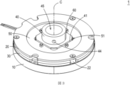
【課題】ブレーキパッドの回転過程における摩耗及び騒音の発生を避ける、回転モータに適用されるブレーキ装置を提供する。【解決手段】ブレーキ装置1は、ベース10、上板20、スライド板30、伝達部材40、ブレーキパッド50、接続部材60、プレート本体70及び弾性要素80を含む。回転軸90はベースを軸方向に貫通している。スライド板はベースと上板との間に設置され、駆動モジュール11の駆動によって軸方向に沿ってベースに貼り付けたり、ベースから離脱したりする。伝達部材は回転軸に套設固定され、かつ嵌合周縁41、位置制限部42及び貫通穴43を含む。ブレーキパッドはスライド板と上板との間に位置する。弾性要素はプレート本体と位置制限部の下面との間に設置され、弾性力を与えるように組み立てられることで、プレート本体はブレーキパッドを移動させて軸方向に沿って位置制限部の上面に当接させる。【選択図】図2A brake device applied to a rotary motor avoids wear and noise generation during the rotation process of brake pads. A brake device (1) includes a base (10), an upper plate (20), a slide plate (30), a transmission member (40), a brake pad (50), a connection member (60), a plate body (70) and an elastic element (80). The rotating shaft 90 axially passes through the base. The slide plate is installed between the base and the upper plate, and is axially attached to or detached from the base by driving the driving module 11 . The transmission member is mounted and fixed on the rotating shaft and includes a fitting peripheral edge 41 , a position limiting portion 42 and a through hole 43 . A brake pad is located between the slide plate and the top plate. The elastic element is installed between the plate body and the lower surface of the position limiting part, and is assembled to provide elastic force, so that the plate body moves the brake pad to hit the upper surface of the position limiting part along the axial direction. contact. [Selection drawing] Fig. 2
Description
本発明は、回転モータのブレーキ装置に関し、特にブレーキパッドの軸方向の位置制限を与え、ブレーキパッドの回転過程における摩耗及び騒音の発生を避けるための、回転モータに適用されるブレーキ装置に関するものである。
BACKGROUND OF THE
従来、回転モータのブレーキ装置は、動的タイプと保持タイプの二つの機能に分けられ、回転モータの電源が切った後、回転モータの回転子は、完全に停止する前に、慣性作用でしばらく回転することがある。多くの産業での回転モータの応用において、回転モータの電源が切った直後に停止する必要がある場合、それを実現するために動的ブレーキ装置が必要である。回転モータの回転が止まった後、負荷端が回転したり緩んだりしないように確保する必要がある場合は、保持ブレーキが必要である。一般的な回転モータのブレーキ装置は、ベース、スライド板、ブレーキパッド、上板及び角鉄(またはスプライン)からなり、ベースは回転モータの筐体に鎖定され、ベースにコイル及びばねで形成された駆動モジュールがある。駆動モジュールに通電すると、コイルの電磁により吸引力が発生し、スライド板が吸着されてベースに貼り付けられ、上板とスライド板との間のブレーキパッドに回転の自由度を持たせ、ブレーキパッドと角鉄(またはスプライン)及び回転子は組み立て後に一緒に回転する。駆動モジュールの電源が切ると、磁力による吸着を失ったスライド板はばねによって押し上げられ、スライド板がブレーキパッドを上板まで押し上げ、ブレーキパッドはスライド板と上板の挟みによって回転の自由度を失い、角鉄(またはスプライン)とにより回転子の回転を停止する。 Conventionally, the braking device of rotary motor is divided into two functions: dynamic type and holding type. It may rotate. In many industrial applications of rotary motors, when the rotary motor needs to stop immediately after it is powered down, a dynamic braking device is required to accomplish this. A holding brake is required when it is necessary to ensure that the load end does not rotate or come loose after the rotary motor has stopped rotating. A general rotary motor brake device consists of a base, a slide plate, a brake pad, an upper plate and a square iron (or spline), the base is chained to the rotary motor housing, and the base is formed of a coil and a spring. There is a drive module. When the drive module is energized, an attractive force is generated by the electromagnetic force of the coil, and the slide plate is attracted and attached to the base, allowing the brake pad between the upper plate and the slide plate to have a degree of freedom of rotation, and the brake pad and the square iron (or spline) and rotor rotate together after assembly. When the drive module is turned off, the slide plate, which has lost its magnetic attraction, is pushed up by the spring, and the slide plate pushes the brake pad up to the upper plate. , angle irons (or splines) to stop the rotation of the rotor.
しかし、駆動モジュールに通電しかつ回転子が回転する過程において、ブレーキパッドは軸方向の拘束がないため、重力の影響によりブレーキパッドが上下に移動したり、片寄りしたりすることで摩耗しやすい。摩耗により騒音や破片が発生する可能性があり、軽い場合は軸受及びエンコーダが汚染され、厳重な場合はブレーキが機能しなくなる。 However, in the process of energizing the drive module and rotating the rotor, the brake pads are not constrained in the axial direction. . The wear can create noise and debris, and if it is light it will foul the bearings and encoder, and if it is severe it will cause the brakes to fail.
かかる事情に鑑み、ブレーキパッドの軸方向の位置制限を与え、ブレーキパッドの回転過程における摩耗及び騒音の発生を避けて、先行技術の欠如を解決するために、回転モータに適用されるブレーキ装置を提供する必要がある。 In view of this situation, in order to provide the axial position limit of the brake pad, avoid wear and noise generation in the process of rotating the brake pad, and solve the lack of prior art, a brake device applied to the rotary motor is proposed. need to provide.
本発明の目的は、ブレーキパッドの軸方向の位置制限構造により、ブレーキパッドの回転過程における摩耗及び騒音の発生を避ける、回転モータに適用されるブレーキ装置を提供することにある。軸方向の位置制限構造は、プレート本体、接続部材及び弾性要素を追加することによって実現することができる。プレート本体とブレーキパッドは、接続部材を介して一定の軸方向の高さを維持し、弾性要素がプレート本体と伝達部材との間に弾性力を与えることで、プレート本体はブレーキパッドを移動させて軸方向に沿って伝達部材に当接させる。ブレーキパッドが伝達部材に軸方向に当接して軸方向の拘束を形成するため、伝達部材がブレーキパッドを回転させる時、重力の影響によりブレーキパッドが上下に移動したり、片寄りしたりすることによる摩耗は発生しにくくなるとともに、騒音及び破片の発生も避ける。 SUMMARY OF THE INVENTION It is an object of the present invention to provide a braking device applied to a rotary motor, which avoids wear and noise during the rotation process of the brake pad by means of an axial position limiting structure of the brake pad. Axial position limiting structures can be realized by adding plate bodies, connecting members and elastic elements. The plate body and the brake pad maintain a constant axial height through the connecting member, and the elastic element imparts an elastic force between the plate body and the transmission member, causing the plate body to move the brake pad. is brought into contact with the transmission member along the axial direction. Since the brake pads axially abut against the transmission member to form an axial constraint, when the transmission member rotates the brake pads, the force of gravity will prevent the brake pads from moving up and down or shifting to one side. It is less likely to cause wear due to friction, and also avoids noise and debris generation.
本発明の別の目的は、回転モータに適用されるブレーキ装置を提供することにある。ブレーキパッドに対してプレート本体、接続部材及び弾性要素を追加することによって実現された軸方向の位置制限構造と、ベース、上板及びスライド板から構築されたブレーキ構造とは、互いにずれて設置されることができる。プレート本体、接続部材及び弾性要素が、例えばベース中空部に収納されているため、軸方向の位置制限構造の設置は、構造全体の寸法を増加させることがなく、ブレーキ装置の安定性及び製品競争力を効果的に向上させる。 Another object of the present invention is to provide a braking device applied to a rotary motor. The axial position limiting structure realized by adding the plate body, the connecting member and the elastic element to the brake pad and the brake structure constructed from the base, the upper plate and the slide plate are installed offset from each other. can Since the plate body, the connecting member and the elastic element are housed, for example, in the hollow part of the base, the installation of the axial position limiting structure does not increase the dimensions of the whole structure, thus improving the stability and product competitiveness of the braking device. Effectively improve power.
前記目的を達成するために、本発明は、回転軸にブレーキをかけるように組み立てられる回転モータのブレーキ装置を提供する。ブレーキ装置は、ベース、上板、スライド板、伝達部材、ブレーキパッド、複数の接続部材、プレート本体及び複数の弾性要素を含む。ベースは駆動モジュール及びベース中空部を含み、回転軸はベース中空部を軸方向に貫通している。上板はベースと空間的に対応しており、かつ軸方向に沿って間隔をおいてベースに設置されている。スライド板はベースと上板との間に設置され、駆動モジュールの駆動によって軸方向に沿ってベースに貼り付けたり、ベースから離脱したりする。伝達部材は回転軸に套設固定されて、回転軸と同期して回転し、伝達部材は嵌合周縁、位置制限部及び複数の貫通穴を含み、位置制限部は回転軸の径方向に沿って嵌合周縁から外側に突出しており、複数の貫通穴は軸方向に沿って位置制限部を貫通している。ブレーキパッドは軸方向に沿って伝達部材の嵌合周縁に嵌合設置され、伝達部材の嵌合周縁と噛合しており、かつ位置制限部の上面に載せられ、ブレーキパッドはスライド板と上板との間に位置し、駆動モジュールがスライド板を駆動してベースから離脱させると、ブレーキパッドはスライド板と上板によって挟まれて、伝達部材と回転軸を同期して静止するように阻止する。駆動モジュールがスライド板を駆動してベースに貼り付けると、ブレーキパッドはスライド板及び上板と互いに分離し、かつ伝達部材の駆動によって回転する。プレート本体はブレーキパッドと空間的に対応しており、複数の接続部材は、それぞれ複数の貫通穴を通ってプレート本体とブレーキパッドとの間に接続されている。各弾性要素は接続部材に対応して套設され、かつプレート本体と位置制限部の下面との間に設置され、弾性力を与えるように組み立てられることで、プレート本体はブレーキパッドを移動させて軸方向に沿って位置制限部の上面に当接させる。 To achieve the above object, the present invention provides a rotary motor braking device which is assembled to brake a rotary shaft. The brake device includes a base, an upper plate, a slide plate, a transmission member, brake pads, a plurality of connecting members, a plate body and a plurality of elastic elements. The base includes a drive module and a base hollow, and the rotating shaft extends axially through the base hollow. The top plate spatially corresponds to the base and is axially spaced from the base. The slide plate is installed between the base and the upper plate, and is attached to or detached from the base along the axial direction by being driven by the driving module. The transmission member is mounted and fixed on the rotating shaft and rotates in synchronism with the rotating shaft, the transmitting member includes a fitting peripheral edge, a position restricting portion and a plurality of through holes, the position restricting portion extending along the radial direction of the rotating shaft. The plurality of through holes extend axially through the position limiting portion. A brake pad is axially fitted and installed on the fitting peripheral edge of the transmission member, is engaged with the fitting peripheral edge of the transmission member, and is placed on the upper surface of the position limiting portion, and the brake pad is mounted on the slide plate and the upper plate. When the drive module drives the slide plate away from the base, the brake pad is sandwiched between the slide plate and the upper plate to prevent the transmission member and the rotating shaft from being synchronously stationary. . When the driving module drives the slide plate to stick to the base, the brake pad separates from the slide plate and the upper plate and rotates by driving the transmission member. The plate body spatially corresponds to the brake pad, and the plurality of connecting members are connected between the plate body and the brake pad through the plurality of through holes, respectively. Each elastic element is installed correspondingly to the connecting member and installed between the plate body and the lower surface of the position limiting part, and is assembled so as to provide elastic force, so that the plate body moves the brake pad. It is brought into contact with the upper surface of the position limiting portion along the axial direction.
一実施形態では、駆動モジュールはばね要素及びコイル要素を含み、ばね要素はベースとスライド板との間に設置され、推力を与えるように組み立てられて、スライド板を駆動してベースから離脱させ、コイル要素はベース内に埋設され、通電時に磁気吸引力を発生させて、スライド板を駆動して推力に抵抗し、ベースに貼り付ける。 In one embodiment, the drive module includes a spring element and a coil element, the spring element positioned between the base and the slide plate and assembled to provide a thrust force to drive the slide plate away from the base; The coil element is embedded in the base, generates magnetic attraction force when energized, drives the slide plate to resist thrust, and sticks to the base.
一実施形態では、接続部材はロックボルト及びブッシングを含み、ブッシングは対応する貫通穴を通ってブレーキパッドとプレート本体との間に接続され、ロックボルトはブッシングを通ってブレーキパッドとプレート本体をロックする。 In one embodiment, the connecting member includes a lock bolt and a bushing, the bushing being connected between the brake pad and the plate body through corresponding through holes, and the lock bolt passing through the bushing to lock the brake pad and the plate body. do.
一実施形態では、ブッシングは、位置制限部の上面から下面までの距離よりも大きい軸方向の高さを有する。 In one embodiment, the bushing has an axial height greater than the distance from the top surface to the bottom surface of the position limiter.
一実施形態では、弾性要素は、ブッシングの外周縁に套設された圧縮ばねを含み、プレート本体と位置制限部の下面との間に弾性力を与える。 In one embodiment, the elastic element includes a compression spring mounted on the outer periphery of the bushing to provide elastic force between the plate body and the lower surface of the position limiter.
一実施形態では、ブレーキパッドは、伝達部材の複数の貫通穴と空間的に対応する複数の第一接続穴を含み、プレート本体は、伝達部材の複数の貫通穴と空間的に対応する複数の第二接続穴を有し、ロックボルトは、対応する第一接続穴、対応するブッシング及び対応する第二接続穴を介して、ブレーキパッドとプレート本体をロックし、第一接続穴の穴径及び第二接続穴の穴径はブッシングの管径よりも小さい。 In one embodiment, the brake pad includes a plurality of first connection holes spatially corresponding to the plurality of through holes of the transmission member, and the plate body includes a plurality of first connection holes spatially corresponding to the plurality of through holes of the transmission member. With a second connection hole, the lock bolt locks the brake pad and the plate body through the corresponding first connection hole, the corresponding bushing and the corresponding second connection hole, the hole diameter of the first connection hole and The hole diameter of the second connecting hole is smaller than the pipe diameter of the bushing.
一実施形態では、伝達部材は角鉄またはスプラインである。 In one embodiment, the transmission member is a square iron or spline.
一実施形態では、ベースと、位置制限部、プレート本体、複数の接続部材及び弾性要素とは軸方向にずれて設置されている。 In one embodiment, the base, the position limiter, the plate body, the plurality of connecting members and the elastic elements are axially offset.
一実施形態では、伝達部材は、回転軸の径方向に沿って延びる少なくとも一つのロック穴を含み、ブレーキ装置は少なくとも一つのロック部材を含み、少なくとも一つのロック部材は、少なくとも一つのロック穴を通って伝達部材を回転軸にロックする。 In one embodiment, the transmission member includes at least one lock hole extending along the radial direction of the rotating shaft, the brake device includes at least one lock member, and the at least one lock member defines the at least one lock hole. to lock the transmission member to the rotating shaft.
一実施形態では、複数の接続部材、弾性要素及び複数の貫通穴は同じ数Nを有し、Nは整数であり、かつNは3以上である。 In one embodiment, the plurality of connecting members, elastic elements and plurality of through holes have the same number N, N being an integer and N being 3 or greater.
一実施形態では、複数の貫通穴は、回転軸を中心として位置制限部に等距離に環状設置されている。 In one embodiment, the plurality of through-holes are arranged equidistantly annularly around the axis of rotation in the position limiter.
一実施形態では、ブレーキパッドは嵌合口を有し、ブレーキパッドは嵌合口を介して伝達部材の嵌合周縁に套設され、ブレーキパッドの嵌合口は、伝達部材の嵌合周縁より大きいまたは等しい。 In one embodiment, the brake pad has a fitting opening, the brake pad is fitted through the fitting opening to a fitting perimeter of the transmission member, the fitting opening of the brake pad being greater than or equal to the fitting perimeter of the transmission member. .
一実施形態では、スライド板はスライド板中空部を有し、上板は上板中空部を有し、プレート本体はプレート本体中空部を有し、回転軸は、ベース中空部、スライド板中空部、上板中空部及びプレート本体中空部を貫通している。 In one embodiment, the slide plate has a slide plate hollow portion, the upper plate has an upper plate hollow portion, the plate body has a plate body hollow portion, and the rotating shaft includes the base hollow portion and the slide plate hollow portion. , the hollow portion of the upper plate and the hollow portion of the plate body.
一実施形態では、上板、スライド板、プレート本体及びベースは環状構造である。 In one embodiment, the top plate, slide plate, plate body and base are annular structures.
一実施形態では、ブレーキ装置は複数の仕切柱をさらに含み、複数の仕切柱はベースと上板との間に接続され、かつ複数の仕切柱とスライド板はずれて設置されている。 In one embodiment, the braking device further includes a plurality of partition posts, the plurality of partition posts are connected between the base and the upper plate, and the plurality of partition posts and the slide plate are offset.
本発明の特徴と利点を示すいくつかの典型的な実施形態について、後述の説明において記述する。本発明は異なる態様において様々な変化を有することができ、いずれも本発明の範囲から逸脱することなく、かつその説明及び図面は本質的に例示するために用いられものであり、本発明を限定する意図はないことを理解されたい。例えば、本開示の以下の内容において、第一特徴を第二特徴の上または上方に設置することが記述される場合、設置された上記第一特徴が上記第二特徴と直接接触している実施形態を含み、追加の特徴を上記第一特徴と上記第二特徴との間に設置することで、上記第一特徴が上記第二特徴と直接接触していない実施形態も含むことを示す。さらに、本開示の異なる実施形態において、重複する参照符号及び/または記号を使用可能である。これらの重複は簡潔化と明確化の目的で、各実施形態及び/または前記外観構造間の関係を制限するために使用されるものではない。また、図面における構成要素または特徴要素と他の(複数の)構成要素または(複数の)特徴要素との関係を簡易に記述するために、例えば、「...の下に」、「下方」、「より下部」、「上方」、「より上部」、及び類似する用語などの空間関連の用語を用いることができる。図面に示される方位に加えて、空間関連の用語は、使用中または作動中の装置の異なる方位を含むために用いられる。前記装置は、別途に位置決めされ(例えば、90度回転または他の方位に位置し)てもよく、それに応じて使用される空間関連の用語の記述を解釈する。さらに、一つの構成要素が他の構成要素に「接続」または「結合」すると称する場合、他の構成要素に直接的に接続または結合することができ、または介在構成要素が存在しうる。本開示の広範な範囲の数値範囲とパラメータは近似値であるが、具体的な例においてできる限り正確に数値を記述する。さらに、「第一」、「第二」、「第三」などの用語は、特許請求の範囲において異なる構成要素を記述するために用いられることができるが、これらの構成要素はこれらの用語によって限定されるべきではなく、実施形態において記述されたこれらの構成要素は異なる構成要素記号によって示されることを理解されたい。これらの用語は、異なる構成要素を区別するためのものである。例えば、第一構成要素は第二構成要素と称されることができ、同様に、第二構成要素も第一構成要素と称されることができ、実施形態の範囲から逸脱することがない。このように使用される用語「及び/または」には、一つまたは複数の列挙された項目のいずれかまたはすべての組み合わせが含まれている。作動例/作業例中以外に、または明示的に規定されない限り、本明細書で開示されるすべての数値範囲、量、値、及びパーセンテージ(例えば、角度、持続時間、温度、作動条件、量比、及び類似するもののパーセンテージなど)は、すべての実施形態において用語の「約」または「実質的に」によって修飾されるものと理解されるべきである。それに応じて、反対の指示がない限り、本開示及び添付の特許請求の範囲に記述される数値パラメータは、必要に応じて変更できる近似値である。例えば、各数値パラメータは、少なくとも記述される有効桁数の数字に基づいて、通常の丸めの原則を適用することによって解釈されるべきである。本明細書において、範囲は一つのエンドポイントからもう一つのエンドポイントまで、または二つのエンドポイント間として表現することができる。本明細書に開示されるすべての範囲は、特に規定がない限り、エンドポイントを含む。 Several exemplary embodiments that illustrate features and advantages of the invention are described in the following description. The present invention is capable of various changes in different aspects, all without departing from the scope of the invention, and the description and drawings are intended to be illustrative in nature and not limiting of the invention. It should be understood that there is no intention to For example, in the following content of this disclosure, when placing a first feature on or above a second feature is described, implementations in which said first feature is placed in direct contact with said second feature The inclusion of features and the placement of additional features between the first and second features indicates that the first feature does not directly contact the second feature to include embodiments. Moreover, duplicate reference signs and/or symbols may be used in different embodiments of the present disclosure. These duplications are for purposes of brevity and clarity and are not used to limit the relationship between each embodiment and/or the features described above. In addition, in order to simply describe the relationship between a component or feature element in a drawing and other component(s) or feature(s), for example, "below", "below", etc. , “lower,” “upper,” “upper,” and similar terms may be used. In addition to the orientations shown in the drawings, spatially related terms are used to include different orientations of the device during use or operation. The device may be positioned differently (eg, rotated 90 degrees or positioned at other orientations) and interprets the description of spatially related terms used accordingly. Further, when one component is referred to as being “connected” or “coupled” to another component, it may be directly connected or coupled to the other component or there may be intervening components. The numerical ranges and parameters for the broad ranges of this disclosure are approximations but set forth the numerical values as precisely as possible in the specific examples. Further, terms such as "first," "second," and "third" may be used in the claims to describe different elements, which elements are referred to by these terms. It should not be limiting and should be understood that those components described in the embodiments are indicated by different component designations. These terms are used to distinguish different components. For example, a first component could be referred to as a second component, and similarly a second component could be referred to as a first component without departing from the scope of the embodiments. The term "and/or" as used in this manner includes any and all combinations of one or more of the listed items. All numerical ranges, amounts, values, and percentages disclosed herein (e.g., angles, durations, temperatures, operating conditions, quantitative ratios, , and percentages of the like) are to be understood to be modified by the term "about" or "substantially" in all embodiments. Accordingly, unless indicated to the contrary, the numerical parameters set forth in this disclosure and appended claims are approximations that may, if necessary, change. For example, each numerical parameter should be interpreted by applying normal rounding rules based on at least the number of significant digits described. Ranges can be expressed herein as from one endpoint to another endpoint or between the two endpoints. All ranges disclosed herein are inclusive of the endpoints unless otherwise specified.
図1から図8は、本発明の回転モータに適用されるブレーキ装置を示す。本実施形態では、回転モータのブレーキ装置(または単にブレーキ装置という)1は、例えば回転モータの回転軸90にブレーキをかけるように組み立てられる。ブレーキ装置1は、ベース10、上板20、スライド板30、伝達部材40、ブレーキパッド50、接続部材60、プレート本体70及び弾性要素80を含む。本実施形態では、ベース10は、例えば環状構造であり、かつ駆動モジュール11及びベース中空部12を含む。駆動モジュール11は、例えば、それぞれ推力及び磁気吸引力を与えるように組み立てられているばね要素(図示せず)及びコイル要素(図示せず)を含み、本発明はこれに限定されない。本実施形態では、回転軸90は軸方向Cに沿ってベース10のベース中空部12を貫通している。上板20は、例えば環状構造であり、上板中空部21を有する。上板20はベース10と空間的に対応しており、かつ軸方向Cに沿って間隔をおいてベース10に設置されている。同様に、回転軸90は、例えば軸方向Cに沿って上板20の上板中空部21を貫通している。本実施形態では、ブレーキ装置1は、例えば複数の仕切柱22をさらに含み、上板20とベース10が一定の間隔の高さを維持するように、複数の仕切柱22はベース10と上板20との間に接続されている。さらに、スライド板30はベース10及び上板20と空間的に対応しており、例えば環状構造であり、スライド板中空部31を有する。回転軸90は、例えば軸方向Cに沿ってスライド板30のスライド板中空部31を貫通している。本実施形態では、スライド板30がベース10と上板20に対して軸方向Cにスライドすることができるように、スライド板30はベース10と上板20との間に設置され、かつ複数の仕切柱22とスライド板30はずれて配列設置されている。
1 to 8 show a braking device applied to the rotary motor of the present invention. In the present embodiment, a rotary motor braking device (or simply referred to as a braking device) 1 is assembled to brake, for example, a rotating
駆動モジュール11のばね要素は、例えばベース10とスライド板30との間に設置され、推力を与えるように組み立てられて、スライド板30を駆動してベース10から離脱させることを説明すべきである。さらに、駆動モジュール11のコイル要素は、例えばベース10内に埋設され、通電時に磁気吸引力を発生させて、スライド板30を駆動してばね要素によって提供された推力に対抗し、ベース10に貼り付ける。言い換えれば、本実施形態では、スライド板30は、駆動モジュール11の駆動によって軸方向Cに沿ってベース10に貼り付けたり、ベース10から離脱したりすることができる。もちろん、本発明は、駆動モジュール11がスライド板30を駆動してスライドさせる方式に限定されるものではない。
It should be mentioned that the spring elements of the
本実施形態では、伝達部材40は、例えば角鉄またはスプラインであり、回転軸90に套設固定されて、回転軸90と同期して回転する。伝達部材40は、嵌合周縁41、位置制限部42、複数の貫通穴43及び軸穴45を含む。伝達部材40は、軸穴45を介して回転軸90に套設固定されている。嵌合周縁41は、ブレーキパッド50に係合するように組み立てられている。位置制限部42は、回転軸90の径方向に沿って嵌合周縁41から外側に突出しており、例えば環状ボスを形成する。もちろん、位置制限部42の嵌合周縁41から外側に突出した部分は、実際の応用要求に応じて調整でき、本発明はこれに限定されない。本実施形態では、複数の貫通穴43は軸方向Cに沿って位置制限部42の上面421及び下面422を貫通している。ブレーキパッド50は嵌合口51を有する。ブレーキパッド50は嵌合口51を介して軸方向Cに沿って伝達部材40の嵌合周縁41に嵌合設置されている。本実施形態では、ブレーキパッド50の嵌合口51は、例えば伝達部材40の嵌合周縁41より大きいまたは等しく、これによって、伝達部材40が回転軸90によって駆動されると、ブレーキパッド50の嵌合口51は伝達部材40の嵌合周縁41と噛合しており、かつブレーキパッド50は位置制限部42の上面421に載せられる。
In this embodiment, the
本実施形態では、ブレーキパッド50はスライド板30と上板20との間に位置し、駆動モジュール11がスライド板30を駆動してベース10から離脱させると、ブレーキパッド50はスライド板30と上板20によって挟まれて、伝達部材40と回転軸90を同期して静止するように阻止する。駆動モジュール11がスライド板30を駆動してベース10に貼り付けると、ブレーキパッド50とスライド板30及び上板20は互いに分離し、ブレーキパッド50は回転の自由度を回復し、伝達部材40の駆動によって回転することができる。
In this embodiment, the
本実施形態では、プレート本体70はブレーキパッド50と空間的に対応しており、複数の接続部材60は、それぞれ伝達部材40の複数の貫通穴43を通ってプレート本体70とブレーキパッド50との間に接続されていることに注意すべきである。さらに、弾性要素80は接続部材60に套設され、かつプレート本体70と伝達部材40の位置制限部42の下面422との間に設置され、弾性力を与えるように組み立てられている。言い換えれば、プレート本体70とブレーキパッド50は、接続部材60を介して一定の軸方向の高さHを維持し、弾性要素80がプレート本体70と伝達部材40の位置制限部42の下面422との間に弾性力を与えることで、プレート本体70はブレーキパッド50を移動させて軸方向Cに沿って伝達部材40の位置制限部42の上面421に当接させる。ブレーキパッド50が軸方向Cに伝達部材40の位置制限部42に当接して軸方向Cの拘束を形成するため、伝達部材40がブレーキパッド50を回転させる時、重力の影響によりブレーキパッド50が上下に移動したり、片寄りしたりすることによる摩耗は発生しにくくなるとともに、騒音及び破片の発生も避ける。
In this embodiment, the
本実施形態では、複数の接続部材60、複数の弾性要素80及び伝達部材40の複数の貫通穴43は同じ数Nを有し、Nは整数であり、かつNは3以上である。これにより、複数の同じ高さの接続部材60によって接続されたブレーキパッド50とプレート本体70は、軸方向Cに一定の高さ差を維持することができる。本実施形態では、4つの貫通穴43は、例えば回転軸90を中心として位置制限部42に等距離に環状設置されている。他の実施形態では、接続部材60と貫通穴43の数及び配列は、実際の応用要求に応じて調整でき、本発明はこれに限定されない。
In this embodiment, the plurality of connecting
さらに、本実施形態では、各接続部材60は、ロックボルト61及びブッシング62を含み、ブッシング62は、例えば管状であり、伝達部材40の位置制限部42における対応する貫通穴43を通って、ブレーキパッド50とプレート本体70との間に接続され、ロックボルト61はブッシング62を通ってブレーキパッド50とプレート本体70をロックする。本実施形態では、ブッシング62は、例えば、伝達部材40の位置制限部42の上面421から下面422までの距離よりも大きい軸方向の高さHを有する。すなわち、ブッシング62の軸方向の高さHは、位置制限部42の厚さTよりも大きい。なお、本実施形態では、ブレーキパッド50は、伝達部材40の複数の貫通穴43と空間的に対応する複数の第一接続穴52を含む。プレート本体70は、伝達部材40の複数の貫通穴43と空間的に対応する複数の第二接続穴72を有する。各接続部材60のロックボルト61は、対応する第一接続穴52、対応するブッシング62及び対応する第二接続穴72を介して、例えば両端のナットでブレーキパッド50とプレート本体70をロックする。第一接続穴52の穴径及び第二接続穴72の穴径dは、いずれもブッシング62の管径Dより小さい。これにより、ロックボルト61が例えば両端のナットでブレーキパッド50とプレート本体70をロックする時、ブッシング62は、ブレーキパッド50とプレート本体70との間に挟まれ、ブレーキパッド50とプレート本体70は、複数のブッシング62の支持及び接続により、一定の軸方向の高さHを維持することができる。
Furthermore, in this embodiment, each connecting
一方、本実施形態では、弾性要素80は、例えば複数の圧縮ばねをさらに含み、各圧縮ばねは、例えば、ブッシング62の外周縁に套設されて、プレート本体70と位置制限部42の下面422の間に均一で安定した弾性力を与え、プレート本体70は、接続部材60によりブレーキパッド50を移動させて軸方向Cに沿って位置制限部42の上面421に当接させる。もちろん、本発明は弾性要素80の形態に限定されるものではない。他の実施形態では、弾性要素80は、例えばブッシング62の外周縁に套設されるのではなく、プレート本体70と伝達部材40との間に設置されてもよく、弾性力を与えることにより、プレート本体70は、接続部材60によりブレーキパッド50を移動させて軸方向Cに沿って位置制限部42の上面421に当接させることができる。本発明はこれに限定されず、かつ説明を省略する。
On the other hand, in the present embodiment, the
本実施形態では、ベース10、上板20、スライド板30、伝達部材40及びブレーキパッド50が、回転軸90のブレーキ構造として構築され、回転軸90のブレーキ機能を与えることを説明すべきである。本発明のブレーキ装置1は、ブレーキパッド50に対してプレート本体70、接続部材60及び弾性要素80をさらに追加し、ブレーキパッド50の軸方向の位置制限構造をさらに構築する。本実施形態では、ベース10、スライド板30及び上板20はいずれも環状構造であり、回転軸90はベース中空部12、スライド板中空部31及び上板中空部21を貫通している。ベース10、スライド板30及び上板20は、回転軸90の回転に影響を及ぼさない。ブレーキパッド50に対してプレート本体70、接続部材60及び弾性要素80を追加することによって実現された軸方向の位置制限構造と、ベース10、上板20及びスライド板30から構築されたブレーキ構造とは、互いにずれて設置されることができることに注意すべきである。本実施形態では、ベース10と、位置制限部42、プレート本体70、複数の接続部材60及び弾性要素80とは軸方向Cにずれて設置されている。位置制限部42、プレート本体70、複数の接続部材60及び弾性要素80は、さらに例えばベース中空部12、スライド板中空部31及び上板中空部21によって連通された空間に収納されている。ブレーキパッド50に対してプレート本体70、接続部材60及び弾性要素80を追加することによって実現された軸方向の位置制限構造と、ベース10、上板20及びスライド板30から構築されたブレーキ構造とは、互いにずれて設置されることができる。したがって、軸方向の位置制限構造の設置は、構造全体の寸法を増加させることがなく、ブレーキ装置1の安定性及び製品競争力を効果的に向上させる。もちろん、他の実施形態では、ブレーキパッド50に対してプレート本体70、接続部材60及び弾性要素80を追加することによって実現された軸方向の位置制限構造は、ベース中空部12、スライド板中空部31及び上板中空部21によって連通された空間の外に構築されてもよい。本発明はこれに限定されず、かつ説明を省略する。
It should be explained that in this embodiment, the
さらに、本実施形態では、伝達部材40は、回転軸90の径方向に沿って延びる少なくとも一つのロック穴44をさらに含み、ブレーキ装置1は少なくとも一つのロック部材(図示せず)、例えばねじを含む。少なくとも一つのロック部材は少なくとも一つのロック穴44を通って、伝達部材40を回転軸90にロックする。これにより、伝達部材40が軸穴45を介して回転軸90に套設される時、さらに回転軸90にロックされて、伝達部材40と回転軸90は同期して動作することができる。もちろん、他の実施形態では、伝達部材40と回転軸90の嵌合固定は、さらに係合溝または係合キーの形態によって達成することができる。本発明はこれに限定されず、かつ説明を省略する。
Furthermore, in this embodiment, the
上記のように、本発明は、ブレーキパッドの軸方向の位置制限構造により、ブレーキパッドの回転過程における摩耗及び騒音の発生を避ける、回転モータに適用されるブレーキ装置を提供する。軸方向の位置制限構造は、プレート本体、接続部材及び弾性要素を追加することにより実現することができる。プレート本体とブレーキパッドは、接続部材を介して一定の軸方向の高さを維持し、弾性要素は、プレート本体がブレーキパッドを移動させて軸方向に沿って伝達部材に当接させるように、プレート本体と伝達部材との間に弾性力を与える。ブレーキパッドが伝達部材に軸方向に当接して軸方向の拘束を形成するため、伝達部材がブレーキパッドを回転させる時、重力の影響によりブレーキパッドが上下に移動したり、片寄りしたりすることによる摩耗は発生しにくくなるとともに、騒音及び破片の発生も避ける。さらに、ブレーキパッドに対してプレート本体、接続部材及び弾性要素を追加することによって実現された軸方向の位置制限構造と、ベース、上板及びスライド板から構築されたブレーキ構造とは、互いにずれて設置されることができる。プレート本体、接続部材及び弾性要素は、例えばベース中空部に収納されるため、軸方向の位置制限構造の設置は、構造全体の寸法を増加させることがなく、ブレーキ装置の安定性及び製品競争力を効果的に向上させる。 As described above, the present invention provides a braking device applied to a rotary motor, which avoids wear and noise generation during the rotation process of the brake pad through the axial position limit structure of the brake pad. Axial position limiting structures can be realized by adding plate bodies, connecting members and elastic elements. The plate body and the brake pad maintain a constant axial height through the connecting member, and the elastic element causes the plate body to move the brake pad to abut the transmission member along the axial direction. An elastic force is applied between the plate body and the transmission member. Since the brake pads axially abut against the transmission member to form an axial constraint, when the transmission member rotates the brake pads, the force of gravity will prevent the brake pads from moving up and down or shifting to one side. It is less likely to cause wear due to friction, and also avoids noise and debris generation. Furthermore, the axial position limiting structure realized by adding the plate body, the connecting member and the elastic element to the brake pad and the brake structure constructed from the base, the top plate and the slide plate are offset from each other. can be installed. Since the plate body, the connecting member and the elastic element are housed, for example, in the hollow part of the base, the installation of the axial position limiting structure does not increase the overall size of the structure, thus improving the stability and product competitiveness of the braking device. effectively improve
本発明は、当業者なら様々な修正を加えることができるが、特許請求の範囲によって定義される範囲から逸脱することはない。 The present invention is susceptible to various modifications by those skilled in the art without departing from the scope defined by the claims.
1... ブレーキ装置
10... ベース
11... 駆動モジュール
12... ベース中空部
20... 上板
21... 上板中空部
22... 仕切柱
30... スライド板
31... スライド板中空部
40... 伝達部材
41... 嵌合周縁
42... 位置制限部
421... 上面
422... 下面
43... 貫通穴
44... ロック穴
45... 軸穴
50... ブレーキパッド
51... 嵌合口
52... 第一接続穴
60... 接続部材
61... ロックボルト
62... ブッシング
70... プレート本体
71... プレート本体中空部
72... 第二接続穴
80... 弾性要素
90... 回転軸
C... 軸方向
d... 穴径
D... 管径
H... 軸方向の高さ
T... 厚さ
DESCRIPTION OF
Claims (12)
駆動モジュール及びベース中空部を含み、前記回転軸が前記ベース中空部を軸方向に貫通している、ベースと、
前記ベースと空間的に対応しており、かつ前記軸方向に沿って間隔をおいて前記ベースに設置された、上板と、
前記ベースと前記上板との間に設置され、前記駆動モジュールの駆動によって前記軸方向に沿って前記ベースに貼り付けたり、前記ベースから離脱したりする、スライド板と、
前記回転軸に套設固定されて、前記回転軸と同期して回転し、嵌合周縁、位置制限部及び複数の貫通穴を含み、前記位置制限部が前記回転軸の径方向に沿って前記嵌合周縁から外側に突出しており、前記複数の貫通穴が前記軸方向に沿って前記位置制限部を貫通している、伝達部材と、
前記軸方向に沿って前記伝達部材の前記嵌合周縁に嵌合設置され、前記伝達部材の前記嵌合周縁と噛合しており、かつ前記位置制限部の上面に載せられるブレーキパッドであって、前記ブレーキパッドが、前記スライド板と前記上板との間に位置し、前記駆動モジュールが前記スライド板を駆動して前記ベースから離脱させると、前記ブレーキパッドが前記スライド板と前記上板によって挟まれて、前記伝達部材と前記回転軸を同期して静止するように阻止し、前記駆動モジュールが前記スライド板を駆動して前記ベースに貼り付けると、前記ブレーキパッドが前記スライド板及び前記上板と互いに分離し、かつ前記伝達部材の駆動によって回転する、ブレーキパッドと、
前記ブレーキパッドと空間的に対応する、プレート本体と、
それぞれ前記複数の貫通穴を通って前記プレート本体と前記ブレーキパッドとの間に接続される、複数の接続部材と、
複数の弾性要素であって、各弾性要素が前記接続部材に対応して套設され、かつ前記プレート本体と前記位置制限部の下面との間に設置され、弾性力を与えるように組み立てられることで、前記プレート本体が前記ブレーキパッドを移動させて前記軸方向に沿って前記位置制限部の前記上面に当接させる、複数の弾性要素と、
を含むことを特徴とする、回転モータのブレーキ装置。 A rotary motor braking device assembled to brake a rotary shaft, comprising:
a base including a drive module and a base hollow, wherein the axis of rotation extends axially through the base hollow;
a top plate spatially corresponding to and spaced from the base along the axial direction;
a slide plate installed between the base and the upper plate, which is attached to or detached from the base along the axial direction by being driven by the drive module;
It is installed and fixed to the rotating shaft, rotates in synchronization with the rotating shaft, and includes a fitting peripheral edge, a position restricting portion, and a plurality of through holes, and the position restricting portion extends along the radial direction of the rotating shaft. a transmission member protruding outward from the fitting peripheral edge, the plurality of through holes penetrating the position limiting portion along the axial direction;
A brake pad that is fitted to the fitting peripheral edge of the transmission member along the axial direction, is engaged with the fitting peripheral edge of the transmission member, and is placed on the upper surface of the position limiting portion, The brake pad is positioned between the slide plate and the top plate, and when the driving module drives the slide plate to separate from the base, the brake pad is sandwiched between the slide plate and the top plate. and prevents the transmission member and the rotating shaft from being synchronously stationary, and the driving module drives the slide plate to attach it to the base, so that the brake pad engages the slide plate and the upper plate. a brake pad separated from each other and rotated by driving the transmission member;
a plate body spatially corresponding to the brake pad;
a plurality of connection members each connected between the plate body and the brake pad through the plurality of through holes;
a plurality of elastic elements, each elastic element being installed correspondingly to the connecting member and installed between the plate body and the lower surface of the position limiting part, and assembled to provide elastic force; a plurality of elastic elements for causing the plate body to move the brake pad to contact the upper surface of the position limiting portion along the axial direction;
A braking device for a rotary motor, comprising:
Applications Claiming Priority (2)
| Application Number | Priority Date | Filing Date | Title |
|---|---|---|---|
| CN202210033758.X | 2022-01-12 | ||
| CN202210033758.XA CN116470695A (en) | 2022-01-12 | 2022-01-12 | Braking device of rotary motor |
Publications (2)
| Publication Number | Publication Date |
|---|---|
| JP7249727B1 true JP7249727B1 (en) | 2023-03-31 |
| JP2023102739A JP2023102739A (en) | 2023-07-25 |
Family
ID=85772965
Family Applications (1)
| Application Number | Title | Priority Date | Filing Date |
|---|---|---|---|
| JP2022070802A Active JP7249727B1 (en) | 2022-01-12 | 2022-04-22 | Braking device for rotary motor |
Country Status (3)
| Country | Link |
|---|---|
| US (1) | US20230220890A1 (en) |
| JP (1) | JP7249727B1 (en) |
| CN (1) | CN116470695A (en) |
Citations (6)
| Publication number | Priority date | Publication date | Assignee | Title |
|---|---|---|---|---|
| EP1001508A2 (en) | 1998-11-16 | 2000-05-17 | Gibierre S.r.l. | Electromagnetic brake with two independent front disks |
| US20180172097A1 (en) | 2016-12-16 | 2018-06-21 | Ratier-Figeac Sas | Mechanical brake |
| JP2018528362A (en) | 2015-06-15 | 2018-09-27 | クノール−ブレミゼ ジュステーメ フューア ヌッツファーツォィゲ ゲーエムベーハーKNORR−BREMSE System fuer Nutzfahrzeuge GmbH | Disc brake and brake pad set for commercial vehicles |
| JP2018157722A (en) | 2017-03-21 | 2018-10-04 | Ntn株式会社 | Actuator |
| CN111211638A (en) | 2020-02-21 | 2020-05-29 | 中标(浙江)智能技术有限公司 | Airing machine direct current elevator motor, driving system and airing system |
| JP3232177U (en) | 2020-07-16 | 2021-05-27 | 台達電子工業股▲ふん▼有限公司Delta Electronics, Inc. | Motor device |
Family Cites Families (1)
| Publication number | Priority date | Publication date | Assignee | Title |
|---|---|---|---|---|
| JPH11230203A (en) * | 1998-02-13 | 1999-08-27 | Ogura Clutch Co Ltd | Nonexcitation operation type electromagnetic brake |
-
2022
- 2022-01-12 CN CN202210033758.XA patent/CN116470695A/en active Pending
- 2022-04-22 JP JP2022070802A patent/JP7249727B1/en active Active
- 2022-06-16 US US17/842,723 patent/US20230220890A1/en active Pending
Patent Citations (6)
| Publication number | Priority date | Publication date | Assignee | Title |
|---|---|---|---|---|
| EP1001508A2 (en) | 1998-11-16 | 2000-05-17 | Gibierre S.r.l. | Electromagnetic brake with two independent front disks |
| JP2018528362A (en) | 2015-06-15 | 2018-09-27 | クノール−ブレミゼ ジュステーメ フューア ヌッツファーツォィゲ ゲーエムベーハーKNORR−BREMSE System fuer Nutzfahrzeuge GmbH | Disc brake and brake pad set for commercial vehicles |
| US20180172097A1 (en) | 2016-12-16 | 2018-06-21 | Ratier-Figeac Sas | Mechanical brake |
| JP2018157722A (en) | 2017-03-21 | 2018-10-04 | Ntn株式会社 | Actuator |
| CN111211638A (en) | 2020-02-21 | 2020-05-29 | 中标(浙江)智能技术有限公司 | Airing machine direct current elevator motor, driving system and airing system |
| JP3232177U (en) | 2020-07-16 | 2021-05-27 | 台達電子工業股▲ふん▼有限公司Delta Electronics, Inc. | Motor device |
Also Published As
| Publication number | Publication date |
|---|---|
| JP2023102739A (en) | 2023-07-25 |
| US20230220890A1 (en) | 2023-07-13 |
| CN116470695A (en) | 2023-07-21 |
Similar Documents
| Publication | Publication Date | Title |
|---|---|---|
| JP7435028B2 (en) | clutch device | |
| EP2253866B1 (en) | Electrically operated linear actuator and electrically operated braking system | |
| US6971484B2 (en) | Electric disc brake | |
| US6702070B2 (en) | Integrated drive unit | |
| WO2001059320A1 (en) | Combined parking and service brake | |
| CN102213282A (en) | Cone brake no-back | |
| JP7249727B1 (en) | Braking device for rotary motor | |
| EP1801449B1 (en) | Ball ramp brake | |
| JP5390886B2 (en) | Power transmission device | |
| JP2007009801A (en) | Hydraulic motor | |
| JP2007500322A (en) | Axial adjustment device with disc spring type transducer | |
| JP5180958B2 (en) | Electrically actuated shaft brake with manual positive lock and rotation release and automatic reset mechanism | |
| JP2018179116A (en) | Wet brake | |
| JP2009085318A (en) | Torque fluctuation absorbing device | |
| KR20120002871A (en) | Clutch assembly for automatic transmissions | |
| TWI811951B (en) | Brake device of rotating motor | |
| CN211009660U (en) | High-reliability electromagnetic power-off brake | |
| JP2012175772A (en) | Electric linear motion actuator and electric disc brake device | |
| CN116457591A (en) | Brake device, drive unit and industrial device | |
| JP4610171B2 (en) | Differential equipment | |
| CN218987822U (en) | Hydraulic braking system for mining conveyor driving equipment and mining conveyor driving equipment | |
| JPH0141852B2 (en) | ||
| WO2021164196A1 (en) | Rotor assembly, water pump, and vehicle | |
| JP2009293703A (en) | Brake device | |
| JP2010045898A (en) | Electric linear-motion actuator and electric braking device |
Legal Events
| Date | Code | Title | Description |
|---|---|---|---|
| A621 | Written request for application examination |
Free format text: JAPANESE INTERMEDIATE CODE: A621 Effective date: 20220422 |
|
| TRDD | Decision of grant or rejection written | ||
| A01 | Written decision to grant a patent or to grant a registration (utility model) |
Free format text: JAPANESE INTERMEDIATE CODE: A01 Effective date: 20230228 |
|
| A61 | First payment of annual fees (during grant procedure) |
Free format text: JAPANESE INTERMEDIATE CODE: A61 Effective date: 20230319 |
|
| R150 | Certificate of patent or registration of utility model |
Ref document number: 7249727 Country of ref document: JP Free format text: JAPANESE INTERMEDIATE CODE: R150 |