JP2017514997A - Processing apparatus and processing method for pickling and phosphating metal parts - Google Patents
Processing apparatus and processing method for pickling and phosphating metal parts Download PDFInfo
- Publication number
- JP2017514997A JP2017514997A JP2016565183A JP2016565183A JP2017514997A JP 2017514997 A JP2017514997 A JP 2017514997A JP 2016565183 A JP2016565183 A JP 2016565183A JP 2016565183 A JP2016565183 A JP 2016565183A JP 2017514997 A JP2017514997 A JP 2017514997A
- Authority
- JP
- Japan
- Prior art keywords
- processing
- substance
- treatment
- phosphate
- reactant
- Prior art date
- Legal status (The legal status is an assumption and is not a legal conclusion. Google has not performed a legal analysis and makes no representation as to the accuracy of the status listed.)
- Pending
Links
Images


Classifications
-
- C—CHEMISTRY; METALLURGY
- C23—COATING METALLIC MATERIAL; COATING MATERIAL WITH METALLIC MATERIAL; CHEMICAL SURFACE TREATMENT; DIFFUSION TREATMENT OF METALLIC MATERIAL; COATING BY VACUUM EVAPORATION, BY SPUTTERING, BY ION IMPLANTATION OR BY CHEMICAL VAPOUR DEPOSITION, IN GENERAL; INHIBITING CORROSION OF METALLIC MATERIAL OR INCRUSTATION IN GENERAL
- C23C—COATING METALLIC MATERIAL; COATING MATERIAL WITH METALLIC MATERIAL; SURFACE TREATMENT OF METALLIC MATERIAL BY DIFFUSION INTO THE SURFACE, BY CHEMICAL CONVERSION OR SUBSTITUTION; COATING BY VACUUM EVAPORATION, BY SPUTTERING, BY ION IMPLANTATION OR BY CHEMICAL VAPOUR DEPOSITION, IN GENERAL
- C23C22/00—Chemical surface treatment of metallic material by reaction of the surface with a reactive liquid, leaving reaction products of surface material in the coating, e.g. conversion coatings, passivation of metals
- C23C22/05—Chemical surface treatment of metallic material by reaction of the surface with a reactive liquid, leaving reaction products of surface material in the coating, e.g. conversion coatings, passivation of metals using aqueous solutions
- C23C22/06—Chemical surface treatment of metallic material by reaction of the surface with a reactive liquid, leaving reaction products of surface material in the coating, e.g. conversion coatings, passivation of metals using aqueous solutions using aqueous acidic solutions with pH less than 6
- C23C22/07—Chemical surface treatment of metallic material by reaction of the surface with a reactive liquid, leaving reaction products of surface material in the coating, e.g. conversion coatings, passivation of metals using aqueous solutions using aqueous acidic solutions with pH less than 6 containing phosphates
- C23C22/08—Orthophosphates
-
- C—CHEMISTRY; METALLURGY
- C23—COATING METALLIC MATERIAL; COATING MATERIAL WITH METALLIC MATERIAL; CHEMICAL SURFACE TREATMENT; DIFFUSION TREATMENT OF METALLIC MATERIAL; COATING BY VACUUM EVAPORATION, BY SPUTTERING, BY ION IMPLANTATION OR BY CHEMICAL VAPOUR DEPOSITION, IN GENERAL; INHIBITING CORROSION OF METALLIC MATERIAL OR INCRUSTATION IN GENERAL
- C23C—COATING METALLIC MATERIAL; COATING MATERIAL WITH METALLIC MATERIAL; SURFACE TREATMENT OF METALLIC MATERIAL BY DIFFUSION INTO THE SURFACE, BY CHEMICAL CONVERSION OR SUBSTITUTION; COATING BY VACUUM EVAPORATION, BY SPUTTERING, BY ION IMPLANTATION OR BY CHEMICAL VAPOUR DEPOSITION, IN GENERAL
- C23C22/00—Chemical surface treatment of metallic material by reaction of the surface with a reactive liquid, leaving reaction products of surface material in the coating, e.g. conversion coatings, passivation of metals
- C23C22/73—Chemical surface treatment of metallic material by reaction of the surface with a reactive liquid, leaving reaction products of surface material in the coating, e.g. conversion coatings, passivation of metals characterised by the process
-
- C—CHEMISTRY; METALLURGY
- C23—COATING METALLIC MATERIAL; COATING MATERIAL WITH METALLIC MATERIAL; CHEMICAL SURFACE TREATMENT; DIFFUSION TREATMENT OF METALLIC MATERIAL; COATING BY VACUUM EVAPORATION, BY SPUTTERING, BY ION IMPLANTATION OR BY CHEMICAL VAPOUR DEPOSITION, IN GENERAL; INHIBITING CORROSION OF METALLIC MATERIAL OR INCRUSTATION IN GENERAL
- C23C—COATING METALLIC MATERIAL; COATING MATERIAL WITH METALLIC MATERIAL; SURFACE TREATMENT OF METALLIC MATERIAL BY DIFFUSION INTO THE SURFACE, BY CHEMICAL CONVERSION OR SUBSTITUTION; COATING BY VACUUM EVAPORATION, BY SPUTTERING, BY ION IMPLANTATION OR BY CHEMICAL VAPOUR DEPOSITION, IN GENERAL
- C23C22/00—Chemical surface treatment of metallic material by reaction of the surface with a reactive liquid, leaving reaction products of surface material in the coating, e.g. conversion coatings, passivation of metals
- C23C22/78—Pretreatment of the material to be coated
-
- C—CHEMISTRY; METALLURGY
- C23—COATING METALLIC MATERIAL; COATING MATERIAL WITH METALLIC MATERIAL; CHEMICAL SURFACE TREATMENT; DIFFUSION TREATMENT OF METALLIC MATERIAL; COATING BY VACUUM EVAPORATION, BY SPUTTERING, BY ION IMPLANTATION OR BY CHEMICAL VAPOUR DEPOSITION, IN GENERAL; INHIBITING CORROSION OF METALLIC MATERIAL OR INCRUSTATION IN GENERAL
- C23F—NON-MECHANICAL REMOVAL OF METALLIC MATERIAL FROM SURFACE; INHIBITING CORROSION OF METALLIC MATERIAL OR INCRUSTATION IN GENERAL; MULTI-STEP PROCESSES FOR SURFACE TREATMENT OF METALLIC MATERIAL INVOLVING AT LEAST ONE PROCESS PROVIDED FOR IN CLASS C23 AND AT LEAST ONE PROCESS COVERED BY SUBCLASS C21D OR C22F OR CLASS C25
- C23F11/00—Inhibiting corrosion of metallic material by applying inhibitors to the surface in danger of corrosion or adding them to the corrosive agent
- C23F11/04—Inhibiting corrosion of metallic material by applying inhibitors to the surface in danger of corrosion or adding them to the corrosive agent in markedly acid liquids
-
- C—CHEMISTRY; METALLURGY
- C23—COATING METALLIC MATERIAL; COATING MATERIAL WITH METALLIC MATERIAL; CHEMICAL SURFACE TREATMENT; DIFFUSION TREATMENT OF METALLIC MATERIAL; COATING BY VACUUM EVAPORATION, BY SPUTTERING, BY ION IMPLANTATION OR BY CHEMICAL VAPOUR DEPOSITION, IN GENERAL; INHIBITING CORROSION OF METALLIC MATERIAL OR INCRUSTATION IN GENERAL
- C23F—NON-MECHANICAL REMOVAL OF METALLIC MATERIAL FROM SURFACE; INHIBITING CORROSION OF METALLIC MATERIAL OR INCRUSTATION IN GENERAL; MULTI-STEP PROCESSES FOR SURFACE TREATMENT OF METALLIC MATERIAL INVOLVING AT LEAST ONE PROCESS PROVIDED FOR IN CLASS C23 AND AT LEAST ONE PROCESS COVERED BY SUBCLASS C21D OR C22F OR CLASS C25
- C23F4/00—Processes for removing metallic material from surfaces, not provided for in group C23F1/00 or C23F3/00
-
- C—CHEMISTRY; METALLURGY
- C23—COATING METALLIC MATERIAL; COATING MATERIAL WITH METALLIC MATERIAL; CHEMICAL SURFACE TREATMENT; DIFFUSION TREATMENT OF METALLIC MATERIAL; COATING BY VACUUM EVAPORATION, BY SPUTTERING, BY ION IMPLANTATION OR BY CHEMICAL VAPOUR DEPOSITION, IN GENERAL; INHIBITING CORROSION OF METALLIC MATERIAL OR INCRUSTATION IN GENERAL
- C23G—CLEANING OR DE-GREASING OF METALLIC MATERIAL BY CHEMICAL METHODS OTHER THAN ELECTROLYSIS
- C23G1/00—Cleaning or pickling metallic material with solutions or molten salts
- C23G1/02—Cleaning or pickling metallic material with solutions or molten salts with acid solutions
- C23G1/04—Cleaning or pickling metallic material with solutions or molten salts with acid solutions using inhibitors
- C23G1/06—Cleaning or pickling metallic material with solutions or molten salts with acid solutions using inhibitors organic inhibitors
-
- C—CHEMISTRY; METALLURGY
- C23—COATING METALLIC MATERIAL; COATING MATERIAL WITH METALLIC MATERIAL; CHEMICAL SURFACE TREATMENT; DIFFUSION TREATMENT OF METALLIC MATERIAL; COATING BY VACUUM EVAPORATION, BY SPUTTERING, BY ION IMPLANTATION OR BY CHEMICAL VAPOUR DEPOSITION, IN GENERAL; INHIBITING CORROSION OF METALLIC MATERIAL OR INCRUSTATION IN GENERAL
- C23G—CLEANING OR DE-GREASING OF METALLIC MATERIAL BY CHEMICAL METHODS OTHER THAN ELECTROLYSIS
- C23G3/00—Apparatus for cleaning or pickling metallic material
Abstract
金属の処理対象物(2)のシングルステージ処理のための処理装置(1)。該処理は、処理対象物(2)を少なくとも酸洗及びリン酸塩処理することを含む。処理装置(1)は、処理対象物(2)を受理し且つ流動性の処理物質(6)を受理するための処理容器(4)と、処理物質(6)の少なくとも一部を巡回するためのポンプ装置(10)とを少なくとも具備する。該処理物質(6)は処理対象物(2)の少なくとも一部分、特にその全体において、その周囲を流れる。該処理物質(6)はリン又はリン酸塩を含む溶液特にリン酸である。該リン又はリン酸塩を含有する溶液は、部分的に水及び部分的に反応物質からなり、該反応物質はリン又はリン酸塩及び少なくとも1つの追加的な処理効能改善物質からなる。該反応物質中のリン又はリン酸塩の比率は少なくとも95%であり、該反応物質は特に塩酸又は硫酸コンテンツを含まない。【選択図】 図1A processing apparatus (1) for single-stage processing of a metal processing object (2). The treatment includes at least pickling and phosphating the treatment object (2). The processing apparatus (1) receives the processing object (2) and circulates at least a part of the processing material (6) and the processing container (4) for receiving the fluid processing material (6). And at least a pump device (10). The treatment substance (6) flows around at least a part of the treatment object (2), in particular in its entirety. The treatment substance (6) is a solution containing phosphorus or phosphate, in particular phosphoric acid. The solution containing phosphorous or phosphate is partly composed of water and partly reactive material, which is composed of phosphorous or phosphate and at least one additional treatment efficiency improving material. The proportion of phosphorus or phosphate in the reactant is at least 95% and the reactant does not contain any hydrochloric acid or sulfuric acid content. [Selection] Figure 1
Description
この発明は、請求項1に従い、対象物のシングルステージ(単一段階)処理のための処理装置、及び、請求項12に従い、処理されるべき金属対象物を少なくとも酸洗及びリン酸塩処理するための処理方法に関する。
According to
対象物をリン酸塩処理するための従来の処理システムは、複数の作業工程特に7つの作業工程を要し、この目的のために、複数の異なる液浴槽を陳列している。対象物は、まず最初に、該対象物を脱脂するために第1溶液が収容された第1液浴槽内に配置される。脱脂の後、対象物は、第1液浴槽から第2液浴槽へ運ばれなければならない。第2液浴槽には、対象物をすすぐためのリンス液が収容される。すすぎの後、対象物は、第3液浴槽へ運ばれる。第3液浴槽は、塩酸/硫酸混合物で満たされている。塩酸/硫酸処理の後、対象物は、それぞれ、該対象物をすすぐためのリンス液で満たされた2つの追加的な液浴槽に連続して運ばれる。加えて、対象物は、最後のすすぎ液浴槽の後、不動態化処理のための液浴槽に運ばれる。不動態化処理の後、対象物は、リン酸塩処理され、それから、乾燥のために、別の場所へ運ばれる。かかるシステムにおいては、脱脂液浴槽内及び処理液浴槽内の非常に有毒且つ環境に有害な化学薬品は、約6乃至8週間の生産時間の後に、完全に取り替えられるべきである。それら科学薬品は、この期間の後、使い尽されており、発生したスラッジは、それら液浴槽から取り除かれるべきだからである。このことは、システムの運転停止と、高額な交換及び廃棄コストをもたらす。 A conventional processing system for phosphating an object requires a plurality of working steps, in particular seven working steps, and for this purpose a plurality of different liquid baths are displayed. The object is first placed in a first liquid bath containing a first solution in order to degrease the object. After degreasing, the object must be transported from the first liquid bath to the second liquid bath. A rinse liquid for rinsing the object is accommodated in the second liquid bath. After rinsing, the object is transported to the third liquid bath. The third bath is filled with a hydrochloric acid / sulfuric acid mixture. After the hydrochloric acid / sulfuric acid treatment, the objects are successively transported to two additional baths filled with rinsing liquid for rinsing the objects. In addition, the object is transported to the liquid bath for passivation treatment after the last rinse bath. After the passivation treatment, the object is phosphatized and then transported to another location for drying. In such a system, the highly toxic and environmentally hazardous chemicals in the degreasing bath and in the processing bath should be completely replaced after about 6-8 weeks of production time. The chemicals are exhausted after this period, and the generated sludge should be removed from the baths. This results in system shutdown and expensive replacement and disposal costs.
明らかなように、従来技術のシステムは、一方では、6つの異なる液浴槽を備えなければならないため、多大な空間を要し、また、他方では、非常にたくさんの異なる化学物質を大量に要する。また、1つの液浴槽から次の液浴槽へ対象物を運ぶことは、運搬システム及び作業者に対応して、多くの時間をとる。更に、化学物質の使用は有毒且つ環境に有害である。例えば、硫酸及び塩酸が使用されており、これらは、非常に高価な安全手段が実施されることを要求し、或いは、人及び環境に対して高い危険性をもたらし、また、通常のスチール支持構造に対しても高い危険性をもたらす。 As is apparent, the prior art system, on the one hand, must be equipped with six different baths, so it takes a lot of space and on the other hand it requires a lot of different chemicals. Moreover, it takes much time to carry a target object from one liquid bath to the next liquid bath corresponding to a conveyance system and an operator. In addition, the use of chemicals is toxic and harmful to the environment. For example, sulfuric acid and hydrochloric acid are used, which require that very expensive safety measures be implemented, or pose a high risk to humans and the environment, and that ordinary steel support structures It also poses a high risk.
別の目的は、処理されたワークピースすなわち処理対象物の水素脆化を防止することにある。水素脆化は、通常、水素が金属の結晶格子内に浸透し埋め込まれることが原因で起こり、素材疲労を来すかもしれない。水素脆化は、水素が関係し且つ該水素が素材の表面上で非拡散性のH2分子に結合するよりももっと急速に該素材に結びつく金属処理の過程で、水素腐食を通して若しくはその他の化学反応において、原子の水素が金属表面に生じるときに遭遇する。ここで、水素の一部は、金属の結晶格子内に埋め込まれ、若しくは結晶欠陥部分又は結晶亀裂の境界部分上に残される。例えば張力残留ストレス又は荷重を引き起こすことなど、それぞれの対象物に掛けられたストレスに依存して、素材損傷のリスクが存在する。 Another object is to prevent hydrogen embrittlement of the treated workpiece or workpiece. Hydrogen embrittlement usually occurs due to hydrogen penetrating and embedding in the metal crystal lattice and may lead to material fatigue. Hydrogen embrittlement in the course of more rapidly metallization leading to said workpiece than and hydrogen hydrogen involved is bound to a non-diffusible H 2 molecules on the surface of the material, or other chemical through hydrogen corrosion In the reaction, it is encountered when atomic hydrogen is generated on the metal surface. Here, a part of hydrogen is embedded in the crystal lattice of the metal or left on the boundary portion of the crystal defect portion or the crystal crack. There is a risk of material damage depending on the stress applied to each object, for example causing residual tension stress or load.
そこで、本発明の目的は、対象物をリン酸塩処理するための従来公知の処理装置の前述した不都合の、少なくとも1つを解消し、好ましくはいくつかを解消し、特に好ましくはすべてを解消する、処理装置及び処理方法を提供することにある。 Therefore, the object of the present invention is to eliminate at least one of the above-mentioned disadvantages of the conventionally known processing apparatus for subjecting an object to phosphate treatment, preferably to eliminate some, and particularly preferably to eliminate all of them. Another object is to provide a processing apparatus and a processing method.
本発明の第1の観点によれば、上述の目的を達成する本発明の処理装置は、金属の処理対象物のシングルステージ処理のための処理装置であって、該処理は前記処理対象物を少なくとも酸洗及びリン酸塩処理することを包含する。本発明の処理装置特に液浴槽システムは、前記処理対象物を受理し且つ流動性の処理物質を受理するための処理容器と、前記処理物質の少なくとも一部を巡回するためのポンプ装置とを好ましく包含し、前記処理物質は、前記処理対象物の少なくとも一部分において、特に前記処理対象物の全体において、その周囲を流れ、前記処理物質は、リン又はリン酸塩を含有する溶液、特にリン酸であり、前記リン又はリン酸塩を含有する溶液は、部分的に水及び部分的に反応物質からなり、前記反応物質はリン又はリン酸塩及び少なくとも1つの追加的な処理効能改善物質からなり、前記反応物質中のリン又はリン酸塩の比率は少なくとも95%(体積パーセント)であり、前記反応物質は特に塩酸又は硫酸コンテンツを含まない、 According to a first aspect of the present invention, a processing apparatus of the present invention that achieves the above-described object is a processing apparatus for single-stage processing of a metal processing object, wherein the processing is performed on the processing object. It includes at least pickling and phosphating. The treatment apparatus of the present invention, particularly the liquid bath system, preferably includes a treatment container for receiving the treatment object and a fluid treatment substance, and a pump device for circulating at least a part of the treatment substance. The treatment substance flows around at least a part of the treatment object, in particular in the whole treatment object, and the treatment substance is a solution containing phosphorus or phosphate, in particular phosphoric acid. The phosphorus or phosphate containing solution is partly composed of water and partly reactive substance, the reactive substance is composed of phosphorus or phosphate and at least one additional treatment efficacy improving substance, The proportion of phosphorus or phosphate in the reactant is at least 95% (volume percent), and the reactant does not contain any hydrochloric acid or sulfuric acid content,
この解決策は、有毒若しくは環境に有害な化学製品を使用しないので、利点を有する。加えて、本発明に係る処理装置は、使用された化学品を継続的に浄化されるシステム設計をもたらすので、処理物質が6乃至8週間毎に交換又は配置されるようにする必要がない。蒸発又は溢出によって生ずる処理物質の損失は、水又は反応物質を追加することにより充当され得るものであり、従って、処理物質が交換されるべき要求回数を、1年当り、4回未満に、特に2回までに若しくは2回未満に、あるいは1回までに若しくは1回未満に、減少することができる。処理物質中に所定濃度の溶解された鉄が含まれるときに、該処理物質は好ましく交換される。この交換は、溶解された鉄の濃度が2%を超えるときにのみ好ましくは行われる。 This solution has advantages because it does not use chemicals that are toxic or harmful to the environment. In addition, the processing apparatus according to the present invention results in a system design that continuously purifies the used chemicals, so that it is not necessary for the processing material to be replaced or placed every 6 to 8 weeks. The loss of treated material caused by evaporation or overflow can be met by adding water or reactants, so the number of requests that the treated material should be replaced is less than 4 times per year, especially Decrease by 2 times or less, or by 1 time or less than 1 time. When the treatment substance contains a predetermined concentration of dissolved iron, the treatment substance is preferably replaced. This exchange is preferably performed only when the concentration of dissolved iron exceeds 2%.
本発明のさらなる利点は、処理対象物の非常に簡単な処理を可能にすることである。処理対象物は、本質的に、処理物質内に漬けられるだけでよく、処理物質がその効能を及ぼし、それから、処理対象物が浴槽から取り出された後、乾かされる。特に、超純粋なリン又は超純粋なリン酸塩が乾燥後に処理対象物上に保護層を形成し、それによって、引き延ばされた時間の間、後者を損傷から保護する。これは従来技術において必要であった不動態化及び追加のリン酸塩処理を行うことなく行われ、特に、その結果の保護層は、従来技術に従うリン酸塩に比べてはるかに優れている。この解決策は、処理物質が不燃性であること、処理物質を使用することによりMAK(最大ワークピース濃度)値が限度を超えないこと、及び腐食性蒸気が発生しないので吸引が不要であること、の故に、一層有利である。 A further advantage of the present invention is that it allows a very simple processing of the processing object. The object to be treated essentially only needs to be soaked in the treatment substance, the treatment substance exerts its effect, and is then dried after the object to be treated is removed from the bath. In particular, ultrapure phosphorus or ultrapure phosphate forms a protective layer on the workpiece after drying, thereby protecting the latter from damage during the extended time. This is done without the passivation and additional phosphating required in the prior art, in particular the resulting protective layer is much better than the phosphate according to the prior art. The solution is that the treated material is non-flammable, that the MAK (Maximum Workpiece Concentration) value does not exceed the limit by using the treated material, and that no corrosive vapor is generated, so suction is not required. Therefore, it is more advantageous.
本発明の別の利点は、使用される処理効能改善物質がかなり素材を保護し、溶接性を損傷しない、ということである。 Another advantage of the present invention is that the treatment-efficiency improving material used protects the material considerably and does not damage the weldability.
本発明のさらに別の利点は、本発明の種々の適用で扱われるべきである。例えば、焼き入れ仕事における前処理及び後処理のために使用されることができ、若しくはアルミニウム上の酸素層を除去するために使用されることができる。さらに、鋳造のガルバニック後処理中の白華現象を防止することを可能にする。従って、鋳造膜の除去において、へらをかなり節約することができる。例えば、油圧パイプ及びパイプラインが、リンス処理及び中和化処理を必要とすることなく、単一の操作で、構築現場にて直接にさらに酸洗され得る。 Yet another advantage of the present invention should be addressed in various applications of the present invention. For example, it can be used for pre-treatment and post-treatment in quenching work, or it can be used to remove the oxygen layer on aluminum. Furthermore, it makes it possible to prevent the white flower phenomenon during the galvanic post-treatment of the casting. Thus, a spatula can be saved considerably in removing the cast film. For example, hydraulic pipes and pipelines can be further pickled directly at the construction site in a single operation without the need for rinsing and neutralization.
処理対象物の酸洗及びリン酸塩処理はさておき、本発明に従う処理装置は、また、処理対象物を好ましく脱脂及び/又はさび落し及び/又はスケール落とし及び/又は保護及び/又は脱カルシウム化する、のに好ましい。 Apart from pickling and phosphating of the treatment object, the treatment device according to the invention also preferably degreases and / or rusts and / or scales and / or protects and / or decalcifies the treatment object. Is preferable.
厳密に一例として、次のようなものが処理対象物として好ましく処理され得る。すなわち、アルミニウム部品、鉄部品、鋳造部品、ワイヤ、スチール部品、銅部品、あるいは合金からなる部品、などの金属部品、及びプラスチック製部品又はゴム製部品などのポリマー部品、その他であり、特に、車両のフレーム、パイプ、機械部品、ターボチャージャ部品、ハウジング、自動車部品、油圧部品、鋳造スチール部品、及びタービン部品、である。 Strictly as an example, the following can be preferably processed as a processing object. Metal parts such as aluminum parts, iron parts, cast parts, wires, steel parts, copper parts or alloy parts, polymer parts such as plastic parts or rubber parts, etc. Frames, pipes, mechanical parts, turbocharger parts, housings, automotive parts, hydraulic parts, cast steel parts, and turbine parts.
その他のものが発明の主題から引き出されない限り、本発明において示すパーセンテイジは重量パーセントで表される。加えて、その他のものが発明の主題から引き出されない限り、該パーセンテイジ表示及び本発明において℃(摂氏温度)で表示された温度は大気圧又は常圧に関係しており、それに加えて、℃表示はケルビン単位によっても適用され得る。しかし、物理的単位に関する本発明中のデータは、本発明の開示全体に関する専門家に対して更に説明されねばならないものではないが、もし物理的パラメータが変更されたならば、その結果生ずるその他の物理的変数の変化が、処理における本発明の保護範囲から逸脱することなく、それに従って調整されるようになるということが専門家にとって明白である。 Unless otherwise noted from the inventive subject matter, the percentages indicated in the present invention are expressed in weight percent. In addition, unless indicated otherwise from the subject of the invention, the percentage display and in the present invention the temperature expressed in ° C. (degrees Centigrade) relates to atmospheric or atmospheric pressure, in addition, The ° C indication can also be applied in Kelvin units. However, the data in the present invention relating to the physical unit should not be further explained to the expert on the overall disclosure of the present invention, but if the physical parameters are changed, the resulting other It is clear to the expert that changes in physical variables will be adjusted accordingly without departing from the scope of protection of the present invention in processing.
本発明の有利な実施例は、従属請求項から確認することができ、すなわち、前記処理容器内に保持され得る前記処理物質の温度を制御するために温度制御装置が設けられ、該温度制御装置が前記処理物質の温度を定義できるように設定するために使用される。処理物質の好ましい温度は、0℃よりも高く、特に、5℃以上、10℃以上、15℃以上、17℃以上、20℃以上、25℃以上、30℃以上、35℃以上、37℃以上、40℃以上であり、特に好ましくは20℃乃至60℃の間である。処理物質の温度制御は好ましくは該処理物質を加熱するという形態をとるが、この温度制御は冷却することを含むことも想定されうる。この温度制御装置は、電気ヒーター、電気クーラー及び/又は熱交換器システムとして好ましくデザインされる。動作シーケンスは、処理物質の温度の関数として制御されうる。厳密に一例として、さびを脱脂するとき、加速要因が20:20Cx6を示し得る。これは、20℃で2時間処理される間又は40℃で20分処理される間で処理対象物が錆止めされ得ることを意味する。 Advantageous embodiments of the invention can be seen from the dependent claims, i.e. a temperature control device is provided for controlling the temperature of the processing substance that can be held in the processing vessel, said temperature control device Is used to set the temperature of the treated material. The preferable temperature of the treatment substance is higher than 0 ° C., in particular, 5 ° C. or more, 10 ° C. or more, 15 ° C. or more, 17 ° C. or more, 20 ° C. or more, 25 ° C. or more, 30 ° C. or more, 35 ° C. or more, 37 ° C. or more. , 40 ° C or higher, particularly preferably between 20 ° C and 60 ° C. The temperature control of the treatment substance preferably takes the form of heating the treatment substance, but it can also be envisaged that this temperature control includes cooling. This temperature control device is preferably designed as an electric heater, electric cooler and / or heat exchanger system. The operating sequence can be controlled as a function of the temperature of the treated material. Strictly as an example, when degreasing rust, the acceleration factor may indicate 20:20 Cx6. This means that the object to be treated can be rusted while being treated at 20 ° C. for 2 hours or at 40 ° C. for 20 minutes.
特に好ましい動作温度範囲は35℃乃至45℃にあり、この温度範囲は、腐食性又は有害な気化物が発生しないため、吸引が要求されないので、有利である。しかし、例えばワークピースが極端に低い又はワークピースが換気され得ないならば、吸引を行うことが想定される。 A particularly preferred operating temperature range is between 35 ° C. and 45 ° C., which is advantageous because no aspiration or demand is generated because no corrosive or harmful vapors are generated. However, for example, if the workpiece is extremely low or the workpiece cannot be ventilated, it is envisaged to perform suction.
前記リン又はリン酸塩を含有する溶液は、好ましくは完全に脱カルシウム化された水及び反応物質からなり、ここで、該完全に脱カルシウム化された水の部分に対する前記反応物質の部分の比は1:4乃至1:7の間であり、ここで、前記反応物質が前記完全に脱カルシウム化された水に混合される前は固体状態で存在しているならば、前記完全に脱カルシウム化された水の部分に対する前記反応物質の部分の比は好ましくは1:6を示し、若しくは、前記反応物質が前記完全に脱カルシウム化された水に混合される前は液体状態で存在しているならば、前記完全に脱カルシウム化された水の部分に対する前記反応物質の部分の比は好ましくは1:5を示す。 The solution containing phosphorus or phosphate preferably consists of fully decalcified water and reactant, wherein the ratio of the reactant portion to the fully decalcified water portion. Is between 1: 4 and 1: 7, where the fully decalcified if the reactant is present in the solid state before being mixed with the fully decalcified water. The ratio of the reactant part to the fractionated water part is preferably 1: 6, or is present in the liquid state before the reactants are mixed into the fully decalcified water. If present, the ratio of the reactant portion to the fully decalcified water portion is preferably 1: 5.
本発明の別の有利な実施例において、前記反応物質は、さらにフッ素、塩素、臭素、ヨウ素、鉛、水銀、セレンの成分を有さず、これにより、本発明に係る装置は、如何なる有害な又は環境を損傷する金属若しくは物質を除外して稼働される。 In another advantageous embodiment of the invention, the reactants are additionally free of components of fluorine, chlorine, bromine, iodine, lead, mercury, selenium, so that the device according to the invention is free from any harmful Or it is operated excluding metals or substances that damage the environment.
ポンプ装置は、循環ポンプとして好ましく設計され、処理容器の内部で処理物質を好ましく循環する。しかし、代替として、又は追加的に、ダムに流れを発生させるためのポンプ装置が設けられることを想定し得る。該ポンプ装置には1以上のノズルを好ましく結合され、該ノズルを通して、特に処理容器内に、特に浴槽循環用に、処理物質が分配される。 The pump device is preferably designed as a circulation pump and preferably circulates the processing substance inside the processing vessel. However, alternatively or additionally, it can be envisaged that a pump device is provided for generating a flow in the dam. One or more nozzles are preferably coupled to the pumping device, through which the processing substance is distributed, in particular in the processing vessel, in particular for bath circulation.
この処理容器は、どんなサイズにも好ましく製造され得る。該処理容器の内部すなわち処理物質に接触する側部は、該処理物質を冒すことのない素材又は素材混合物を示すことが特に好ましく、ここで、好ましい素材は、例えばステンレススチール、GVP、PVCを含む。しかし、処理物質と接触する該処理容器の表面をそのような素材で構成するのみならず、該処理容器の他の部分、特に該処理容器の全体、をそのような素材又は素材混合物で構成することも想定し得る。 This processing vessel can be preferably manufactured to any size. It is particularly preferred that the interior of the processing vessel, i.e. the side in contact with the processing substance, represents a material or a mixture of materials that does not affect the processing substance, where preferred materials include, for example, stainless steel, GVP, PVC. . However, not only the surface of the processing container that comes into contact with the processing substance is composed of such a material, but also other parts of the processing container, in particular the entire processing container, are composed of such a material or a mixture of materials. It can also be assumed.
本発明の好ましい実施例は、前記処理物質をフィルタするためのフィルタ装置を提供し、フィルタ処理によって処理物質内に累積された汚染物質を該処理物質から除去する。この実施例は、処理容器内の処理物質が継続的に又は間欠的に純化又は調整され得るので、有利である。 A preferred embodiment of the present invention provides a filter device for filtering the processing substance, and removes contaminants accumulated in the processing substance by the filtering process from the processing substance. This embodiment is advantageous because the processing material in the processing vessel can be purified or adjusted continuously or intermittently.
本発明の別の好ましい実施例において、処理容器は少なくとも2つの受理室に結合され、ここで、第1の受理室は好ましくは処理室の下側に形成されて特定の量の前記処理物質を受理するためのバッファ受理室であり、そして、第2の受理室は好ましくは処理室の側部に対して形成された温度制御室であり、この温度制御室内に前記温度制御装置が少なくとも部分的に設置される。例えば、前記第1の受理室すなわちバッファ受理室は所望の量の前記処理物質を保持するために使用され得る。さらに、前記第1の受理室すなわちバッファ受理室が沈殿物を受理又は堆積するために使用されることが想定され得る。例えば、ここで、沈殿物は、処理中に処理対象物から離脱した部分又は小片であり得る。前記温度制御室は、温度制御装置への非常に良好なアクセスを提供し得るので、前記処理容器の脇隣に好ましく位置される。しかし、代替として、温度制御装置が、前記第1の受理室すなわちバッファ受理室内に、すなわち処理容器の下側に、形成若しくは配置されることがさらに想定されてもよい。この実施例は、前記温度制御装置のような1以上の受理室内に形成又は配置されたシステムが前記処理対象物と衝突する結果として起こされるダメージの可能性なしに、処理物質の個別部分が様々な機能的領域すなわち受理室及び主受理室内に入ることができるので、有利である。 In another preferred embodiment of the present invention, the processing vessel is coupled to at least two receiving chambers, wherein the first receiving chamber is preferably formed on the underside of the processing chamber to contain a specific amount of the processing substance. A buffer receiving chamber for receiving, and the second receiving chamber is preferably a temperature control chamber formed with respect to the side of the processing chamber, in which the temperature control device is at least partially Installed. For example, the first receiving chamber or buffer receiving chamber can be used to hold a desired amount of the processing material. Furthermore, it can be envisaged that the first receiving chamber or buffer receiving chamber is used for receiving or depositing sediment. For example, here, the precipitate may be a part or a small piece detached from the object to be treated during processing. The temperature control chamber is preferably located next to the processing vessel as it can provide very good access to the temperature control device. However, as an alternative, it may further be envisaged that a temperature control device is formed or arranged in the first receiving chamber or buffer receiving chamber, ie below the processing vessel. In this embodiment, the individual parts of the processing material are varied without the possibility of damage caused as a result of a system formed or arranged in one or more receiving chambers such as the temperature control device colliding with the object to be processed. It is advantageous to be able to enter various functional areas, ie the reception room and the main reception room.
さらに本発明の好ましい実施例において、処理容器は、壁によって、該壁を越えて流れる処理物質を収集するための収集室から仕切られており、ここで、該収集室内に収集された前記処理物質は、移送装置特に前記ポンプ装置によって、移送ラインを経て前記処理容器内に戻し移送されうる。この実施例は、前記処理物質の表面上に集積し前記処理対象物から離脱する微粒子、及び/又は前記処理物質の表面上に形成される泡、及び/又はその他のどんな金属の集りでもが、前記処理容器から排出され得るので、そして好ましくは前記フィルタ装置に供給され得るので、有利である。 Furthermore, in a preferred embodiment of the present invention, the processing vessel is partitioned by a wall from a collection chamber for collecting the processing material flowing over the wall, wherein the processing material collected in the collection chamber. Can be transferred back into the processing vessel via a transfer line by means of a transfer device, in particular the pump device. This embodiment may be a collection of particulates that accumulate on the surface of the processing material and leave the object to be processed, and / or bubbles formed on the surface of the processing material, and / or any other metal collection. Advantageously, it can be discharged from the processing vessel and preferably can be fed to the filter device.
本発明の別の好ましい実施例において、前記ポンプ装置と前記フィルタ装置が前記移送ラインの一部を構成し、前記移送される処理物質は前記ポンプ装置によって又はそこから前記フィルタ装置を通して好ましく移送される。この実施例は、ポンプ装置がフィルタ装置を通して処理物質を移送し、処理容器内の該処理物質を少なくとも部分的に循環させるので、有利である。 In another preferred embodiment of the invention, the pump device and the filter device form part of the transfer line, and the transferred processing substance is preferably transferred by or from the pump device through the filter device. . This embodiment is advantageous because the pump device transports the treatment substance through the filter device and at least partially circulates the treatment substance in the treatment vessel.
本発明の別の好ましい実施例において、前記移送ラインは、前記処理容器内に戻される前記処理物質が該処理物質の一部を前記処理容器から前記収集室内に排出するためにダム(溜り)の流れを生成し得るように構成されている。この実施例は、1つのポンプ装置が、フィルタ装置を通して処理物質を移送し、処理容器内で該処理物質を少なくとも部分的に循環し、かつ、ダムの流れを生成するために、使用されうるので、有利である。 In another preferred embodiment of the present invention, the transfer line includes a dam for the treatment material returned into the treatment vessel to discharge a portion of the treatment material from the treatment vessel into the collection chamber. It is configured to generate a flow. In this embodiment, a single pump device can be used to transfer the treatment material through the filter device, at least partially circulate the treatment material within the treatment vessel, and generate a dam flow. Is advantageous.
本発明の別の好ましい実施例は、前記処理物質の成分構成を調整するための計量装置を具備しており、ここで、前記処理物質はいくつかの構成成分の混合物からなる。該計量装置は制御装置を介して直接的又は非直接的にセンサ手段に好ましく結合し、ここで、該センサ手段は、処理物質の成分構成をモニタ又は分析し、及び/又は前記処理容器内に存在する処理物質の容積、残量又は充填レベルをモニタすることができるように好ましく構成される。 Another preferred embodiment of the present invention comprises a metering device for adjusting the component composition of the treatment substance, wherein the treatment substance consists of a mixture of several components. The metering device is preferably coupled directly or indirectly to the sensor means via a control device, wherein the sensor means monitors or analyzes the component composition of the processing substance and / or is in the processing container. It is preferably configured so that the volume, remaining amount or filling level of the processing substance present can be monitored.
特に、計量装置は、消失した処理物質に対応する分量を追加することにより、発生した損失を補償するもので、特に蒸発及び/又は滴りによる損失が補償される。該計量装置は、処理物質を生産するための構成成分、特に完全に脱カルシウム化された水、反応物質、及び処理効能改善物質、の追加を好ましく操作する。処理物質を生産するための該構成成分は、固定された比率で、特に個々の成分が処理容器内に提供される比率で、若しくは別の固定された比率で、好ましく追加される。追加されるべき処理物質は、追加時に完成した混合物又は完成した溶液の形態であることがさらに想定され得る。 In particular, the metering device compensates for the loss that has occurred by adding an amount corresponding to the lost treatment substance, in particular the loss due to evaporation and / or dripping. The metering device preferably manipulates the addition of the components for producing the treated material, in particular fully decalcified water, the reactive material, and the treated efficacy improving material. The components for producing the treatment substance are preferably added in a fixed ratio, in particular in the ratio at which the individual components are provided in the processing vessel or in another fixed ratio. It can further be envisaged that the treatment substance to be added is in the form of a finished mixture or a finished solution at the time of addition.
前記センサ手段は、滴定プロセスを実行するための、すなわち濃度を決定するための、装置として好ましく設計され得る。しかし、部分的に、時には、又はいつも手作業で、物質が計量され且つ前記処理物質内に導入されることが同様に想定され得る。 Said sensor means can preferably be designed as a device for carrying out the titration process, ie for determining the concentration. However, it can likewise be envisaged in part, sometimes or always manually, that the substance is weighed and introduced into the processing substance.
本発明の別の好ましい実施例において、該完全に脱カルシウム化された水の部分に対する反応物質の部分の比は1:4乃至1:7の間であり、ここで、前記反応物質が固体状態で前記完全に脱カルシウム化された水に混合されているならば、前記完全に脱カルシウム化された水の部分に対する前記反応物質の部分の比は好ましくは1:6を示し、若しくは、前記反応物質が液体状態で前記完全に脱カルシウム化された水に混合されているならば、前記完全に脱カルシウム化された水の部分に対する前記反応物質の部分の比は好ましくは1:5を示す。 In another preferred embodiment of the invention, the ratio of the reactant part to the fully decalcified water part is between 1: 4 and 1: 7, wherein the reactant is in the solid state In the fully decalcified water, the ratio of the reactant part to the fully decalcified water part is preferably 1: 6, or the reaction If the substance is mixed in the fully decalcified water in the liquid state, the ratio of the reactant part to the fully decalcified water part preferably shows 1: 5.
また、損失物質はいくつかの物質間の固定された比率で好ましく置換される。従って、ここで、好ましい物質は流動性を持ち、特に、例えば水、特に淡水又は蒸留水又は完全に脱カルシウム化された水(VE水)、のような希釈物質と混合された、液体又は個体の反応物質である。反応物質と希釈物質、特に脱カルシウム化された水、との好ましい混合比率は、さらに例示的に示すと、1:2,1:3,1:4,1:5,1:6.5,1:7.5,1:8,1:8.5,1:9である。 Also, the lost material is preferably replaced at a fixed ratio between several materials. Thus, the preferred substances here are fluid, in particular liquids or solids mixed with diluent substances such as water, in particular fresh water or distilled water or fully decalcified water (VE water). It is a reactive substance. Preferred mixing ratios of reactants and diluents, particularly decalcified water, are further illustrated by way of example: 1: 2, 1: 3, 1: 4, 1: 5, 1: 6.5. 1: 7.5, 1: 8, 1: 8.5, 1: 9.
センサによって生成された値に依存して、1以上の追加的な物質、特に1以上の液体、特に完全に脱カルシウム化された水、及び/又は1以上の好ましくは溶解性の添加物、の混合物又は溶液が、好ましくは自動的に又は手動で、前記処理物質内に混合される。さらに、追加物質、特に酸洗、脱脂、及び/又は泡消しのための追加物質が前記処理物質に追加されることが想定され得る。この追加物質は、処理物質の重量について、約0.5%乃至10%で、特に1%乃至5%で、好ましく追加される。ここで、完全に脱カルシウム化された水を使用することは、処理対象物上に一定の表面品質を本質的にもたらすので、好ましい。 Depending on the value generated by the sensor, one or more additional substances, in particular one or more liquids, in particular fully decalcified water, and / or one or more preferably soluble additives, A mixture or solution is preferably mixed automatically or manually into the treatment substance. Furthermore, it can be envisaged that additional substances, in particular for pickling, degreasing and / or defoaming, are added to the treatment substance. This additional material is preferably added at about 0.5% to 10%, in particular 1% to 5%, by weight of the treated material. Here, the use of completely decalcified water is preferred because it essentially provides a constant surface quality on the object to be treated.
酸洗脱脂剤の使用が有利であり、処理物質に対する後者の追加は、些細な脂肪付着物、塵埃粒子、油、カーボン、及びグラファイト等の汚染物を、同じ操作で除去することを可能にする。 The use of pickling degreasing agents is advantageous, and the latter addition to the treated material allows for the removal of minor fat deposits, dust particles, oils, carbon, and graphite and other contaminants in the same operation. .
本発明の特に好ましい実施例において、前記反応物質は、リン又はリン酸塩を含有する溶液、特にリン酸、であり、該溶液中のリン部分又はリン酸塩部分は、好ましくは超純粋であり、例えば95%以上の純度を示し、特に96%、97%、98%、99%を超え、好ましくは99.5%を超える。本発明に従う処理物質のリン部分又はリン酸塩部分の純度を考慮すると、後者は殆ど汚染物質を含まず、対応する保護層が処理対象物上に形成されるようになる。 In a particularly preferred embodiment of the invention, the reactant is a solution containing phosphorous or phosphate, in particular phosphoric acid, and the phosphorous or phosphate moiety in the solution is preferably ultrapure. Exhibit a purity of, for example, 95% or more, especially exceeding 96%, 97%, 98%, 99%, preferably exceeding 99.5%. In view of the purity of the phosphorous or phosphate part of the treatment substance according to the invention, the latter contains little contaminants and a corresponding protective layer is formed on the object to be treated.
前記反応物質のpH値は好ましくは本質的に1であり、温度20℃での該反応物質の比重は好ましくは1.8であり、該反応物質の引火点は好ましくは280℃であり若しくは好ましくは280℃よりも高い。 The pH value of the reactant is preferably essentially 1, the specific gravity of the reactant at a temperature of 20 ° C. is preferably 1.8, and the flash point of the reactant is preferably 280 ° C. or preferably Is higher than 280 ° C.
処理対象物がアルミニウムである又はアルミニウムを含む場合、処理物質は、完全に脱カルシウム化された水を好ましくは含み、そして、好ましくは該脱カルシウム化された水に加えて該脱カルシウム化された水の1乃至10%の、特に3乃至5%の、量の反応物質を含む。40℃乃至45℃の浴槽温度のとき、すなわち、前記処理物質が40℃乃至45℃の温度にされたとき、被曝時間すなわち処理容器内の前記処理対象物が処理物質に曝される時間は、好ましくは0.5分乃至20分であり、特に好ましくは1分乃至10分である。ここで、前記反応物質は、好ましくはリン酸及び反応抑制物質からなる。 When the treatment object is aluminum or contains aluminum, the treatment substance preferably contains completely decalcified water, and preferably in addition to the decalcified water, the decalcified water. 1 to 10% of water, in particular 3 to 5%, of the amount of reactants. When the bath temperature is 40 ° C. to 45 ° C., that is, when the treatment substance is brought to a temperature of 40 ° C. to 45 ° C., the exposure time, that is, the time during which the treatment object in the treatment container is exposed to the treatment substance is: The time is preferably 0.5 to 20 minutes, particularly preferably 1 to 10 minutes. Here, the reactant is preferably composed of phosphoric acid and a reaction inhibitor.
本発明の別の好ましい実施例において、前記処理物質は、酸洗及び脱脂のための追加物質を含み、若しくはそのような追加物質が処理物質内に組み込まれており、ここで、該酸洗及び脱脂の添加物は、イオン化されていない水溶液、生分解性の表面活性剤、及び反応抑制物質、特に2−ブチン−1,4−ジオール、を含み、ここで、該酸洗及び脱脂の添加物は、リン又はリン酸塩を含有する溶液又は処理物質の体積の0.5%乃至7%の体積で追加される。 In another preferred embodiment of the invention, the treatment substance comprises an additional substance for pickling and degreasing, or such an additional substance is incorporated into the treatment substance, wherein the pickling and Degreasing additives include non-ionized aqueous solutions, biodegradable surfactants, and reaction inhibitors, particularly 2-butyne-1,4-diol, where the pickling and degreasing additives Is added in a volume of 0.5% to 7% of the volume of the solution or treatment substance containing phosphorus or phosphate.
本発明の別の好ましい実施例において、前記処理物質は泡消しのための追加物質を含み、泡消し添加物は好ましくはトリイソブチル・リン酸塩を好ましく示し、該泡消し添加物は、リン又はリン酸塩を含有する溶液若しくは前記処理物質の体積の0.01%乃至5%、特に0.1%乃至1%、の体積で前記処理物質に追加されるか、あるいは、前記酸洗及び脱脂の添加物で反応させられた前記リン又はリン酸塩を含有する溶液若しくは前記処理物質の体積の0.01%乃至5%、特に0.1%乃至1%、の体積で前記処理物質に追加される。 In another preferred embodiment of the invention, said treatment substance comprises an additional substance for defoaming, and the defoaming additive preferably represents triisobutyl phosphate, said defoaming additive being phosphorus or Added to the treatment substance in a volume of 0.01% to 5%, in particular 0.1% to 1% of the volume of the solution containing the phosphate or the treatment substance, or the pickling and degreasing Added to the treatment substance in a volume of 0.01% to 5%, in particular 0.1% to 1% of the volume of the solution or treatment substance containing phosphorus or phosphate reacted with Is done.
本発明の別の好ましい実施例は制御装置を備え、該制御装置は、前記処理物質に目標温度又は目標温度経過がもたらされるように前記温度制御装置を制御し、及び/又は、該制御装置は、前記処理物質が目標流速又は目標流れ特性で移送されるように前記ポンプ装置を制御し、及び/又は、該制御装置は、前記処理物質のフィルタされた部分が目標清浄度を示すように前記フィルタ装置を制御し、及び/又は、該制御装置は、前記処理物質の目標組成が設定されるように前記計量装置を制御する。 Another preferred embodiment of the present invention comprises a control device, which controls the temperature control device such that a target temperature or a target temperature course is provided to the processing substance and / or the control device comprises: Controlling the pumping device so that the processing substance is transferred at a target flow rate or target flow characteristic, and / or the control unit so that the filtered portion of the processing substance exhibits a target cleanliness. Control the filter device and / or control the metering device such that a target composition of the treatment substance is set.
別の実施例若しくはいくつかの追加的実施例において、前記処理装置が、オイル分離システム、超音波システム、高圧システム、回転及び巻上げシステム、及び/又は、完全に脱カルシウム化した水を供給するシステム、の1以上を提示することが想定され得る。 In another embodiment or in some additional embodiments, the treatment device supplies an oil separation system, an ultrasound system, a high pressure system, a rotation and winding system, and / or a system that supplies fully decalcified water. It may be envisaged to present one or more of.
本発明の別の好ましい実施例は、脱脂浴槽、特に異常に高い脂肪分を伴う処理対象物を脱脂するための、特に処理容器から上流に配置された、脱脂浴槽を具備し得る。この実施例は、脱脂浴槽内の処理物質が、処理容器内の処理物質の好ましい動作温度又は処理温度を超える温度まで加熱され得るので、有利である。脱脂浴槽内の温度は、好ましくは50℃よりも高く、特に52℃よりも高く、特に好ましくは60℃以上である。この実施例は、非常に激しく油まみれの又はグリースまみれの処理対象物が、脱脂のために適切に温度制御された脱脂浴槽内に導入され得るので、有利である。これは、50℃よりも高く好ましく加熱された脱脂浴槽は恒常的に温度制御される必要がなく、断続的にのみ温度制御されればよいので、エネルギー効率がかなりよい。さらに、もし処理物質の温度が温度閾値以下、特に52度以下、であれば、あるいは、加熱がこの温度閾値より超過することがなければ、本発明に従う処理装置の処理容器の領域内の水分蒸発の形成が阻止され得る。 Another preferred embodiment of the invention may comprise a degreasing bath, in particular a degreasing bath, in particular arranged upstream from the processing vessel, for degreasing the object to be treated with an abnormally high fat content. This embodiment is advantageous because the treatment material in the degreasing bath can be heated to a temperature above the preferred operating temperature or treatment temperature of the treatment material in the treatment vessel. The temperature in the degreasing bath is preferably higher than 50 ° C, particularly higher than 52 ° C, particularly preferably 60 ° C or higher. This embodiment is advantageous because very intensely oiled or greased objects can be introduced into a degreasing bath that is appropriately temperature controlled for degreasing. This is because the degreasing bath that is preferably heated to a temperature higher than 50 ° C. does not need to be constantly temperature-controlled, and only needs to be temperature-controlled intermittently, so that the energy efficiency is quite good. Furthermore, if the temperature of the treatment substance is below the temperature threshold, in particular below 52 degrees, or if the heating does not exceed this temperature threshold, the evaporation of moisture in the region of the treatment container of the treatment device according to the invention Formation can be prevented.
さらに、本発明は、特に金属の処理対象物を少なくとも酸洗及びリン酸塩処理するための処理方法に関する。本発明に従う方法は、少なくとも1つの処理対象物を受理し且つ流動性の処理物質を受理するための処理容器を提供するステップと、前記処理物質を前記処理容器内に導入するステップと、ここで、追加の処理容器が酸洗及びリン酸塩処理するために使用されることがなく、前記処理物質で少なくとも部分的に満たされた前記処理容器内に、前記処理対象物を導入し、該処理対象物に該処理物質との接触をもたらすステップ、を少なくとも含み、ここにおいて、前記処理物質と前記処理対象物との前記接触は該処理対象物の酸洗及びリン酸塩処理を引き起し、前記処理物質は、リン又はリン酸塩を含有する溶液、特にリン酸であり、前記リン又はリン酸塩を含有する溶液は、一方で完全に脱カルシウム化された水と他方で反応物質とからなり、前記反応物質はリン又はリン酸塩及び少なくとも1つの追加的な処理効能改善物質からなり、前記反応物質中のリン又はリン酸塩の比率は少なくとも95%であり、前記反応物質は特に塩酸及び硫酸コンテンツを含まない。 Furthermore, the present invention relates to a processing method for at least pickling and phosphating a metal processing object. A method according to the present invention includes providing a processing vessel for receiving at least one processing object and receiving a flowable processing material, introducing the processing material into the processing vessel, An additional treatment vessel is not used for pickling and phosphating, and the treatment object is introduced into the treatment vessel at least partially filled with the treatment substance, and the treatment Bringing the object into contact with the treatment substance, wherein the contact between the treatment substance and the treatment object causes pickling and phosphating of the treatment object; Said treatment substance is a solution containing phosphorus or phosphate, in particular phosphoric acid, said solution containing phosphorus or phosphate from water completely decalcified on the one hand and reactant on the other hand. Become The reactant comprises phosphorous or phosphate and at least one additional treatment effect improving substance, the proportion of phosphorous or phosphate in the reactant is at least 95%, and the reactant is particularly hydrochloric acid and sulfuric acid. Does not contain content.
この処理方法は、すすぎプロセスが要求されない閉巡回路が作成されるので、従ってシンク槽に対象物を移送しないので、有利である。加えて、本発明に従う方法は、特に機械的な処理方法に比べて、非常に完璧、穏やか、かつ迅速な処理対象物の処理が可能であるので、高い利点を持つ。この解決策は、処理物質が不燃性であること、処理物質を使用することによりMAK(最大ワークピース濃度)値が限度を超えないこと、及び腐食性蒸気が発生しないので吸引が不要であること、の故に、一層有利である。 This treatment method is advantageous because it creates a closed circuit that does not require a rinsing process and therefore does not transfer objects to the sink tank. In addition, the method according to the invention has a great advantage since it allows a very complete, gentle and rapid processing of the object to be processed, in particular compared to mechanical processing methods. The solution is that the treated material is non-flammable, that the MAK (Maximum Workpiece Concentration) value does not exceed the limit by using the treated material, and that no corrosive vapor is generated, so suction is not required. Therefore, it is more advantageous.
処理対象物は、5分以上、特に10分以上、好ましくは20分乃至120分の間、特に30分乃至90分の間、前記処理物質と共に前記処理容器内に好ましく留まる。 The object to be treated preferably stays in the treatment vessel together with the treatment substance for 5 minutes or more, especially 10 minutes or more, preferably 20 to 120 minutes, especially 30 to 90 minutes.
酸洗及びリン酸塩処理はさておき、本発明に従う方法は、また、特に処理物質に処理対象物を曝すことによって、該処理対象物の脱脂及び/又はさび落し及び/又はスケール落とし及び/又は保護及び/又は脱カルシウム化するという結果をもたらす。 Apart from pickling and phosphating, the method according to the invention also provides for the defatting and / or rusting and / or scaling and / or protection of the object to be treated, in particular by exposing the object to be treated. And / or results in decalcification.
本発明の別の好ましい実施例において、水素脆化を防止する無孔保護層が、前記処理物質によって、特に前記反応物質によって、前記処理対象物の表面上に生成され、ここで、該保護層は、少なくとも2μm、好ましくは少なくとも3μm、の厚みを示す。特に、前記無孔保護層は、酸素及び水分から前記処理対象物を保護し、それにより、錆を効果的に防止する。 In another preferred embodiment of the invention, a non-porous protective layer for preventing hydrogen embrittlement is produced on the surface of the object to be treated by the treatment substance, in particular by the reactive substance, wherein the protection layer Indicates a thickness of at least 2 μm, preferably at least 3 μm. In particular, the non-porous protective layer protects the treatment object from oxygen and moisture, thereby effectively preventing rust.
前記保護層、特にリン酸塩層、特にリン酸鉄層が、本発明に従う処理方法によって、環境空気下では、特に3時間乃至48時間の乾燥期間の後に、とりわけ6時間乃至24時間の乾燥期間の後に、好ましく生成され、あるいは、70℃乃至150℃の炉において、特に前記処理対象物(特に鉄又は標準的なスチール)の素材表面上で概ね又は厳密に100℃において、約5分乃至60分の乾燥期間後に、好ましく生成される。形成された前記保護層は、好ましくは2μm乃至10μmの間、特に3μm以上、又は厳密に3μm又は4μm又は5μm、の厚みである。特に好ましくは、該保護層は、2μm乃至10μmの厚み、好ましくは3μm乃至8μmの厚み、特に好ましくは4μm乃至6μmの厚みを示す。該保護層は、無孔若しくは本質的に無孔であり、従って特に好ましくは無孔である。さらに、該保護層は、弾力性を有し、プロセスに支障を来すことなく、−60℃乃至750℃、特に好ましくは−40℃乃至680℃、の温度変動に対して特に好ましく適応し、また、該保護層は、特に180度までの又は180度を超える(例えば鉄の棒)、高い屈曲性を好ましく示す。ここで、該保護層は、引き続く処理、特に、例えば本発明の処理方法の後で行われ得る色付け処理、のための優れた基礎として働く。該保護層は、中性的に好ましく反応し、油圧流体と如何なる化学的結合に入ることがない。さらに、本発明に係る方法の非常に重要な利点は、該保護層が処理対象物に対する錆を防止することであり、かつ、酸洗が好ましくは10g/qm未満、特に5g/qm未満、特に好ましくは2.24g/qm未満、の素材剥離を伴うことである。 Said protective layer, in particular a phosphate layer, in particular an iron phosphate layer, is treated by the treatment method according to the invention under ambient air, in particular after a drying period of 3 to 48 hours, in particular a drying period of 6 to 24 hours. After, or in a furnace at 70 ° C. to 150 ° C., especially on the material surface of the object to be treated (especially iron or standard steel) approximately or strictly at 100 ° C. for about 5 minutes to 60 minutes Preferably produced after a drying period of minutes. The formed protective layer preferably has a thickness of between 2 μm and 10 μm, in particular 3 μm or more, or strictly 3 μm, 4 μm or 5 μm. Particularly preferably, the protective layer has a thickness of 2 μm to 10 μm, preferably a thickness of 3 μm to 8 μm, particularly preferably a thickness of 4 μm to 6 μm. The protective layer is non-porous or essentially non-porous and is therefore particularly preferably non-porous. Furthermore, the protective layer has elasticity and is particularly preferably adapted to temperature fluctuations of −60 ° C. to 750 ° C., particularly preferably −40 ° C. to 680 ° C. without hindering the process, The protective layer preferably exhibits high flexibility, particularly up to 180 degrees or more than 180 degrees (for example, an iron bar). Here, the protective layer serves as an excellent basis for the subsequent processing, in particular for the coloring treatment that can be carried out, for example, after the processing method according to the invention. The protective layer reacts favorably neutrally and does not enter any chemical bonds with the hydraulic fluid. Furthermore, a very important advantage of the method according to the invention is that the protective layer prevents rust on the object to be treated, and pickling is preferably less than 10 g / qm, in particular less than 5 g / qm, in particular Preferably, the material peeling is less than 2.24 g / qm.
加えて、本発明に従う処理方法は、また、前記処理容器内で維持され得る前記処理物質の温度を制御するステップ、及び/又は、前記処理物質の少なくとも一部の流れを生成するステップを好ましく提示し、ここで、前記処理物質は前記処理対象物の少なくとも一部の回りを流れる。 In addition, the treatment method according to the present invention preferably also presents the steps of controlling the temperature of the treatment substance that can be maintained in the treatment vessel and / or generating a flow of at least a part of the treatment substance. Here, the processing substance flows around at least a part of the processing object.
本発明の別の好ましい実施例において、前記処理容器内で維持され得る前記処理物質の温度は温度制御装置によって制御され、該温度制御装置は前記処理物質の温度を定義可能に設定するために使用され、かつ、ポンプ装置が前記処理物質の少なくとも一部を動かす流れを生成し、前記処理物質が前記処理対象物の少なくとも一部の回りを流れる。 In another preferred embodiment of the invention, the temperature of the processing substance that can be maintained in the processing vessel is controlled by a temperature control device, which is used to set the temperature of the processing substance definably. And a pump device generates a flow that moves at least a portion of the processing material, and the processing material flows around at least a portion of the processing object.
本発明の別の好ましい実施例において、前記処理物質をフィルタするためにフィルタ装置が使用され、フィルタ処理は該処理物質内に累積された汚染物質を該処理物質から除去する。 In another preferred embodiment of the present invention, a filter device is used to filter the processing material, and the filtering removes contaminants accumulated in the processing material from the processing material.
本発明の別の好ましい実施例において、前記処理容器が、壁によって、該壁を越えて流れる処理物質を収集するための収集室から仕切られており、ここで、該収集室内に収集された前記処理物質は、移送装置特に前記ポンプ装置によって、移送ラインを経て前記処理容器内に戻し移送されうる。 In another preferred embodiment of the invention, the processing vessel is partitioned by a wall from a collection chamber for collecting the processing substance flowing over the wall, wherein the collected container is collected in the collection chamber. The processing substance can be transferred back into the processing vessel via a transfer line by means of a transfer device, in particular the pump device.
本発明に係る処理方法の別の好ましい実施例において、前記ポンプ装置と前記フィルタ装置が前記移送ラインの一部を構成し、前記移送される処理物質は前記ポンプ装置によって前記フィルタ装置を通して移送される。 In another preferred embodiment of the processing method according to the present invention, the pump device and the filter device constitute a part of the transfer line, and the transferred processing substance is transferred through the filter device by the pump device. .
本発明に係る処理方法の別の好ましい実施例において、前記移送ラインは、前記処理容器内に戻される前記処理物質が該処理物質の一部を前記処理容器から受理室内に排出するためにダムの流れを生成し得るように構成される。 In another preferred embodiment of the processing method according to the present invention, the transfer line is arranged so that the processing substance returned into the processing container discharges a part of the processing substance from the processing container into the receiving chamber. Configured to generate a flow.
本発明に係る処理方法の別の好ましい実施例において、前記処理物質の成分構成を調整するための計量装置を具備しており、ここで、前記処理物質はいくつかの構成成分の混合物からなる。 In another preferred embodiment of the treatment method according to the present invention, a metering device is provided for adjusting the component composition of the treatment substance, wherein the treatment substance consists of a mixture of several components.
本発明の別の好ましい実施例において、前記処理物質は、酸洗及び脱脂のための追加物質を組み込み、及び/又は泡消しのための追加物質を組み込み、ここで、該酸洗及び脱脂の添加物は、イオン化されていない生分解性の表面活性剤の水溶液及び反応抑制物質、特に2−ブチン−1,4−ジオール、を含み、ここで、該酸洗及び脱脂の添加物は、リン又はリン酸塩を含有する溶液若しくは前記処理物質の体積の0.5%乃至7%の体積で追加され、また、泡消し添加物は好ましくはトリイソブチル・リン酸塩を好ましく示し、該泡消し添加物は、前記リン又はリン酸塩を含有する溶液の体積の0.1%乃至1%、の体積で前記処理物質に追加されるか、あるいは、前記酸洗及び脱脂の添加物で反応させられた前記リン又はリン酸塩を含有する溶液若しくは前記処理物質の体積の0.01%乃至5%、特に0.1%乃至1%、の体積で前記処理物質に追加される。 In another preferred embodiment of the invention, the treatment substance incorporates an additional substance for pickling and degreasing and / or an additional substance for defoaming, wherein the pickling and degreasing addition The product comprises an aqueous solution of a non-ionized biodegradable surfactant and a reaction inhibitor, in particular 2-butyne-1,4-diol, where the pickling and degreasing additives are phosphorus or Added in a solution containing phosphate or in a volume of 0.5% to 7% of the volume of the treatment substance, and the defoaming additive preferably represents triisobutyl phosphate, the defoaming addition The product is added to the treatment material in a volume of 0.1% to 1% of the volume of the solution containing phosphorus or phosphate, or reacted with the pickling and degreasing additives. Containing the phosphorus or phosphate 0.01% to 5% of the volume of the solution or the treatment substance is added to the material to be treated in particular 0.1% to 1%, of the volume.
本発明の別の好ましい実施例において、前記処理物質に目標温度又は目標温度経過がもたらされるように前記温度制御装置を制御するために制御装置が使用され、及び/又は、該制御装置は、前記処理物質が目標流速又は目標流れ特性で移送されるように前記ポンプ装置を制御し、及び/又は、該制御装置は、前記処理物質のフィルタされた部分が目標清浄度を示すように前記フィルタ装置を制御し、及び/又は、該制御装置は、前記処理物質の目標組成が設定されるように前記計量装置を制御する。 In another preferred embodiment of the invention, a control device is used to control the temperature control device such that a target temperature or target temperature profile is provided to the processing substance and / or the control device is Controlling the pumping device such that a processing substance is transferred at a target flow rate or a target flow characteristic, and / or the control unit such that the filtered portion of the processing substance exhibits a target cleanliness And / or the control device controls the metering device such that a target composition of the treatment substance is set.
前述した用語が本発明のフレームワークにおいて使用される全ての実例において、「本質的に」という用語の使用は、その語を使用しないで与えられた定義から、1%乃至30%、特に1%乃至10%、とりわけ1%乃至5%、特に1%乃至2%、の誤差を含みうることを好ましく規定するものである。 In all instances where the above term is used in the framework of the present invention, the use of the term “essentially” means from 1% to 30%, in particular 1%, from the definition given without using that term. It is preferably specified that an error of from 1 to 10%, in particular from 1% to 5%, in particular from 1% to 2% can be included.
以下説明する図面における個々の又は全ての説明は、設計図面として好ましくみなされるべきであり、つまり、図面から把握される寸法、比率、機能的相互関連、及び/又は配列が、本発明に係る装置又は本発明に係る製品についてのそれらと精密にまたは本質的に好ましく対応している。 The individual or all descriptions in the drawings described below should preferably be regarded as design drawings, i.e. the dimensions, ratios, functional interrelationships and / or arrangements taken from the drawings are the device according to the invention. Or preferably correspond precisely or essentially to those for the products according to the invention.
本発明の追加的な利点、目的、及び性質は、本発明に係る処理装置を例示的に図説する添付図面についての以下の説明に基づいて解説されるであろう。ここで、図面上の機能に関して少なくとも本質的に合致する、本発明に従う装置及び方法の各構成要素は、同じ参照番号でラベル付けされ得、ここで、これらの構成成分又は要素は、全ての図中で番号付けされ若しくは述べられているわけではない。以下、添付図面に基づいて、純粋に例示的手法により本発明が説明される。 Additional advantages, objects, and properties of the present invention will be described based on the following description of the accompanying drawings that exemplarily illustrate a processing apparatus according to the present invention. Here, each component of the apparatus and method according to the present invention that at least essentially matches the function on the drawings may be labeled with the same reference number, wherein these components or elements are all of the figures. It is not numbered or stated in. In the following, the invention will be described purely by way of example with reference to the accompanying drawings.
図1は本発明に従う処理装置1を示す。処理装置1は処理のために使用されるもので、特に、1又は複数の処理対象物2に対して、脱脂、酸洗、リン酸塩処理、スケール落とし、保護、さび落としなどの処理を行うものである。処理対象物2は、処理装置1の処理容器4内に好ましくは上方から導入される。処理容器4は、好ましくは少なくとも部分的に、及び特に好ましくは完全に、処理物質6で満たされる。加えて、処理物質6の温度制御のために、特に加熱するために、温度制御装置8が好ましくは提供される。さらに、処理物質6を循環するために、及び/又はダム(溜まり)の流れ20を生成するために及び/又は処理物質6を処理容器4から排出し若しくは処理容器4内に戻すために、少なくとも1つのポンプ装置10が好ましくは提供される。処理容器4は壁12によって収集室14から仕切られている。処理容器4内で生成される流れは、処理物質流体6が壁12を越えて処理容器4から出さしめ、収集室14内に入り込むようにする。しかし、同様に、処理物質流体6は、処理容器4内に処理対象物2を導入することによって、該処理物質6の一部分が壁12を越えて処理容器4から出るように、移動する可能性もある。参照番号16は、処理容器4から出た処理物質6を処理容器4内に戻すために使用される移送ラインを示す。処理物質6をフィルタし調整するためのフィルタ装置18は、移送ライン16のエリア内又は移送ライン16内に好ましくは配置され、若しくは、移送ライン16の一部分として提供される。ポンプ装置10又はその他の図示しないポンプ装置が移送ライン16の進路内に配置又は形成されることが考えられ得る。さらに、ポンプ兼フィルタ装置が設けられてもよく、それは、ポンプ装置及び/又はフィルタ装置と置換されるか又は追加的に設けられてもよい。図から判るように、処理容器4は、少なくとも1つの主受理室22と、第1の副受理室24と、第2の副受理室26とを好ましくは提示する。例えば、各受理室22、24、26は複数のグリッド27、特に別々の単一格子、によって互いに仕切られる。1つのグリッド27は、処理対象物2が副受理室24、26の一方に入ることを阻止する。参照番号28は、処理物質6の流れを生成するために使用され得るノズルを示す。
FIG. 1 shows a
図2は、図1から判る図であり、処理対象物2が処理容器4内に配置され、それによって処理対象物2が処理物質6と接触していることを示している。
FIG. 2 is a view that can be seen from FIG. 1 and shows that the
図3は、本発明に従う処理装置の構成的変形例、特にワイヤコイル処理用の例、を示す。図3に示された処理装置1は、処理されるべき複数のワイヤコイルを好ましく搬送する受理ラック40を例示的に示している。ここで、受理ラック40は分配ポイント41上に位置しており、複数の受理ラック40及び複数の分配ポイント41が設けられる。加えて、この処理装置1は、いくつかの、特に2、3、4、5、6、7、8又はそれ以上の浴槽(バス)を好ましく陳列している。複数の、特に2、3、4、5、6、7、8、9又はそれ以上のワイヤコイル39が、特に同時に、処理のために処理浴槽42内に好ましく導入され得る。参照番号43は、好ましくは単なるオプションとしての装置、特に固定浴槽、を示している。ここでは、いくつかの、特に2、3、4、5、6、7、8又はそれ以上のワイヤコイル39が同時に固定浴槽43内に導入され得ると考えられ得る。さらに、複数の固定浴槽43が設けられてもよい。処理済のワイヤコイル39は、取り出し目的のための取り出しポイント44において整列され得る。処理済のワイヤコイル39は、好ましくは移送装置45で、特に移送キャリッジ又はレールガイドされた運搬クレーンで、取り出しポイント44へ搬送される。処理装置1に供給し、処理装置1を調節し制御するために、いくつかの装置が好ましくはさらに設けられる。例えば、図示の実施例は、圧力ベルトフィルタ装置46、計量装置47、完全に脱カルシウム化された水を調整する装置48、制御装置49、別の圧力ベルトフィルタ装置50、処理液溜51、いくつかの、特に8個の、サイドチャンネルコンプレッサ52を陳列している。計量装置47は好ましくは自動化され、特に、好ましくは5m3以上、特に10m3以上、最も好ましくは正確に20m3又は20m3以上、の容積を持つバッファタンクを好ましく陳列している。
FIG. 3 shows a structural variant of the processing device according to the invention, in particular an example for wire coil processing. The
図4は、本発明に従う更に別の処理装置1の斜視図である。この処理装置1は好ましくはL字型にデザインされていて、処理容器4を囲んでおり、この処理容器4は、第1インテリア部分が第2インテリア部分に対して直角に好ましく延びている。好ましくは1つのインテリア部分が他のインテリア部分よりも長く、また、これらのインテリア部分が等しい長さか又は本質的に等しい長さであってもよい。例えば、図示された構造的デザインは、パイプ、キャリヤ、クラッディングなどの曲がった要素を処理することができるようにしている。処理容器4は少なくとも又は厳密に1つの壁12を好ましく陳列しており、この壁12は処理されるべき対象物が収集室14から導入される領域を区画する。収集室14は、壁12を超えて処理室から出る処理物質を収集するために好ましく設けられる。
FIG. 4 is a perspective view of yet another
参照番号10は、特に処理室内に導入されるべき処理物質の内部流を生成するための、ポンプ装置を示す。参照番号18は、処理物質をフィルタ若しくは調整するためのフィルタ装置を示す。
処理物質は、ノズル28a,28b,29a,29b,29c(図5を見よ)によって動き又は流れが作り出され、ポンプ装置10を介してそこから移送された処理物質が処理室内に揚入される。
The processing material is moved or flown by
囲い61は、ノズル29a〜29cを覆う若しくは収納する。横3列の2個のノズル28a,28b及び横3列の3個のノズル29a〜29cが好ましく設けられ、また、正確に又は少なくとも1個のノズル28及び/又は29が設けられることも考慮され得る。ノズル28はノズル29に対して傾き、特に直角、を成していることが特に好ましい。
The
参照番号60は、出口57a〜57g(図7を見よ)を介して処理室から処理物質を排出する、特にサイフォン排出する、ために使用される主吸引ラインを示す。排出された処理物質はフィルタ装置18によって好ましく調整され、ノズル28及び29を介してポンプ装置10によって処理室内に戻される。
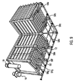
処理装置1は、5100mm×3800mmの据え付け面が要求されるように好ましく寸法付けされ得る。処理装置1は、本質的に、少なくとも又は正確に14m3までの浴槽容積を好ましく取り囲む。本発明に従う処理装置1の有効容積は、好ましくは3400mm×3000mm×1500mmの寸法を持ち、上端までのオーバーフローの高さは好ましくは200mmの寸法を持つ。
The
図5は、前述した本発明に従う処理装置1の別の角度からの斜視図である。この図から集約されるように、ノズル29a〜29c若しくは3×3のノズル列が、好ましくは有効領域に進入しないように若しくは悪影響を及ぼさないように、処理容器4の壁内のポケット61内に収容される。ノズル28a〜28bは、同様に、好ましくは有効領域に進入しないように若しくは悪影響を及ぼさないように、処理容器4の別の壁内のポケット内に収容される。ポケット61は、組み込んだ部品にダメージを与えないようにするために、保護用ラムを好ましく具備している。
FIG. 5 is a perspective view from another angle of the
さらに、追加のフィルタ装置19が設けられており、このフィルタ装置19は粗いフィルタとして好ましく設計される。調整されるべき処理物質は、特に好ましくは、まず、処理容器からサイフォン吸引され、それから、追加のフィルタ装置19に供給され、そして、ポンプ10を通ってガイドされ、それから、好ましくはバッグフィルタとして設計され得るフィルタ装置18を通ってガイドされ、そして、ノズル28,29を介して処理容器内に戻される。
Furthermore, an
図は、さらに、処理容器4の床が、水平に対して傾きをなした面部分53,54,55,56を見せていることを示している。この面部分53,54及び55,56は、垂直方向に見られる低い地点の領域において互いに直線的接触エリアを生ずるように、それぞれ、好ましく配列される。ここで、該接触エリアは、垂直方向に延びた該容器の外壁と各面部分つまり床部分53,54との間の接触エリアよりも下のレベルにおいて、好ましく横たわっている。従って、面部分つまり床部分53,54及び55,56は、処理物質及び汚染パーティクル(粒子、小片)を意図した手法で1以上の出口へとガイドする溝を好ましく形成する。面部分53〜56は、水平に対して、2度〜25度の傾きで、特に好ましくは2度〜25度の傾きで、最も好ましくは本質的に又は正確に10度の傾きで、好ましく整列される。
The figure further shows that the floor of the
参照番号8は、好ましく設けられた温度制御装置を示す。この温度制御装置8は、8個の電気的加熱要素を好ましく見せており、特にそれぞれが2キロワットである。これらの加熱要素は、同様に、好ましく要求された有効面に進入しないように若しくは悪影響を及ぼさないように、壁内のポケット61内に好ましく収容される。温度制御装置の加熱容量構成はウェスリング(Wessling)システムに好ましくは指向され得る(20m3=20キロワット容量)。
Reference numeral 8 indicates a temperature control device which is preferably provided. The temperature control device 8 preferably shows eight electrical heating elements, in particular each 2 kilowatts. These heating elements are likewise preferably housed in
特に、図6は、ポケット61の詳細図を示し、そこにおいてノズル29a〜29c及び温度制御装置8が好ましく配置されている。
In particular, FIG. 6 shows a detailed view of the
図7は、お互いに対して傾斜した処理容器の床部分53,54及び55,56によって形成された溝62の第1部分と、該溝の第2部分63とを示す。この溝は収集室14内にも延びている。出口57a〜57f、特に複数の該出口が、処理室から処理物質を排出又はサイフォン排出するために、該溝内に又は該溝の領域内に好ましく設けられる。さらに、収集室14内には、該収集室14から処理物質を排出又はサイフォン排出するための少なくとも1つの出口57gが好ましく設けられる。出口57a〜57gは接続ラインを介して主吸引ライン60に流体的に好ましく接続される。
FIG. 7 shows a first portion of a
図示しない格子が、好ましくは水平に整列され、若しくは処理容器4の側壁に直角に整列され、処理室の床53,54,55,56を覆うようになっており、ここで、この格子は該床から離隔し、特に20mm以上、好ましくは50mm以上、特に好ましくは100mm以上離隔しており、ここで、この格子は最大で500mmまで該床から離隔される。この格子は、処理室内に導入された処理されるべき対象物を、処理室の床から離す機能を好ましく果たし、その結果、該処理対象物から取り除かれたパーティクルが該処理対象物の下方にて堆積され得る。
A grid (not shown) is preferably aligned horizontally or at right angles to the side walls of the
図8は、主吸引ライン60と、前記出口57a〜57gを該主吸引ライン60に結合する接続パイプ58a〜58gの一部を示す。少なくとも接続パイプ58a〜58gと主吸引ライン60とで好ましく構成される全体的な吸引ラインは、分解できるように好ましく設計される。これは、特に、全体的な吸引ラインの個別部品を清掃するために有利である。
FIG. 8 shows a
図9は、本発明に従う処理装置1の下側の斜視図を示す。特に、出口と主吸引ラインに結合する接続パイプ58a〜58gがこの図から見出せる。
FIG. 9 shows a perspective view of the lower side of the
図10a及び10bは、図4乃至図9に示した本発明に従う処理装置1の様々な側面図を示す。
FIGS. 10a and 10b show various side views of the
本発明は、金属の処理対象物(2)のシングルステージ処理のための処理装置1に関し、該処理は前記処理対象物(2)を少なくとも酸洗及びリン酸塩処理することを包含し、該処理装置1は下記に述べる装置を少なくとも包含する。すなわち、処理されるべき対象物2を受理し且つ流動性の処理物質6を受理するための処理容器4と、該処理物質6の少なくとも一部を交換するためのポンプ装置10である。ここで、処理物質6は、前記処理されるべき対象物2の少なくとも一部分において、特には前記処理されるべき対象物2の全体において、その周囲を流れ、処理物質6は、リン又はリン酸塩を含有する溶液、特にリン酸であり、前記リン又はリン酸塩を含有する溶液は、部分的に水及び部分的に反応物質からなり、前記反応物質はリン又はリン酸塩及び追加的な処理効能改善物質からなり、前記反応物質中のリン又はリン酸塩の比率は少なくとも95%であり、前記反応物質は特に塩酸又は硫酸コンテンツを持たない。
The present invention relates to a
1 処理装置
2 処理対象物
4 処理容器
6 処理物質
8 温度制御装置
10 ポンプ装置
12 壁
14 収集室
16 移送ライン
18 フィルタ装置
19 追加のフィルタ装置
20 ダムの流れ
22 主受理室
24 第1の副受理室
26 第2の副受理室
27 グリッド
28 ノズル
39 ワイヤコイル
40 ワイヤ処理用の処理装置
41 分配ポイント
42 処理浴槽
43 固定浴槽
44 取り出しポイント
45 移送装置
46 圧力ベルトフィルタ装置
47 計量装置
48 完全に脱カルシウム化された水を調整する装置
49 制御装置
50 別の圧力ベルトフィルタ装置
51 貯蔵タンク
52 サイドチャンネルコンプレッサ
53 第1の傾斜した床部分
54 第2の傾斜した床部分
55 第3の傾斜した床部分
56 第4の傾斜した床部分
57 出口
58 接続パイプ
60 主吸引ライン
61 ノズル付きのポケット
62 溝の第1部分
63 溝の第2部分
DESCRIPTION OF
Claims (19)
前記処理対象物(2)を受理し且つ流動性の処理物質(6)を受理するための処理容器(4)と、
前記処理物質(6)の少なくとも一部を巡回するためのポンプ装置(10)と
を少なくとも具備し、
前記処理物質(6)は、前記処理対象物(2)の少なくとも一部分において、特に前記処理対象物(2)の全体において、その周囲を流れ、
前記処理物質(6)は、リン又はリン酸塩を含有する溶液、特にリン酸であり、
前記リン又はリン酸塩を含有する溶液は、部分的に水及び部分的に反応物質からなり、
前記反応物質はリン又はリン酸塩及び少なくとも1つの追加的な処理効能改善物質からなり、
前記反応物質中のリン又はリン酸塩の比率は少なくとも95%であり、
前記反応物質は特に塩酸又は硫酸コンテンツを含まない、
ことを特徴とする処理装置(1)。 A processing apparatus (1) for single stage processing of a metal processing object (2), the processing including at least pickling and phosphating the processing object (2),
A processing vessel (4) for receiving the processing object (2) and receiving a fluid processing substance (6);
And at least a pump device (10) for circulating at least a part of the treatment substance (6),
The treatment substance (6) flows around at least a part of the treatment object (2), particularly in the whole treatment object (2),
The treatment substance (6) is a solution containing phosphorus or phosphate, in particular phosphoric acid,
The phosphorus or phosphate-containing solution consists in part of water and part of the reactants;
The reactant comprises phosphorus or phosphate and at least one additional treatment efficacy improver,
The proportion of phosphorus or phosphate in the reactants is at least 95%;
The reactants do not contain any hydrochloric acid or sulfuric acid content,
The processing apparatus (1) characterized by the above-mentioned.
該完全に脱カルシウム化された水の部分に対する前記反応物質の部分の比は1:4乃至1:7の間であり、ここで、前記反応物質が前記完全に脱カルシウム化された水に混合される前は固体状態で存在しているならば、前記完全に脱カルシウム化された水の部分に対する前記反応物質の部分の比は好ましくは1:6を示し、
若しくは、前記反応物質が前記完全に脱カルシウム化された水に混合される前は液体状態で存在しているならば、前記完全に脱カルシウム化された水の部分に対する前記反応物質の部分の比は好ましくは1:5を示す、ことを特徴とする請求項1又は2の処理装置。 The solution containing phosphorus or phosphate consists of completely decalcified water and reactants, wherein the completely decalcified water consists in particular of VE water, and
The ratio of the reactant portion to the fully decalcified water portion is between 1: 4 and 1: 7, where the reactant is mixed into the fully decalcified water. If present in the solid state before being done, the ratio of the reactant portion to the fully decalcified water portion preferably exhibits 1: 6;
Or, if the reactant is present in a liquid state before being mixed with the fully decalcified water, the ratio of the portion of the reactant to the portion of the fully decalcified water. The processing device according to claim 1 or 2, characterized in that preferably represents 1: 5.
前記処理物質(6)をフィルタするためのフィルタ装置(18)が設けられていて、フィルタ処理によって該処理物質(6)内に累積された汚染物質を該処理物質(6)から除去し、
前記ポンプ装置(10)と前記フィルタ装置(18)が前記移送ライン(16)の一部を構成し、前記移送される処理物質(6)は前記ポンプ装置(10)によって前記フィルタ装置(18)を通して移送され、
前記移送ライン(16)は、前記処理容器(4)内に戻される前記処理物質(6)が該処理物質(6)の一部を前記処理容器(4)から前記収集室(14)内に排出するためにダムの流れ(20)を生成し得るように構成されている、ことを特徴とする請求項1乃至6のいずれかの処理装置。 The processing vessel (4) is partitioned by a wall (12) from a collection chamber (14) for collecting the processing substance (6) flowing over the wall (12), wherein the collection chamber The processing substance (6) collected in (14) can be transferred back into the processing container (4) via a transfer line (16),
A filter device (18) for filtering the treated substance (6) is provided, and contaminants accumulated in the treated substance (6) by the filtering process are removed from the treated substance (6),
The pump device (10) and the filter device (18) constitute a part of the transfer line (16), and the processing substance (6) to be transferred is transferred to the filter device (18) by the pump device (10). Transported through
In the transfer line (16), the processing substance (6) returned to the processing container (4) allows a part of the processing substance (6) to be transferred from the processing container (4) to the collection chamber (14). 7. A treatment device according to claim 1, wherein the treatment device is configured to generate a dam flow (20) for discharge.
ここで、該酸洗及び脱脂の添加物は、イオン化されていない水溶液、生分解性の表面活性剤、及び反応抑制物質、特に2−ブチン−1,4−ジオール、を好ましく提示し、
ここで、該酸洗及び脱脂の添加物は、前記リン又はリン酸塩を含有する溶液の体積の0.5%乃至7%、特に1%乃至5%の体積で追加される、ことを特徴とする請求項1乃至7のいずれかの処理装置。 Additional materials for pickling and degreasing are added to the treated material (6),
Here, the pickling and degreasing additive preferably presents a non-ionized aqueous solution, a biodegradable surfactant, and a reaction inhibitor, particularly 2-butyne-1,4-diol,
Here, the pickling and degreasing additives are added in a volume of 0.5% to 7%, particularly 1% to 5% of the volume of the solution containing phosphorus or phosphate. The processing apparatus according to claim 1.
ここで、該泡消しの添加物は、好ましくはトリイソブチル・リン酸塩を示し、該泡消し添加物は、前記リン又はリン酸塩を含有する溶液の体積の0.01%乃至5%、特に0.2%、の体積で前記処理物質(6)に追加されるか、
あるいは、前記酸洗及び脱脂の添加物で反応させられた前記リン又はリン酸塩を含有する溶液の体積の0.01%乃至5%、特に0.2%、の体積で前記処理物質(6)に追加される、ことを特徴とする請求項1乃至8のいずれかの処理装置。 An additional substance for defoaming is added to the treatment substance (6),
Here, the defoaming additive preferably represents triisobutyl phosphate, and the defoaming additive is 0.01% to 5% of the volume of the solution containing the phosphorus or phosphate, Is added to the treatment substance (6), in particular in a volume of 0.2%,
Alternatively, the treatment substance (6) in a volume of 0.01% to 5%, especially 0.2% of the volume of the solution containing phosphorus or phosphate reacted with the pickling and degreasing additive. The processing apparatus according to any one of claims 1 to 8, wherein
ここで、前記主受理室(22)は、第2の副受理室(26)にも結合されており、
前記第1の受理室(24)は、前記主受理室(22)の下側に好ましく形成されて特定の量の前記処理物質(6)を受理するためのバッファ受理室であり、
前記第2の副受理室(26)は、前記主受理室(22)の側部に対して好ましく形成された温度制御室であり、該第2の副受理室(26)内に温度制御装置(8)が少なくとも部分的に位置される、ことを特徴とする請求項1乃至9のいずれかの処理装置。 The processing container (4) includes a main receiving chamber (22) into which the processing object (2) can be introduced, and at least a first sub-receiving chamber (24), wherein the main receiving chamber (22) ) And the first sub-receiving chamber (24), the treatment substance (6) can flow out of the main receiving chamber (22) and into the first sub-receiving chamber (24). Thus, on the other hand, they are joined together so that they can flow out of the first sub-receiving chamber (24) and into the main receiving chamber (22), and the main receiving chamber (22) The first sub-receiving chamber (24) is partitioned from each other so that the object (2) does not enter the first sub-receiving chamber (24), at least partially, preferably completely. And
Here, the main receiving room (22) is also coupled to a second sub-receiving room (26),
The first receiving chamber (24) is a buffer receiving chamber that is preferably formed under the main receiving chamber (22) and receives a specific amount of the processing substance (6).
The second sub-receiving chamber (26) is a temperature control chamber that is preferably formed with respect to the side of the main receiving chamber (22), and a temperature control device is provided in the second sub-receiving chamber (26). 10. The processing device according to claim 1, wherein (8) is at least partially located.
該制御装置は、前記処理物質(6)に目標温度又は目標温度経過がもたらされるように温度制御装置(8)を制御し、及び/又は、
該制御装置は、前記処理物質(6)が目標流速又は目標流れ特性で移送されるようにポンプ装置(10)を制御し、及び/又は、
該制御装置は、前記処理物質(6)のフィルタされた部分が目標清浄度を示すようにフィルタ装置(18)を制御し、及び/又は、
該制御装置は、前記処理物質(6)の目標組成が設定されるように計量装置を制御する、ことを特徴とする請求項1乃至10のいずれかの処理装置。 A control device is provided,
The control device controls the temperature control device (8) such that a target temperature or a target temperature course is provided to the processing substance (6) and / or
The control device controls the pump device (10) so that the processing substance (6) is transferred at a target flow rate or target flow characteristic and / or
The control device controls the filter device (18) such that the filtered portion of the treatment substance (6) exhibits a target cleanliness and / or
11. The processing device according to claim 1, wherein the control device controls the measuring device so that a target composition of the processing substance (6) is set.
少なくとも1つの処理対象物(2)を受理し且つ流動性の処理物質(6)を受理するための処理容器(4)を提供するステップと、
前記処理物質(6)を前記処理容器(4)内に導入するステップと、ここで、追加の処理容器が酸洗及びリン酸塩処理するために使用されることがなく、
前記処理物質(6)で少なくとも部分的に満たされた前記処理容器(4)内に、前記処理対象物(2)を導入し、該処理対象物(2)に該処理物質(6)との接触をもたらすステップ、
を少なくとも含み、
前記処理物質(6)と前記処理対象物(2)との前記接触は、少なくともクリーニング、特に該処理対象物(2)の酸洗及びリン酸塩処理、を引き起し、
前記処理物質(6)は、リン又はリン酸塩を含有する溶液、特にリン酸であり、
前記リン又はリン酸塩を含有する溶液は、一方で水と他方で反応物質とからなり、
前記反応物質はリン又はリン酸塩及び少なくとも1つの追加的な処理効能改善物質からなり、
前記反応物質中のリン又はリン酸塩の比率は少なくとも95%であり、
前記反応物質は特に塩酸及び硫酸コンテンツを含まない、
ことを特徴とする処理方法。 In particular, it is a treatment method for at least pickling and phosphating a metal treatment object (2),
Providing a processing vessel (4) for receiving at least one processing object (2) and receiving a flowable processing substance (6);
Introducing the treatment substance (6) into the treatment vessel (4), wherein no additional treatment vessel is used for pickling and phosphating,
The treatment object (2) is introduced into the treatment container (4) at least partially filled with the treatment substance (6), and the treatment object (2) is mixed with the treatment substance (6). Steps that bring contact,
Including at least
The contact between the treatment substance (6) and the treatment object (2) causes at least cleaning, in particular pickling and phosphate treatment of the treatment object (2),
The treatment substance (6) is a solution containing phosphorus or phosphate, in particular phosphoric acid,
The solution containing phosphorus or phosphate consists of water on the one hand and reactants on the other hand,
The reactant comprises phosphorus or phosphate and at least one additional treatment efficacy improver,
The proportion of phosphorus or phosphate in the reactants is at least 95%;
The reactants are especially free of hydrochloric acid and sulfuric acid content,
A processing method characterized by the above.
ここで、該酸洗及び脱脂の添加物は、イオン化されていない水溶液、生分解性の表面活性剤、及び反応抑制物質、特に2−ブチン−1,4−ジオール、を好ましく提示し、
ここで、該酸洗及び脱脂の添加物は、前記リン又はリン酸塩を含有する溶液の体積の0.5%乃至7%、特に1%乃至5%の体積で追加される、請求項12の方法。 Adding an additional substance for pickling and degreasing to the treatment substance (6),
Here, the pickling and degreasing additive preferably presents a non-ionized aqueous solution, a biodegradable surfactant, and a reaction inhibitor, particularly 2-butyne-1,4-diol,
Here, the pickling and degreasing additives are added in a volume of 0.5% to 7%, in particular 1% to 5% of the volume of the solution containing phosphorus or phosphate. the method of.
ここで、該泡消しの添加物は、好ましくはトリイソブチル・リン酸塩を示し、
該泡消し添加物は、前記リン又はリン酸塩を含有する溶液の体積の0.01%乃至5%、特に0.2%、の体積で前記処理物質(6)に追加されるか、
あるいは、前記酸洗及び脱脂の添加物で反応させられた前記リン又はリン酸塩を含有する溶液の体積の0.01%乃至5%、特に0.2%、の体積で前記処理物質(6)に追加される、ことを特徴とする請求項12又は13の方法。 An additional substance for defoaming is added to the treatment substance (6),
Here, the defoaming additive preferably represents triisobutyl phosphate,
The defoaming additive is added to the treatment substance (6) in a volume of 0.01% to 5%, in particular 0.2% of the volume of the solution containing phosphorus or phosphate,
Alternatively, the treatment substance (6) in a volume of 0.01% to 5%, especially 0.2% of the volume of the solution containing phosphorus or phosphate reacted with the pickling and degreasing additive. 14. The method of claim 12 or 13, wherein:
該完全に脱カルシウム化された水の部分に対する前記反応物質の部分の比は1:4乃至1:7の間であり、ここで、前記反応物質が前記完全に脱カルシウム化された水に混合される前は固体状態で存在しているならば、前記完全に脱カルシウム化された水の部分に対する前記反応物質の部分の比は好ましくは1:6を示し、
若しくは、前記反応物質が前記完全に脱カルシウム化された水に混合される前は液体状態で存在しているならば、前記完全に脱カルシウム化された水の部分に対する前記反応物質の部分の比は好ましくは1:5を示す、ことを特徴とする請求項12乃至15のいずれかの方法。 The solution containing phosphorus or phosphate consists of completely decalcified water and reactants, wherein the completely decalcified water consists in particular of VE water, and
The ratio of the reactant portion to the fully decalcified water portion is between 1: 4 and 1: 7, where the reactant is mixed into the fully decalcified water. If present in the solid state before being done, the ratio of the reactant portion to the fully decalcified water portion preferably exhibits 1: 6;
Or, if the reactant is present in a liquid state before being mixed with the fully decalcified water, the ratio of the portion of the reactant to the portion of the fully decalcified water. 16. A method according to any of claims 12 to 15, characterized in that preferably represents 1: 5.
Applications Claiming Priority (3)
| Application Number | Priority Date | Filing Date | Title |
|---|---|---|---|
| DE102014006315.1 | 2014-04-30 | ||
| DE102014006315 | 2014-04-30 | ||
| PCT/EP2015/052326 WO2015165600A1 (en) | 2014-04-30 | 2015-02-04 | Treatment device and treatment method for pickling and phosphating metal parts |
Publications (1)
| Publication Number | Publication Date |
|---|---|
| JP2017514997A true JP2017514997A (en) | 2017-06-08 |
Family
ID=52446375
Family Applications (1)
| Application Number | Title | Priority Date | Filing Date |
|---|---|---|---|
| JP2016565183A Pending JP2017514997A (en) | 2014-04-30 | 2015-02-04 | Processing apparatus and processing method for pickling and phosphating metal parts |
Country Status (12)
| Country | Link |
|---|---|
| US (1) | US10513784B2 (en) |
| EP (1) | EP3137651B1 (en) |
| JP (1) | JP2017514997A (en) |
| KR (1) | KR20160149226A (en) |
| CN (1) | CN106460185B (en) |
| BR (1) | BR112016025403A2 (en) |
| CA (1) | CA2947370A1 (en) |
| CL (1) | CL2016002754A1 (en) |
| DE (1) | DE102015005521B4 (en) |
| MX (1) | MX2016014200A (en) |
| RU (1) | RU2691443C2 (en) |
| WO (1) | WO2015165600A1 (en) |
Cited By (1)
| Publication number | Priority date | Publication date | Assignee | Title |
|---|---|---|---|---|
| JP2019515133A (en) * | 2016-04-29 | 2019-06-06 | ケメタル ゲゼルシャフト ミット ベシュレンクテル ハフツング | Composition for reducing corrosion removal of material in pickling of metal surfaces comprising bare steel and / or galvanized steel |
Families Citing this family (7)
| Publication number | Priority date | Publication date | Assignee | Title |
|---|---|---|---|---|
| DE102015014323A1 (en) * | 2015-11-05 | 2017-05-11 | Retomax Ag | Treatment device for pickling and phosphating of metal parts and treatment methods and treatment plant for coating the metal parts |
| DE102015014322A1 (en) * | 2015-11-05 | 2017-05-11 | Retomax Ag | Treatment device for pickling and phosphating of metal parts and treatment method and treatment plant for galvanizing the metal parts |
| DE102015014304A1 (en) * | 2015-11-05 | 2017-05-11 | Retomax Ag | Treatment device for pickling and phosphating wire or wire parts and treatment method and treatment device for coating the wire or the wire parts |
| DE102017112736A1 (en) * | 2017-05-17 | 2018-11-22 | Schaeffler Technologies AG & Co. KG | Method for surface modification of at least one component and reactor device for carrying out the method |
| KR102290319B1 (en) | 2021-04-26 | 2021-08-19 | 신우이엔지 주식회사 | Picking apparatus |
| CN114457329A (en) * | 2022-03-05 | 2022-05-10 | 滁州职业技术学院 | Passivation liquid spray set |
| CN115142058B (en) * | 2022-09-01 | 2022-11-22 | 苏州千竹齿轮传动设备有限公司 | Phosphating device for gear rust-proof machining |
Citations (8)
| Publication number | Priority date | Publication date | Assignee | Title |
|---|---|---|---|---|
| US1949921A (en) * | 1932-07-01 | 1934-03-06 | Grasselli Chemical Co | Cleaning and protecting metals against rusting |
| GB647782A (en) * | 1946-07-12 | 1950-12-20 | Herbert Manfred Freud | Improvements in or relating to the degreasing, pickling and passivation of metals |
| JPS4928092B1 (en) * | 1968-01-23 | 1974-07-23 | ||
| JPS5662967A (en) * | 1979-10-24 | 1981-05-29 | Nippon Paint Co Ltd | Chemical conversion treatment of metal surface and its apparatus |
| US4381249A (en) * | 1979-05-14 | 1983-04-26 | Bouffard Joseph O | Rust removing and metal surface protecting composition |
| US6171409B1 (en) * | 1998-07-18 | 2001-01-09 | Henkel Kommanditgesellschaft Auf Aktien | Process for the chemical treatment of metal surfaces and installation suitable therefor |
| JP2002155375A (en) * | 2000-09-08 | 2002-05-31 | Asahi Kagaku Kogyo Co Ltd | Surface treatment agent for galvanized steel sheet having excellent corrosion resistance, treated steel sheet and method for treating steel sheet |
| JP2007182591A (en) * | 2005-12-30 | 2007-07-19 | Hiroshi Miyata | Derusting/antirusting agent and derusting method using the same |
Family Cites Families (47)
| Publication number | Priority date | Publication date | Assignee | Title |
|---|---|---|---|---|
| US2307928A (en) * | 1939-02-24 | 1943-01-12 | Hanson Van Winkle Munning Co | Process and apparatus for cleaning metal |
| US2322134A (en) * | 1939-09-29 | 1943-06-15 | Mellon Inst Of Ind Res | Process for recovery of by-products from waste pickle liquors |
| US2769735A (en) * | 1954-09-29 | 1956-11-06 | Cleveland Ind Res Inc | Method of pickling iron and recovering pickling agent |
| US3144361A (en) * | 1955-11-10 | 1964-08-11 | Klinghoffer Stefan | Pretreating iron or steel |
| US2890944A (en) * | 1956-05-25 | 1959-06-16 | North American Aviation Inc | Continuous chemical milling process |
| US3404079A (en) * | 1965-01-11 | 1968-10-01 | Ashland Oil Inc | Process for preparing an electrocoating bath |
| FR1442457A (en) * | 1965-04-29 | 1966-06-17 | Process for descaling and protecting against oxidation of hot-manufactured steel products and device allowing its implementation | |
| JPS4627933Y1 (en) | 1968-05-04 | 1971-09-28 | ||
| US3562016A (en) * | 1968-07-05 | 1971-02-09 | Lancy Lab | Continuous treatment of carry-over on ferrous metal workpieces |
| US3575711A (en) * | 1968-12-26 | 1971-04-20 | David Krofchak | Process for pickling and regenerating |
| JPS5131675B2 (en) | 1972-07-15 | 1976-09-08 | ||
| JPS5425500B2 (en) | 1972-11-22 | 1979-08-28 | ||
| JPS5133129A (en) | 1974-09-13 | 1976-03-22 | Mitsubishi Rayon Co | SUISEINETSUKO KASEIHIFUKU SOSEIBUTSU |
| SE441105B (en) | 1976-04-05 | 1985-09-09 | Amchem Prod | PROCEDURE FOR PREPARING AN AMORPH, LIGHT, HARD FIXED PHOSPHATE COATING |
| US4197139A (en) * | 1978-08-23 | 1980-04-08 | Hjersted Norman B | Process for the reclamation of acid from spent pickle liquor |
| US4298405A (en) | 1980-03-24 | 1981-11-03 | Intex Products, Inc. | Process for producing iron phosphate coatings at ambient temperature |
| JPS56158896A (en) | 1980-05-12 | 1981-12-07 | Toyota Motor Corp | Surface treating device |
| JPS5747880A (en) | 1980-09-02 | 1982-03-18 | Nittan Co Ltd | Treatment of chemically treating liquid containing sludge in chemical treatment with phosphate |
| DE3134231A1 (en) | 1981-08-29 | 1983-03-10 | Nippon Paint Co., Ltd., Osaka | Device for dip-phosphating of metal surfaces |
| JPS59197574A (en) | 1983-04-25 | 1984-11-09 | Mitsubishi Metal Corp | Formation of abrasion resistant surface |
| JPS6169976A (en) | 1984-09-12 | 1986-04-10 | Nippon Parkerizing Co Ltd | Method for controlling phosphate treating liquid |
| JPS62256971A (en) | 1986-04-30 | 1987-11-09 | Yamaha Motor Co Ltd | Chemical conversion treatment |
| DE3824063A1 (en) | 1988-07-15 | 1990-01-18 | Metallgesellschaft Ag | PROCESS FOR REDUCING THE CONDITION OF PHOSPHATING EQUIPMENT |
| JPH0375379A (en) | 1989-05-15 | 1991-03-29 | Nippon Paint Co Ltd | Coated product, production thereof, concentrated phosphating agent and concentrated treating agent for replenishment |
| JPH07100870B2 (en) * | 1990-04-24 | 1995-11-01 | 日本ペイント株式会社 | Method for treating zinc phosphate coating on metal surface |
| JP2739864B2 (en) * | 1991-05-01 | 1998-04-15 | 株式会社デンソー | Phosphate conversion treatment method |
| FR2686622B1 (en) | 1992-01-29 | 1995-02-24 | Francais Prod Ind Cfpi | CONCENTRATE FOR ACTIVATION AND REFINING BATH AND BATH OBTAINED FROM THIS CONCENTRATE. |
| JPH0589452U (en) | 1992-05-01 | 1993-12-07 | 住友金属工業株式会社 | Steel strip chemical conversion equipment |
| AT399727B (en) | 1993-06-07 | 1995-07-25 | Oekologia Beteiligungs Handels | OVERFLOW RESISTANT |
| JP2782655B2 (en) | 1993-06-30 | 1998-08-06 | 三菱自動車工業株式会社 | Chemical treatment method |
| GB2280123A (en) * | 1993-07-22 | 1995-01-25 | B Sa | Cleaning and phosphating ferrous workpieces in tanks having rotary impellers for liquid agitation |
| DE69406396T2 (en) * | 1993-11-30 | 1998-05-28 | Danieli Off Mecc | Process for returning material to be treated in surface treatments and finishing operations |
| JP3542207B2 (en) | 1995-10-13 | 2004-07-14 | 日本パーカライジング株式会社 | Aluminum-containing metal material surface treatment method |
| JPH1046376A (en) | 1996-08-06 | 1998-02-17 | Nippon Paint Plant Eng Kk | Basin for liquid treating process |
| DE19700326A1 (en) | 1997-01-08 | 1998-07-09 | Henkel Kgaa | Stabilizers for hydroxylamine in copper-containing phosphating solutions |
| US5931174A (en) * | 1997-06-16 | 1999-08-03 | Eaton Corporation | Apparatus and method for cleaning articles |
| DE19858035A1 (en) | 1998-07-18 | 2000-01-20 | Henkel Kgaa | Process for the chemical treatment of metal surfaces and suitable installation |
| US6235111B1 (en) * | 1998-11-25 | 2001-05-22 | Ez Environmental Solutions, Corporation | Closed-loop phosphatizing system and method |
| US6399517B2 (en) * | 1999-03-30 | 2002-06-04 | Tokyo Electron Limited | Etching method and etching apparatus |
| CA2413646C (en) | 2000-06-16 | 2013-02-12 | Brian B. Cuyler | Improved phosphating operation |
| DE10155976A1 (en) | 2001-11-14 | 2003-05-22 | Henkel Kgaa | Control of the accelerator concentration in phosphating baths |
| DE10160858A1 (en) | 2001-12-12 | 2003-07-03 | Henkel Kgaa | Chemically treating metal surfaces comprises contacting the metal surfaces with a solution of a process bath, in which the solution of the bath is circulated via a first line and a circulating pump |
| JP3869730B2 (en) * | 2002-01-16 | 2007-01-17 | 株式会社平間理化研究所 | Process liquid preparation and supply method and apparatus |
| US20040118483A1 (en) | 2002-12-24 | 2004-06-24 | Michael Deemer | Process and solution for providing a thin corrosion inhibiting coating on a metallic surface |
| JP2005089804A (en) | 2003-09-16 | 2005-04-07 | Kyodo Yushi Co Ltd | Tribology metal member used under hydrogen-containing environment, and lubricant |
| DE102008008781A1 (en) | 2008-02-12 | 2009-08-20 | Thyssenkrupp Electrical Steel Gmbh | Method for producing a grain-oriented electrical strip |
| DE102010032786A1 (en) | 2010-07-29 | 2012-02-02 | Basf Coatings Gmbh | Process for the corrosion-inhibiting coating of metal surfaces using phosphorus-containing low molecular weight compounds |
-
2015
- 2015-02-04 JP JP2016565183A patent/JP2017514997A/en active Pending
- 2015-02-04 MX MX2016014200A patent/MX2016014200A/en unknown
- 2015-02-04 CN CN201580022806.3A patent/CN106460185B/en not_active Expired - Fee Related
- 2015-02-04 CA CA2947370A patent/CA2947370A1/en not_active Abandoned
- 2015-02-04 US US15/307,957 patent/US10513784B2/en not_active Expired - Fee Related
- 2015-02-04 BR BR112016025403A patent/BR112016025403A2/en not_active Application Discontinuation
- 2015-02-04 RU RU2016146713A patent/RU2691443C2/en not_active IP Right Cessation
- 2015-02-04 KR KR1020167032136A patent/KR20160149226A/en not_active Application Discontinuation
- 2015-02-04 WO PCT/EP2015/052326 patent/WO2015165600A1/en active Application Filing
- 2015-02-04 EP EP15702495.1A patent/EP3137651B1/en not_active Not-in-force
- 2015-04-30 DE DE102015005521.6A patent/DE102015005521B4/en not_active Expired - Fee Related
-
2016
- 2016-10-28 CL CL2016002754A patent/CL2016002754A1/en unknown
Patent Citations (8)
| Publication number | Priority date | Publication date | Assignee | Title |
|---|---|---|---|---|
| US1949921A (en) * | 1932-07-01 | 1934-03-06 | Grasselli Chemical Co | Cleaning and protecting metals against rusting |
| GB647782A (en) * | 1946-07-12 | 1950-12-20 | Herbert Manfred Freud | Improvements in or relating to the degreasing, pickling and passivation of metals |
| JPS4928092B1 (en) * | 1968-01-23 | 1974-07-23 | ||
| US4381249A (en) * | 1979-05-14 | 1983-04-26 | Bouffard Joseph O | Rust removing and metal surface protecting composition |
| JPS5662967A (en) * | 1979-10-24 | 1981-05-29 | Nippon Paint Co Ltd | Chemical conversion treatment of metal surface and its apparatus |
| US6171409B1 (en) * | 1998-07-18 | 2001-01-09 | Henkel Kommanditgesellschaft Auf Aktien | Process for the chemical treatment of metal surfaces and installation suitable therefor |
| JP2002155375A (en) * | 2000-09-08 | 2002-05-31 | Asahi Kagaku Kogyo Co Ltd | Surface treatment agent for galvanized steel sheet having excellent corrosion resistance, treated steel sheet and method for treating steel sheet |
| JP2007182591A (en) * | 2005-12-30 | 2007-07-19 | Hiroshi Miyata | Derusting/antirusting agent and derusting method using the same |
Cited By (1)
| Publication number | Priority date | Publication date | Assignee | Title |
|---|---|---|---|---|
| JP2019515133A (en) * | 2016-04-29 | 2019-06-06 | ケメタル ゲゼルシャフト ミット ベシュレンクテル ハフツング | Composition for reducing corrosion removal of material in pickling of metal surfaces comprising bare steel and / or galvanized steel |
Also Published As
| Publication number | Publication date |
|---|---|
| US10513784B2 (en) | 2019-12-24 |
| CN106460185B (en) | 2020-02-21 |
| CL2016002754A1 (en) | 2017-02-03 |
| RU2016146713A (en) | 2018-05-30 |
| BR112016025403A2 (en) | 2017-08-15 |
| US20170051414A1 (en) | 2017-02-23 |
| DE102015005521B4 (en) | 2017-02-09 |
| KR20160149226A (en) | 2016-12-27 |
| EP3137651A1 (en) | 2017-03-08 |
| DE102015005521A1 (en) | 2015-11-05 |
| WO2015165600A1 (en) | 2015-11-05 |
| RU2016146713A3 (en) | 2018-10-26 |
| EP3137651B1 (en) | 2018-12-19 |
| MX2016014200A (en) | 2017-05-03 |
| CN106460185A (en) | 2017-02-22 |
| RU2691443C2 (en) | 2019-06-13 |
| CA2947370A1 (en) | 2015-11-05 |
Similar Documents
| Publication | Publication Date | Title |
|---|---|---|
| JP2017514997A (en) | Processing apparatus and processing method for pickling and phosphating metal parts | |
| CN108368611B (en) | Treatment device for pickling and phosphating of threads or thread parts, and treatment method and treatment installation for coating threads or thread parts | |
| CN101100755B (en) | Acid pickling method of copper pipe for automobile oil cooler | |
| CN108350576B (en) | Treatment device for the acidification and phosphating of metal parts | |
| CN1232627C (en) | Cleanning agent and preparing method, and application in cleaning without stopping engine | |
| JP5410201B2 (en) | Sulfuric acid bath for high current density Sn plating on copper alloy plate and Sn plating method | |
| JP2011162812A (en) | Method for pickling operation of stainless steel strip | |
| EP3371342B1 (en) | Treatment device for pickling and phosphating metal parts | |
| EP3371340B1 (en) | Treatment device comprising a swirling apparatus for pickling and phosphating metal parts | |
| JP2008248303A (en) | Pitting corrosion inhibitor for circulating cooling water system including copper base material, and method for inhibiting pitting corrosion | |
| CN112789369A (en) | Surface treating agent |
Legal Events
| Date | Code | Title | Description |
|---|---|---|---|
| A621 | Written request for application examination |
Free format text: JAPANESE INTERMEDIATE CODE: A621 Effective date: 20180112 |
|
| A977 | Report on retrieval |
Free format text: JAPANESE INTERMEDIATE CODE: A971007 Effective date: 20181116 |
|
| A131 | Notification of reasons for refusal |
Free format text: JAPANESE INTERMEDIATE CODE: A131 Effective date: 20181204 |
|
| A601 | Written request for extension of time |
Free format text: JAPANESE INTERMEDIATE CODE: A601 Effective date: 20190301 |
|
| A02 | Decision of refusal |
Free format text: JAPANESE INTERMEDIATE CODE: A02 Effective date: 20190730 |