JP2017190895A - Liquid draining device of base material - Google Patents
Liquid draining device of base material Download PDFInfo
- Publication number
- JP2017190895A JP2017190895A JP2016079704A JP2016079704A JP2017190895A JP 2017190895 A JP2017190895 A JP 2017190895A JP 2016079704 A JP2016079704 A JP 2016079704A JP 2016079704 A JP2016079704 A JP 2016079704A JP 2017190895 A JP2017190895 A JP 2017190895A
- Authority
- JP
- Japan
- Prior art keywords
- base material
- substrate
- gas injection
- support
- liquid
- Prior art date
- Legal status (The legal status is an assumption and is not a legal conclusion. Google has not performed a legal analysis and makes no representation as to the accuracy of the status listed.)
- Granted
Links
Images

Landscapes
- Cleaning In General (AREA)
- Drying Of Solid Materials (AREA)
Abstract
【課題】曲面形状を有する基材の洗浄後、確実に液切りして、洗浄痕の発生を防止できる基材の液切り装置を提供する。【解決手段】基材の液切り装置100は、少なくとも一部に曲面形状を有する基材Pを支持する基材支持部31と、気体を噴射する気体噴射部33と、基材支持部31と気体噴射部33とを相対移動させる相対移動機構とを備える。相対移動機構は、相対移動に伴う基材表面の法線方向の変化に応じて、気体噴射部33からの気体噴射方向と基材表面の法線方向とのなす吹き当て角θを調整する。【選択図】図2The present invention provides a liquid draining apparatus for a substrate that can reliably drain liquid after cleaning a substrate having a curved shape and prevent generation of cleaning marks. A base material draining apparatus includes a base material support part that supports a base material having at least a curved shape, a gas injection part that injects gas, and a base material support part. A relative movement mechanism that relatively moves the gas injection unit 33. The relative movement mechanism adjusts the blowing angle θ formed by the gas injection direction from the gas injection unit 33 and the normal direction of the substrate surface according to a change in the normal direction of the substrate surface accompanying the relative movement. [Selection] Figure 2
Description
本発明は、基材の液切り装置に関する。 The present invention relates to a substrate draining device.
ガラス材等からなる基材を、その表面にスクリーン印刷やパッド印刷等の各種の印刷方法により所望のパターンを印刷し、美観に優れた装飾用部品として使用することがある。基材表面を印刷する際、塵埃や微小な異物、或いは付着した油脂等を除去するため、予め洗浄液により基材表面を洗浄する必要がある。そして、基材表面の洗浄後は、圧縮空気を基材に吹き当てて基材表面に付着している処理液を除去する液切りが行われる。この液切り方法として、例えば特許文献1,2のような技術が知られている。 A base material made of a glass material or the like may be used as a decorative part having a beautiful appearance by printing a desired pattern on the surface by various printing methods such as screen printing and pad printing. When printing the surface of the substrate, it is necessary to clean the surface of the substrate with a cleaning liquid in advance in order to remove dust, minute foreign matter, or attached oil and fat. And after washing | cleaning of the base-material surface, the liquid draining which sprays compressed air on a base material and removes the processing liquid adhering to the base-material surface is performed. As this liquid draining method, for example, techniques such as Patent Documents 1 and 2 are known.
特許文献1の構成においては、処理液によって洗浄された基材を所定方向に搬送しながら、この基材の搬送方向と交差する方向に対して傾斜して配設されたエアーナイフから上記基材に気体を噴射することで、基材を乾燥させている。 In the configuration of Patent Document 1, the substrate cleaned from the processing liquid is conveyed in a predetermined direction, and the substrate is separated from an air knife disposed with an inclination with respect to a direction intersecting the conveyance direction of the substrate. The substrate is dried by injecting a gas into the substrate.
また、特許文献2の構成においては、基材の搬入方向に対し所定の角度で設置されたエアーナイフと、エアーナイフを上下動させる上下動手段と、を備え、基材の搬送位置を検出する位置検出センサの出力に応じてエアーナイフを上下させて、基材に対する気体の風圧を制御している。 Moreover, in the structure of patent document 2, it is equipped with the air knife installed at a predetermined angle with respect to the carrying-in direction of a base material, and the vertical movement means to move an air knife up and down, and detects the conveyance position of a base material The air knife is moved up and down in accordance with the output of the position detection sensor to control the wind pressure of the gas with respect to the substrate.
しかしながら、特許文献1の構成では、基材の被乾燥面が曲面形状、特に凹面形状であると、低い部分に処理液が溜まってしまい、気体の噴射量を増やしても処理液を除去しきれず、洗浄痕が残ってしまうおそれがある。また、特許文献2の構成も同様に、基材の乾燥面が曲面形状を有していると処理液を完全に除去できず、改善の余地があった。 However, in the configuration of Patent Document 1, if the surface to be dried has a curved shape, particularly a concave shape, the processing liquid is accumulated in a low portion, and the processing liquid cannot be removed even if the gas injection amount is increased. There is a risk that cleaning marks may remain. Similarly, in the configuration of Patent Document 2, if the dry surface of the substrate has a curved shape, the treatment liquid cannot be completely removed, and there is room for improvement.
また、基材を保持具で保持して搬送する場合、基材と保持具との接触部に処理液が残り易く、残存する処理液によって洗浄痕が生じてしまうおそれがある。 Further, when the substrate is transported while being held by a holder, the treatment liquid tends to remain at the contact portion between the substrate and the holder, and the remaining treatment liquid may cause cleaning marks.
本発明は、曲面形状を有する基材の洗浄後、確実に液切りして、洗浄痕の発生を防止できる基材の液切り装置を提供することを目的とする。 An object of the present invention is to provide a substrate draining device that can reliably drain liquid after washing a substrate having a curved surface shape and prevent the occurrence of washing marks.
本発明は、下記構成からなる。
少なくとも一部に曲面形状を有する基材に気体を吹き付けて、前記基材に付着している処理液を除去する基材の液切り装置であって、
前記基材を支持する基材支持部と、
気体を噴射する気体噴射部と、
前記基材支持部と前記気体噴射部とを相対移動させ、前記基材の一端部から他端部までの基材表面に前記気体噴射部からの気体噴流を吹き当てる相対移動機構と、
を備え、
前記相対移動機構は、吹き当て角調整部により前記相対移動に伴う前記基材表面の吹き当て位置における法線方向の変化に応じて、前記気体噴射部からの気体噴射方向と前記法線方向とのなす吹き当て角を調整する機能を有する基材の液切り装置。
The present invention has the following configuration.
A base material draining device that blows gas onto a base material having a curved surface at least partially to remove the treatment liquid adhering to the base material,
A substrate support part for supporting the substrate;
A gas injection unit for injecting gas;
A relative movement mechanism that relatively moves the base material support part and the gas injection part, and blows the gas jet from the gas injection part to the base material surface from one end part to the other end part of the base material;
With
The relative movement mechanism includes a gas injection direction from the gas injection unit and a normal direction according to a change in a normal direction at a spray position on the surface of the base material accompanying the relative movement by a spray angle adjusting unit. A substrate draining device having a function of adjusting the spray angle formed by the substrate.
本発明の基材の液切り装置によれば、曲面形状を有する基材の洗浄後、基材表面を確実に液切りでき、洗浄痕の発生を防止できる。 According to the substrate draining device of the present invention, the substrate surface can be reliably drained after cleaning the curved substrate, and the generation of cleaning marks can be prevented.
以下、本発明の実施形態について、図面を参照して詳細に説明する。
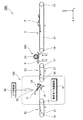
図1は基材の液切り装置が搭載された基材処理装置の模式図である。
基材処理装置200は、基材Pを洗浄処理して、乾燥処理する装置である。この基材処理装置200は、洗浄装置300、基材の液切り装置100、及び第1搬送部11、第2搬送部13、第3搬送部15を備える。以降、基材の液切り装置100を、液切り装置100と略称する。ここで用いる基材Pは、少なくとも一部に曲面形状を有するガラス材として説明する。基材Pは、無機ガラス、有機ガラスの他、種々の素材であってもよい。
Hereinafter, embodiments of the present invention will be described in detail with reference to the drawings.
FIG. 1 is a schematic diagram of a substrate processing apparatus equipped with a substrate liquid draining device.
The
第1搬送部11は、不図示の基材供給部から供給された基材Pを洗浄装置300に搬送する。第2搬送部13は、洗浄装置300から搬出された基材Pを液切り装置100に搬送する。第3搬送部15は、液切り装置100から搬出された基材Pを不図示の後段の処理部に向けて搬送する。
The
第1搬送部11、第2搬送部13、及び第3搬送部15は、搬送ベルト21が、駆動ローラ17及びガイドローラ19に巻き掛けられて走行するベルトコンベアとして構成される。この他にも、ローラコンベアによる搬送、ピッチ送り機構による搬送、カセット等の容器に基材Pを装填しての搬送等であってもよい。特に、ベルトコンベアやローラコンベアによれば、簡易で高効率に搬送できる。
The
各搬送部11,13,15は、少なくとも一部に曲面形状を有する基材Pであっても安定して搬送できる。より具体的な搬送方式としては、例えば、Vベルト等の断面が比較的小さい概略紐状の搬送ベルトを有するベルトコンベアを2台平行に配置して、基材Pの対向する2辺の端部を保持して搬送する方式であってもよい。又は、一定ピッチでの移動が可能なウォーキングビームに、基材Pの形状に合致した保持台を設置して、基材Pを保持台に載せながら搬送するピッチ送り機構による方式であってもよい。その場合、曲面形状を有する基材Pを効率的に搬送するには、基材Pを少なくとも3点で保持するのが望ましい。そこで、ピッチ送り機構による搬送では、基材Pの支持点を少なくとも3点設ける。更に、カセット等の容器に基材Pを装填して搬送する方式であってもよい。何れの方式であっても、後段の洗浄工程では洗浄水(処理液)を使用するため、搬送部には耐水性が求められる。上記した搬送部の構成によれば、曲面形状を持つ基材Pを回転させずに安定して搬送できる。
Each
洗浄装置300は、第1搬送部11と第2搬送部13との間に配置され、基材表面に洗浄液等の処理液を噴射供給して、回転ブラシ23を接触させて洗浄する。
The
液切り装置100は、第2搬送部13と第3搬送部15との間に配置され、気体噴射部であるエアーナイフ33から噴出する圧縮空気等の気体噴流を基材Pに吹き当てて、洗浄装置300で使用された処理液の残存液を液切りする。気体噴射部としては、一方向に気体噴流を噴射できればよく、ブロワーや波動ノズル等を用いることもできる。
The
上記構成の基材処理装置200は、第1搬送部11に搬入された基材Pを、第1搬送部11により洗浄装置300に搬送し、基材表面に処理液を噴射供給し、回転駆動される回転ブラシ23を基材表面に接触させて洗浄する。洗浄後の基材Pは、第2搬送部13により液切り装置100に搬送される。液切り装置100は、搬入された基材Pを、エアーナイフ33から噴射される圧縮空気によって液切りした後、第3搬送部15により次工程へ搬出する。
The base
ここで、液切り装置100について、詳細に説明する。
<液切り装置の構成>
液切り装置100は、基材Pに圧縮空気等の気体噴流を吹き当て、基材Pに付着している処理液を除去する。一般に、気体噴流による液切りは、比較的平坦な広い面の乾燥に利用され、効率的に処理できる。しかし、曲率が比較的大きい曲面形状を有する基材に対しては、気体噴流の基材表面への吹き当て位置と吹き当て角によっては、処理液を基材表面に残存させる可能性がある。そこで、本構成の液切り装置100は、気体噴流の基材表面への吹き当てにより、確実に液切りができるように基材Pを最適な姿勢に調整可能な構成としている。
Here, the liquid draining
<Configuration of liquid draining device>
The
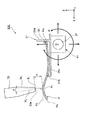
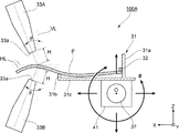
図2は基材の液切り装置の要部側面図である。
本構成の液切り装置100は、基材Pを支持する基材支持部31と、気体を噴射して気体噴流を生成するエアーナイフ33と、基材支持部31を移動させる移動ステージ41と、を備える。エアーナイフ33には、図1に示す圧縮空気等の気体を供給するエア供給部39が接続される。
FIG. 2 is a side view of an essential part of the substrate draining device.
The
基材支持部31は、基材Pの形状に適合したフレーム部材を有する。このフレーム部材は、基材Pを傾斜状態で支持させた場合でも基材Pを落下させずに支持する。フレーム部材は、基材係止部31a、31bと、これら基材係止部31a、31bを連結する連結部31cと、を有する。基材係止部31aは、フレーム部材上に載置された基材Pの搬送方向上流端である気体噴流の吹き当て終了端Pbに当接して、搬送方向前後の位置決めを行う。基材係止部31bは、吹き当て終了端Pbよりも気体噴流の吹き当て開始端Pa側の位置で基材Pを支持し、搬送方向に直交するY方向に位置決めする。なお、基材係止部31aには、基材Pの吹き当て終了端Pbを係止する引っ掛け部32が設けられている。
The base
基材支持部31による基材Pの支持方式は、基材Pを自重による摩擦で支持する支持方式の他、基材支持部31に吸着部を設けて基材Pを真空吸着する支持方式であってもよい。
The support method of the base material P by the base
本構成の液切り装置100は、エアーナイフ33が液切り装置100の不図示の固定部に固定される。また、基材支持部31が、相対移動機構である移動ステージ41に搭載され、移動ステージ41と共にエアーナイフ33に向けて移動する。これにより、基材支持部31とエアーナイフ33とが相対移動可能となっている。
In the
移動ステージ41は、基材支持部31を、搬送方向となるX軸方向、及び上下方向であるZ軸方向に移動自在に支持し、支持軸37の中心軸Oを中心とする回転方向φに回転自在に支持する。なお、移動ステージ41は、更にY軸方向に移動可能に構成されてもよい。その場合、より広いY方向幅の基材Pの液切りを実施できる。
The moving
上記構成の液切り装置100によれば、基材支持部31に支持される基材Pが、XZ面内の任意の位置へ移動可能となり、且つ、基材支持部31に支持された基材Pに対する気体噴流の吹き当て角θを、任意の角度に調整可能となる。
According to the
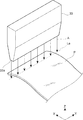
図3はエアーナイフ33から基材Pに向けて圧縮空気を噴射する様子を示すエアーナイフ33の模式的な斜視図である。
エアーナイフ33は、図1に示すエア供給部39に接続され、エア供給部39から供給される圧縮空気を気体噴射口33aから基材Pに向けて噴射する。気体噴射口33aは、エアーナイフ33の下部に設けられ、Y方向に沿った少なくとも一つのスリット状の開口を有する。また、気体噴射口33aの開口は、スリット状に限らず、複数の開口が均等ピッチで配置されたものであってもよい。
FIG. 3 is a schematic perspective view of the
The
上記構成のエアーナイフ33によれば、気体噴射口33aから噴出される圧縮空気が、図中矢印A方向で示す垂直下方に向けて吹き付けられる。よって、基材P上の吹き当て位置となる仮想線La上では、エアーナイフ33からの気体噴流が均等に吹き当てられる。
According to the
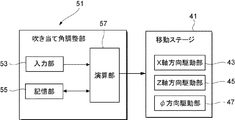
図4に液切り装置100の制御ブロック図を示す。
移動ステージ41は、基材支持部31をX軸方向へ駆動するX軸方向駆動部43と、Z軸方向へ駆動するZ軸方向駆動部45と、回転方向φに駆動するφ方向駆動部47とを有する。X軸方向駆動部43とZ軸方向駆動部45は、基材Pとエアーナイフ33とを水平方向及び垂直方向に移動させる直動駆動部として機能する。また、φ方向駆動部47は、基材支持部31とエアーナイフ33の少なくとも一方を他方に対して回転させる回転駆動部として機能する。
FIG. 4 shows a control block diagram of the
The moving
移動ステージ41は、吹き当て角調整部51から出力される駆動信号に基づいて駆動される。吹き当て角調整部51は、処理される基材Pの管理番号等を入力する入力部53と、複数の基材Pの大きさ、形状、素材等の基本情報を記憶する記憶部55と、演算部57と、を含んで構成される。演算部57は、エアーナイフ33と基材Pの目標位置に対応するX軸方向駆動信号、Z軸方向駆動信号、φ方向駆動信号を、それぞれX軸方向駆動部43、Z軸方向駆動部45、φ方向駆動部47に出力する。
The moving
これにより、吹き当て角調整部51は、図2に示すようにエアーナイフ33と基材支持部31との相対移動に伴う基材表面の法線方向NLの変化に応じて、エアーナイフ33からの気体噴流の噴射方向VLと基材表面の法線方向NLとのなす吹き当て角θを調整する。
As a result, the blowing
本構成の場合、エアーナイフ33が固定側となり、移動ステージ41が可動側となる。そのため、移動ステージ41により基材Pの姿勢を、X軸方向、Z軸方向、φ方向に調整しながら、基材表面に吹き当てられる気体噴流の位置と吹き当て方向とを最適にしつつ、基材PをX方向に搬送する。
In the case of this configuration, the
ここで、エアーナイフ33の気体噴射口33aから噴射される気体噴流の流速は、20m/s〜120m/sが好ましい。流速が20m/s以上であることにより、基材表面の処理液を吹き飛ばせる。また、流速が120m/s以下であることにより、基材Pが風圧により振動することなく、基材Pとエアーナイフ33との相対位置を一定の範囲に保ち、処理液を安定して吹き飛ばせる。
Here, the flow velocity of the gas jet injected from the
また、基材表面の法線方向NLとのなす角である気体噴流の吹き当て角θは、法線方向NLを0°とし、気体噴流吹き当て後の基材Pの吹き当て開始端Pa側を正の角度側、気体噴流吹き当て前の基材Pの配置側を負の角度側とすると、+30°〜+70°とすることが好ましい。吹き当て角θが上記範囲であると、エアーナイフ33の気体噴射口33aから噴射される気体噴流は、基材Pの吹き当て開始端Pa側から終了端Pbに向けて、残存する処理液を良好に除去できる。吹き当て角θが30°未満であると、基材表面の処理液が吹き当て開始端Pa側にも移動して、基材表面に残存させてしまうおそれがある。+70°を超えると、基材表面の処理液が終了端Pb側へ流れにくくなる。
Further, the blowing angle θ of the gas jet, which is an angle formed with the normal direction NL of the substrate surface, is 0 ° as the normal direction NL, and the blowing start end Pa side of the substrate P after the gas jet blowing Is the positive angle side, and the arrangement side of the base material P before the gas jet blowing is the negative angle side, it is preferable that the angle be + 30 ° to + 70 °. When the spray angle θ is within the above range, the gas jet injected from the
ここで、エアーナイフ33の気体噴射口33aから基材Pに向けて噴射される気体噴流の噴射方向VLの線上で、気体噴流が吹き当てられる基材Pの表面と交差する位置をPtとする。その場合、エアーナイフ33の気体噴射口33aの短辺中心E1から、基材Pの気体噴流の吹き当て位置Ptまでの距離Hは、基材P上の気体噴流の吹き当て位置によらず、常に設定した範囲に維持するのがよい。
Here, on the line of the jet direction VL of the gas jet jetted from the
距離Hは、上記した流速の範囲では、50〜200mmの範囲とすることが気体噴流の均一性が高められるため好ましい。距離Hが50mm未満であると、気体噴射口33a近傍の局所的に不均一となる流量の影響を受けムラが生じ、距離Hが200mmを超えると、十分な気体噴流の吹き当て強さが得にくくなる。
The distance H is preferably in the range of 50 to 200 mm in the above-described range of the flow velocity because the uniformity of the gas jet is enhanced. If the distance H is less than 50 mm, unevenness occurs due to the locally non-uniform flow rate in the vicinity of the
また、エアーナイフ33は、図示例のように単独で使用してもよく、複数個をY方向やX方向に並べて使用しても良い。例えば、一対のエアーナイフ33を、噴射方向VLが基材Pの搬送方向に関して互いに逆向きになるように、ハの字状に配置してもよい。これにより基材Pの中心から基材Pの端面方向に処理液を流せ、効率的に乾燥できる。また、エアーナイフ33の気体噴射口33aが上面視においてY軸とは平行とならないように配置してもよい。更に、供給する圧縮空気を温風としても良い。
Moreover, the
上記構成の液切り装置100によれば、吹き当て角調整部51の演算部57が、入力部53から入力された基材Pの管理番号に対応して記憶部55に記憶されている基本情報を参照し、X軸方向駆動部43を駆動する。また、演算部57は、Z軸方向駆動部45をZ方向に移動させて、エアーナイフ33の気体噴射口33aと基材Pとの距離を予め定めた設定した範囲の距離Hに維持する。更に、演算部57は、φ方向駆動部47を駆動して、基材支持部31を支持軸37の中心軸Oを中心に回転させて、気体噴流の噴射方向VLと、気体噴流の基材Pへの吹き当て位置における基材表面の法線方向NLとのなす吹き当て角θを、前述の角度範囲に維持する。
According to the
次に、本構成の基材の液切り装置100の液切り工程の手順を説明する。
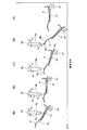
図5(A)〜(E)は基材支持部に支持される基材が、エアーナイフ33に対して相対移動しながら搬送されて基材表面に付着する処理液を液切りする工程を段階的に示す基材支持部の動作説明図である。
Next, the procedure of the liquid draining process of the base material
FIGS. 5A to 5E show a step in which the base material supported by the base material support portion is transported while moving relative to the
まず、図5(A)に示すように、基材支持部31に支持された基材Pは、移動ステージ41によってエアーナイフ33の直下に向けて搬送される。
First, as shown in FIG. 5A, the base material P supported by the base
そして、図5(B)に示すように、基材Pの吹き当て開始端Paを、エアーナイフ33直下における、気体噴射口33aと吹き当て開始端Paとの距離Hを設定した範囲の高さに配置する。また、エアーナイフ33からの気体噴流の噴射方向VLと、基材P上の気体噴流の吹き当て位置における法線方向NLと、のなす吹き当て角θを、前述した角度範囲にする。これにより、エアーナイフ33からの気体噴流に対する基材Pの吹き当て姿勢が調整される。
And as shown in FIG.5 (B), the height of the range which set the distance H of the spraying start end Pa of the base material P directly under the
吹き当て姿勢を調整する際、φ方向駆動部47の駆動による基材Pの回転によって、基材Pの吹き当て開始端PaのXZ面内における位置が変化する。この基材Pの回転によるX軸方向、及びZ軸方向のずれは、演算部57により予め求められる。演算部57は、回転によるX軸方向、Z軸方向のずれ量を加味して、移動ステージ41にX方向、Z方向、φ方向の目標座標を求め、この目標座標へ移動させる駆動信号を生成する。
When adjusting the spraying attitude, the position of the spraying start end Pa of the base material P in the XZ plane is changed by the rotation of the base material P driven by the φ-
図5(B)に示すように、エアーナイフ33からの気体噴流が、基材Pの吹き当て開始端Paに吹き当てられ、洗浄工程で基材表面に付着した洗浄水等の処理液が基材Pの吹き当て終了端Pbに向けて吹き飛ばされる。
As shown in FIG. 5B, the gas jet flow from the
そして、図5(C)、(D)、(E)に示すように、移動ステージ41は、演算部57からの駆動信号に基づいて、エアーナイフ33の気体噴射口から基材Pの噴射気体の吹き当て位置までの距離Hを設定した範囲に維持したまま、且つ気体噴流の吹き当て角θを前述した角度範囲に設定しながら、基材PをX方向に搬送する。
Then, as shown in FIGS. 5C, 5 </ b> D, and 5 </ b> E, the moving
上記の気体噴流の吹き当てによって、基材表面に残存する処理液が吹き飛ばされ、液切りされる。エアーナイフ33の気体噴射口33aから噴射される気体噴流は、常に基材Pの吹き当て開始端Pa側から終了端Pb側に向けて吹き当てられるので、処理液が確実に吹き飛ばされ、曲面形状を有する基材Pの凹部に溜まることがない。また、エアーナイフ33の気体噴射口33aと基材Pとの距離Hが設定した範囲に維持されるので、基材Pの全面に亘って均等に気体噴流が吹き当てられ、ムラなく液切りできる。なお、上記所定の範囲とは、設定した距離Hから±20mmの範囲を意味する。上記の液切り工程は1回に限らず、複数回実施してもよい。また、気体噴射口33aは、長方形状である他、正面視で曲線形状であってもよい。
The treatment liquid remaining on the surface of the base material is blown off by the blowing of the gas jet, and the liquid is drained. Since the gas jet jetted from the
液切り工程が完了した基材Pは、第3搬送部15へ移載されて次工程へ運搬される。液切り後の基材Pを運搬する第3搬送部15は、乾燥状態である必要があるため、搬送方向上流側の第2搬送部13とは分離されているのが望ましい。
The base material P for which the liquid draining process is completed is transferred to the
以上説明した本構成の基材の液切り装置100は、少なくとも一部に曲面形状を有する基材Pを支持する基材支持部31と、気体を噴射するエアーナイフ33と、基材支持部31とエアーナイフ33とを相対移動させ、基材Pの一端部から他端部までの基材表面にエアーナイフ33からの気体噴流を吹き当てる移動ステージ41とを備える。移動ステージ41は、基材Pとエアーナイフ33とを水平方向及び垂直方向に相対移動させる直動駆動部と、基材支持部31とエアーナイフ33の少なくとも一方を他方に対して回転させる回転駆動部を有して構成される。そして、相対移動に伴う基材表面の法線方向の変化に応じて、エアーナイフ33からの気体噴射方向と基材表面の法線方向とのなす吹き当て角を調整する吹き当て角調整部51を備える。
The base
この液切り装置100によれば、曲面形状を有する基材Pであっても、洗浄後の基材Pを、吹き当て姿勢を随時調整しながら搬送するので、基材Pの凹部等に処理液を残さず、確実に液切りでき、洗浄痕を残さずに乾燥できる。なお、基材Pの曲率は、曲率半径で50〜10000mmであり、100〜5000mmが好ましく、1000〜3000mmがより好ましい。
According to the
移動ステージ41は、固定されたエアーナイフ33に対して基材支持部31を移動させる構成であるため、エアーナイフ33と比較して軽量な基材支持部31の姿勢を変更する機構で済み、液切り装置100の機構を簡素化でき、基材Pの姿勢変更の自由度を高められる。また、エアーナイフ33を基材Pの形状にしたがって移動させる際に、エアーナイフ33と搬送部等の周辺の設備との干渉による制約を少なくできる。
Since the moving
また、吹き当て角調整部51は、エアーナイフ33からの気体噴流を、基材Pの吹き当て開始端Paから終了端Pbに向けて吹き当てるので、吹き当て後の基材表面の液残りを確実に防止できる。
Moreover, since the spray
更に、吹き当て角調整部51は、エアーナイフ33の気体噴射口33aから基材Pの気体噴流の吹き当て位置までの距離を設定した範囲になるよう調整するので、気体噴射口33aからの気体噴流を基材Pへ均等に吹き当て可能となり、基材Pの全面に亘ってムラなく液切りできる。
Furthermore, since the blowing
そして、表面が滑らかで洗浄痕が目立つガラス材であっても、確実な液切りが実施でき、良好な乾燥表面が得られる And even if it is a glass material with a smooth surface and conspicuous cleaning marks, reliable liquid draining can be performed and a good dry surface can be obtained
<第2構成例>
次に、基材の液切り装置の第2構成例を説明する。
図6は第2構成例の液切り装置の要部側面図である。本構成の液切り装置100Aは、エアーナイフ33A、33Bが基材Pの上面側と下面側とに合計一対設けられている。その他は、図2に示す液切り装置100と同様である。以降の説明では、同一の部材や部分に対しては同一の符号を付与して、その説明を簡略化又は省略する。
<Second configuration example>
Next, a second configuration example of the base material draining device will be described.
FIG. 6 is a side view of an essential part of the liquid draining device of the second configuration example. In the
本構成の液切り装置100Aは、基材支持部31の上面側にエアーナイフ33Aが配置され、下面側にエアーナイフ33Bが配置される。各エアーナイフ33A,33Bの気体噴流の吹き当て条件は、表裏面で基本的には同一にし、前述した通りの流速で、距離Hや吹き当て角θを所定の範囲に設定する。なお、表裏面における気体噴流の吹き当て条件は、表裏面のそれぞれで液切りが達成できればよく、互いに異なっていてもよい。
In the
この液切り装置100Aによれば、基材支持部31の上方及び下方にそれぞれエアーナイフ33A,33Bが配置されるので、基材Pの表裏両面に気体噴流が同時に吹き当てられ、基材Pの各表面に付着する処理液が同時に吹き飛ばされる。これにより、基材Pの表裏面の液切りが一度にでき、生産効率が向上する。
According to the
<第3構成例>
次に、基材の液切り装置の第3構成例を説明する。
基材の液切り後に処理液が基材表面に残存すると、最終的に処理液が残存した基材表面に汚れが形成される。この処理液の残存は、乾燥中の基材Pの保持方法に起因して発生することがある。例えば、気体噴流による液切りの場合、コンベア等の搬送装置と接触している部分には処理液が残り、これが汚れの原因となる場合がある。搬送方法としてローラコンベアを使用する場合は、ローラの配置間隔を拡げ、基材Pと搬送装置との接触を避けて処理液が残る問題を解決できるが、この方法では、概略平坦な基材Pに限定される。曲率の大きな曲面を有する基材Pには、搬送装置から基材Pを安定して保持可能な支持具へ基材Pを移載して乾燥し、乾燥完了後に搬送装置へ再度移載するのがよい。
<Third configuration example>
Next, the 3rd structural example of the liquid draining apparatus of a base material is demonstrated.
When the treatment liquid remains on the substrate surface after the substrate is drained, dirt is finally formed on the substrate surface where the treatment liquid remains. The remaining of the treatment liquid may occur due to a method of holding the substrate P during drying. For example, in the case of liquid cutting by a gas jet, the processing liquid remains in a portion that is in contact with a conveying device such as a conveyor, which may cause dirt. When a roller conveyor is used as a conveying method, the arrangement interval of rollers can be widened to solve the problem that the processing liquid remains by avoiding contact between the substrate P and the conveying device. However, in this method, the substantially flat substrate P It is limited to. For the base material P having a curved surface with a large curvature, the base material P is transferred from the transport device to a support that can stably hold the base material P, dried, and transferred again to the transport device after the drying is completed. Is good.
上記のような支持具への移載を行う具体的な基材支持部の構成例を以下に説明する。
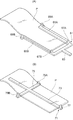
図7(A)は第3構成例の基材支持部である第1支持具の斜視図、(B)は第3構成例の基材支持部である第2支持具の斜視図である。
第1支持具61は、図7(A)に示すように、基材Pの搬送方向上流側に設けられる第1ロッド63と、第1ロッド63の基端とは反対の先端から二股に分岐して搬送方向下流側に向けて延設された一対の第2ロッド65A,65Bとを有する。一対の第2ロッド65A,65Bは、基材Pの搬送方向上流側の端部に当接する一対の基材係止部67A,67Bと、基材Pの搬送方向に直交する端部に当接する一対の基材係止部69A,69Bと、を有する。
A specific configuration example of the base material support portion for transferring to the support as described above will be described below.
FIG. 7A is a perspective view of a first support that is a base material support portion of the third configuration example, and FIG. 7B is a perspective view of a second support tool that is a base material support portion of the third configuration example.
As shown in FIG. 7A, the
基材係止部69Aは第2ロッド65Aの先端部に上方に突出して設けられ、基材係止部69Bは第2ロッド65Bの先端部に上方に突出して設けられる。基材係止部67A,67Bは、第2ロッド65A、65Bの第1ロッド63との接続部側にそれぞれ上方に突出して設けられる。
The base
第2支持具71は、図7(B)に示すように、搬送方向下流側から上流側に向けて延びる第1ロッド73と、第1ロッド73の長手方向の途中で、十字に交差して接続される第2ロッド75とを有する。
As shown in FIG. 7B, the
第1ロッド73は、搬送方向上流側の先端部に、基材Pの搬送方向上流側の端部に当接する基材係止部77を有する。また、第2ロッド75は、それぞれの先端部に、基材Pの搬送方向に直交する端部に当接する基材係止部79A,79Bを有する。
The
第1支持具61の基材係止部67A,67B,69A,69Bと、第2支持具71の基材係止部77,79A,79Bは、基材Pに対してそれぞれ異なる位置に配置される。また、基材Pの第1支持具61の第1ロッド63及び一対の第2ロッド65A,65Bと、第2支持具71の第1ロッド73及び第2ロッド75とは、上下方向に重ねた場合に、相互に干渉しないようになっている。
The base
上記構成の支持具によれば、第1支持具61により支持された基材Pは、第2支持具71が第1支持具61の下方から上昇して基材係止部77が基材係止部67A,67Bとの間に挿入される。また、基材係止部79A,79Bが基材Pの端部を挟み込む。次いで、第1支持具61を下降させると、第1支持具61の基材係止部67A,67B,69A,69Bの基材Pとの係合が外れ、基材Pが第2支持具71のみに支持される。
According to the support tool configured as described above, the base material P supported by the
つまり、第1支持具61と第2支持具71とを昇降駆動する図示しない持ち替え機構を駆動することにより、第1支持具61により支持された基材Pを、第1支持具61から第2支持具71に持ち替えできる。
That is, by driving a holding mechanism (not shown) that drives the
基材支持部を、上記の第1支持具61、第2支持具71、及び持ち替え機構を用いて構成することで、液切り効果を更に高められる。即ち、洗浄装置から搬送されてきた基材Pを最初に第1支持具61により支持させる。そして、第1支持具61により支持された基材Pを前述した気体噴流を吹き当てることで処理液を除去する。しかし、このときの第1支持具61の基材係止部67A,67B,69A,69Bと基材Pとの接触部分には、気体噴流が到達し難く、処理液が残ることがある。そこで、第1支持具61に支持された基材Pを第2支持具71に持ち替え、前述した気体噴流を吹き当てる。第2支持具71は、待機時においても処理液と触れておらず、常に乾燥した状態に保持されている。そのため、処理液を除去した後の第1支持具61から基材Pを持ち替えることにより、第1支持具61の各基材係止部67A,67B,69A,69Bに残存していた処理液は除去され、基材Pの全面を確実に液切りできる。また、上記の残存していた処理液は、各基材係止部67A,67B,69A,69Bの吹き当て方向下流側で堰き止められることがなく、基材P上に残存することがない。
By configuring the base material support portion using the
上記のように、気体噴流の吹き当てが、基材Pの搬送方向下流側から上流側に向けた一方向に行う場合、第2支持具71の基材係止部79A,79Bは、第1支持具の基材係止部69A,69Bよりも搬送方向下流側、即ち、噴流の上流側に配置されることが望ましい。これによれば、基材係止部69A,69Bに残存した処理液が、持ち替え後に基材係止部79A,79Bに流れ着くことなく、処理液の液残りを確実に防止できる。
As described above, when the blowing of the gas jet is performed in one direction from the downstream side in the conveyance direction of the base material P toward the upstream side, the base
<第4構成例>
次に、基材の液切り装置の第4構成例を説明する。
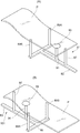
図8(A)は第4構成例の基材支持部である第1支持具の斜視図、(B)は第4構成例の基材支持部である第2支持具の斜視図である。本構成の基材支持部は、基材を吸着支持する吸着部を備え、第1支持具と第2支持具とが上下方向に重なることなく配置される点で前述の第3構成例の基材支持部とは異なっている。
<Fourth configuration example>
Next, a fourth configuration example of the base material draining device will be described.
FIG. 8A is a perspective view of a first support that is a base material support portion of the fourth configuration example, and FIG. 8B is a perspective view of a second support tool that is a base material support portion of the fourth configuration example. The base material support portion of this configuration includes an adsorbing portion that adsorbs and supports the base material, and the first support device and the second support device are arranged without overlapping in the vertical direction. It is different from the material support.
第1支持具81は、図8(A)に示すように、基端側となる基材Pの搬送方向上流側から下流側に向けて延びる第1ロッド83と、搬送方向と直交する方向に延びる第2ロッド85とが、第1ロッド83の基端とは反対の先端にT字型に接続される。
As shown in FIG. 8A, the
第1ロッド83は、上方に突出して頂部が基材Pに当接する突起部87を有し、第2ロッド85は、その両端部に突起部87と同様の一対の突起部89A,89Bを有する。また、第1ロッド83には、突起部91が立設され、その頂部には、基材Pを吸着保持する吸着部93が設けられている。この吸着部93は、基材Pの吸着状態で各突起部87,89A,89Bと基材Pとの間に垂直抗力を発生させて、基材Pを第1支持具81に着脱自在に固定させる。この吸着部93は、例えば、真空ポンプ等の吸引機構と、大気圧開放用のバルブとを備え、基材Pを着脱自在に支持する。また、吸着部93の吸着方式はこれに限らない。
The
第2支持具101は、図8(B)に示すように、図8(A)に示す第1支持具81とほぼ同一形状の部材であり、180°旋回した状態で使用される。第1支持具81は基材Pの搬送方向上流側を支持し、第2支持具101は基材Pの搬送方向下流側を支持する。なお、第1支持具81と第2支持具101の各突起部87,89A,89Bの先端は、ゴム等の柔軟な部材により覆われていてもよい。
As shown in FIG. 8 (B), the
第1支持具81と第2支持具101は、それぞれ基材Pの異なる位置を支持するため、液残りの発生を防止できる。また、第1支持具81、第2支持具101は、基材Pを吸着支持する構成であるので、必要に応じて基材Pを裏返すことも可能となり、基材Pの姿勢変更を容易に実施できる。
Since the
<相対移動機構の他の例>
以上説明した各構成の液切り装置は、相対移動機構として移動ステージ41を備え、固定されたエアーナイフ33に向けて移動ステージ41が移動する構成であるが、これに限らない。
<Other examples of relative movement mechanism>
The liquid draining device having each configuration described above includes the moving
図9は、基材支持部31に固定支持される基材Pに対して、エアーナイフ33が移動可能に配設された液切り装置100Bの要部側面図である。本構成の液切り装置100Bは、基材支持部31が固定され、この基材支持部31に支持される基材Pに対してエアーナイフ33がY軸と平行な線を中心に回転しつつX、Z方向に移動する。このとき、エアーナイフ33は、基材Pの吹き当て位置からの距離Hを、設定した範囲に維持しながら移動する。また、エアーナイフ33は、気体噴流の噴射方向VLと、基材P上の吹き当て位置における法線方向NLと、の吹き当て角θを、前述した所定範囲に維持しながら気体噴流を基材Pに向けて噴射する。
FIG. 9 is a side view of a main part of a
また、基材支持部31をX軸方向とZ軸方向に移動させ、エアーナイフ33を前述のφ方向に回転させる構成にしてもよい。
Alternatively, the
本構成の液切り装置100Bによれば、エアーナイフ33を固定せず、移動可能、回転可動に支持することで、基材支持部31の動作を単純にでき、基材支持部31を駆動する移動ステージの構造を簡素化できる。
According to the
<乾燥処理の他の例>
上記説明では、気体噴射部からの気体噴流による基材Pの液切りについて説明したが、液切りによる乾燥処理は、これに限らない。例えば、水分が気化するのに充分な温度に加温した空気を基材Pに当てて、基材P表面の水分の蒸発を促進する温風乾燥や、表面の水分を揮発性の高い液体に置換して蒸発を促進する置換乾燥等も適用でき、基材Pの形状や表面の性状によって適宜、選択される。
<Other examples of drying treatment>
In the above description, the liquid drainage of the base material P by the gas jet from the gas ejection unit has been described, but the drying process by the liquid drainage is not limited to this. For example, air heated to a temperature sufficient to evaporate moisture is applied to the substrate P, hot air drying that promotes evaporation of moisture on the surface of the substrate P, or surface moisture to a highly volatile liquid Substitution drying or the like that promotes evaporation by substitution can also be applied, and is appropriately selected depending on the shape of the substrate P and the surface properties.
温風乾燥では、例えば、基材支持部の上に置いた基材Pの周囲に、30〜100℃に加熱した空気流を定常的に流して、水分の蒸発を促進しながら乾燥処理を実施する。空気流を加温すれば、水分の乾燥がより促進される。更に、気体噴射部からの噴流を加温した温風とすることで、更に効率的な乾燥を実現できる。 In hot air drying, for example, an air flow heated to 30 to 100 ° C. is steadily flowed around the base material P placed on the base material support portion, and drying treatment is performed while promoting evaporation of moisture. To do. If the air flow is heated, moisture drying is further promoted. Furthermore, more efficient drying is realizable by making the warm air which heated the jet from a gas injection part.
<基材処理装置の洗浄工程の詳細>
次に、図1に示す基材処理装置200で実施する洗浄工程について説明する。
(洗浄工程)
図1に示すように、基材Pの洗浄工程は、基材Pを搬送手段の上で位置決めした後、基材Pの形状に合致した保持台に移載して、基材Pを保持台上で固定した状態で実施する。基材Pの搬送手段への投入作業は、搬送手段を停止させ、基材Pを1枚ずつ主要な洗浄面を上にして搬送手段の上に載置する。
<Details of cleaning process of substrate processing apparatus>
Next, the cleaning process performed by the
(Washing process)
As shown in FIG. 1, in the cleaning process of the base material P, after positioning the base material P on the conveying means, the base material P is transferred to a holding base that matches the shape of the base material P, and the base material P is transferred to the holding base. Carry out with the above fixed. In the operation of loading the base material P into the transport means, the transport means is stopped and the base materials P are placed on the transport means one by one with the main cleaning surface facing upward.
基材Pの洗浄方法としては、基材Pの洗浄面に平行な軸を持つ回転ブラシ23によるブラシ洗浄や、基材Pの洗浄面に概略垂直な回転軸を持つ回転パッドによるパッド洗浄、噴射水による噴水洗浄、超音波を利用した超音波洗浄等がある。これら各種の洗浄方法は、基材Pの形状や洗浄すべき汚れの種類によって適宜選択される。
As a cleaning method for the substrate P, brush cleaning with a rotating
ブラシ洗浄は、比較的平坦な広い面の洗浄に適し、また、比較的厚い汚れの除去に適する。パッド洗浄は、比較的急な面(曲率が大きい面)の洗浄まで適用でき、比較的厚い汚れの除去に適する。噴水洗浄は、曲率が大きい面の洗浄までできるが、固着力の弱い水溶性の汚れの除去に適する。超音波洗浄は、曲率が大きい面の洗浄まで適用できるが、非常に薄い汚れ層の除去に適する。 Brush cleaning is suitable for cleaning a relatively flat and wide surface, and for removing relatively thick dirt. The pad cleaning can be applied up to cleaning of a relatively steep surface (surface having a large curvature), and is suitable for removing a relatively thick stain. Fountain cleaning can be performed even on surfaces with a large curvature, but is suitable for removing water-soluble soils with weak adhesion. Ultrasonic cleaning can be applied to cleaning a surface with a large curvature, but is suitable for removing a very thin dirt layer.
ブラシ洗浄やパッド洗浄では、保持台に固定された基材Pに洗浄水が供給され、洗浄水を供給しながらブラシやパッドを回転させて基材Pに接触させる。この動作により、基材P表面のキズの発生を抑制すると共に除去した汚れを連続して排出できる。また、洗浄水には、必要に応じて洗浄剤や研磨材を加えてもよい。その場合、洗浄後に洗浄剤や研磨剤を除去するためのリンス処理を実施する。 In brush cleaning or pad cleaning, cleaning water is supplied to the substrate P fixed to the holding table, and the brush or pad is rotated while the cleaning water is being supplied to contact the substrate P. By this operation, the generation of scratches on the surface of the base material P can be suppressed and the removed dirt can be continuously discharged. Further, a cleaning agent or an abrasive may be added to the cleaning water as necessary. In that case, a rinsing process for removing the cleaning agent and the abrasive is performed after the cleaning.
洗浄で使用する洗浄水としては、精密フィルタでろ過処理を施した純水や、イオン交換膜で処理を施したRO水が使用される。洗浄水は、達成すべき洗浄度に応じて選択され、例えば、より高い洗浄度が求められる場合には純水を使用する。また、洗浄水を30℃〜70℃に加温すれば洗浄能力がより高められる。 As washing water used for washing, pure water filtered with a precision filter or RO water treated with an ion exchange membrane is used. The washing water is selected according to the degree of washing to be achieved. For example, when a higher degree of washing is required, pure water is used. Further, if the washing water is heated to 30 ° C. to 70 ° C., the washing ability is further enhanced.
また、洗浄で使用される洗浄剤としては、アニオン系界面活性剤などの中性洗剤が使用される。なお、これらは例として挙げたものであり、その他、種々の洗浄材を使用できる。また、洗浄で使用される研磨剤としては、酸化セリウムや重炭酸ナトリウム等が一般的に使用される。なお、これらは例として挙げたものであり、その他、種々の研磨材を使用できる。 Moreover, neutral detergents, such as an anionic surfactant, are used as a washing | cleaning agent used by washing | cleaning. These are given as examples, and various other cleaning materials can be used. Moreover, as an abrasive | polishing agent used by washing | cleaning, cerium oxide, sodium bicarbonate, etc. are generally used. These are given as examples, and various other abrasives can be used.
ブラシ洗浄やパッド洗浄においては、回転するブラシやパッドの位置を、基材Pの形状に応じて移動させる。ブラシの材質はMCナイロン(登録商標)等のポリアミド樹脂等が一般的に用いられ、汚れの種類によって材質、太さ、長さが選定される。パッドの材質は、ウレタン等の柔軟性のある樹脂が一般的であり、汚れの種類によって材質、硬度が選定される。基材Pの形状や大きさによっては、ブラシやパッドは複数本を同時に使用しても良く、また、組み合わせて使用しても良い。 In brush cleaning or pad cleaning, the position of the rotating brush or pad is moved according to the shape of the substrate P. As the material of the brush, polyamide resin such as MC nylon (registered trademark) is generally used, and the material, thickness and length are selected depending on the type of dirt. The pad material is generally a flexible resin such as urethane, and the material and hardness are selected depending on the type of dirt. Depending on the shape and size of the substrate P, a plurality of brushes and pads may be used simultaneously or in combination.
噴水洗浄は、単体或いは面状のノズルから洗浄水を噴射して、洗浄体表面に衝突させて汚れを除去する。ノズルは固定でも可動式でも良く、可動式であれば、より広い面積の洗浄が可能である。汚れの種類によっては、中性洗剤等の洗浄剤を併用しても良く、洗浄後に洗浄剤を除去するためのリンス処理を実施する。また、洗浄水を30℃〜70℃に加温すれば、洗浄能力をより高められる。 In fountain cleaning, cleaning water is ejected from a single or planar nozzle and is made to collide with the surface of the cleaning body to remove dirt. The nozzle may be fixed or movable, and if it is movable, cleaning of a wider area is possible. Depending on the type of dirt, a detergent such as a neutral detergent may be used in combination, and a rinsing process is performed to remove the detergent after washing. Moreover, if the washing water is heated to 30 ° C. to 70 ° C., the washing ability can be further increased.
超音波洗浄は、洗浄液中に浸漬された基材Pに対して超音波加振子を振動させて洗浄液に圧力振動を発生させて、圧力波の作用で基材P表面の汚れを除去する。超音波加振子の振動数は、一般的に30〜60kHzであり、更には40〜50kHzが望ましい。汚れの種類によっては、アルカリ洗剤等の洗浄剤を併用しても良く、洗浄後に洗浄剤を除去するためのリンス処理を実施する。また、洗浄水を30℃〜70℃に加温すれば洗浄能力をより高められる。 In the ultrasonic cleaning, the ultrasonic vibrator is vibrated with respect to the substrate P immersed in the cleaning liquid to generate pressure vibration in the cleaning liquid, and the dirt on the surface of the base P is removed by the action of the pressure wave. The frequency of the ultrasonic vibrator is generally 30 to 60 kHz, and more preferably 40 to 50 kHz. Depending on the type of dirt, a cleaning agent such as an alkaline detergent may be used in combination, and a rinsing process for removing the cleaning agent is performed after the cleaning. Further, if the washing water is heated to 30 ° C. to 70 ° C., the washing ability can be further increased.
一般に、洗浄中の基材Pは、搬送手段によって保持されるので、適用可能な搬送方法は、使用する洗浄方法によっても決まる。例えば、ブラシ洗浄やパッド洗浄を使用する場合、概略平坦な基材Pであればローラコンベアを選択できるが、曲率が大きな曲面を持つ基材Pでは、洗浄時の姿勢が安定せず、均一な洗浄が実現できないおそれがある。そのため、曲率が大きな曲面形状を持つ基材Pでは、搬送手段から基材Pを安定して保持できる保持台等の保持手段へ基材Pを移載して、洗浄完了後に搬送手段へ再度移載するのが好ましい。基材Pの保持手段としては、例えば、基材Pの形状に合わせた真空吸着型等の保持手段が適用できる。 In general, since the substrate P being cleaned is held by the transfer means, the applicable transfer method is also determined by the cleaning method used. For example, when brush cleaning or pad cleaning is used, a roller conveyor can be selected if the substrate P is substantially flat. However, the substrate P having a curved surface with a large curvature is not stable and has a uniform posture. Cleaning may not be possible. Therefore, in the base material P having a curved surface shape with a large curvature, the base material P is transferred from the transport means to a holding means such as a holding base that can stably hold the base material P, and is transferred again to the transport means after the cleaning is completed. It is preferable to list. As the holding means for the substrate P, for example, a holding means such as a vacuum adsorption type adapted to the shape of the substrate P can be applied.
基材Pの保持手段が、基材Pの反転が可能である場合、基材Pの表裏面の洗浄が可能となる。基材Pを反転させるには、例えば、基材Pを支持する保持台の回転により行える。すなわち、搬送面上に停止している基材Pを、保持台により下面から吸着固定し、吸着固定された基材Pを保持台の回転により反転させる。 When the holding means for the base material P can reverse the base material P, the front and back surfaces of the base material P can be cleaned. In order to reverse the base material P, for example, it can be performed by rotation of a holding table that supports the base material P. That is, the base material P stopped on the transport surface is sucked and fixed from the lower surface by the holding table, and the sucked and fixed base material P is reversed by the rotation of the holding table.
このように保持台を回転させる設備の具体例としては、例えば、搬送方向に概略垂直、且つ概略水平な回転軸に固定された少なくとも2本の棒状の保持台と、この保持台の上面に設けられた吸着装置を備えた反転装置が挙げられる。この反転装置は、搬送装置の下部に格納され、保持台は搬送装置と干渉しない位置に配置される。回転軸は、モータ、シリンダによるリンク機構等により回転駆動される。モータを使用する場合には、安定した反転動作が可能になるため好ましい。吸着装置は、吸着パッドと真空制御装置で構成される。吸着パッドは、例えばウレタンゴム等のゴムが使用できる。 Specific examples of the equipment for rotating the holding table in this way include, for example, at least two rod-shaped holding tables fixed to a rotating shaft that is substantially perpendicular to the conveying direction and substantially horizontal, and provided on the upper surface of the holding table. And a reversing device provided with the adsorbing device. The reversing device is stored in the lower part of the transport device, and the holding base is disposed at a position where it does not interfere with the transport device. The rotating shaft is driven to rotate by a link mechanism using a motor or a cylinder. When a motor is used, it is preferable because stable reversal operation is possible. The suction device includes a suction pad and a vacuum control device. For the suction pad, for example, rubber such as urethane rubber can be used.
洗浄工程が完了した基材Pは、搬送手段へ移載されて前述した乾燥工程へ運搬される。乾燥工程への運搬は、コンベア等の搬送手段でも良く、或いは、基材支持部31へ直接移載する方法でもよい。洗浄後の乾燥までの運搬過程では、イソプロピルアルコール等の置換液中に浸して置換処理を行っても良い。
The base material P which has completed the cleaning process is transferred to the transport means and transported to the drying process described above. The transport to the drying process may be a conveying means such as a conveyor, or may be a method of transferring directly to the
本発明は上記の実施形態に限定されるものではなく、実施形態の各構成を相互に組み合わせることや、明細書の記載、並びに周知の技術に基づいて、当業者が変更、応用することも本発明の予定するところであり、保護を求める範囲に含まれる。 The present invention is not limited to the above-described embodiments, and the configurations of the embodiments may be combined with each other, or may be modified or applied by those skilled in the art based on the description of the specification and well-known techniques. The invention is intended and is within the scope of seeking protection.
例えば、基材Pの液切り工程を含む乾燥工程、洗浄工程では、様々な方式から任意に選択可能であるが、その方式によっては、基材Pの位置決めが必要なこともある。このため、任意の位置で基材Pの水平方向の位置決めを実施する位置決め機能があれば更に良い。位置決め方法としては、例えば、シリンダ等を用いて基材Pの側面を押して基準位置に当接して位置決めする方式や、カメラを使って基材Pが基準位置に到達すると同時にコンベアの走行を停止する方法等がある。より良い精度での位置決めを実現するには、基材Pの側面を押す方式が望ましい。 For example, the drying process and the cleaning process including the liquid draining process of the substrate P can be arbitrarily selected from various methods, but depending on the method, the positioning of the substrate P may be necessary. For this reason, it is better if there is a positioning function for performing the horizontal positioning of the base material P at an arbitrary position. As a positioning method, for example, a method of pressing the side surface of the base material P using a cylinder or the like to contact the reference position and positioning using a camera, the conveyor P stops at the same time the base material P reaches the reference position. There are methods. In order to achieve positioning with better accuracy, a method of pushing the side surface of the substrate P is desirable.
以上の通り、本明細書には次の事項が開示されている。
(1) 少なくとも一部に曲面形状を有する基材に気体を吹き付けて、前記基材に付着している処理液を除去する基材の液切り装置であって、
前記基材を支持する基材支持部と、
気体を噴射する気体噴射部と、
前記基材支持部と前記気体噴射部とを相対移動させ、前記基材の一端部から他端部までの基材表面に前記気体噴射部からの気体噴流を吹き当てる相対移動機構と、
を備え、
前記相対移動機構は、吹き当て角調整部により前記相対移動に伴う前記基材表面の吹き当て位置における法線方向の変化に応じて、前記気体噴射部からの気体噴射方向と前記法線方向とのなす吹き当て角を調整する機能を有する基材の液切り装置。
この基材の液切り装置によれば、曲面形状を有する基材であっても、基材の凹部等に処理液を残さずに確実に液切りでき、洗浄痕を残さずに乾燥できる。
As described above, the following items are disclosed in this specification.
(1) A base material draining device that blows gas onto a base material having a curved surface at least in part to remove the treatment liquid adhering to the base material,
A substrate support part for supporting the substrate;
A gas injection unit for injecting gas;
A relative movement mechanism that relatively moves the base material support part and the gas injection part, and blows the gas jet from the gas injection part to the base material surface from one end part to the other end part of the base material;
With
The relative movement mechanism includes a gas injection direction from the gas injection unit and a normal direction according to a change in a normal direction at a spray position on the surface of the base material accompanying the relative movement by a spray angle adjusting unit. A substrate draining device having a function of adjusting the spray angle formed by the substrate.
According to this substrate draining apparatus, even a substrate having a curved shape can be drained reliably without leaving the treatment liquid in the recesses of the substrate, and can be dried without leaving a cleaning mark.
(2) 前記吹き当て角調整部は、前記気体噴射方向を前記基材の吹き当て開始端から吹き当て終了端に向ける機能を有する(1)の基材の液切り装置。
この基材の液切り装置によれば、気体噴射部からの気体噴流を、吹き当て方向の先方に向けて吹き当て位置を移動させるため、簡単に基材表面の液残りを生じにくくできる。
(2) The base material liquid draining device according to (1), wherein the spray angle adjusting unit has a function of directing the gas injection direction from a spray start end of the base material to a spray end end.
According to the liquid draining device for a base material, the gas jet flow from the gas injection unit is moved toward the tip of the spray direction, so that the liquid residue on the base material surface can be easily prevented.
(3) 前記相対移動機構は、前記気体噴射部の気体噴射口から前記基材の前記気体噴流の吹き当て位置までの距離を設定した範囲に維持する(1)又は(2)の基材の液切り装置。
この基材の液切り装置によれば、気体噴射口から基材の吹き当て位置までの距離を設定した範囲に維持するため、基材表面へ気体噴流を吹き当てる圧力が吹き当て位置において均等になり、基材の全面に亘ってムラなく液切りができる。
(3) The relative movement mechanism maintains the distance from the gas injection port of the gas injection unit to the blowing position of the gas jet of the base material in a set range (1) or (2) of the base material Liquid drainer.
According to this substrate draining device, in order to maintain the distance from the gas injection port to the substrate blowing position in the set range, the pressure for blowing the gas jet to the substrate surface is evenly applied at the blowing position. Thus, the liquid can be drained evenly over the entire surface of the substrate.
(4) 前記相対移動機構は、前記気体噴射部の気体噴射口から前記基材の前記気体噴流の吹き当て位置までの距離を設定し、前記設定した距離に対して±20mmとなる範囲に維持する(1)又は(2)に記載の基材の液切り装置。
この基材の液切り装置によれば、気体噴射口から基材の吹き当て位置までの距離を設定しこれに対して±20mmとなる範囲に維持するため、基材表面へ気体噴流を吹き当てる圧力が吹き当て位置において均等になり、基材の全面に亘ってムラなく液切りができる。
(4) The relative movement mechanism sets a distance from the gas injection port of the gas injection unit to the blowing position of the gas jet of the base material, and maintains the distance within a range of ± 20 mm with respect to the set distance. The substrate draining device according to (1) or (2).
According to this base material draining device, the distance from the gas injection port to the base material spraying position is set and maintained within a range of ± 20 mm, so that the gas jet is sprayed onto the base material surface. The pressure is even at the spraying position, and the liquid can be drained evenly over the entire surface of the substrate.
(5) 前記相対移動機構は、固定された前記気体噴射部に対して前記基材支持部を移動させる(1)〜(4)のいずれか一つの基材の液切り装置。
この基材の液切り装置によれば、固定された気体噴射部に対して基材支持部を移動させるので、気体噴射部と比較して軽量な基材支持部の姿勢を変更する機構で済み、液切り装置の機構を簡素化でき、基材Pの姿勢変更の自由度を高められる。
(5) The liquid removal device for a base material according to any one of (1) to (4), wherein the relative movement mechanism moves the base material support part with respect to the fixed gas injection part.
According to this base material draining device, since the base material support part is moved relative to the fixed gas injection part, a mechanism for changing the posture of the light base material support part compared to the gas injection part is sufficient. The mechanism of the liquid draining device can be simplified, and the degree of freedom in changing the posture of the substrate P can be increased.
(6) 前記気体噴射部は、前記基材支持部の上方及び下方にそれぞれ配置された(1)〜(5)のいずれか一つの基材の液切り装置。
この基材の液切り装置によれば、基材支持部の上方及び下方にそれぞれ気体噴射部が配置されるので、基材の両面を一度に液切りでき、タクトアップが図れ、生産効率が向上する。
(6) The base material liquid draining device according to any one of (1) to (5), wherein the gas injection unit is disposed above and below the base material support unit, respectively.
According to this substrate draining device, the gas injection unit is arranged above and below the substrate support unit, respectively, so that both sides of the substrate can be drained at once, tact-up can be achieved, and production efficiency is improved. To do.
(7) 前記基材支持部は、前記基材を吸着保持する吸着部を有する(1)〜(6)のいずれか一つの基材の液切り装置。
この基材の液切り装置によれば、吸着により基材が確実に保持され、基材を反転する等の姿勢変更が容易に可能となる。
(7) The substrate draining device according to any one of (1) to (6), wherein the substrate support unit includes an adsorption unit that adsorbs and holds the substrate.
According to this base material draining device, the base material is reliably held by adsorption, and the posture can be easily changed such as reversing the base material.
(8) 前記基材支持部は、前記基材の端部を支持する複数の基材係止部を有する(1)〜(7)のいずれか一つの基材の液切り装置。
この基材の液切り装置によれば、基材係止部で基材を支持することで、基材との接触点が少なくなり、液残りが生じにくくなる。
(8) The substrate draining device according to any one of (1) to (7), wherein the substrate support portion includes a plurality of substrate locking portions that support end portions of the substrate.
According to this base material draining device, the base material is supported by the base material locking portion, so that the number of contact points with the base material is reduced, and the liquid residue hardly occurs.
(9) 前記基材支持部は、
前記基材の互いに異なる位置を支持する第1支持具及び第2支持具と、
前記第1支持具と前記第2支持具のうち一方に支持された前記基材を他方に持ち替えさせる持ち替え機構と、
を備える(1)〜(8)のいずれか一つの基材の液切り装置。
この基材の液切り装置によれば、第1支持具及び第2支持具が、基材の互いに異なる位置を支持するため、基材支持具と基材との接触部に液残りが生じても、持ち替えさせることにより、生じた液残りを除去できる。
(9) The base material support part is:
A first support and a second support that support different positions of the substrate;
A holding mechanism for changing the base material supported by one of the first support and the second support to the other;
A liquid draining device for a substrate according to any one of (1) to (8).
According to this base material draining device, since the first support tool and the second support tool support different positions of the base material, liquid residue is generated at the contact portion between the base material support tool and the base material. However, the remaining liquid can be removed by changing the position.
(10) 前記基材は、ガラス材である(1)〜(9)のいずれか一つの基材の液切り装置。
この基材の液切り装置によれば、表面が滑らかで洗浄痕が目立つガラス材であっても、確実な液切りが実施でき、良好な乾燥表面が得られる。
(10) The substrate draining device according to any one of (1) to (9), wherein the substrate is a glass material.
According to this substrate draining device, even if the surface is smooth and the glass material has a noticeable cleaning mark, reliable draining can be performed and a good dry surface can be obtained.
31 基材支持部
33 エアーナイフ(気体噴射部)
33a 気体噴射口
41 移動ステージ(相対移動機構)
43 X軸方向駆動部
45 Z軸方向駆動部
47 φ方向駆動部
51 吹き当て角調整部
61,81 第1支持具
67A,67B,69A,69B,77,79A,79B 基材係止部
71,101 第2支持具
87,89A,89B 突起部
93 吸着部
100,100A,100B 基材の液切り装置
P 基材
31 Base
33a
43 X-axis direction drive unit 45 Z-axis
Claims (10)
前記基材を支持する基材支持部と、
気体を噴射する気体噴射部と、
前記基材支持部と前記気体噴射部とを相対移動させ、前記基材の一端部から他端部までの基材表面に前記気体噴射部からの気体噴流を吹き当てる相対移動機構と、
を備え、
前記相対移動機構は、吹き当て角調整部により前記相対移動に伴う前記基材表面の吹き当て位置における法線方向の変化に応じて、前記気体噴射部からの気体噴射方向と前記法線方向とのなす吹き当て角を調整する機能を有する基材の液切り装置。 A base material draining device that blows gas onto a base material having a curved surface at least partially to remove the treatment liquid adhering to the base material,
A substrate support part for supporting the substrate;
A gas injection unit for injecting gas;
A relative movement mechanism that relatively moves the base material support part and the gas injection part, and blows the gas jet from the gas injection part to the base material surface from one end part to the other end part of the base material;
With
The relative movement mechanism includes a gas injection direction from the gas injection unit and a normal direction according to a change in a normal direction at a spray position on the surface of the base material accompanying the relative movement by a spray angle adjusting unit. A substrate draining device having a function of adjusting the spray angle formed by the substrate.
前記基材の互いに異なる位置を支持する第1支持具及び第2支持具と、
前記第1支持具と前記第2支持具のうち一方に支持された前記基材を他方に持ち替えさせる持ち替え機構と、
を備える請求項1〜請求項8のいずれか一項に記載の基材の液切り装置。 The base material support part is:
A first support and a second support that support different positions of the substrate;
A holding mechanism for changing the base material supported by one of the first support and the second support to the other;
The substrate draining device according to any one of claims 1 to 8, comprising:
Priority Applications (1)
| Application Number | Priority Date | Filing Date | Title |
|---|---|---|---|
| JP2016079704A JP6720659B2 (en) | 2016-04-12 | 2016-04-12 | Substrate drainer |
Applications Claiming Priority (1)
| Application Number | Priority Date | Filing Date | Title |
|---|---|---|---|
| JP2016079704A JP6720659B2 (en) | 2016-04-12 | 2016-04-12 | Substrate drainer |
Publications (2)
| Publication Number | Publication Date |
|---|---|
| JP2017190895A true JP2017190895A (en) | 2017-10-19 |
| JP6720659B2 JP6720659B2 (en) | 2020-07-08 |
Family
ID=60085901
Family Applications (1)
| Application Number | Title | Priority Date | Filing Date |
|---|---|---|---|
| JP2016079704A Active JP6720659B2 (en) | 2016-04-12 | 2016-04-12 | Substrate drainer |
Country Status (1)
| Country | Link |
|---|---|
| JP (1) | JP6720659B2 (en) |
Cited By (3)
| Publication number | Priority date | Publication date | Assignee | Title |
|---|---|---|---|---|
| JP2019117022A (en) * | 2017-12-27 | 2019-07-18 | 東レ株式会社 | Dewatering device, dewatering method, and method of producing web |
| CN112644899A (en) * | 2019-10-11 | 2021-04-13 | 广西大学 | Annular air knife for cleaning inner wall of material container barrel |
| CN114659352A (en) * | 2022-03-16 | 2022-06-24 | 德州市立尊焊丝有限公司 | Welding wire air-blowing device |
-
2016
- 2016-04-12 JP JP2016079704A patent/JP6720659B2/en active Active
Cited By (4)
| Publication number | Priority date | Publication date | Assignee | Title |
|---|---|---|---|---|
| JP2019117022A (en) * | 2017-12-27 | 2019-07-18 | 東レ株式会社 | Dewatering device, dewatering method, and method of producing web |
| CN112644899A (en) * | 2019-10-11 | 2021-04-13 | 广西大学 | Annular air knife for cleaning inner wall of material container barrel |
| CN114659352A (en) * | 2022-03-16 | 2022-06-24 | 德州市立尊焊丝有限公司 | Welding wire air-blowing device |
| CN114659352B (en) * | 2022-03-16 | 2023-08-29 | 德州市立尊焊丝有限公司 | Welding wire air blowing device |
Also Published As
| Publication number | Publication date |
|---|---|
| JP6720659B2 (en) | 2020-07-08 |
Similar Documents
| Publication | Publication Date | Title |
|---|---|---|
| KR101049926B1 (en) | Longitudinal Processing Line of Sheet | |
| TW201030879A (en) | Cleaning module for a substrate and apparatus for processing a substrate having the same | |
| JP2017190895A (en) | Liquid draining device of base material | |
| JP3611563B2 (en) | Vertical processing line for plate material | |
| JP2012232269A (en) | Slit coat type coating apparatus for substrate floating type transportation mechanism | |
| KR101623277B1 (en) | Substrate processing apparatus | |
| KR100841501B1 (en) | Substrate processing method and substrate processing apparatus | |
| JP6060140B2 (en) | Dry fingerprint cleaning device | |
| JP2543007B2 (en) | Wafer single wafer cleaning device | |
| CN101081396A (en) | Substrates fixed disk cleaning unit, cleaning device and cleaning method | |
| KR102320081B1 (en) | A processing apparatus, a plating apparatus provided with the same, a conveying apparatus, and a processing method | |
| KR0186043B1 (en) | Method for scrubbing and cleaning substrate | |
| JP2002126662A (en) | Device for cleaning liquid crystal cell | |
| JP4721968B2 (en) | Spinner cleaning device | |
| JP5917610B2 (en) | Substrate processing equipment | |
| JP2006326754A (en) | Polishing device | |
| JP2003007668A (en) | Apparatus and method for cleaning semiconductor wafer | |
| JP2021034439A (en) | Wafer cleaning mechanism | |
| US20230182262A1 (en) | Substrate cleaning device and substrate polishing device | |
| KR101108372B1 (en) | Developing apparatus and developing processing method | |
| JPH06208982A (en) | Cleaning and drying apparatus for semiconductor wafer | |
| CN117121164A (en) | Cleaning device for wafer adsorption chuck mechanism | |
| JP2017228680A (en) | Grinding equipment | |
| WO2024185448A1 (en) | Foreign body removal device for sheet-like article, device for producing sheet-like article, and method for producing sheet-like article | |
| JPH01231977A (en) | Laminated jig cleaning device |
Legal Events
| Date | Code | Title | Description |
|---|---|---|---|
| A621 | Written request for application examination |
Free format text: JAPANESE INTERMEDIATE CODE: A621 Effective date: 20190131 |
|
| A977 | Report on retrieval |
Free format text: JAPANESE INTERMEDIATE CODE: A971007 Effective date: 20191126 |
|
| A131 | Notification of reasons for refusal |
Free format text: JAPANESE INTERMEDIATE CODE: A131 Effective date: 20191203 |
|
| A521 | Request for written amendment filed |
Free format text: JAPANESE INTERMEDIATE CODE: A523 Effective date: 20200131 |
|
| TRDD | Decision of grant or rejection written | ||
| A01 | Written decision to grant a patent or to grant a registration (utility model) |
Free format text: JAPANESE INTERMEDIATE CODE: A01 Effective date: 20200519 |
|
| A61 | First payment of annual fees (during grant procedure) |
Free format text: JAPANESE INTERMEDIATE CODE: A61 Effective date: 20200601 |
|
| R150 | Certificate of patent or registration of utility model |
Ref document number: 6720659 Country of ref document: JP Free format text: JAPANESE INTERMEDIATE CODE: R150 |
|
| R250 | Receipt of annual fees |
Free format text: JAPANESE INTERMEDIATE CODE: R250 |
|
| R250 | Receipt of annual fees |
Free format text: JAPANESE INTERMEDIATE CODE: R250 |
|
| R250 | Receipt of annual fees |
Free format text: JAPANESE INTERMEDIATE CODE: R250 |