JP2017062014A - Bearing device for wheel - Google Patents
Bearing device for wheel Download PDFInfo
- Publication number
- JP2017062014A JP2017062014A JP2015188613A JP2015188613A JP2017062014A JP 2017062014 A JP2017062014 A JP 2017062014A JP 2015188613 A JP2015188613 A JP 2015188613A JP 2015188613 A JP2015188613 A JP 2015188613A JP 2017062014 A JP2017062014 A JP 2017062014A
- Authority
- JP
- Japan
- Prior art keywords
- cap
- wheel
- speed sensor
- bearing device
- outer member
- Prior art date
- Legal status (The legal status is an assumption and is not a legal conclusion. Google has not performed a legal analysis and makes no representation as to the accuracy of the status listed.)
- Pending
Links
Images


Classifications
-
- F—MECHANICAL ENGINEERING; LIGHTING; HEATING; WEAPONS; BLASTING
- F16—ENGINEERING ELEMENTS AND UNITS; GENERAL MEASURES FOR PRODUCING AND MAINTAINING EFFECTIVE FUNCTIONING OF MACHINES OR INSTALLATIONS; THERMAL INSULATION IN GENERAL
- F16C—SHAFTS; FLEXIBLE SHAFTS; ELEMENTS OR CRANKSHAFT MECHANISMS; ROTARY BODIES OTHER THAN GEARING ELEMENTS; BEARINGS
- F16C33/00—Parts of bearings; Special methods for making bearings or parts thereof
- F16C33/72—Sealings
- F16C33/76—Sealings of ball or roller bearings
- F16C33/78—Sealings of ball or roller bearings with a diaphragm, disc, or ring, with or without resilient members
- F16C33/7816—Details of the sealing or parts thereof, e.g. geometry, material
- F16C33/7833—Special methods of manufacture
-
- B—PERFORMING OPERATIONS; TRANSPORTING
- B60—VEHICLES IN GENERAL
- B60B—VEHICLE WHEELS; CASTORS; AXLES FOR WHEELS OR CASTORS; INCREASING WHEEL ADHESION
- B60B35/00—Axle units; Parts thereof ; Arrangements for lubrication of axles
- B60B35/02—Dead axles, i.e. not transmitting torque
-
- F—MECHANICAL ENGINEERING; LIGHTING; HEATING; WEAPONS; BLASTING
- F16—ENGINEERING ELEMENTS AND UNITS; GENERAL MEASURES FOR PRODUCING AND MAINTAINING EFFECTIVE FUNCTIONING OF MACHINES OR INSTALLATIONS; THERMAL INSULATION IN GENERAL
- F16C—SHAFTS; FLEXIBLE SHAFTS; ELEMENTS OR CRANKSHAFT MECHANISMS; ROTARY BODIES OTHER THAN GEARING ELEMENTS; BEARINGS
- F16C19/00—Bearings with rolling contact, for exclusively rotary movement
- F16C19/02—Bearings with rolling contact, for exclusively rotary movement with bearing balls essentially of the same size in one or more circular rows
- F16C19/14—Bearings with rolling contact, for exclusively rotary movement with bearing balls essentially of the same size in one or more circular rows for both radial and axial load
- F16C19/18—Bearings with rolling contact, for exclusively rotary movement with bearing balls essentially of the same size in one or more circular rows for both radial and axial load with two or more rows of balls
- F16C19/181—Bearings with rolling contact, for exclusively rotary movement with bearing balls essentially of the same size in one or more circular rows for both radial and axial load with two or more rows of balls with angular contact
- F16C19/183—Bearings with rolling contact, for exclusively rotary movement with bearing balls essentially of the same size in one or more circular rows for both radial and axial load with two or more rows of balls with angular contact with two rows at opposite angles
- F16C19/184—Bearings with rolling contact, for exclusively rotary movement with bearing balls essentially of the same size in one or more circular rows for both radial and axial load with two or more rows of balls with angular contact with two rows at opposite angles in O-arrangement
- F16C19/186—Bearings with rolling contact, for exclusively rotary movement with bearing balls essentially of the same size in one or more circular rows for both radial and axial load with two or more rows of balls with angular contact with two rows at opposite angles in O-arrangement with three raceways provided integrally on parts other than race rings, e.g. third generation hubs
-
- F—MECHANICAL ENGINEERING; LIGHTING; HEATING; WEAPONS; BLASTING
- F16—ENGINEERING ELEMENTS AND UNITS; GENERAL MEASURES FOR PRODUCING AND MAINTAINING EFFECTIVE FUNCTIONING OF MACHINES OR INSTALLATIONS; THERMAL INSULATION IN GENERAL
- F16C—SHAFTS; FLEXIBLE SHAFTS; ELEMENTS OR CRANKSHAFT MECHANISMS; ROTARY BODIES OTHER THAN GEARING ELEMENTS; BEARINGS
- F16C33/00—Parts of bearings; Special methods for making bearings or parts thereof
- F16C33/72—Sealings
- F16C33/723—Shaft end sealing means, e.g. cup-shaped caps or covers
-
- F—MECHANICAL ENGINEERING; LIGHTING; HEATING; WEAPONS; BLASTING
- F16—ENGINEERING ELEMENTS AND UNITS; GENERAL MEASURES FOR PRODUCING AND MAINTAINING EFFECTIVE FUNCTIONING OF MACHINES OR INSTALLATIONS; THERMAL INSULATION IN GENERAL
- F16C—SHAFTS; FLEXIBLE SHAFTS; ELEMENTS OR CRANKSHAFT MECHANISMS; ROTARY BODIES OTHER THAN GEARING ELEMENTS; BEARINGS
- F16C33/00—Parts of bearings; Special methods for making bearings or parts thereof
- F16C33/72—Sealings
- F16C33/76—Sealings of ball or roller bearings
- F16C33/768—Sealings of ball or roller bearings between relatively stationary parts, i.e. static seals
-
- F—MECHANICAL ENGINEERING; LIGHTING; HEATING; WEAPONS; BLASTING
- F16—ENGINEERING ELEMENTS AND UNITS; GENERAL MEASURES FOR PRODUCING AND MAINTAINING EFFECTIVE FUNCTIONING OF MACHINES OR INSTALLATIONS; THERMAL INSULATION IN GENERAL
- F16C—SHAFTS; FLEXIBLE SHAFTS; ELEMENTS OR CRANKSHAFT MECHANISMS; ROTARY BODIES OTHER THAN GEARING ELEMENTS; BEARINGS
- F16C33/00—Parts of bearings; Special methods for making bearings or parts thereof
- F16C33/72—Sealings
- F16C33/76—Sealings of ball or roller bearings
- F16C33/78—Sealings of ball or roller bearings with a diaphragm, disc, or ring, with or without resilient members
- F16C33/7816—Details of the sealing or parts thereof, e.g. geometry, material
- F16C33/783—Details of the sealing or parts thereof, e.g. geometry, material of the mounting region
-
- F—MECHANICAL ENGINEERING; LIGHTING; HEATING; WEAPONS; BLASTING
- F16—ENGINEERING ELEMENTS AND UNITS; GENERAL MEASURES FOR PRODUCING AND MAINTAINING EFFECTIVE FUNCTIONING OF MACHINES OR INSTALLATIONS; THERMAL INSULATION IN GENERAL
- F16C—SHAFTS; FLEXIBLE SHAFTS; ELEMENTS OR CRANKSHAFT MECHANISMS; ROTARY BODIES OTHER THAN GEARING ELEMENTS; BEARINGS
- F16C41/00—Other accessories, e.g. devices integrated in the bearing not relating to the bearing function as such
- F16C41/007—Encoders, e.g. parts with a plurality of alternating magnetic poles
-
- B—PERFORMING OPERATIONS; TRANSPORTING
- B60—VEHICLES IN GENERAL
- B60B—VEHICLE WHEELS; CASTORS; AXLES FOR WHEELS OR CASTORS; INCREASING WHEEL ADHESION
- B60B27/00—Hubs
- B60B27/0047—Hubs characterised by functional integration of other elements
- B60B27/0068—Hubs characterised by functional integration of other elements the element being a sensor
-
- B—PERFORMING OPERATIONS; TRANSPORTING
- B60—VEHICLES IN GENERAL
- B60B—VEHICLE WHEELS; CASTORS; AXLES FOR WHEELS OR CASTORS; INCREASING WHEEL ADHESION
- B60B27/00—Hubs
- B60B27/0073—Hubs characterised by sealing means
-
- F—MECHANICAL ENGINEERING; LIGHTING; HEATING; WEAPONS; BLASTING
- F16—ENGINEERING ELEMENTS AND UNITS; GENERAL MEASURES FOR PRODUCING AND MAINTAINING EFFECTIVE FUNCTIONING OF MACHINES OR INSTALLATIONS; THERMAL INSULATION IN GENERAL
- F16C—SHAFTS; FLEXIBLE SHAFTS; ELEMENTS OR CRANKSHAFT MECHANISMS; ROTARY BODIES OTHER THAN GEARING ELEMENTS; BEARINGS
- F16C2226/00—Joining parts; Fastening; Assembling or mounting parts
- F16C2226/30—Material joints
-
- F—MECHANICAL ENGINEERING; LIGHTING; HEATING; WEAPONS; BLASTING
- F16—ENGINEERING ELEMENTS AND UNITS; GENERAL MEASURES FOR PRODUCING AND MAINTAINING EFFECTIVE FUNCTIONING OF MACHINES OR INSTALLATIONS; THERMAL INSULATION IN GENERAL
- F16C—SHAFTS; FLEXIBLE SHAFTS; ELEMENTS OR CRANKSHAFT MECHANISMS; ROTARY BODIES OTHER THAN GEARING ELEMENTS; BEARINGS
- F16C2233/00—Monitoring condition, e.g. temperature, load, vibration
-
- F—MECHANICAL ENGINEERING; LIGHTING; HEATING; WEAPONS; BLASTING
- F16—ENGINEERING ELEMENTS AND UNITS; GENERAL MEASURES FOR PRODUCING AND MAINTAINING EFFECTIVE FUNCTIONING OF MACHINES OR INSTALLATIONS; THERMAL INSULATION IN GENERAL
- F16C—SHAFTS; FLEXIBLE SHAFTS; ELEMENTS OR CRANKSHAFT MECHANISMS; ROTARY BODIES OTHER THAN GEARING ELEMENTS; BEARINGS
- F16C2326/00—Articles relating to transporting
- F16C2326/01—Parts of vehicles in general
- F16C2326/02—Wheel hubs or castors
-
- F—MECHANICAL ENGINEERING; LIGHTING; HEATING; WEAPONS; BLASTING
- F16—ENGINEERING ELEMENTS AND UNITS; GENERAL MEASURES FOR PRODUCING AND MAINTAINING EFFECTIVE FUNCTIONING OF MACHINES OR INSTALLATIONS; THERMAL INSULATION IN GENERAL
- F16C—SHAFTS; FLEXIBLE SHAFTS; ELEMENTS OR CRANKSHAFT MECHANISMS; ROTARY BODIES OTHER THAN GEARING ELEMENTS; BEARINGS
- F16C33/00—Parts of bearings; Special methods for making bearings or parts thereof
- F16C33/72—Sealings
- F16C33/76—Sealings of ball or roller bearings
- F16C33/78—Sealings of ball or roller bearings with a diaphragm, disc, or ring, with or without resilient members
- F16C33/7803—Sealings of ball or roller bearings with a diaphragm, disc, or ring, with or without resilient members suited for particular types of rolling bearings
- F16C33/7813—Sealings of ball or roller bearings with a diaphragm, disc, or ring, with or without resilient members suited for particular types of rolling bearings for tapered roller bearings
-
- Y—GENERAL TAGGING OF NEW TECHNOLOGICAL DEVELOPMENTS; GENERAL TAGGING OF CROSS-SECTIONAL TECHNOLOGIES SPANNING OVER SEVERAL SECTIONS OF THE IPC; TECHNICAL SUBJECTS COVERED BY FORMER USPC CROSS-REFERENCE ART COLLECTIONS [XRACs] AND DIGESTS
- Y02—TECHNOLOGIES OR APPLICATIONS FOR MITIGATION OR ADAPTATION AGAINST CLIMATE CHANGE
- Y02T—CLIMATE CHANGE MITIGATION TECHNOLOGIES RELATED TO TRANSPORTATION
- Y02T10/00—Road transport of goods or passengers
- Y02T10/80—Technologies aiming to reduce greenhouse gasses emissions common to all road transportation technologies
- Y02T10/86—Optimisation of rolling resistance, e.g. weight reduction
Abstract
Description
本発明は、自動車等の車輪を懸架装置に対して回転自在に支承する車輪用軸受装置、特に、車輪の回転速度を検出する回転速度センサが装着される車輪用軸受装置に関するものである。 The present invention relates to a wheel bearing device for rotatably supporting a wheel of an automobile or the like with respect to a suspension device, and more particularly to a wheel bearing device to which a rotation speed sensor for detecting the rotation speed of a wheel is attached.
自動車の車輪を懸架装置に対して回転自在に支承すると共に、アンチロックブレーキシステム(ABS)を制御し、車輪の回転速度を検出する回転速度検出装置が内蔵された車輪用軸受装置が一般的に知られている。従来、このような車輪用軸受装置は、転動体を介して転接する内方部材および外方部材の間にシール装置が設けられ、円周方向に磁極を交互に並べてなる磁気エンコーダを前記シール装置に一体化させると共に、磁気エンコーダと、この磁気エンコーダに対面配置され、車輪の回転に伴う磁気エンコーダの磁極変化を検出する回転速度センサとで回転速度検出装置が構成されている。 In general, a wheel bearing device in which a wheel of an automobile is rotatably supported with respect to a suspension device and an anti-lock brake system (ABS) is controlled to detect a rotation speed of the wheel is incorporated. Are known. Conventionally, in such a wheel bearing device, a sealing device is provided between an inner member and an outer member that are in rolling contact with a rolling element, and a magnetic encoder in which magnetic poles are alternately arranged in a circumferential direction is provided as the sealing device. In addition, the rotational speed detecting device is constituted by a magnetic encoder and a rotational speed sensor that is arranged facing the magnetic encoder and detects a magnetic pole change of the magnetic encoder accompanying the rotation of the wheel.
前記回転速度センサは、懸架装置を構成するナックルに車輪用軸受装置が装着された後、当該ナックルに装着されているものが一般的である。しかし、この回転速度センサと磁気エンコーダとのエアギャップの調整作業の煩雑さを解消すると共に、よりコンパクト化を狙って、最近では回転速度センサをも装着される車輪用軸受装置が提案されている。 In general, the rotational speed sensor is attached to the knuckle after the wheel bearing device is attached to the knuckle constituting the suspension device. However, in order to eliminate the complexity of adjusting the air gap between the rotational speed sensor and the magnetic encoder and to make it more compact, a wheel bearing device to which a rotational speed sensor is also attached has recently been proposed. .
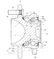
このような車輪用軸受装置の一例として図4に示すような構造が知られている。この車輪用軸受装置は、内方部材51と外方部材52、および両部材51、52間に転動自在に収容された複列のボール53、53とを備えている。内方部材51は、ハブ輪54と、このハブ輪54に所定のシメシロを介して圧入された内輪55とからなる。内輪55は、ハブ輪54の小径段部54aに圧入されると共に、小径段部54aの端部を塑性変形させて形成した加締部56によって軸方向に固定されている。
As an example of such a wheel bearing device, a structure as shown in FIG. 4 is known. This wheel bearing device includes an
内輪55の外周にはパルサリング57が圧入されている。このパルサリング57は、円環状に形成された支持環58と、この支持環58の側面に加硫接着等で一体に接合された磁気エンコーダ59とで構成されている。
A
外方部材52と内輪55との間に形成される環状空間の開口部にはキャップ60が装着され、軸受内部に封入されたグリースの外部への漏洩と、外部から雨水やダスト等が軸受内部に侵入するのを防止している。
A
キャップ60は外方部材52のインナー側の端部に内嵌固定され、外方部材52の開口部を閉塞している。このキャップ60は、オーステナイト系ステンレス鋼板をプレス成形してカップ状に形成され、外方部材52の端部内周に圧入される円筒状の嵌合部60aと、この嵌合60aから縮径部60bを介して径方向内方に延び、内方部材51の端部を覆う底部60cとを備えている。
The
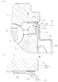
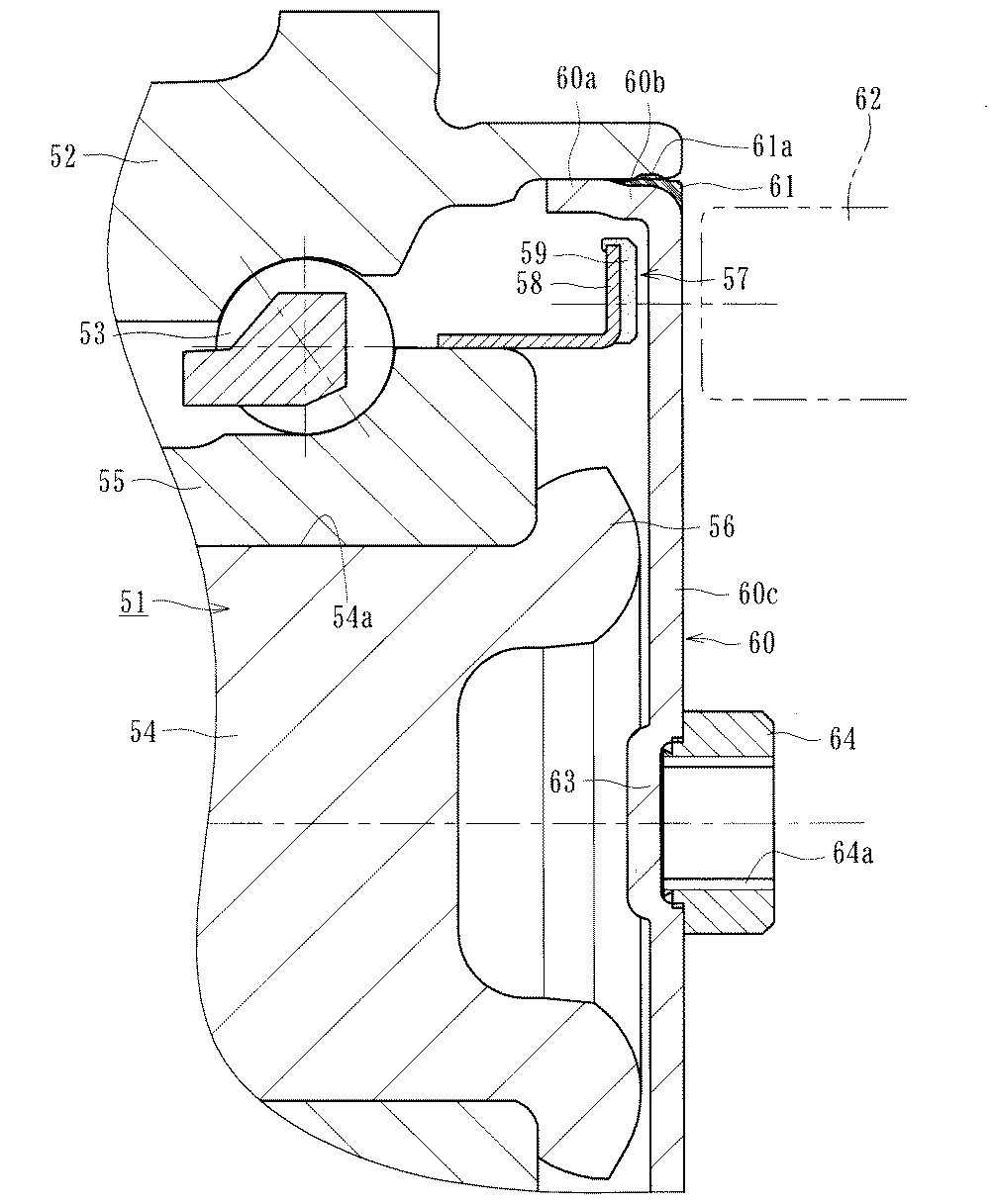
ここで、縮径部60bの外周にはNBR(アクリロニトリル−ブタジエンゴム)等の合成ゴムからなる弾性部材61が加硫接着によって一体に接合されている。この弾性部材61は、キャップ60の底部60cの側面から内方側に突出して回転速度センサ62に干渉しないように接合され、嵌合部60aの外径より径方向外方に突出する環状突起61aを備えている。そして、この環状突起61aがキャップ60の嵌合時に外方部材52の端部内周に弾性変形して圧着され、嵌合部60aの気密性を高めている。
Here, an
また、キャップ60の底部60cの径方向略中心部に円形凹所63が形成され、この円形凹所63にナット64が圧入固定されている。そして、図示しない取付フランジを介して固定ボルトをナット64の雌ねじ64aに締結することにより、回転速度センサ62がキャップ60に固定される。これにより、固定ボルトの締結時に、キャップ60に片寄ったトルクが発生せず、スムーズに回転速度センサ62を固定することができる。
In addition, a circular recess 63 is formed at a substantially central portion in the radial direction of the
また、キャップ60の底部60cの径方向外方部の磁気エンコーダ59に対応する位置に回転速度センサ62が衝合または近接するまで対向配置されている。そして、底部60cを介して磁気エンコーダ59の磁束の変化を回転速度センサ62によって検出し、車輪の回転速度を検出する。これにより、所望のエアギャップが得られ、煩雑なエアギャップ調整を省いて組立作業性の向上を図ることができると共に、検出部がキャップ60によって閉塞されているので、感知性能に影響を及ぼすことなく密封性を確保した回転速度検出装置付き車輪用軸受装置を提供することができる(例えば、特許文献1参照。)。
Further, the
このような従来の車輪用軸受装置では、外方部材52の端部に装着されるキャップ60に弾性部材61が一体に接合され、この弾性部材61が嵌合部60aの外径より径方向外方に突出する環状突起61aを備えているので、キャップ60の嵌合時に外方部材52の端部内周に環状突起61aが弾性変形して圧着され、嵌合部60aの気密性を高めることができるという特徴を有している。
In such a conventional wheel bearing device, the
然しながら、キャップ60の縮径部60bの外周に弾性部材61が接合され、この縮径部60bと磁気エンコーダ59が接合された支持環58が軸方向の同位置にあるため、キャップ60と磁気エンコーダ59が干渉する恐れがある。すなわち、磁気エンコーダ59との干渉を回避するため、キャップ60の外径を大きくするか、あるいは支持環58の外径を小さくする必要があり、設計自由度が規制されるといった課題があった。
However, the
さらに、外方部材52の端部に装着されるキャップ60が、耐食性を有し、回転速度センサ62の感知性能に悪影響を及ぼさないように、SUS304等の非磁性体のオーステナイト系ステンレス鋼板からプレス加工によってカップ状に形成されているが、この種のオーステナイト系ステンレス鋼板は、板状の鋼板からカップ状に絞り加工される際、特に、その加工度が大きくなる折り曲げ部の組織がマルテンサイト化し、非磁性体から磁性体に変態する。そのため、折り曲げ部は、外部からの磁気の影響を受けて磁化し、回転速度センサ62の感知性能に悪影響を及ぼす恐れがある。具体的には、組織がマルテンサイト化しただけでは磁気は帯びていないが、例えば、磁気を帯びた金型や治工具等の周辺部品に近付けられた場合、キャップ60が磁性体に変態しているため磁化される。
Further, the
ここで、磁気エンコーダ59の磁力が回転速度センサ62の検出限界に対して充分な余裕がある場合は、キャップ60が磁性体に変態したことによる感知性能への影響は無視できるが、回転速度センサ62の検出限界に対して、磁気エンコーダ59の磁力に余裕がない場合、つまり、磁気エンコーダ59自体の磁力が小さいか磁気エンコーダ59と回転速度センサ62とのエアギャップ等が大きい場合、その影響を無視することはできない。
Here, when the magnetic force of the
本発明は、こうした従来技術の問題点に鑑みてなされたものであり、キャップの磁気エンコーダに対応する位置に回転速度センサが衝合または近接し、キャップを介して回転速度を検出するタイプの車輪用軸受装置において、キャップがSUS304をベースとした鋼板で絞り加工され、この絞り加工によって組織がマルテンサイト化し難い非磁性体のオーステナイト系ステンレス鋼板に着目し、キャップが回転速度センサの感知性能に悪影響を及ぼさず、かつ、回転速度センサの検出限界に対して所望の検出精度を確保して信頼性の向上を図った車輪用軸受装置を提供することを目的とする。 The present invention has been made in view of such problems of the prior art, and a wheel of a type in which a rotation speed sensor collides or approaches a position corresponding to a magnetic encoder of a cap and detects the rotation speed via the cap. In a bearing device, the cap is drawn with a steel plate based on SUS304. Focusing on the non-magnetic austenitic stainless steel plate whose structure is difficult to be martensitic by this drawing, the cap has an adverse effect on the sensing performance of the rotational speed sensor. It is an object of the present invention to provide a wheel bearing device that achieves a desired detection accuracy with respect to the detection limit of the rotational speed sensor and improves reliability.
係る目的を達成すべく、本発明のうち請求項1記載の発明は、内周に複列の外側転走面が一体に形成された外方部材と、一端部に車輪を取り付けるための車輪取付フランジを一体に有し、外周に軸方向に延びる小径段部が形成されたハブ輪、およびこのハブ輪の小径段部に圧入された少なくとも一つの内輪からなり、外周に前記複列の外側転走面に対向する複列の内側転走面が形成された内方部材と、この内方部材と前記外方部材のそれぞれの転走面間に転動自在に収容された複列の転動体と、前記内輪に外嵌された磁気エンコーダと、を備え、前記外方部材のインナー側の端部にキャップが装着され、前記外方部材と内輪とで形成される環状空間の開口部が密封されると共に、前記キャップを介して前記磁気エンコーダと回転速度センサがエアギャップをもって対峙された車輪用軸受装置において、前記キャップがカップ状に形成され、前記外方部材の端部内周に圧入される円筒状の嵌合部と、この嵌合部から径方向内方に延び、側面に前記回転速度センサの検出部が近接または当接される円板状の遮蔽部とを備えると共に、当該キャップが、SUS304をベースに、C量を減量し、Ni量を増量したオーステナイト系ステンレス鋼板で形成され、マルテンサイト変態部と非マルテンサイト部の磁束密度の差が1.4mT以下に設定されている。 In order to achieve such an object, the invention according to claim 1 of the present invention includes an outer member in which a double row outer rolling surface is integrally formed on the inner periphery, and a wheel attachment for attaching a wheel to one end. The hub ring has a flange integrally formed with a small diameter step portion extending in the axial direction on the outer periphery, and at least one inner ring press-fitted into the small diameter step portion of the hub ring. An inner member in which a double-row inner rolling surface facing the running surface is formed, and a double-row rolling element that is movably accommodated between the inner and outer members. And a magnetic encoder externally fitted to the inner ring, a cap is attached to the inner side end of the outer member, and an opening of an annular space formed by the outer member and the inner ring is sealed And the magnetic encoder and the rotation speed sensor are connected via the cap. In the wheel bearing device opposed to the gap, the cap is formed in a cup shape, and a cylindrical fitting portion that is press-fitted into the inner periphery of the end of the outer member, and radially inward from the fitting portion. An austenite that has a disc-shaped shielding portion that extends and has a side surface on which the detection unit of the rotational speed sensor approaches or abuts, and that the cap is based on SUS304 and reduces the amount of C and increases the amount of Ni The magnetic flux density difference between the martensitic transformation part and the non-martensite part is set to 1.4 mT or less.
このように、内輪に外嵌された磁気エンコーダを備え、外方部材のインナー側の端部にキャップが装着され、外方部材と内輪とで形成される環状空間の開口部が密封されると共に、キャップを介して磁気エンコーダと回転速度センサがエアギャップをもって対峙された内輪回転タイプの車輪用軸受装置において、キャップがカップ状に形成され、外方部材の端部内周に圧入される円筒状の嵌合部と、この嵌合部から径方向内方に延び、側面に回転速度センサの検出部が近接または当接される円板状の遮蔽部とを備えると共に、当該キャップが、SUS304をベースに、C量を減量し、Ni量を増量したオーステナイト系ステンレス鋼板で形成され、マルテンサイト変態部と非マルテンサイト部の磁束密度の差が1.4mT以下に設定されているので、その加工度が大きくなる折り曲げ部の絞り加工後の組織がマルテンサイト変態するのを抑制し、折り曲げ部の近傍に磁気を発する磁気エンコーダが配設されていても、その残留磁束密度を抑えることができるので、回転速度センサの感知性能に悪影響を及ぼすのを防止し、かつ、回転速度センサの測定限界に対して所望の検出精度を確保して信頼性の向上を図った車輪用軸受装置を提供することができる。 As described above, the magnetic encoder that is externally fitted to the inner ring is provided, the cap is attached to the inner side end of the outer member, and the opening of the annular space formed by the outer member and the inner ring is sealed. In the inner ring rotation type wheel bearing device in which the magnetic encoder and the rotation speed sensor are opposed to each other with an air gap through the cap, the cap is formed in a cup shape and is cylindrically inserted into the inner periphery of the end of the outer member. The cap includes a fitting portion and a disc-shaped shielding portion that extends radially inward from the fitting portion, and on the side surface of which the detection portion of the rotation speed sensor approaches or contacts, and the cap is based on SUS304. In addition, it is formed of an austenitic stainless steel plate with a reduced amount of C and an increased amount of Ni, and the difference in magnetic flux density between the martensitic transformation part and the non-martensite part is set to 1.4 mT or less. Therefore, even if a magnetic encoder that generates magnetism is disposed near the bent portion, the residual magnetic flux density is reduced even if a magnetic encoder that generates magnetism in the vicinity of the bent portion is suppressed. Since it can be suppressed, the bearing for the wheel prevents the adverse effect on the sensing performance of the rotational speed sensor and ensures the desired detection accuracy with respect to the measurement limit of the rotational speed sensor to improve the reliability. An apparatus can be provided.
また、請求項2に記載の発明のように、前記キャップの素材となる鋼板のC量が0.030wt%以下、Ni量が9.00〜13.00wt%に設定されていれば、加工性を向上させると共に、オーステナイト安定度を確保し、加工度が大きくなる折り曲げ部の絞り加工後の組織がマルテンサイト変態するのを抑制することができる。
Further, as in the invention described in
また、請求項3に記載の発明のように、前記キャップの板厚が0.2〜1.0mmの範囲に設定されていれば、キャップの形状を精度良く成形することができ、強度、剛性を確保することができると共に、エアギャップが大きくなって検出精度が低下するのを防止し、また、成形時の加工度が大きくなってマルテンサイト変態化するのを抑制することができる。
Further, as in the invention described in
また、請求項4に記載の発明のように、前記キャップが、前記嵌合部の端部に縮径部が形成され、この縮径部を介して径方向内方に延びる前記遮蔽部と、この遮蔽部から円筒部を介して前記内方部材のインナー側の端部を塞ぐ底部を備えると共に、前記縮径部の外周部に合成ゴムからなるシール部材が固着され、このシール部材が、環状部と、この環状部から径方向外方に突出した環状の凸部とからなり、前記環状部が前記キャップの嵌合部の外径よりも小径に形成されると共に、前記凸部が前記嵌合部の外径よりも大径に形成され、この凸部が前記外方部材の端部内周面に圧着されていれば、キャップの嵌合面の気密性を高めることができると共に、キャップの圧入時、シール部材の凸部が圧縮されて隆起しても、環状部が逃げ部となってそれを許容し、外方部材の端面よりも突出して傷付くのを防止することができ、気密性を一層向上させることができる。
Further, as in the invention according to
本発明に係る車輪用軸受装置は、内周に複列の外側転走面が一体に形成された外方部材と、一端部に車輪を取り付けるための車輪取付フランジを一体に有し、外周に軸方向に延びる小径段部が形成されたハブ輪、およびこのハブ輪の小径段部に圧入された少なくとも一つの内輪からなり、外周に前記複列の外側転走面に対向する複列の内側転走面が形成された内方部材と、この内方部材と前記外方部材のそれぞれの転走面間に転動自在に収容された複列の転動体と、前記内輪に外嵌された磁気エンコーダと、を備え、前記外方部材のインナー側の端部にキャップが装着され、前記外方部材と内輪とで形成される環状空間の開口部が密封されると共に、前記キャップを介して前記磁気エンコーダと回転速度センサがエアギャップをもって対峙された車輪用軸受装置において、前記キャップがカップ状に形成され、前記外方部材の端部内周に圧入される円筒状の嵌合部と、この嵌合部から径方向内方に延び、側面に前記回転速度センサの検出部が近接または当接される円板状の遮蔽部とを備えると共に、当該キャップが、SUS304をベースに、C量を減量し、Ni量を増量したオーステナイト系ステンレス鋼板で形成され、マルテンサイト変態部と非マルテンサイト部の磁束密度の差が1.4mT以下に設定されているので、その加工度が大きくなる折り曲げ部の絞り加工後の組織がマルテンサイト変態するのを抑制し、折り曲げ部の近傍に磁気を発する磁気エンコーダが配設されていても、その残留磁束密度を抑えることができるので、回転速度センサの感知性能に悪影響を及ぼすのを防止し、かつ、回転速度センサの測定限界に対して所望の検出精度を確保して信頼性の向上を図った車輪用軸受装置を提供することができる。 The wheel bearing device according to the present invention integrally has an outer member integrally formed with a double row outer rolling surface on the inner periphery, and a wheel mounting flange for mounting the wheel on one end, and on the outer periphery. A hub ring formed with a small-diameter step portion extending in the axial direction, and at least one inner ring press-fitted into the small-diameter step portion of the hub ring, the inner side of the double row facing the outer rolling surface of the double row on the outer periphery An inner member on which a rolling surface is formed, a double row rolling element that is slidably accommodated between the rolling surfaces of the inner member and the outer member, and the inner ring is externally fitted to the inner ring. A magnetic encoder, and a cap is attached to an inner side end of the outer member, and an opening of an annular space formed by the outer member and the inner ring is sealed, and the The magnetic encoder and rotational speed sensor face each other with an air gap. In the wheel bearing device, the cap is formed in a cup shape, a cylindrical fitting portion that is press-fitted into the inner periphery of the end portion of the outer member, and extends radially inward from the fitting portion on the side surface. An austenitic stainless steel plate having a disc-shaped shielding portion that is close to or in contact with the detection unit of the rotational speed sensor, and the cap is made of SUS304 with a reduced amount of C and an increased amount of Ni. Since the difference in magnetic flux density between the martensite transformation part and the non-martensite part is set to 1.4 mT or less, the structure after drawing of the bent part where the degree of work is large is subject to martensite transformation. Even if a magnetic encoder that suppresses and generates magnetism in the vicinity of the bent portion is provided, the residual magnetic flux density can be suppressed, which adversely affects the sensing performance of the rotational speed sensor. It prevents the and it is possible to provide a wheel bearing apparatus with improved reliability by ensuring the desired detection accuracy for the measurement limit of the rotational speed sensor.
外周にナックルに取り付けられるための車体取付フランジを一体に有し、内周に複列の外側転走面が一体に形成された外方部材と、一端部に車輪を取り付けるための車輪取付フランジを一体に有し、外周に前記複列の外側転走面に対向する一方の内側転走面と、この内側転走面から軸方向に延びる小径段部が形成されたハブ輪、およびこのハブ輪の小径段部に圧入され、前記複列の外側転走面に対向する他方の内側転走面が形成された内輪からなる内方部材と、この前記内方部材と外方部材のそれぞれの転走面間に転動自在に収容された複列の転動体と、前記内輪に外嵌された磁気エンコーダと、を備え、前記外方部材のインナー側の端部にキャップが装着され、前記外方部材と内輪とで形成される環状空間の開口部が密封されると共に、前記キャップを介して前記磁気エンコーダと回転速度センサがエアギャップをもって対峙された車輪用軸受装置において、前記キャップがカップ状に形成され、前記外方部材の端部内周に圧入される円筒状の嵌合部と、この嵌合部から径方向内方に延び、側面に前記回転速度センサの検出部が近接または当接される円板状の遮蔽部とを備えると共に、当該キャップが、SUS304をベースに、C量が0.030wt%以下、Ni量が9.00〜13.00wt%に設定されたオーステナイト系ステンレス鋼板で形成され、マルテンサイト変態部と非マルテンサイト部の磁束密度の差が1.4mT以下に設定されている。 A vehicle body mounting flange to be attached to the knuckle on the outer periphery, an outer member in which a double row outer rolling surface is integrally formed on the inner periphery, and a wheel mounting flange to mount a wheel on one end A hub wheel integrally formed and having one inner rolling surface opposed to the double-row outer rolling surface on the outer periphery, and a small-diameter step portion extending in the axial direction from the inner rolling surface, and the hub wheel An inner member formed of an inner ring that is press-fitted into the small-diameter step portion and formed with the other inner rolling surface opposite to the double row outer rolling surface, and the inner member and the outer member. A double row rolling element accommodated between the running surfaces, and a magnetic encoder externally fitted to the inner ring, and a cap is attached to an inner side end of the outer member, The opening of the annular space formed by the side member and the inner ring is sealed and the front In a wheel bearing device in which the magnetic encoder and the rotational speed sensor are opposed to each other with an air gap through a cap, the cap is formed in a cup shape and is fitted into a cylindrical shape that is press-fitted into the inner periphery of the end of the outer member. And a disc-shaped shielding portion that extends radially inward from the fitting portion and that is close to or abutted with the detection portion of the rotational speed sensor on the side surface, and the cap is based on SUS304. , The austenitic stainless steel sheet in which the C content is 0.030 wt% or less and the Ni content is set to 9.00 to 13.00 wt%, the difference in magnetic flux density between the martensitic transformation part and the non-martensite part is 1. It is set to 4 mT or less.
以下、本発明の実施の形態を図面に基づいて詳細に説明する。
図1は、本発明に係る車輪用軸受装置の一実施形態を示す縦断面図、図2(a)は、図1の要部拡大図、(b)は、(a)の部分拡大図、図3は、残留磁束密度の測定方法を示す説明図である。なお、以下の説明では、車両に組み付けた状態で車両の外側寄りとなる側をアウター側(図1の左側)、中央寄り側をインナー側(図1の右側)という。
Hereinafter, embodiments of the present invention will be described in detail with reference to the drawings.
1 is a longitudinal sectional view showing an embodiment of a wheel bearing device according to the present invention, FIG. 2 (a) is an enlarged view of a main part of FIG. 1, and (b) is a partially enlarged view of (a). FIG. 3 is an explanatory diagram showing a method for measuring the residual magnetic flux density. In the following description, the side closer to the outer side of the vehicle when assembled to the vehicle is referred to as the outer side (left side in FIG. 1), and the side closer to the center is referred to as the inner side (right side in FIG. 1).
図1に示す車輪用軸受装置は第3世代と称される従動輪用であって、内方部材1と外方部材2、および両部材1、2間に転動自在に収容された複列の転動体(ボール)3、3とを備えている。内方部材1は、ハブ輪4と、このハブ輪4に所定のシメシロを介して圧入された内輪5とからなる。
The wheel bearing device shown in FIG. 1 is for a driven wheel referred to as a third generation, and is a double row accommodated in a freely rollable manner between an inner member 1 and an
外方部材2はS53C等の炭素0.40〜0.80wt%を含む中高炭素鋼からなり、外周にナックル(図示せず)に取り付けるための車体取付フランジ2bを一体に有し、内周に複列の外側転走面2a、2aが一体に形成されている。これら複列の外側転走面2a、2aは、高周波焼入れによって表面硬さを58〜64HRCの範囲に硬化層が形成されている。
The
ハブ輪4は、アウター側の端部に車輪(図示せず)を取り付けるための車輪取付フランジ6を一体に有し、この車輪取付フランジ6の円周等配位置にハブボルト6aが植設されている。また、外周に前記複列の外側転走面2a、2aの一方(アウター側)に対向する内側転走面4aと、この内側転走面4aから軸方向に延びる小径段部4bが形成されている。
The
一方、内輪5は外周に前記複列の外側転走面2a、2aの他方(インナー側)に対向する内側転走面5aが形成され、ハブ輪4の小径段部4bに所定のシメシロを介して圧入されている。そして、ハブ輪4の小径段部4bの端部を径方向外方に塑性変形させて形成した加締部7によって所定の軸受予圧が付与された状態で軸方向に固定されている。
On the other hand, the
外方部材2の複列の外側転走面2a、2aと、これらに対向する複列の内側転走面4a、5a間には複列の転動体3、3がそれぞれ収容され、保持器8、8によって転動自在に保持されている。また、外方部材2と内方部材1との間に形成される環状空間の開口部のうちアウター側の開口部にはシール9が装着されると共に、インナー側の開口部にはキャップ10が装着され、軸受内部に封入された潤滑グリースの漏洩と、外部から軸受内部に雨水やダスト等が侵入するのを防止している。
Between the double row
なお、ここでは、転動体3にボールを使用した複列アンギュラ玉軸受で構成された車輪用軸受装置を例示したが、これに限らず、転動体3に円錐ころを使用した複列円錐ころ軸受で構成されていても良い。また、ここでは、ハブ輪4の外周に直接内側転走面4aが形成された第3世代構造を例示したが、図示はしないが、ハブ輪の小径段部に一対の内輪が圧入固定された第1世代または第2世代構造であっても良い。
In addition, although the wheel bearing apparatus comprised by the double row angular contact ball bearing which used the ball for the rolling
ハブ輪4はS53C等の炭素0.40〜0.80wt%を含む中高炭素鋼からなり、内側転走面4aをはじめ車輪取付フランジ6のインナー側の基部6bから小径段部4bに亙って高周波焼入れによって表面硬さを58〜64HRCの範囲に硬化処理が施されている。なお、加締部7は鍛造加工後の表面硬さのままとされている。これにより、シール9のシールランド部となる基部6bの耐摩耗性が向上するばかりでなく、車輪取付フランジ6に負荷される回転曲げ荷重に対して充分な機械的強度を有し、ハブ輪4の耐久性が向上すると共に、加締加工が容易となり、加工時の微小クラックの発生を防止するができる。
The
また、内輪5および転動体3はSUJ2等の高炭素クロム軸受鋼からなり、ズブ焼入れにより内輪5は芯部まで58〜64HRCの範囲、転動体3は芯部まで62〜67HRCの範囲で硬化処理されている。
The
シール9は、外方部材2のアウター側端部の内周に所定のシメシロを介して圧入された芯金11と、この芯金11に接合されたシール部材12とからなる一体型のシールで構成されている。芯金11は、オーステナイト系ステンレス鋼板(JIS規格のSUS304系等)や冷間圧延鋼板(JIS規格のSPCC系等)、フェライト系のステンレス鋼板(JIS規格のSUS430系等)をプレス加工にて断面L字状に形成されている。
The seal 9 is an integrated seal composed of a
一方、シール部材12はNBR(アクリロニトリル−ブタジエンゴム)等の合成ゴムからなり、加硫接着によって芯金11に一体に接合されている。このシール部材12は、径方向外方に傾斜して形成され、断面が円弧状に形成された車輪取付フランジ6のインナー側の基部6bに所定の軸方向シメシロをもって摺接する一対のサイドリップ12a、12bと、軸受内方側に傾斜して形成されたグリースリップ12cを有している。
On the other hand, the seal member 12 is made of synthetic rubber such as NBR (acrylonitrile-butadiene rubber) and is integrally joined to the
内輪5には、断面L字形に、全体として円環状に形成された支持環13が外嵌されている。この支持環13は、図2(a)に拡大して示すように、内輪5の大径側の外周面に圧入される円筒部13aと、この円筒部13aから径方向外方に延びる立板部13bとを備え、立板部13bのインナー側の側面に磁気エンコーダ14が加硫接着によって一体に接合されている。磁気エンコーダ14は、ゴム等のエラストマにフェライト等の磁性体粉が混入され、周方向に交互に等ピッチで磁極N、Sが着磁されて車輪の回転速度検出用のロータリエンコーダを構成している。
The
また、支持環13は、強磁性体の鋼板、例えば、フェライト系のステンレス鋼板(JIS規格のSUS430系等)や防錆処理された冷間圧延鋼板からプレス加工にて形成されている。これにより、支持環13が発錆するのを防止すると共に、磁気エンコーダ14の磁気出力が強くなり安定した検出精度を確保することができる。
The
外方部材2のインナー側の端部に装着されたキャップ10はオーステナイト系ステンレス鋼板からカップ状に形成され、外方部材2のインナー側の端部内周2dに圧入される円筒状の嵌合部10aと、この嵌合部10aから縮径部10bを介して径方向内方に延びる円板状の遮蔽部10cと、この遮蔽部10cから円筒部10dを介して内方部材1のインナー側の端部を塞ぐ底部10eとを備えている。そして、回転速度センサ16の検出部16aは、キャップ10の遮蔽部10cに近接または当接され、検出部16aと磁気エンコーダ14とはキャップ10を介して所定のエアギャップ(軸方向すきま)で対向配置されている。こうした段付き形状によってキャップ10の剛性が高くなり、飛石等による変形を抑えることができると共に、耐食性に優れ、長期間に亘って耐久性を向上させることができる。
The
なお、ここでは、キャップ10の板厚が0.2〜1.0mmの範囲に設定されている。何故なら、板厚が0.2mm未満では、キャップ10の形状を精度良く成形することが難しくなると共に、強度、剛性が低下し、組立工程あるいは走行中に飛石等で変形する恐れがあるので好ましくない。また、板厚が1.0mmを超えるとエアギャップが大きくなって所望の磁気特性を得ることが難しくなって検出精度が低下すると共に、後述するように、成形時の加工度が大きくなってマルテンサイト変態化し易くなって好ましくない。
Here, the plate thickness of the
本実施形態では、(b)に示すように、キャップ10の縮径部10bは、段付き形状をなし、その外周部にシール部材15が固着されている。このシール部材15はNBR等の合成ゴムからなり、加硫接着によってキャップ10に一体に接合され、凸部15aと環状部15bとからなる。環状部15bは嵌合部10aの外径よりも僅かに小径に形成されると共に、凸部15aは嵌合部10aの外径よりも僅かに大径に形成され、つまり、外方部材2の端部内周面2dに凸部15aが所定のシメシロを介して圧入され、嵌合面の気密性を高めることができる。また、キャップ10の圧入時、シール部材15の凸部15aが圧縮されて隆起しても、この環状部15bが逃げ部となってそれを許容し、外方部材2の端面2cよりも突出して傷付くのを防止することができ、一層気密性を向上させることができる。
In this embodiment, as shown in (b), the reduced
ここで、キャップ10は、表1に示す従来のオーステナイト系ステンレス鋼板、JIS規格のSUS304(比較例)に対して、表2に示すように、基本的には、SUS304をベースに、C量を減量し、Ni量を増量した本発明に係る鋼板(実施例)によって形成されている。
Here, the
C:Cはオーステナイト生成元素であり、オーステナイト安定度を確保する目的で添加されるが、多量に添加すると硬質になり加工性が低下するため0.030wt%以下(0%は含まず)の含有量とする。 C: C is an austenite-forming element and is added for the purpose of ensuring austenite stability. However, if added in a large amount, it becomes hard and the workability is lowered, so the content is 0.030 wt% or less (excluding 0%). Amount.
Si:Siは強力な脱酸剤として有効であるが多量に添加されると硬質になると共に、製造性を阻害するため1.00wt%以下(0%を含まず)の含有量とする。 Si: Si is effective as a strong deoxidizing agent, but when added in a large amount, it becomes hard, and in order to inhibit manufacturability, the content is 1.00 wt% or less (not including 0%).
Mn:Mnはオーステナイト生成元素であり、オーステナイト安定度の確保と深絞り成形性の向上を目的に添加するが、多量に添加するとMnSを形成し耐食性が低下するため2.00wt%以下(0%を含まず)の含有量とする。 Mn: Mn is an austenite-forming element and is added for the purpose of securing austenite stability and improving deep drawability. However, if added in a large amount, MnS is formed and the corrosion resistance is lowered, so that it is 2.00 wt% or less (0% Content).
P:Pは焼入れ時のオーステナイト粒界に偏析して焼割れの発生を助長するので、極力低減することが好ましく、この観点から0.045wt%以下に抑制するものとした。 P: P segregates at the austenite grain boundary during quenching and promotes the occurrence of cracking. Therefore, it is preferable to reduce it as much as possible, and from this point of view, it is suppressed to 0.045 wt% or less.
S:Sは鋼中でMnSを形成し被削性を向上させる効果があるので0.010wt%以上含有させるものとした。しかし、MnSは、亀裂の起点となり易く、強度、靱性の低下を招くので、S量の上限は0.030wt%に限定した。 S: Since S has the effect of improving the machinability by forming MnS in the steel, it is contained in an amount of 0.010 wt% or more. However, since MnS tends to be a starting point of cracks and causes a decrease in strength and toughness, the upper limit of the amount of S is limited to 0.030 wt%.
Ni:Niはオーステナイト系ステンレス鋼には不可欠な元素であり、オーステナイト安定度および加工性の確保の点で9.00wt%以上の含有量とする。なお、ここでは、Niは高価な金属であるため、経済性を考慮して含有量の上限を13.00wt%とする。 Ni: Ni is an indispensable element for austenitic stainless steel, and its content is 9.00 wt% or more in terms of ensuring austenite stability and workability. Here, since Ni is an expensive metal, the upper limit of the content is set to 13.00 wt% in consideration of economy.
Cr:Crは十分な耐食性を得るためには15wt%以上必要であるので、含有量の下限を18.00wt%以上とすると共に、多量に添加されるとδ−フェライトを形成し、成形性を低下させ、また、多量に添加されると製造性が劣化するため、含有量の上限を20.00wt%とする。そして、残部Feおよび不可避的不純物の組成を有している。 Cr: Cr needs to be 15 wt% or more in order to obtain sufficient corrosion resistance. Therefore, the lower limit of the content is set to 18.00 wt% or more, and when added in a large amount, δ-ferrite is formed, and formability is improved. If the content is reduced and added in a large amount, the manufacturability deteriorates, so the upper limit of the content is made 20.00 wt%. And it has the composition of remainder Fe and inevitable impurities.
本出願人はキャップ10を強制磁化し、その残留磁束密度に対して、ABSのセンシングへの影響度を測定した。その測定結果を表3に示す。
The present applicant forcibly magnetized the
評価方法としては、図3に示すように、測定の径方向位置は、回転速度センサ(ABS)16の検出部16aの面の外周側が、キャップ10の縮径部10bの端部(折り曲げ部の終わり)R部10fとし、また、測定の軸方向位置は、キャップ10の遮蔽部10cのインナー側の側面から回転速度センサ16の検出部16aまでの距離0.5mmとした。なお、回転速度センサ16は、ホール素子およびこの素子の出力波形を整える波形整形回路が組み込まれたIC等からなるものを使用した。
As an evaluation method, as shown in FIG. 3, the radial position of the measurement is such that the outer peripheral side of the surface of the
この表3が示すように、キャップ10の強制磁化による残留磁束密度の飽和値が1.4mT以下(好ましくは、0.4mT以下)であれば、センシングに影響がなく、実用可能であることが判った。つまり、実際の使用において、折り曲げ部(嵌合部10aおよび縮径部10b)の近傍に磁気を発する磁気エンコーダが配設された場合を想定してキャップ10を強制磁化し、キャップ10の各部位において、絞り加工後の組織がマルテンサイト変態するのを抑制できることが判った。
As shown in Table 3, if the saturation value of the residual magnetic flux density due to the forced magnetization of the
すなわち、絞り加工後の組織がマルテンサイト変態する部位(折り曲げ部)と、絞り加工されない非マルテンサイト部位(底部)との磁束密度の差が、従来のSUS304(比較例)では、いずれも1.6mT以上であったのに対し、本発明に係る鋼板では、いずれも1.4mT以下であった。これにより、この種の形状のキャップ10であれば、折り曲げ部の近傍に磁気を発する磁気エンコーダが配設されていても、その残留磁束密度を1.4mT以下に抑えることができるので、回転速度センサ16の感知性能に悪影響を及ぼすのを防止し、かつ、回転速度センサ16の測定限界に対して所望の検出精度を確保して信頼性の向上を図った車輪用軸受装置を提供することができる。
That is, in the conventional SUS304 (comparative example), the difference in magnetic flux density between the site where the microstructure after drawing is martensitic transformed (folded portion) and the non-martensitic site that is not drawn (bottom) is 1. While it was 6 mT or more, all of the steel sheets according to the present invention were 1.4 mT or less. Thus, with this type of
以上、本発明の実施の形態について説明を行ったが、本発明はこうした実施の形態に何等限定されるものではなく、あくまで例示であって、本発明の要旨を逸脱しない範囲内において、さらに種々なる形態で実施し得ることは勿論のことであり、本発明の範囲は、特許請求の範囲の記載によって示され、さらに特許請求の範囲に記載の均等の意味、および範囲内のすべての変更を含む。 The embodiment of the present invention has been described above, but the present invention is not limited to such an embodiment, and is merely an example, and various modifications can be made without departing from the scope of the present invention. Of course, the scope of the present invention is indicated by the description of the scope of claims, and further, the equivalent meanings described in the scope of claims and all modifications within the scope of the scope of the present invention are included. Including.
本発明に係る車輪用軸受装置は、転動体がボールや円錐ころ等、あらゆる構造の内輪回転タイプで、外方部材のインナー側の端部にキャップが装着された従動輪用の車輪用軸受装置に適用することができる。 The wheel bearing device according to the present invention is a wheel bearing device for a driven wheel in which the rolling element is an inner ring rotating type of any structure such as a ball or a tapered roller, and a cap is attached to the inner side end of the outer member. Can be applied to.
1 内方部材
2 外方部材
2a 外側転走面
2b 車体取付フランジ
2c 外方部材のインナー側の端面
2d 外方部材の端部内周面
3 転動体
4 ハブ輪
4a、5a 内側転走面
4b 小径段部
5 内輪
6 車輪取付フランジ
6a ハブボルト
6b 車輪取付フランジのインナー側の基部
7 加締部
8 保持器
9 アウター側のシール
10 キャップ
10a 嵌合部
10b 縮径部
10c 遮蔽部
10d、13a 円筒部
10e 底部
10f キャップの縮径部のR部
11 芯金
12、15 シール部材
12a、12b サイドリップ
12c グリースリップ
13 支持環
13b 立板部
14 磁気エンコーダ
15a 凸部
15b 環状部
16 回転速度センサ
16a 検出部
51 内方部材
52 外方部材
53 ボール
54 ハブ輪
54a 小径段部
55 内輪
56 加締部
57 パルサリング
58 支持環
59 磁気エンコーダ
60 キャップ
60a 嵌合部
60b 縮径部
60c 底部
61 弾性部材
61a 環状突起
62 回転速度センサ
63 円形凹所
64 固定ナット
64a 雌ねじ
DESCRIPTION OF SYMBOLS 1
Claims (4)
一端部に車輪を取り付けるための車輪取付フランジを一体に有し、外周に軸方向に延びる小径段部が形成されたハブ輪、およびこのハブ輪の小径段部に圧入された少なくとも一つの内輪からなり、外周に前記複列の外側転走面に対向する複列の内側転走面が形成された内方部材と、
この内方部材と前記外方部材のそれぞれの転走面間に転動自在に収容された複列の転動体と、
前記内輪に外嵌された磁気エンコーダと、を備え、
前記外方部材のインナー側の端部にキャップが装着され、前記外方部材と内輪とで形成される環状空間の開口部が密封されると共に、
前記キャップを介して前記磁気エンコーダと回転速度センサがエアギャップをもって対峙された車輪用軸受装置において、
前記キャップがカップ状に形成され、前記外方部材の端部内周に圧入される円筒状の嵌合部と、この嵌合部から径方向内方に延び、側面に前記回転速度センサの検出部が近接または当接される円板状の遮蔽部とを備えると共に、
当該キャップが、SUS304をベースに、C量を減量し、Ni量を増量したオーステナイト系ステンレス鋼板で形成され、マルテンサイト変態部と非マルテンサイト部の磁束密度の差が1.4mT以下に設定されていることを特徴とする車輪用軸受装置。 An outer member in which a double row outer rolling surface is integrally formed on the inner periphery;
From a hub wheel integrally having a wheel mounting flange for mounting a wheel at one end and having a small-diameter step extending in the axial direction on the outer periphery, and at least one inner ring press-fitted into the small-diameter step of the hub ring An inner member in which a double row inner rolling surface facing the outer rolling surface of the double row is formed on the outer periphery,
A double row rolling element housed movably between the rolling surfaces of the inner member and the outer member;
A magnetic encoder fitted on the inner ring,
A cap is attached to the inner side end of the outer member, and the opening of the annular space formed by the outer member and the inner ring is sealed,
In the wheel bearing device in which the magnetic encoder and the rotation speed sensor are opposed to each other with an air gap through the cap,
The cap is formed in a cup shape, and is fitted into a cylindrical fitting portion that is press-fitted into the inner periphery of the end portion of the outer member, and extends radially inward from the fitting portion, and the detection portion of the rotational speed sensor on the side surface. And a disc-shaped shielding part that is close to or abuts,
The cap is formed of an austenitic stainless steel plate with a reduced C content and an increased Ni content based on SUS304, and the difference in magnetic flux density between the martensitic transformation part and the non-martensite part is set to 1.4 mT or less. A bearing device for a wheel.
Priority Applications (5)
| Application Number | Priority Date | Filing Date | Title |
|---|---|---|---|
| JP2015188613A JP2017062014A (en) | 2015-09-25 | 2015-09-25 | Bearing device for wheel |
| PCT/JP2016/077929 WO2017051836A1 (en) | 2015-09-25 | 2016-09-23 | Bearing device for vehicle wheel |
| DE112016004320.1T DE112016004320T5 (en) | 2015-09-25 | 2016-09-23 | wheel bearing device |
| CN201680055489.XA CN108138850B (en) | 2015-09-25 | 2016-09-23 | Wheel bearing device |
| US15/933,467 US10641336B2 (en) | 2015-09-25 | 2018-03-23 | Wheel bearing apparatus |
Applications Claiming Priority (1)
| Application Number | Priority Date | Filing Date | Title |
|---|---|---|---|
| JP2015188613A JP2017062014A (en) | 2015-09-25 | 2015-09-25 | Bearing device for wheel |
Publications (1)
| Publication Number | Publication Date |
|---|---|
| JP2017062014A true JP2017062014A (en) | 2017-03-30 |
Family
ID=58386636
Family Applications (1)
| Application Number | Title | Priority Date | Filing Date |
|---|---|---|---|
| JP2015188613A Pending JP2017062014A (en) | 2015-09-25 | 2015-09-25 | Bearing device for wheel |
Country Status (5)
| Country | Link |
|---|---|
| US (1) | US10641336B2 (en) |
| JP (1) | JP2017062014A (en) |
| CN (1) | CN108138850B (en) |
| DE (1) | DE112016004320T5 (en) |
| WO (1) | WO2017051836A1 (en) |
Cited By (2)
| Publication number | Priority date | Publication date | Assignee | Title |
|---|---|---|---|---|
| DE202018105325U1 (en) | 2017-09-19 | 2019-01-25 | Nsk Ltd. | Hub unit bearings |
| CN113056620A (en) * | 2018-10-31 | 2021-06-29 | Ntn株式会社 | Bearing device |
Families Citing this family (2)
| Publication number | Priority date | Publication date | Assignee | Title |
|---|---|---|---|---|
| WO2019208854A1 (en) * | 2018-04-27 | 2019-10-31 | 주식회사 일진글로벌 | Wheel bearing assembly |
| KR20190125108A (en) * | 2018-04-27 | 2019-11-06 | 주식회사 일진글로벌 | Wheel bearing assembly |
Citations (5)
| Publication number | Priority date | Publication date | Assignee | Title |
|---|---|---|---|---|
| JP2003082445A (en) * | 2001-07-05 | 2003-03-19 | Nisshin Steel Co Ltd | Nonmagnetic stainless steel having excellent workability |
| JP2012066661A (en) * | 2010-09-22 | 2012-04-05 | Ntn Corp | Bearing device for wheel |
| JP2012177170A (en) * | 2011-02-28 | 2012-09-13 | National Institute For Materials Science | High strength nonmagnetic austenitic stainless steel material, and method of manufacturing the same |
| JP2014214765A (en) * | 2013-04-23 | 2014-11-17 | 内山工業株式会社 | Cover manufacturing method |
| JP2014219100A (en) * | 2009-09-17 | 2014-11-20 | Ntn株式会社 | Wheel bearing device |
Family Cites Families (12)
| Publication number | Priority date | Publication date | Assignee | Title |
|---|---|---|---|---|
| JPS6035950B2 (en) * | 1976-09-14 | 1985-08-17 | 保土谷化学工業株式会社 | Method for solubilizing dyes in hydrocarbon solvents |
| JPS6114604A (en) * | 1984-06-29 | 1986-01-22 | Fujikura Ltd | Method for drawing wire body into thin diameter cylindrical body |
| JPS6359770U (en) * | 1986-10-09 | 1988-04-21 | ||
| JP3580002B2 (en) * | 1996-01-16 | 2004-10-20 | 日本精工株式会社 | Rolling bearing unit with rotation speed detector |
| CN2923437Y (en) * | 2006-04-29 | 2007-07-18 | 万向钱潮股份有限公司 | Hub bearing unit with magnetic induction ring |
| JP5453718B2 (en) * | 2008-02-08 | 2014-03-26 | 日本精工株式会社 | State quantity measuring device for rolling bearing units |
| JP5334823B2 (en) * | 2009-12-07 | 2013-11-06 | Ntn株式会社 | Wheel bearing device with rotation speed detector |
| WO2011034134A1 (en) * | 2009-09-17 | 2011-03-24 | Ntn株式会社 | Bearing device for a wheel, equipped with a rotational-speed measurement device |
| JP5592130B2 (en) | 2010-03-18 | 2014-09-17 | Ntn株式会社 | Wheel bearing device with rotation speed detector |
| JP5616758B2 (en) * | 2010-11-16 | 2014-10-29 | Ntn株式会社 | Wheel bearing device with rotation speed detector |
| CN104246257B (en) * | 2012-03-21 | 2017-03-01 | Ntn株式会社 | Vehicle bearing device |
| JP6114604B2 (en) * | 2013-03-27 | 2017-04-12 | Ntn株式会社 | Wheel bearing device with rotation speed detector |
-
2015
- 2015-09-25 JP JP2015188613A patent/JP2017062014A/en active Pending
-
2016
- 2016-09-23 CN CN201680055489.XA patent/CN108138850B/en active Active
- 2016-09-23 WO PCT/JP2016/077929 patent/WO2017051836A1/en active Application Filing
- 2016-09-23 DE DE112016004320.1T patent/DE112016004320T5/en active Pending
-
2018
- 2018-03-23 US US15/933,467 patent/US10641336B2/en active Active
Patent Citations (5)
| Publication number | Priority date | Publication date | Assignee | Title |
|---|---|---|---|---|
| JP2003082445A (en) * | 2001-07-05 | 2003-03-19 | Nisshin Steel Co Ltd | Nonmagnetic stainless steel having excellent workability |
| JP2014219100A (en) * | 2009-09-17 | 2014-11-20 | Ntn株式会社 | Wheel bearing device |
| JP2012066661A (en) * | 2010-09-22 | 2012-04-05 | Ntn Corp | Bearing device for wheel |
| JP2012177170A (en) * | 2011-02-28 | 2012-09-13 | National Institute For Materials Science | High strength nonmagnetic austenitic stainless steel material, and method of manufacturing the same |
| JP2014214765A (en) * | 2013-04-23 | 2014-11-17 | 内山工業株式会社 | Cover manufacturing method |
Cited By (3)
| Publication number | Priority date | Publication date | Assignee | Title |
|---|---|---|---|---|
| DE202018105325U1 (en) | 2017-09-19 | 2019-01-25 | Nsk Ltd. | Hub unit bearings |
| CN113056620A (en) * | 2018-10-31 | 2021-06-29 | Ntn株式会社 | Bearing device |
| CN113056620B (en) * | 2018-10-31 | 2023-02-21 | Ntn株式会社 | Bearing device |
Also Published As
| Publication number | Publication date |
|---|---|
| US10641336B2 (en) | 2020-05-05 |
| CN108138850B (en) | 2020-03-03 |
| WO2017051836A1 (en) | 2017-03-30 |
| CN108138850A (en) | 2018-06-08 |
| US20180209482A1 (en) | 2018-07-26 |
| DE112016004320T5 (en) | 2018-08-23 |
Similar Documents
| Publication | Publication Date | Title |
|---|---|---|
| US8382377B2 (en) | Wheel bearing apparatus incorporated with a wheel speed detecting apparatus | |
| JP5331640B2 (en) | Wheel bearing device with rotation speed detector | |
| JP5576222B2 (en) | Wheel bearing device | |
| US8690449B2 (en) | Wheel bearing apparatus | |
| US7618194B2 (en) | Wheel bearing apparatus incorporated with a wheel speed detecting apparatus | |
| US10641336B2 (en) | Wheel bearing apparatus | |
| JP5894389B2 (en) | Wheel bearing device | |
| JP2011117583A (en) | Bearing device for wheel, equipped with rotational-speed detection device | |
| JP4748775B2 (en) | Wheel bearing device with rotation speed detector | |
| JP4683496B2 (en) | Wheel bearing device | |
| JP2007010480A (en) | Bearing apparatus for wheel with rotation speed detection device | |
| JP4628049B2 (en) | Wheel bearing device with rotation speed detector | |
| JP2014190464A (en) | Bearing device for wheel | |
| JP6012803B2 (en) | Wheel bearing device | |
| JP2008019912A (en) | Wheel bearing device | |
| JP4573201B2 (en) | Wheel bearing device with rotation speed detector | |
| JP2006349061A (en) | Bearing device with rotational speed detector for wheel | |
| JP2013194861A (en) | Bearing device for wheel | |
| JP6239842B2 (en) | Wheel bearing device | |
| JP2012032329A (en) | Wheel bearing device with rotation speed detector | |
| JP2009228818A (en) | Bearing device adapted for use in wheel and having rotational speed detection device | |
| JP6298262B2 (en) | Wheel bearing device | |
| JP4628053B2 (en) | Wheel bearing device with rotation speed detector | |
| JP5914086B2 (en) | Wheel bearing device | |
| JP2012202415A (en) | Wheel bearing device equipped with rotational speed detection device |
Legal Events
| Date | Code | Title | Description |
|---|---|---|---|
| A621 | Written request for application examination |
Free format text: JAPANESE INTERMEDIATE CODE: A621 Effective date: 20180827 |
|
| A131 | Notification of reasons for refusal |
Free format text: JAPANESE INTERMEDIATE CODE: A131 Effective date: 20190419 |
|
| A521 | Request for written amendment filed |
Free format text: JAPANESE INTERMEDIATE CODE: A523 Effective date: 20190529 |
|
| A131 | Notification of reasons for refusal |
Free format text: JAPANESE INTERMEDIATE CODE: A131 Effective date: 20190610 |
|
| A521 | Request for written amendment filed |
Free format text: JAPANESE INTERMEDIATE CODE: A523 Effective date: 20190808 |
|
| A131 | Notification of reasons for refusal |
Free format text: JAPANESE INTERMEDIATE CODE: A131 Effective date: 20190906 |
|
| A521 | Request for written amendment filed |
Free format text: JAPANESE INTERMEDIATE CODE: A523 Effective date: 20191101 |
|
| A131 | Notification of reasons for refusal |
Free format text: JAPANESE INTERMEDIATE CODE: A131 Effective date: 20200228 |
|
| A02 | Decision of refusal |
Free format text: JAPANESE INTERMEDIATE CODE: A02 Effective date: 20200904 |