JP6239842B2 - Wheel bearing device - Google Patents
Wheel bearing device Download PDFInfo
- Publication number
- JP6239842B2 JP6239842B2 JP2013067578A JP2013067578A JP6239842B2 JP 6239842 B2 JP6239842 B2 JP 6239842B2 JP 2013067578 A JP2013067578 A JP 2013067578A JP 2013067578 A JP2013067578 A JP 2013067578A JP 6239842 B2 JP6239842 B2 JP 6239842B2
- Authority
- JP
- Japan
- Prior art keywords
- fitting
- cap
- fitted
- diameter
- outer member
- Prior art date
- Legal status (The legal status is an assumption and is not a legal conclusion. Google has not performed a legal analysis and makes no representation as to the accuracy of the status listed.)
- Active
Links
Images


Description
本発明は、自動車等の車輪を懸架装置に対して回転自在に支承する車輪用軸受装置、特に、車輪の回転速度を検出する回転速度センサが装着される車輪用軸受装置に関するものである。 The present invention relates to a wheel bearing device for rotatably supporting a wheel of an automobile or the like with respect to a suspension device, and more particularly to a wheel bearing device to which a rotation speed sensor for detecting the rotation speed of a wheel is attached.
自動車の車輪を懸架装置に対して回転自在に支承すると共に、アンチロックブレーキシステム(ABS)を制御し、車輪の回転速度を検出する回転速度検出装置が内蔵された車輪用軸受装置が一般的に知られている。従来、このような車輪用軸受装置は、転動体を介して転接する内方部材および外方部材の間にシール装置が設けられ、円周方向に磁極を交互に並べてなる磁気エンコーダを前記シール装置に一体化させると共に、磁気エンコーダと、この磁気エンコーダに対面配置され、車輪の回転に伴う磁気エンコーダの磁極変化を検出する回転速度センサとで回転速度検出装置が構成されている。 In general, a wheel bearing device in which a wheel of an automobile is rotatably supported with respect to a suspension device and an anti-lock brake system (ABS) is controlled to detect a rotation speed of the wheel is incorporated. Are known. Conventionally, in such a wheel bearing device, a sealing device is provided between an inner member and an outer member that are in rolling contact with a rolling element, and a magnetic encoder in which magnetic poles are alternately arranged in a circumferential direction is provided as the sealing device. In addition, the rotational speed detecting device is constituted by a magnetic encoder and a rotational speed sensor that is arranged facing the magnetic encoder and detects a magnetic pole change of the magnetic encoder accompanying the rotation of the wheel.
前記回転速度センサは、懸架装置を構成するナックルに車輪用軸受装置が装着された後、当該ナックルに装着されているものが一般的である。しかし、この回転速度センサと磁気エンコーダとのエアギャップの調整作業の煩雑さを解消すると共に、よりコンパクト化を狙って、最近では回転速度センサをも装着される車輪用軸受装置が提案されている。 In general, the rotational speed sensor is attached to the knuckle after the wheel bearing device is attached to the knuckle constituting the suspension device. However, in order to eliminate the complexity of adjusting the air gap between the rotational speed sensor and the magnetic encoder and to make it more compact, a wheel bearing device to which a rotational speed sensor is also attached has recently been proposed. .
このような車輪用軸受装置の一例として図9に示すような構造が知られている。この車輪用軸受装置は、内方部材51と外方部材52、および両部材51、52間に転動自在に収容された複列のボール53a、53b列とを備えている。内方部材51は、ハブ輪54と、このハブ輪54に所定のシメシロを介して圧入された内輪55とからなる。
As an example of such a wheel bearing device, a structure as shown in FIG. 9 is known. The wheel bearing device includes an
ハブ輪54は、一端部に車輪取付フランジ56を一体に有し、外周に一方の内側転走面54aと、この内側転走面54aから軸方向に延びる軸状部54dを介して小径段部54bが形成されている。
The
内輪55は、外周に他方の内側転走面55aが形成され、ハブ輪54の小径段部54bに圧入されると共に、小径段部54bの端部を塑性変形させて形成した加締部54cによって軸方向に固定されている。
The
外方部材52は、外周に車体取付フランジ52cを一体に有し、内周にハブ輪54の内側転走面54aに対向する外側転走面52aと、内輪55の内側転走面55aに対向する外側転走面52bが一体に形成されている。そして、外方部材52と内方部材51との間に形成される環状空間の開口部にシール57とセンサキャップ58が装着され、軸受内部に封入されたグリースの外部への漏洩と、外部から雨水やダスト等が軸受内部に侵入するのを防止している。
The
車輪取付フランジ56側のボール3a列のピッチ円直径PCDoが反車輪取付フランジ56側のボール3b列のピッチ円直径PCDiよりも大径に設定されると共に、ボール3a列のボール径doがボール3b列のボール径diよりも小径(do<di)に設定されている。また、このピッチ円直径PCDo、PCDiと転動体径do、diの違いにより、ボール3a列のボール数Zoがボール3b列のボール数Ziよりも多く設定されている(Zo>Zi)。これにより、反車輪取付フランジ56側に比べ車輪取付フランジ56側部分の軸受剛性を増大させることができ、軸受の長寿命化を図ることができる。
The pitch circle diameter PCDo of the ball 3a row on the
図10に示すように、内輪55の外周にはパルサリング59が圧入されている。このパルサリング59は、円環状に形成された支持環60と、この支持環60の側面に加硫接着等で一体に接合された磁気エンコーダ61とで構成されている。
As shown in FIG. 10, a
センサキャップ58は外方部材52のインナー側の端部に内嵌固定され、外方部材52の開口部を閉塞している。このセンサキャップ58は、オーステナイト系ステンレス鋼板をプレス成形してカップ状に形成され、外方部材52の端部内周に圧入される円筒状の嵌合部58aと、この嵌合部58aから縮径部58bを介して径方向内方に延び、内方部材51の端部を覆う底部58cとを備えている。
The
ここで、縮径部58bの外周にはNBR(アクリロニトリル−ブタジエンゴム)等の合成ゴムからなる弾性部材62が加硫接着によって一体に接合されている。この弾性部材62は、センサキャップ58の底部58cの側面から内方側に突出して回転速度センサ63に干渉しないように接合され、嵌合部58aの外径より径方向外方に突出する環状突起62aを備えている。そして、この環状突起62aがセンサキャップ58の嵌合時に外方部材52の端部内周に弾性変形して圧着され、嵌合部58aの気密性を高めている。
Here, an
また、センサキャップ58の底部58cの径方向略中心部に円形凹所64が形成され、この円形凹所64にナット65が圧入固定されている。そして、図示しない取付フランジを介して固定ボルトをナット65の雌ねじ65aに締結することにより、回転速度センサ63がセンサキャップ58に固定される。これにより、固定ボルトの締結時に、センサキャップ58に片寄ったトルクが発生せず、スムーズに回転速度センサ63を固定することができる。
In addition, a
また、センサキャップ58の底部58cの径方向外方部の磁気エンコーダ61に対応する位置に回転速度センサ63が衝合または近接するまで対向配置されている。そして、底部58cを介して磁気エンコーダ61の磁束の変化を回転速度センサ63によって検出し、車輪の回転速度を検出する。これにより、所望のエアギャップが得られ、煩雑なエアギャップ調整を省いて組立作業性の向上を図ることができると共に、検出部がセンサキャップ58によって閉塞されているので、感知性能に影響を及ぼすことなく密封性を確保した回転速度検出装置付き車輪用軸受装置を提供することができる(例えば、特許文献1参照。)。
In addition, the
このような従来の車輪用軸受装置では、外方部材52の端部に装着されるセンサキャップ58に弾性部材62が一体に接合され、この弾性部材62が嵌合部58aの外径より径方向外方に突出する環状突起62aを備えているので、センサキャップ58の嵌合時に外方部材52の端部内周に環状突起62aが弾性変形して圧着され、嵌合部58aの気密性を高めることができるという特徴を有している。
In such a conventional wheel bearing device, the
然しながら、センサキャップ58の嵌合時、嵌合部58aによって外方部材52の嵌合面にスリット状の圧入傷が付くと共に、環状突起62aが部分的に潰れて嵌合部58aの気密性が損なわれる恐れがある。
However, when the
本発明は、キャップ圧入時、外方部材の圧入傷の発生を防止すると共に、キャップに接合された弾性部材の損傷を防止し、嵌合部の気密性を高めて信頼性の向上を図った車輪用軸受装置を提供することを目的とする。 The present invention prevents the occurrence of press-fitting of the outer member at the time of press-fitting the cap, prevents damage to the elastic member joined to the cap, and improves the airtightness of the fitting portion to improve the reliability. An object is to provide a wheel bearing device.
係る目的を達成すべく、本発明のうち請求項1に記載の発明は、外周に車体に取り付けられるための車体取付フランジを一体に有し、内周に複列の外側転走面が一体に形成された外方部材と、一端部に車輪を取り付けるための車輪取付フランジを一体に有し、外周に軸方向に延びる小径段部が形成されたハブ輪、およびこのハブ輪の小径段部に圧入された少なくとも一つの内輪とからなり、外周に前記複列の外側転走面に対向する複列の内側転走面が形成された内方部材と、前記外方部材と内方部材のそれぞれの転走面間に転動自在に収容された複列の転動体と、前記外方部材と内方部材との間に形成される環状空間の開口部のうちアウター側の開口部に装着されシールと、インナー側の開口部に装着されたキャップと、を備え、このキャップが、前記外方部材の内側嵌合面に圧入される円筒状の嵌合部と、この嵌合部から径方向内方に延び、前記内方部材のインナー側の端部を覆う底部を備え、前記嵌合部のインナー側の端部外周に合成ゴムからなる弾性部材が加硫接着により一体に接合され、この弾性部材が前記嵌合部の外径よりも径方向外方に突出して形成された車輪用軸受装置において、前記外方部材のインナー側の端部内周が、前記キャップが圧入される内側嵌合面と、この内側嵌合面から段部を介してインナー側に形成され、前記内側嵌合面よりも大径の逃げ面とで構成されると共に、前記逃げ面が開口側に向って漸次拡径するテーパ状に形成され、前記弾性部材が弾性変形して当該逃げ面に圧着されるテーパ面を有している。
In order to achieve such an object, the invention described in
このように、外方部材と内方部材との間に形成される環状空間の開口部のうちアウター側の開口部に装着されシールと、インナー側の開口部に装着されたキャップと、を備えこのキャップが、外方部材の内側嵌合面に圧入される円筒状の嵌合部と、この嵌合部から径方向内方に延び、内方部材のインナー側の端部を覆う底部を備え、嵌合部のインナー側の端部外周に合成ゴムからなる弾性部材が加硫接着により一体に接合され、この弾性部材が嵌合部の外径よりも径方向外方に突出して形成された車輪用軸受装置において、外方部材のインナー側の端部内周が、キャップが圧入される内側嵌合面と、この内側嵌合面から段部を介してインナー側に形成され、内側嵌合面よりも大径の逃げ面とで構成されると共に、逃げ面が開口側に向って漸次拡径するテーパ状に形成され、弾性部材が弾性変形して当該逃げ面に圧着されるテーパ面を有しているので、キャップの嵌合部と弾性部材の圧入面が同一径ではなく径差が設けられ、この段部を介して大径の逃げ面が形成されているため、キャップの嵌合時、例えば、キャップの嵌合部によって外方部材の内側嵌合面にスリット状の圧入傷がついても、この部位は圧入嵌合とならず、弾性部材が部分的に潰れて損傷するのを防止し、キャップの嵌合部の気密性を高めて信頼性の向上を図った車輪用軸受装置を提供することができる。 As described above, the seal is mounted on the outer opening of the annular space formed between the outer member and the inner member, and the cap is mounted on the inner opening. The cap includes a cylindrical fitting portion that is press-fitted into the inner fitting surface of the outer member, and a bottom portion that extends radially inward from the fitting portion and covers the inner side end of the inner member. An elastic member made of synthetic rubber is integrally joined to the outer periphery of the inner side end of the fitting portion by vulcanization adhesion , and the elastic member is formed to protrude outward in the radial direction from the outer diameter of the fitting portion. In the wheel bearing device, the inner side end inner circumference of the outer member is formed on the inner side through the stepped portion from the inner side fitting surface into which the cap is press-fitted, and the inner side fitting surface. With a larger diameter flank and the flank gradually toward the opening Since the elastic member has a tapered surface that is elastically deformed and crimped to the flank, the fitting portion of the cap and the press-fitting surface of the elastic member are not the same diameter but have a diameter difference. Since a large-diameter relief surface is formed through this step portion, when the cap is fitted, for example, a slit-shaped press-fitting is made on the inner fitting surface of the outer member by the fitting portion of the cap. Even so, this part is not press-fitted, and the elastic member is prevented from being partially crushed and damaged, thereby improving the airtightness of the fitting part of the cap and improving the reliability. Can be provided.
好ましくは、請求項2に記載の発明のように、前記逃げ面の内径が前記内側嵌合面の内径の公差最大値よりも大径になるように設定されていれば、キャップの嵌合時、逃げ面に対して弾性部材が圧入嵌合とならず、弾性部材によって外方部材の内側嵌合面にスリット状の圧入傷が付くのを確実に防止することができる。
Preferably, as in the invention described in
また、請求項3に記載の発明のように、前記内輪に円周方向に特性を交互に、かつ等間隔に変化させたパルサリングが外嵌されると共に、前記キャップが非磁性の鋼板から形成され、回転速度センサが衝合または近接されて当該キャップを介して前記パルサリングに所定の軸方向エアギャップを介して対峙されていれば、回転速度センサの感知性能に悪影響を及ぼさずにエアギャップを小さく設定することが可能になり、検出精度を高めることができると共に、軸受空間の密封性の向上を図ることができる。
Further, as in the invention described in
また、請求項4に記載の発明のように、前記外方部材の内側嵌合部の開口部側に前記逃げ面を介して外側嵌合面が形成され、この外側嵌合面にセンサキャップが所定のシメシロを介して圧入されると共に、前記センサキャップが、前記外方部材の外側嵌合面に圧入される円筒状の嵌合部と、この嵌合部から径方向外方に重合して延び、前記外方部材のインナー側の端面に密着する鍔部と、この鍔部から前記外方部材のインナー側の開口部を閉塞する底部とを備え、この底部の前記パルサリングに対応する水平位置に嵌挿孔が形成され、この嵌挿孔に前記回転速度センサが装着されていれば、剛性を高めて回転速度センサの位置決め精度を向上させることができると共に、車輪からの横方向荷重により外方部材と内方部材が相対的に傾いた状態においても、回転速度センサとパルサリングとのエアギャップ変動を抑制することができ、安定した検出精度を得ることができる。 Further, as in the invention described in claim 4 , an outer fitting surface is formed on the opening side of the inner fitting portion of the outer member via the relief surface, and a sensor cap is formed on the outer fitting surface. While being press-fitted through a predetermined shimoshiro, the sensor cap is overlapped radially outward from the fitting portion with a cylindrical fitting portion to be press-fitted into the outer fitting surface of the outer member. A horizontal position corresponding to the pulsar ring at the bottom, extending and closely contacting the inner side end face of the outer member, and a bottom for closing the inner side opening of the outer member from the flange If the rotation speed sensor is attached to the insertion hole, the rigidity can be increased and the positioning accuracy of the rotation speed sensor can be improved. When the side member and the inner member are relatively inclined Oite also, it is possible to suppress the air gap variation between the rotational speed sensor and pulser ring, it is possible to obtain a stable detection accuracy.
また、請求項5に記載の発明のように、前記センサキャップにカチオン電着塗装からなる防錆皮膜が形成されていれば、センサキャップの嵌合部が長期間に亘って発錆するのを防止することができ、外方部材の嵌合部との間で良好な気密性が得られる。
Further, if the sensor cap is formed with a rust preventive film made of cationic electrodeposition coating as in the invention according to
本発明に係る車輪用軸受装置は、外周に車体に取り付けられるための車体取付フランジを一体に有し、内周に複列の外側転走面が一体に形成された外方部材と、一端部に車輪を取り付けるための車輪取付フランジを一体に有し、外周に軸方向に延びる小径段部が形成されたハブ輪、およびこのハブ輪の小径段部に圧入された少なくとも一つの内輪とからなり、外周に前記複列の外側転走面に対向する複列の内側転走面が形成された内方部材と、前記外方部材と内方部材のそれぞれの転走面間に転動自在に収容された複列の転動体と、前記外方部材と内方部材との間に形成される環状空間の開口部のうちアウター側の開口部に装着されシールと、インナー側の開口部に装着されたキャップと、このキャップが、前記外方部材の内側嵌合面に圧入される円筒状の嵌合部と、この嵌合部から径方向内方に延び、前記内方部材のインナー側の端部を覆う底部を備え、前記嵌合部のインナー側の端部外周に合成ゴムからなる弾性部材が加硫接着により一体に接合され、この弾性部材が前記嵌合部の外径よりも径方向外方に突出して形成された車輪用軸受装置において、前記外方部材のインナー側の端部内周が、前記キャップが圧入される内側嵌合面と、この内側嵌合面から段部を介してインナー側に形成され、前記内側嵌合面よりも大径の逃げ面とで構成されると共に、前記逃げ面が開口側に向って漸次拡径するテーパ状に形成され、前記弾性部材が弾性変形して当該逃げ面に圧着されるテーパ面を有しているので、キャップの嵌合部と弾性部材の圧入面が同一径ではなく径差が設けられ、この段部を介して大径の逃げ面が形成されているため、キャップの嵌合時、例えば、キャップの嵌合部によって外方部材の内側嵌合面にスリット状の圧入傷がついても、この部位は圧入嵌合とならず、弾性部材によって外方部材の内側嵌合面にスリット状の圧入傷が付くのを防止することができると共に、弾性部材が部分的に潰れて損傷するのを防止し、キャップの嵌合部の気密性を高めて信頼性の向上を図った車輪用軸受装置を提供することができる。 The wheel bearing device according to the present invention has an outer member integrally formed with a vehicle body mounting flange for mounting to the vehicle body on the outer periphery, and an outer member formed integrally with a double row outer rolling surface on the inner periphery, and one end portion. And a hub ring integrally having a wheel mounting flange for mounting a wheel on the outer periphery, and having a small-diameter step portion extending in the axial direction on the outer periphery, and at least one inner ring press-fitted into the small-diameter step portion of the hub ring. An inner member having a double row inner rolling surface facing the outer rolling surface of the double row on the outer periphery, and freely rollable between the rolling surfaces of the outer member and the inner member. Among the accommodated double row rolling elements and the annular space formed between the outer member and the inner member, the seal is attached to the outer opening and the inner opening. And the cap is press-fitted into the inner mating surface of the outer member. A cylindrical fitting portion and a bottom portion extending radially inward from the fitting portion and covering an inner side end portion of the inner member, and is synthesized with an outer periphery of the inner side end portion of the fitting portion. In a wheel bearing device in which an elastic member made of rubber is integrally joined by vulcanization bonding, and the elastic member protrudes radially outward from the outer diameter of the fitting portion, the inner member of the outer member The inner periphery of the end portion on the side is formed on the inner fitting surface into which the cap is press-fitted, and on the inner side through a step portion from the inner fitting surface, and a clearance surface having a larger diameter than the inner fitting surface. The flank is formed in a tapered shape that gradually increases in diameter toward the opening side, and the elastic member has a tapered surface that is elastically deformed and pressure-bonded to the flank. The fitting part and the press-fit surface of the elastic member are not the same diameter but have a difference in diameter. Since a large-diameter relief surface is formed through the stepped portion, even when the cap is fitted, for example, even if a slit-like press-fitting is made on the inner fitting surface of the outer member by the fitting portion of the cap, The part is not press-fitted, and the elastic member can prevent the inner fitting surface of the outer member from being slit-fitted and can prevent the elastic member from being partially crushed and damaged. In addition, it is possible to provide a wheel bearing device in which the air tightness of the fitting portion of the cap is improved to improve the reliability.
外周に車体に取り付けられるための車体取付フランジを一体に有し、内周に複列の外側転走面が一体に形成された外方部材と、一端部に車輪を取り付けるための車輪取付フランジを一体に有し、外周に前記複列の外側転走面の一方に対向する内側転走面と、この内側転走面から軸方向に延びる小径段部が形成されたハブ輪、およびこのハブ輪の小径段部に圧入され、前記複列の外側転走面の他方に対向する内側転走面が形成された内輪からなる内方部材と、前記外方部材と内方部材のそれぞれの転走面間に転動自在に収容された複列の転動体と、前記外方部材と内方部材との間に形成される環状空間の開口部のうちアウター側の開口部に装着されシールと、前記内輪に外嵌された磁気エンコーダと、前記外方部材のインナー側の端部に嵌着されるカップ状のキャップと、さらにそのインナー側の端部に嵌着され、径方向外方部に回転速度センサが装着されるカップ状のセンサキャップと、を備え、前記回転速度センサが前記磁気エンコーダに所定の軸方向エアギャップを介して対峙される車輪用軸受装置において、前記キャップが非磁性の鋼板からプレス加工により形成され、前記外方部材のインナー側の端部内周に圧入される円筒状の嵌合部と、この嵌合部から径方向内方に延び、前記磁気エンコーダに僅かな軸方向すきまを介して対峙する円板部とを備え、この円板部に前記回転速度センサが衝合または近接され、当該キャップを介して前記磁気エンコーダに対向配置されると共に、前記外方部材のインナー側の端部内周が、前記キャップが圧入される内側嵌合面と、この内側嵌合面から段部を介してインナー側に形成され、前記内側嵌合面よりも大径の逃げ面とで構成され、前記嵌合部のインナー側の端部外周に合成ゴムからなる弾性部材が加硫接着により一体に接合され、この弾性部材が前記嵌合部の外径よりも径方向外方に突出して形成されて前記逃げ面に弾性変形して圧着されている。 An outer member integrally having a vehicle body mounting flange to be attached to the vehicle body on the outer periphery, a double row outer rolling surface formed integrally on the inner periphery, and a wheel mounting flange for mounting a wheel on one end A hub wheel integrally formed and having an inner rolling surface facing one of the outer rolling surfaces of the double row on the outer periphery, and a small-diameter step portion extending in the axial direction from the inner rolling surface, and the hub wheel An inner member formed of an inner ring press-fitted into a small-diameter step portion and formed with an inner rolling surface facing the other of the double row outer rolling surfaces, and the rolling of each of the outer member and the inner member. A double-row rolling element accommodated between the surfaces so as to be freely rollable, and a seal attached to an opening on the outer side of the opening of the annular space formed between the outer member and the inner member; A magnetic encoder fitted on the inner ring, and an inner end of the outer member. A cup-shaped cap, and a cup-shaped sensor cap that is fitted to the inner end of the cap and has a rotational speed sensor mounted on a radially outer portion thereof, wherein the rotational speed sensor is the magnetic encoder. In the wheel bearing device opposed to each other through a predetermined axial air gap, the cap is formed by pressing from a non-magnetic steel plate and is press-fitted into the inner periphery of the inner side end of the outer member. And a disc portion extending radially inward from the fitting portion and facing the magnetic encoder through a slight axial clearance, and the rotational speed sensor is opposed to the disc portion. The inner end of the outer member on the inner side is disposed on the inner fitting surface on which the cap is press-fitted, and on the inner side. An elastic member made of synthetic rubber is formed on the inner side through the stepped portion from the mating surface, and is composed of a flank with a larger diameter than the inner fitting surface. The elastic members are integrally joined by vulcanization bonding, and the elastic member is formed to protrude radially outward from the outer diameter of the fitting portion, and is elastically deformed and pressure-bonded to the flank.
以下、本発明の実施の形態を図面に基づいて詳細に説明する。
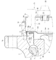
図1は、本発明に係る車輪用軸受装置の一実施形態を示す縦断面図、図2は、図1の検出部を示す要部拡大図、図3は、図1のドレーン部を示す要部拡大図、図4は、図1のキャップの嵌合部を示す要部拡大図、図5は、図1の車輪用軸受装置の変形例を示す要部拡大図、図6は、図1のキャップ嵌合部の変形例を示す要部拡大図、図7は、図1のキャップ嵌合部の他の変形例を示す要部拡大図、図8は、図1のキャップ嵌合部の他の変形例を示す要部拡大図である。なお、以下の説明では、車両に組み付けた状態で車両の外側寄りとなる側をアウター側(図1の左側)、中央寄り側をインナー側(図1の右側)という。
Hereinafter, embodiments of the present invention will be described in detail with reference to the drawings.
FIG. 1 is a longitudinal sectional view showing an embodiment of a wheel bearing device according to the present invention, FIG. 2 is an enlarged view of a main part showing a detection part of FIG. 1, and FIG. 3 is a main part showing a drain part of FIG. FIG. 4 is an enlarged view of a main part showing a fitting part of the cap of FIG. 1, FIG. 5 is an enlarged view of a main part showing a modification of the wheel bearing device of FIG. 1, and FIG. FIG. 7 is an enlarged view of a main part showing another modification of the cap fitting part of FIG. 1, and FIG. 8 is an enlarged view of the cap fitting part of FIG. It is a principal part enlarged view which shows another modification. In the following description, the side closer to the outer side of the vehicle when assembled to the vehicle is referred to as the outer side (left side in FIG. 1), and the side closer to the center is referred to as the inner side (right side in FIG. 1).
この車輪用軸受装置は従動輪側の第3世代と呼称され、内方部材1と外方部材2、および両部材1、2間に転動自在に収容された複列の転動体(ボール)3、3とを備えている。内方部材1は、ハブ輪4と、このハブ輪4に所定のシメシロを介して圧入された内輪5とからなる。
This wheel bearing device is called the third generation on the driven wheel side, and is a double row rolling element (ball) accommodated between the
ハブ輪4は、アウター側の端部に車輪(図示せず)を取り付けるための車輪取付フランジ6を一体に有し、外周に一方(アウター側)の内側転走面4aと、この内側転走面4aから軸方向に延びる小径段部4bが形成されている。車輪取付フランジ6にはハブボルト6aが周方向等配に植設されている。
The hub wheel 4 integrally has a wheel mounting flange 6 for mounting a wheel (not shown) at an end portion on the outer side, and has one (outer side)
内輪5は、外周に他方(インナー側)の内側転走面5aが形成され、ハブ輪4の小径段部4bに圧入されて背面合せタイプの複列アンギュラ玉軸受を構成すると共に、小径段部4bの端部を塑性変形させて形成した加締部4cによって内輪5が軸方向に固定されている。これにより、軽量・コンパクト化を図ることができる。なお、内輪5および転動体3、3はSUJ2等の高炭素クロム鋼で形成され、ズブ焼入れによって芯部まで58〜64HRCの範囲に硬化処理されている。
The
ハブ輪4はS53C等の炭素0.40〜0.80wt%を含む中高炭素鋼で形成され、内側転走面4aをはじめ、後述するシール8のシールランド部となる車輪取付フランジ6のインナー側の基部6bから小径段部4bに亙って高周波焼入れによって表面硬さを58〜64HRCの範囲に硬化処理されている。なお、加締部4cは鍛造加工後の表面硬さの生のままとされている。これにより、車輪取付フランジ6に負荷される回転曲げ荷重に対して充分な機械的強度を有し、内輪5の嵌合部となる小径段部4bの耐フレッティング性が向上すると共に、微小なクラック等の発生がなく加締部4cの塑性加工をスムーズに行うことができる。
The hub wheel 4 is made of medium and high carbon steel containing 0.40 to 0.80 wt% of carbon such as S53C, and includes an
外方部材2は、外周にナックル9に取り付けられるための車体取付フランジ2bを一体に有し、この車体取付フランジ2bのインナー側にナックル(図示せず)に嵌合される円筒状のパイロット部2cが形成され、内周に内方部材1の内側転走面4a、5aに対向する複列の外側転走面2a、2aが一体に形成されている。これら両転走面間に複列の転動体3、3が収容され、保持器7、7によって転動自在に保持されている。そして、外方部材2と内方部材1との間に形成される環状空間のアウター側の開口部にシール8が装着されると共に、インナー側の開口部には後述するキャップ14が装着され、軸受内部に封入されたグリースの外部への漏洩と、外部から雨水やダスト等が軸受内部に侵入するのを防止している。
The
外方部材2はS53C等の炭素0.40〜0.80wt%を含む中高炭素鋼で形成され、少なくとも複列の外側転走面2a、2aが高周波焼入れによって表面硬さを58〜64HRCの範囲に硬化処理されている。
The
シール8は、外方部材2のアウター側の端部内周に圧入された芯金9と、この芯金9に加硫接着によって一体に接合されたシール部材10とからなる一体型シールで構成されている。芯金9は、オーステナイト系ステンレス鋼板(JIS規格のSUS304系等)や冷間圧延鋼板(JIS規格のSPCC系等)からプレス加工にて断面が略L字状に形成されている。
The
一方、シール部材10はNBR等の合成ゴムからなり、径方向外方に傾斜して延び、断面が円弧状に形成された基部6bの外周面に所定の軸方向シメシロを介して摺接するサイドリップ10aとダストリップ10bおよび径方向内方に傾斜して延び、基部6bの外周面に所定の径方向シメシロを介して摺接するグリースリップ10cを有している。そして、芯金9の外表面を覆うように、シール部材10が回り込んで接合され、所謂ハーフメタル構造をなしている。これにより、気密性を高めて軸受内部を保護することができる。
On the other hand, the seal member 10 is made of a synthetic rubber such as NBR, and extends sideways in the radial direction. The side lip is slidably contacted with the outer peripheral surface of the
なお、シール部材10の材質としては、例示したNBR以外にも、例えば、耐熱性に優れたHNBR(水素化アクリロニトリル・ブタジエンゴム)、EPDM(エチレンプロピレンゴム)等をはじめ、耐熱性、耐薬品性に優れたACM(ポリアクリルゴム)、FKM(フッ素ゴム)、あるいはシリコンゴム等を例示することができる。 As the material of the seal member 10, in addition to the exemplified NBR, for example, HNBR (hydrogenated acrylonitrile butadiene rubber), EPDM (ethylene propylene rubber), etc. having excellent heat resistance, heat resistance, chemical resistance, etc. Examples thereof include ACM (polyacrylic rubber), FKM (fluororubber), and silicon rubber, which are excellent in the above.
なお、ここでは、転動体3、3にボールを使用した複列アンギュラ玉軸受で構成された車輪用軸受装置を例示したが、これに限らず、円錐ころを使用した複列円錐ころ軸受で構成されたものであっても良い。
In addition, although the wheel bearing apparatus comprised by the double row angular contact ball bearing which used the ball for the
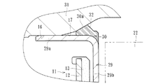
本実施形態では、内輪5の外周にパルサリング11が圧入されている。このパルサリング11は、図2に拡大して示すように、円環状に形成された支持環12と、この支持環12の側面に加硫接着等で一体に接合された磁気エンコーダ13とで構成されている。この磁気エンコーダ13は、ゴム等のエラストマにフェライト等の磁性体粉が混入され、周方向に交互に磁極N、Sが着磁されて車輪の回転速度検出用のロータリエンコーダを構成している。
In the present embodiment, the
支持環12は強磁性体の鋼板、例えば、フェライト系のステンレス鋼板(JIS規格のSUS430系等)や防錆処理された冷間圧延鋼板からプレス加工によって断面略L字状に形成され、内輪5に圧入される円筒部12aと、この円筒部12aから径方向外方に延びる立板部12bとを有している。そして、この立板部12bのインナー側の側面に磁気エンコーダ13が接合されている。
The
ここで、外方部材2にキャップ14が装着され、外方部材2のインナー側の開口部を閉塞している。このキャップ14は、耐食性を有し、後述する回転速度センサ22の感知性能に悪影響を及ぼさないように、非磁性体のオーステナイト系ステンレス鋼板からプレス加工によってカップ状に形成され、外方部材2のインナー側の端部内周に圧入される円筒状の嵌合部14aと、この嵌合部14aから縮径部14bを介して磁気エンコーダ13に僅かな軸方向すきまを介して対峙する円板部14cと、この円板部14cからアウター側に膨出する屈曲部14dを介して内方部材(図示せず)のインナー側の端部を覆う底部14eを備えている。
Here, the
キャップ14は、縮径部14bの外周面にNBR等の合成ゴムからなる弾性部材15が加硫接着によって一体に接合されている。この弾性部材15は、キャップ14の円板部14cの側面からインナー側に突出して回転速度センサ22に干渉しないように接合され、嵌合部14aの外径より径方向外方に突出する環状突起15aを備えている。
In the
外方部材2の端部内周には、図4に拡大して示すように、キャップ14の嵌合部14aが圧入される内側嵌合面16と、この内側嵌合面16からインナー側にテーパ状の段部17を介して内側嵌合面16よりも大径の逃げ面18が形成されている。そして、外方部材2の内側嵌合面16がビビリ高さ3μm以下に規制されると共に、弾性部材15の環状突起15aがキャップ14の嵌合時に外方部材2の逃げ面18に弾性変形して圧着され、嵌合部14aの気密性を高めている。
As shown in an enlarged view in FIG. 4, an inner
本実施形態では、外方部材2の端部内周が、内側嵌合面16と、この内側嵌合面16から段部17を介してインナー側に形成された逃げ面18とで構成され、内側嵌合面16にキャップ14の嵌合部14aが圧入されると共に、内側嵌合面16より大径の逃げ面18に弾性部材15が圧入されるので、キャップ14の嵌合時、例えば、キャップ14の嵌合部14aによって外方部材2の内側嵌合面16にスリット状の圧入傷がついても、この部位は圧入嵌合とならず、環状突起15aによって外方部材2の内側嵌合面16にスリット状の圧入傷が付くのを防止することができると共に、環状突起15aが部分的に潰れて損傷するのを防止し、キャップ14の嵌合部14aの気密性を高めて信頼性の向上を図った車輪用軸受装置を提供することができる。
In the present embodiment, the inner periphery of the end portion of the
前述した逃げ面18の内径Drは内側嵌合面16の内径Dsよりも大径に形成されるが、具体的には、逃げ面18の内径Drは内側嵌合面16の内径Dsの公差最大値よりも大径になるように設定されている。これにより、キャップ14の嵌合部14aと弾性部材15の圧入面が同一径ではなく径差が設けられるため、キャップ14の嵌合時、環状突起15aによって外方部材2の内側嵌合面16にスリット状の圧入傷が付くのを確実に防止することができる。
The aforementioned inner diameter Dr of the
本実施形態では、図2に示すように、キャップ14のインナー側に、さらにセンサキャップ19が装着されている。具体的には、外方部材2の逃げ面18の開口部側(インナー側)に所定の段差を介して外側嵌合面20が形成され、センサキャップ19はこの外側嵌合面20に所定のシメシロを介して圧入されている。この外側嵌合面20は、複列の外側転走面2a、2aと、キャップ14が圧入される内側嵌合面16と総型砥石によって同時研削されている。これにより、キャップ14の圧入ストロークを最小限に抑えて組立作業性が向上すると共に、各嵌合面16、20の真円度や同軸度等の精度が向上し、各嵌合部の気密性が高くなる。また、同時研削によって加工工数を低減することができ、低コスト化を図ることができる。
In the present embodiment, as shown in FIG. 2, a
このセンサキャップ19は防錆処理された冷間圧延鋼板からプレス加工によってカップ状に形成され、外方部材2のインナー側の端部内周に圧入される円筒状の嵌合部19aと、この嵌合部19aから径方向外方に重合して延び、外方部材2のインナー側の端面2dに密着する鍔部19bと、この鍔部19bから外方部材2のインナー側の開口部を閉塞する底部19cとを備えている。このセンサキャップ19の底部19cには磁気エンコーダ13に対応する水平位置に嵌挿孔21が形成され、この嵌挿孔21に回転速度センサ22が嵌挿される。
The
このように、センサキャップ19が外方部材2の端面2dに密着する鍔部19bを備えているので、剛性を高めて回転速度センサの位置決め精度を向上させることができると共に、嵌挿孔21が水平位置に形成され、この嵌挿孔21に回転速度センサ22が装着されていれば、車輪からの横方向荷重により外方部材2と内方部材1が相対的に傾いた状態においても、回転速度センサ22と磁気エンコーダ13とのエアギャップ変動を抑制することができ、安定した検出精度を得ることができる。
Thus, since the
また、外側キャップ19の中心部に形成された穿孔23に、底部19cの軸受内方側(アウター側)に固定ナット24が加締加工により固定されている。固定ナット24の固定方法は、これ以外にも、例えば、溶接、接着、圧入等であっても良い。そして、センサキャップ19の嵌挿孔21に嵌挿された回転速度センサ22が、取付部材25を介して取付ボルト26を固定ナット24に締結することによって固定されている。このように、取付ボルト26の締結により固定ナット24が底部19cの内側面に引き込まれるため、固定ナット24の加締だけで脱落を防止することができる。
In addition, a fixing
回転速度センサ22は、ホール素子、磁気抵抗素子(MR素子)等、磁束の流れ方向に応じて特性を変化させる磁気検出素子およびこの磁気検出素子の出力波形を整える波形整形回路が組み込まれたIC等からなり、車輪の回転速度を検出してその回転数を制御する自動車のアンチロックブレーキシステムを構成している。そして、この回転速度センサ22がキャップ14の円板部14cに衝合または近接するまで挿入されている。これにより、所望のエアギャップが得られ、煩雑なエアギャップ調整を省いて組立作業性の向上が図れると共に、縮径部14bに合成ゴムからなる弾性部材15が設けられたキャップ14により軸受内部を密封することができ、密封性の向上を図った車輪用軸受装置を提供することができる。
The
センサキャップ19にはカチオン電着塗装によって防錆皮膜が形成されている。なお、カチオン電着塗装は、正電極に対して、製品側を負電極として通電するものであるが、負電極に対して、製品側を正電極として通電するアニオン型の電着塗装であっても良い。このアニオン型の電着塗装の場合、塗装色の安定性や焼付温度を低く設定できる特徴を備えているが、この種のセンサキャップ19においては、防錆力と密着力に優れた強力な塗装膜が形成できるエポキシ樹脂系等からなるカチオン電着塗装の方が好ましい。
A rust preventive film is formed on the
このように、本実施形態では、センサキャップ19にカチオン電着塗装からなる防錆皮膜が形成されているので、センサキャップ19の嵌合部19aが長期間に亘って発錆するのを防止することができ、外方部材2の外側嵌合面20および端面2dとの間で良好な気密性が得られる。
Thus, in this embodiment, since the rust prevention film which consists of cationic electrodeposition coating is formed in the
なお、前述したシール8においても、図示しないが、芯金9の嵌合部にシール部材10が回り込むハーフメタル構造においても、外方部材2のアウター側の端部内周に嵌合面と、この嵌合面から段部を介して嵌合面よりも大径の逃げ面を設け、この逃げ面にシール部材10の一部を圧着させるようにしても良い。
Even in the above-described
また、本実施形態では、図3に示すように、センサキャップ19の底部19cの径方向外方側にドレーン27が形成されている。このドレーン27は、嵌合部19aと底部19cの路面に近い側の膨出部28に形成されている。膨出部28は、底部19bからインナー側に所定の寸法Lだけ突出して形成されている。この膨出部28は、ナックル(図示せず)が外方部材2の端面2dと面一ではなく、インナー側に突出している場合に有効である。すなわち、センサキャップ19の膨出部28にドレーン27を径方向に貫通して形成することにより、センサキャップ19内に外部から雨水等の異物が浸入したとしても、この膨出部28部分に流動落下し、ナックルに妨害されることなく容易に異物を外部に効果的に排出することができる。
In the present embodiment, as shown in FIG. 3, a
前述した実施形態では、キャップ14のインナー側にセンサキャップ19が装着された、所謂二重キャップ構造を例示したが、これに限らず、外方部材の端部内周に単一のキャップを装着した構造でも良い。すなわち、図5に示すように、外方部材2’の端部内周に、キャップ14の嵌合部14aが圧入される嵌合面16’と、この嵌合面16’からインナー側にテーパ状の段部17’を介して嵌合面16’より大径の逃げ面18’が形成されている。そして、弾性部材15の環状突起15aがキャップ14の嵌合時に外方部材2’の逃げ面18’に弾性変形して圧着され、嵌合部14aの気密性を高めている。
In the above-described embodiment, the so-called double cap structure in which the
このように、外方部材2’の端部内周が、嵌合面16’と、この嵌合面16’から段部17’を介してインナー側に形成された逃げ面18’とで構成され、嵌合面16’にキャップ14の嵌合部14aが圧入されると共に、嵌合面16’より大径の逃げ面18’に弾性部材15が圧入されるので、キャップ14の嵌合時、環状突起15aによって外方部材2’の嵌合面16’にスリット状の圧入傷が付くのを防止することができると共に、環状突起15aが部分的に潰れて損傷するのを防止し、キャップ14の嵌合部14aの気密性を高めて信頼性の向上を図ることができる。
As described above, the inner periphery of the end portion of the
図6にキャップ嵌合部の変形例を示す。このキャップ29は、耐食性を有し、回転速度センサ22の感知性能に悪影響を及ぼさないように、非磁性体のオーステナイト系ステンレス鋼板からプレス加工によってカップ状に形成され、外方部材2のインナー側の端部内周に圧入される円筒状の嵌合部29aと、この嵌合部29aから磁気エンコーダ13に僅かな軸方向すきまを介して対峙する円板部29bを備えている。
FIG. 6 shows a modification of the cap fitting portion. The
キャップ29は、嵌合部29aの外周面にNBR等の合成ゴムからなる弾性部材30が加硫接着によって一体に接合されている。この弾性部材30は、キャップ29の円板部29bの側面からインナー側に突出して回転速度センサ22に干渉しないように接合され、嵌合部29aの外径より径方向外方に突出し、テーパ面を有する環状突起30aを備えている。
In the
外方部材31の端部内周には、キャップ29の嵌合部29aが圧入される内側嵌合面16と、この内側嵌合面16からインナー側にテーパ状の段部17を介して開口側に向って漸次拡径するテーパ状の逃げ面32が形成されている。そして、弾性部材30の環状突起30aがキャップ29の嵌合時に外方部材31の逃げ面32に弾性変形して圧着されている。本実施形態では、テーパ面を有する環状突起30aが外方部材31の逃げ面32に楔状に食い込んで圧着されるので、嵌合部29aの気密性を一層高めることができる。
An inner
図7にキャップ嵌合部の他の変形例で、前述したキャップ29の弾性部材30の構成が異なる。このキャップ29は、外方部材2のインナー側の端部内周に圧入される円筒状の嵌合部29aと、この嵌合部29aから磁気エンコーダ13に僅かな軸方向すきまを介して対峙する円板部29bを備えている。そして、嵌合部29aの外周面にNBR等の合成ゴムからなる弾性部材33が加硫接着によって一体に接合されている。
FIG. 7 shows another modification of the cap fitting portion, and the configuration of the
この弾性部材33は、円板部29bの側面からインナー側に突出して回転速度センサ22に干渉しないように接合され、弾性部材33がキャップ29の嵌合時に外方部材2の逃げ面18に弾性変形して圧着されている。本実施形態では、前述した環状突起が外方部材2の逃げ面18に圧着されるのではなく、弾性部材33の外周面全体が圧着されるので、嵌合部29aの気密性を一層高めることができる。
The
図8にキャップ嵌合部の他の変形例で、前述したキャップ29の弾性部材30の構成が異なる。このキャップ29は、外方部材2のインナー側の端部内周に圧入される円筒状の嵌合部29aと、この嵌合部29aから磁気エンコーダ13に僅かな軸方向すきまを介して対峙する円板部29bを備えている。そして、嵌合部29aの外周面にNBR等の合成ゴムからなる弾性部材34が加硫接着によって一体に接合されている。
FIG. 8 shows another modification of the cap fitting portion, and the configuration of the
この弾性部材34は、円板部29bの側面からインナー側に突出して回転速度センサ22に干渉しないように接合され、弾性部材33がキャップ29の嵌合時に外方部材2の段部17と逃げ面18に弾性変形して圧着されている。これにより、弾性部材33が外方部材2とキャップ29との嵌合すきまを充足して圧着されるので、嵌合部29aの気密性を一層高めることができる。
The elastic member 34 protrudes inward from the side surface of the
以上、本発明の実施の形態について説明を行ったが、本発明はこうした実施の形態に何等限定されるものではなく、あくまで例示であって、本発明の要旨を逸脱しない範囲内において、さらに種々なる形態で実施し得ることは勿論のことであり、本発明の範囲は、特許請求の範囲の記載によって示され、さらに特許請求の範囲に記載の均等の意味、および範囲内のすべての変更を含む。 The embodiment of the present invention has been described above, but the present invention is not limited to such an embodiment, and is merely an example, and various modifications can be made without departing from the scope of the present invention. Of course, the scope of the present invention is indicated by the description of the scope of claims, and further, the equivalent meanings described in the scope of claims and all modifications within the scope of the scope of the present invention are included. Including.
本発明に係る車輪用軸受装置は、従動輪用で、転動体がボール、円錐ころ等、あらゆる構造の内輪回転タイプで、外方部材のインナー側の端部にキャップが装着された車輪用軸受装置に適用することができる。 The wheel bearing device according to the present invention is a wheel bearing for a driven wheel, in which the rolling element is an inner ring rotating type of any structure such as a ball and a tapered roller, and a cap is mounted on the inner side end of the outer member. It can be applied to the device.
1 内方部材
2、2’、31 外方部材
2a 外側転走面
2b 車体取付フランジ
2c パイロット部
2d 外方部材のインナー側の端面
3 転動体
4 ハブ輪
4a、5a 内側転走面
4b 小径段部
4c 加締部
5 内輪
6 車輪取付フランジ
6a ハブボルト
6b 車輪取付フランジのインナー側の基部
7 保持器
8 シール
9 芯金
10 シール部材
10a サイドリップ
10b ダストリップ
10c グリースリップ
11 パルサリング
12 支持環
12a 円筒部
12b 立板部
13 磁気エンコーダ
14、29 キャップ
14a、19a、29a 嵌合部
14b 縮径部
14c、29b 円板部
14d 屈曲部
14e 底部
15、30、33、34 弾性部材
15a、30a 環状突起
16 内側嵌合面
16’ 嵌合面
17、17’ 段部
18、18’、32 逃げ面
19 センサキャップ
19b 鍔部
19c 底部
20 外側嵌合面
21 嵌挿孔
22 回転速度センサ
23 穿孔
24 固定ナット
25 取付部材
26 取付ボルト
27 ドレーン
28 膨出部
51 内方部材
52 外方部材
52a、52b 外側転走面
52c 車体取付フランジ
53a、53b ボール
54 ハブ輪
54a、55a 内側転走面
54b 小径段部
54c 加締部
54d 軸状部
55 内輪
56 車輪取付フランジ
57 シール
58 センサキャップ
58a 嵌合部
58b 縮径部
58c 底部
59 パルサリング
60 支持環
61 磁気エンコーダ
62 弾性部材
62a 環状突起
63 回転速度センサ
64 円形凹所
65 固定ナット
65a 雌ねじ
Ds 内側嵌合面の内径
Dr 逃げ面の内径
L 膨出部の底部からの突出量
PCDi 反車輪取付フランジ側のボール列のピッチ円直径
PCDo 車輪取付フランジ側のボール列のピッチ円直径
di 反車輪取付フランジ側のボール列のボール径
do 車輪取付フランジ側のボール列のボール径
Zi 反車輪取付フランジ側のボール列のボール数
Zo 車輪取付フランジ側のボール列のボール数
DESCRIPTION OF SYMBOLS 1 Inner member 2, 2 ', 31 Outer member 2a Outer rolling surface 2b Car body mounting flange 2c Pilot part 2d Outer member inner side end surface 3 Rolling element 4 Hub wheel 4a, 5a Inner rolling surface 4b Small diameter step Part 4c Caulking part 5 Inner ring 6 Wheel mounting flange 6a Hub bolt 6b Base part on inner side of wheel mounting flange 7 Cage 8 Seal 9 Core 10 Seal member 10a Side lip 10b Dustrip 10c Grease lip 11 Pulsar ring 12 Support ring 12a Cylindrical part 12b Standing plate portion 13 Magnetic encoder 14, 29 Cap 14a, 19a, 29a Fitting portion 14b Reduced diameter portion 14c, 29b Disc portion 14d Bending portion 14e Bottom portion 15, 30, 33, 34 Elastic member 15a, 30a Annular protrusion 16 Inside Fitting surface 16 'Fitting surface 17, 17' Stepped portion 18, 18 ', 32 Flank 19 Sensor cap 1 b flange 19c bottom 20 outer fitting surface 21 fitting insertion hole 22 rotational speed sensor 23 perforation 24 fixing nut 25 mounting member 26 mounting bolt 27 drain 28 bulging portion 51 inner member 52 outer members 52a and 52b outer rolling surface 52c Car body mounting flange 53a, 53b Ball 54 Hub wheel 54a, 55a Inner rolling surface 54b Small diameter step 54c Clamping portion 54d Shaft portion 55 Inner ring 56 Wheel mounting flange 57 Seal 58 Sensor cap 58a Fitting portion 58b Reduced diameter portion 58c Bottom 59 Pulsar ring 60 Support ring 61 Magnetic encoder 62 Elastic member 62a Annular protrusion 63 Rotational speed sensor 64 Circular recess 65 Fixing nut 65a Female thread Ds Inner fitting surface inner diameter Dr Escape surface inner diameter L Amount of protrusion from the bottom of the bulging portion PCDi Pitch circle diameter of the row of balls on the anti-wheel mounting flange side PCDo Pitch circle diameter di of the ball row on the lunge side Ball diameter of the ball row on the anti-wheel mounting flange side ball diameter Zi of the ball row on the wheel mounting flange side Zi Number of balls in the ball row on the anti-wheel mounting flange side Zo On the wheel mounting flange side Number of balls in the ball row
Claims (5)
一端部に車輪を取り付けるための車輪取付フランジを一体に有し、外周に軸方向に延びる小径段部が形成されたハブ輪、およびこのハブ輪の小径段部に圧入された少なくとも一つの内輪とからなり、外周に前記複列の外側転走面に対向する複列の内側転走面が形成された内方部材と、
前記外方部材と内方部材のそれぞれの転走面間に転動自在に収容された複列の転動体と、
前記外方部材と内方部材との間に形成される環状空間の開口部のうちアウター側の開口部に装着されたシールと、
インナー側の開口部に装着されたキャップと、を備え、このキャップが、前記外方部材の内側嵌合面に圧入される円筒状の嵌合部と、この嵌合部から径方向内方に延び、前記内方部材のインナー側の端部を覆う底部を備え、前記嵌合部のインナー側の端部外周に合成ゴムからなる弾性部材が加硫接着により一体に接合され、この弾性部材が前記嵌合部の外径よりも径方向外方に突出して形成された車輪用軸受装置において、
前記外方部材のインナー側の端部内周が、前記キャップが圧入される内側嵌合面と、この内側嵌合面から段部を介してインナー側に形成され、前記内側嵌合面よりも大径の逃げ面とで構成されると共に、
前記逃げ面が開口側に向って漸次拡径するテーパ状に形成され、前記弾性部材が弾性変形して当該逃げ面に圧着されるテーパ面を有していることを特徴とする車輪用軸受装置。 An outer member integrally having a vehicle body mounting flange for being attached to the vehicle body on the outer periphery, and an outer rolling surface of a double row integrally formed on the inner periphery;
A hub wheel integrally having a wheel mounting flange for mounting a wheel at one end, and having a small-diameter step portion extending in the axial direction on the outer periphery, and at least one inner ring press-fitted into the small-diameter step portion of the hub ring; An inner member in which a double row inner rolling surface facing the outer rolling surface of the double row is formed on the outer periphery,
A double row rolling element accommodated in a freely rolling manner between the rolling surfaces of the outer member and the inner member;
A seal attached to an opening on the outer side of the opening of the annular space formed between the outer member and the inner member;
A cap attached to the opening on the inner side, and the cap is a cylindrical fitting portion press-fitted into the inner fitting surface of the outer member, and radially inward from the fitting portion. An elastic member made of synthetic rubber is integrally joined to the outer periphery of the inner side end of the fitting portion by vulcanization bonding , and includes a bottom portion that covers the inner side end of the inner member. In the wheel bearing device formed to protrude radially outward from the outer diameter of the fitting portion,
The inner periphery of the outer member on the inner side is formed with an inner fitting surface into which the cap is press-fitted and an inner side through a step portion from the inner fitting surface, and is larger than the inner fitting surface. It is composed of a flank with a diameter,
The wheel bearing device, wherein the flank is formed in a tapered shape that gradually increases in diameter toward the opening side, and the elastic member has a tapered surface that is elastically deformed and pressure-bonded to the flank. .
Priority Applications (5)
| Application Number | Priority Date | Filing Date | Title |
|---|---|---|---|
| JP2013067578A JP6239842B2 (en) | 2013-03-27 | 2013-03-27 | Wheel bearing device |
| PCT/JP2014/058905 WO2014157537A1 (en) | 2013-03-27 | 2014-03-27 | Wheel bearing device |
| CN201480017903.9A CN105121878B (en) | 2013-03-27 | 2014-03-27 | Wheel bearing arrangement |
| EP14775738.9A EP2980432B1 (en) | 2013-03-27 | 2014-03-27 | Wheel bearing device |
| US14/865,043 US10081218B2 (en) | 2013-03-27 | 2015-09-25 | Wheel bearing apparatus |
Applications Claiming Priority (1)
| Application Number | Priority Date | Filing Date | Title |
|---|---|---|---|
| JP2013067578A JP6239842B2 (en) | 2013-03-27 | 2013-03-27 | Wheel bearing device |
Publications (2)
| Publication Number | Publication Date |
|---|---|
| JP2014190462A JP2014190462A (en) | 2014-10-06 |
| JP6239842B2 true JP6239842B2 (en) | 2017-11-29 |
Family
ID=51836917
Family Applications (1)
| Application Number | Title | Priority Date | Filing Date |
|---|---|---|---|
| JP2013067578A Active JP6239842B2 (en) | 2013-03-27 | 2013-03-27 | Wheel bearing device |
Country Status (1)
| Country | Link |
|---|---|
| JP (1) | JP6239842B2 (en) |
Families Citing this family (2)
| Publication number | Priority date | Publication date | Assignee | Title |
|---|---|---|---|---|
| JP6759918B2 (en) * | 2016-09-16 | 2020-09-23 | 株式会社ジェイテクト | How to manufacture the hub unit |
| DE102020101196A1 (en) * | 2019-11-08 | 2021-05-12 | Schaeffler Technologies AG & Co. KG | Wheel bearing unit for a vehicle |
Family Cites Families (2)
| Publication number | Priority date | Publication date | Assignee | Title |
|---|---|---|---|---|
| JP3636201B1 (en) * | 2004-02-04 | 2005-04-06 | 日本精工株式会社 | Rolling bearing unit with rotational speed detector |
| JP5894389B2 (en) * | 2011-07-28 | 2016-03-30 | Ntn株式会社 | Wheel bearing device |
-
2013
- 2013-03-27 JP JP2013067578A patent/JP6239842B2/en active Active
Also Published As
| Publication number | Publication date |
|---|---|
| JP2014190462A (en) | 2014-10-06 |
Similar Documents
| Publication | Publication Date | Title |
|---|---|---|
| JP5616758B2 (en) | Wheel bearing device with rotation speed detector | |
| WO2014157537A1 (en) | Wheel bearing device | |
| JP5331640B2 (en) | Wheel bearing device with rotation speed detector | |
| JP5334823B2 (en) | Wheel bearing device with rotation speed detector | |
| WO2011115252A1 (en) | Wheel bearing device equipped with rotational speed detector | |
| US7255014B2 (en) | Wheel bearing apparatus incorporated with a wheel speed detecting apparatus | |
| US7618194B2 (en) | Wheel bearing apparatus incorporated with a wheel speed detecting apparatus | |
| WO2017150562A1 (en) | Bearing device for vehicle wheel | |
| JP4628049B2 (en) | Wheel bearing device with rotation speed detector | |
| JP6239842B2 (en) | Wheel bearing device | |
| JP2008019912A (en) | Wheel bearing device | |
| JP5914090B2 (en) | Wheel bearing device | |
| JP6290543B2 (en) | Wheel bearing device | |
| JP5914077B2 (en) | Wheel bearing device | |
| JP5914213B2 (en) | Wheel bearing device | |
| JP2016078512A (en) | Bearing device for wheel | |
| JP6239920B2 (en) | Wheel bearing device | |
| JP4628395B2 (en) | Wheel bearing device with rotation speed detector | |
| JP2008180544A (en) | Bearing device for wheel with revolution detector | |
| JP5914082B2 (en) | Wheel bearing device | |
| JP5914086B2 (en) | Wheel bearing device | |
| JP2018035943A (en) | Bearing device for wheel | |
| JP6298262B2 (en) | Wheel bearing device | |
| JP5213464B2 (en) | Wheel bearing device with rotation speed detector | |
| JP6320092B2 (en) | Wheel bearing device |
Legal Events
| Date | Code | Title | Description |
|---|---|---|---|
| A621 | Written request for application examination |
Free format text: JAPANESE INTERMEDIATE CODE: A621 Effective date: 20150917 |
|
| A131 | Notification of reasons for refusal |
Free format text: JAPANESE INTERMEDIATE CODE: A131 Effective date: 20160725 |
|
| A521 | Request for written amendment filed |
Free format text: JAPANESE INTERMEDIATE CODE: A523 Effective date: 20160921 |
|
| A131 | Notification of reasons for refusal |
Free format text: JAPANESE INTERMEDIATE CODE: A131 Effective date: 20170308 |
|
| A521 | Request for written amendment filed |
Free format text: JAPANESE INTERMEDIATE CODE: A523 Effective date: 20170502 |
|
| TRDD | Decision of grant or rejection written | ||
| A01 | Written decision to grant a patent or to grant a registration (utility model) |
Free format text: JAPANESE INTERMEDIATE CODE: A01 Effective date: 20171013 |
|
| A61 | First payment of annual fees (during grant procedure) |
Free format text: JAPANESE INTERMEDIATE CODE: A61 Effective date: 20171102 |
|
| R150 | Certificate of patent or registration of utility model |
Ref document number: 6239842 Country of ref document: JP Free format text: JAPANESE INTERMEDIATE CODE: R150 |
|
| R250 | Receipt of annual fees |
Free format text: JAPANESE INTERMEDIATE CODE: R250 |
|
| R250 | Receipt of annual fees |
Free format text: JAPANESE INTERMEDIATE CODE: R250 |
|
| R250 | Receipt of annual fees |
Free format text: JAPANESE INTERMEDIATE CODE: R250 |
|
| R250 | Receipt of annual fees |
Free format text: JAPANESE INTERMEDIATE CODE: R250 |