JP5334823B2 - Wheel bearing device with rotation speed detector - Google Patents
Wheel bearing device with rotation speed detector Download PDFInfo
- Publication number
- JP5334823B2 JP5334823B2 JP2009277963A JP2009277963A JP5334823B2 JP 5334823 B2 JP5334823 B2 JP 5334823B2 JP 2009277963 A JP2009277963 A JP 2009277963A JP 2009277963 A JP2009277963 A JP 2009277963A JP 5334823 B2 JP5334823 B2 JP 5334823B2
- Authority
- JP
- Japan
- Prior art keywords
- cap
- rotational speed
- wheel bearing
- bearing device
- sensor
- Prior art date
- Legal status (The legal status is an assumption and is not a legal conclusion. Google has not performed a legal analysis and makes no representation as to the accuracy of the status listed.)
- Active
Links
- 238000005096 rolling process Methods 0.000 claims description 100
- 238000001514 detection method Methods 0.000 claims description 41
- 230000005291 magnetic effect Effects 0.000 claims description 38
- 229910000831 Steel Inorganic materials 0.000 claims description 13
- 239000010959 steel Substances 0.000 claims description 13
- 229920003051 synthetic elastomer Polymers 0.000 claims description 13
- 239000005061 synthetic rubber Substances 0.000 claims description 13
- 238000003780 insertion Methods 0.000 claims description 12
- 230000037431 insertion Effects 0.000 claims description 12
- 229910000963 austenitic stainless steel Inorganic materials 0.000 claims description 8
- 238000003825 pressing Methods 0.000 claims description 8
- 230000002093 peripheral effect Effects 0.000 claims description 7
- 125000002091 cationic group Chemical group 0.000 claims description 5
- 239000011248 coating agent Substances 0.000 claims description 5
- 238000000576 coating method Methods 0.000 claims description 5
- 238000004070 electrodeposition Methods 0.000 claims description 5
- JEIPFZHSYJVQDO-UHFFFAOYSA-N iron(III) oxide Inorganic materials O=[Fe]O[Fe]=O JEIPFZHSYJVQDO-UHFFFAOYSA-N 0.000 claims description 5
- 230000002265 prevention Effects 0.000 claims description 5
- 229910001220 stainless steel Inorganic materials 0.000 claims description 3
- 238000004073 vulcanization Methods 0.000 claims description 3
- 239000010935 stainless steel Substances 0.000 claims description 2
- 230000007797 corrosion Effects 0.000 description 9
- 238000005260 corrosion Methods 0.000 description 9
- 239000002184 metal Substances 0.000 description 9
- 229910052751 metal Inorganic materials 0.000 description 9
- 238000007789 sealing Methods 0.000 description 9
- 239000010960 cold rolled steel Substances 0.000 description 5
- 230000004048 modification Effects 0.000 description 5
- 238000012986 modification Methods 0.000 description 5
- 229920001971 elastomer Polymers 0.000 description 4
- 239000000126 substance Substances 0.000 description 4
- OKTJSMMVPCPJKN-UHFFFAOYSA-N Carbon Chemical compound [C] OKTJSMMVPCPJKN-UHFFFAOYSA-N 0.000 description 3
- 230000002411 adverse Effects 0.000 description 3
- 229910052799 carbon Inorganic materials 0.000 description 3
- 239000005060 rubber Substances 0.000 description 3
- 239000000725 suspension Substances 0.000 description 3
- 229910000677 High-carbon steel Inorganic materials 0.000 description 2
- 229910000954 Medium-carbon steel Inorganic materials 0.000 description 2
- 229920000459 Nitrile rubber Polymers 0.000 description 2
- -1 S53C Chemical compound 0.000 description 2
- 238000005452 bending Methods 0.000 description 2
- 230000008859 change Effects 0.000 description 2
- 239000000428 dust Substances 0.000 description 2
- 238000005242 forging Methods 0.000 description 2
- 239000004519 grease Substances 0.000 description 2
- 230000006698 induction Effects 0.000 description 2
- 239000004033 plastic Substances 0.000 description 2
- 102220097517 rs876659265 Human genes 0.000 description 2
- 229920003002 synthetic resin Polymers 0.000 description 2
- 239000000057 synthetic resin Substances 0.000 description 2
- 229910000859 α-Fe Inorganic materials 0.000 description 2
- 229910000669 Chrome steel Inorganic materials 0.000 description 1
- HCHKCACWOHOZIP-UHFFFAOYSA-N Zinc Chemical compound [Zn] HCHKCACWOHOZIP-UHFFFAOYSA-N 0.000 description 1
- 238000013459 approach Methods 0.000 description 1
- 230000007423 decrease Effects 0.000 description 1
- 239000000806 elastomer Substances 0.000 description 1
- 210000004709 eyebrow Anatomy 0.000 description 1
- 210000000887 face Anatomy 0.000 description 1
- 230000005294 ferromagnetic effect Effects 0.000 description 1
- 230000004907 flux Effects 0.000 description 1
- 230000006872 improvement Effects 0.000 description 1
- 230000001050 lubricating effect Effects 0.000 description 1
- 239000006247 magnetic powder Substances 0.000 description 1
- 238000000465 moulding Methods 0.000 description 1
- 238000007747 plating Methods 0.000 description 1
- 239000000843 powder Substances 0.000 description 1
- 238000010791 quenching Methods 0.000 description 1
- 230000000171 quenching effect Effects 0.000 description 1
- 238000007493 shaping process Methods 0.000 description 1
- 230000035939 shock Effects 0.000 description 1
- 238000005549 size reduction Methods 0.000 description 1
- 239000013585 weight reducing agent Substances 0.000 description 1
- 239000011701 zinc Substances 0.000 description 1
- 229910052725 zinc Inorganic materials 0.000 description 1
Images


Classifications
-
- B—PERFORMING OPERATIONS; TRANSPORTING
- B60—VEHICLES IN GENERAL
- B60B—VEHICLE WHEELS; CASTORS; AXLES FOR WHEELS OR CASTORS; INCREASING WHEEL ADHESION
- B60B7/00—Wheel cover discs, rings, or the like, for ornamenting, protecting, venting, or obscuring, wholly or in part, the wheel body, rim, hub, or tyre sidewall, e.g. wheel cover discs, wheel cover discs with cooling fins
- B60B7/0013—Hub caps
-
- B—PERFORMING OPERATIONS; TRANSPORTING
- B60—VEHICLES IN GENERAL
- B60B—VEHICLE WHEELS; CASTORS; AXLES FOR WHEELS OR CASTORS; INCREASING WHEEL ADHESION
- B60B27/00—Hubs
- B60B27/0047—Hubs characterised by functional integration of other elements
- B60B27/0068—Hubs characterised by functional integration of other elements the element being a sensor
-
- B—PERFORMING OPERATIONS; TRANSPORTING
- B60—VEHICLES IN GENERAL
- B60B—VEHICLE WHEELS; CASTORS; AXLES FOR WHEELS OR CASTORS; INCREASING WHEEL ADHESION
- B60B27/00—Hubs
- B60B27/0073—Hubs characterised by sealing means
Landscapes
- Engineering & Computer Science (AREA)
- Mechanical Engineering (AREA)
- Rolling Contact Bearings (AREA)
Description
本発明は、自動車等の車輪を懸架装置に対して回転自在に支承する車輪用軸受装置、特に、車輪の回転速度を検出する回転速度検出装置が内蔵され、密封性の向上を図った回転速度検出装置付き車輪用軸受装置に関するものである。 The present invention relates to a wheel bearing device for rotatably supporting a wheel of an automobile or the like with respect to a suspension device, in particular, a rotation speed detection device for detecting the rotation speed of the wheel, and a rotation speed for improving the sealing performance. The present invention relates to a wheel bearing device with a detection device.
自動車の車輪を懸架装置に対して回転自在に支承すると共に、アンチロックブレーキシステム(ABS)を制御し、車輪の回転速度を検出する回転速度検出装置が内蔵された回転速度検出装置付き車輪用軸受装置が一般的に知られている。従来、このような車輪用軸受装置は、転動体を介して転接する内方部材および外方部材の間にシール装置が設けられ、円周方向に磁極を交互に並べてなる磁気エンコーダを前記シール装置に一体化させると共に、磁気エンコーダと、この磁気エンコーダに対面配置され、車輪の回転に伴う磁気エンコーダの磁極変化を検出する回転速度センサとで回転速度検出装置が構成されている。 A wheel bearing with a rotation speed detecting device that rotatably supports a vehicle wheel with respect to a suspension device and controls an anti-lock brake system (ABS) to detect the rotation speed of the wheel. Devices are generally known. Conventionally, in such a wheel bearing device, a sealing device is provided between an inner member and an outer member that are in rolling contact with a rolling element, and a magnetic encoder in which magnetic poles are alternately arranged in a circumferential direction is provided as the sealing device. In addition, the rotational speed detecting device is constituted by a magnetic encoder and a rotational speed sensor that is arranged facing the magnetic encoder and detects a magnetic pole change of the magnetic encoder accompanying the rotation of the wheel.
前記回転速度センサは、懸架装置を構成するナックルに車輪用軸受装置が装着された後、当該ナックルに装着されているものが一般的である。しかし、この回転速度センサと磁気エンコーダとのエアギャップの調整作業の煩雑さを解消すると共に、よりコンパクト化を狙って、最近では回転速度センサをも軸受に内蔵した回転速度検出装置付き車輪用軸受装置が提案されている。 In general, the rotational speed sensor is attached to the knuckle after the wheel bearing device is attached to the knuckle constituting the suspension device. However, in order to eliminate the complexity of adjusting the air gap between the rotational speed sensor and the magnetic encoder and to achieve a more compact design, recently, a bearing for a wheel with a rotational speed detection device that also incorporates the rotational speed sensor in the bearing. A device has been proposed.
このような回転速度検出装置付き車輪用軸受装置の一例として図11に示すような構造が知られている。この回転速度検出装置付き車輪用軸受装置は、図示しないナックルに支持固定され、固定部材となる外方部材51と、この外方部材51に複列のボール53、53を介して内挿された内方部材52とを有している。内方部材52は、ハブ輪55と、このハブ輪55に外嵌された内輪56とからなる。
A structure as shown in FIG. 11 is known as an example of such a wheel bearing device with a rotational speed detection device. This wheel bearing device with a rotational speed detection device is supported and fixed to a knuckle (not shown), and is inserted into the
外方部材51は、外周に車体取付フランジ51bを一体に有し、内周には複列の外側転走面51a、51aが形成されている。一方、内方部材52は、前記した外方部材51の外側転走面51a、51aに対向する複列の内側転走面55a、56aが形成されている。これら複列の内側転走面55a、56aのうち一方の内側転走面55aはハブ輪55の外周に一体形成され、他方の内側転走面56aは内輪56の外周に形成されている。この内輪56は、ハブ輪55の内側転走面55aから軸方向に延びる軸状の小径段部55bに圧入されている。そして、複列のボール53、53がこれら両転走面間にそれぞれ収容され、保持器57、57によって転動自在に保持されている。
The
ハブ輪55は、外周に車輪(図示せず)を取り付けるための車輪取付フランジ54を一体に有し、小径段部55bの端部を径方向外方に塑性変形して加締部58が形成され、この加締部58によって前記内輪56が軸方向に固定されている。そして、外方部材51の端部にはシール59およびセンサキャップ63が装着され、軸受内部に封入された潤滑グリースの漏洩と、外部から軸受内部に雨水やダスト等が侵入するのを防止している。
The
内輪56の外周には磁気エンコーダ60が圧入されている。この磁気エンコーダ60は、磁性金属板により断面が略L字状の円環状に形成された支持環61と、この支持環61の側面に添着されたエンコーダ本体62とで構成されている。このエンコーダ本体62は、フェライトの粉末を混入させたゴム等の永久磁石からなり、円周方向にS極とN極とが交互に等間隔に着磁されている。
A
カバー63は、合成樹脂で有蓋円筒状に形成され、その筒部63aが外方部材51の内方側の端部内周に圧入され、蓋部63bで外方部材51の開口部を閉塞している。筒部63aには外方部材51の端面と当接するフランジ64が形成されており、これによりカバー63全体が外方部材51に対して軸方向に精度よく位置決めされ、カバー63に取り付けられたセンサ69の位置管理が容易に行える。
The
また、図12に示すように、カバー63の蓋部63bには筒状のセンサ取付部65が形成され、その内周側に形成されたセンサ取付穴66にセンサ69の挿入部69aが挿入されている。一方、カバー63には、その筒部63aの内周面から蓋部63bの内側面にかけて、有蓋円筒状に形成された芯金67が一体にモールドされている。この芯金67は、カバー63の筒部63aにモールドされた筒状部67aと、この筒状部67aの底部をなす蓋部67bからなり、センサ取付穴66のエンコーダ本体62と対向する側の開口部が閉塞されている。
Also, as shown in FIG. 12, a cylindrical
芯金67は、厚さが略0.3mmの非磁性鋼の板材で形成され、蓋部67bを有している分、カバー63の強度を高めると共に、非磁性であるため、回転速度の検出精度には影響を及ぼさない。
The
センサ69は、外装部分が合成樹脂で、挿入部69aをカバー63のセンサ取付穴66に挿入することによりカバー63に取り付けられている。その挿入部69aは、芯金67の蓋部67bを挟んでエンコーダ本体62の一部と所定の軸方向すきまを介して対向し、エンコーダ本体62との対向面の近傍に、磁気エンコーダ60の回転によって発生する磁界変動を検出する検出部(図示せず)を内蔵している。この検出部は、センサ69内で出力ケーブル68の一端の電気信号をケーブル68を介して出力するようになっている。
The
このように、カバー63のセンサ取付穴66のエンコーダ本体62と対向する側の開口部を、非磁性鋼鈑で有蓋円筒状に形成された芯金67の蓋部67bで閉塞しているので、センサ取付穴66がカバー63を貫通していない分、装置内部への異物の侵入経路が少なく、装置全体の密封性が優れている(例えば、特許文献1参照。)。
As described above, the opening of the
このような従来の回転速度検出装置付き車輪用軸受装置において、芯金67と合成樹脂からなるカバー63の接合部、すなわち、芯金67の筒状部67aとカバー63の筒部63aおよび芯金67とカバー63の蓋部67b、63bの接合部が、冷熱衝撃等による温度変化で線膨張係数の差により剥れや微小すきまが生じ、長期間に亘って当初の密封性を維持するのが難しい。
In such a conventional wheel bearing device with a rotational speed detection device, the joint portion of the
本発明は、このような従来の問題に鑑みてなされたもので、密封性の向上を図った回転速度検出装置付き車輪用軸受装置を提供することを目的とする。 The present invention has been made in view of such a conventional problem, and an object of the present invention is to provide a wheel bearing device with a rotational speed detection device that improves the sealing performance.
係る目的を達成すべく、本発明のうち請求項1に記載の発明は、内周に複列の外側転走面が一体に形成された外方部材と、一端部に車輪を取り付けるための車輪取付フランジを一体に有し、外周に軸方向に延びる小径段部が形成されたハブ輪、およびこのハブ輪の小径段部に圧入された少なくとも一つの内輪とからなり、外周に前記複列の外側転走面に対向する複列の内側転走面が形成された内方部材と、前記外方部材と内方部材のそれぞれの転走面間に転動自在に収容された複列の転動体と、前記内輪に外嵌され、円周方向に特性を交互に、かつ等間隔に変化させたパルサリングと、前記外方部材のインナー側の端部に嵌着され、鋼鈑からプレス加工により形成されたカップ状のセンサキャップ、およびこのセンサキャップに装着された回転速度センサとを備え、当該回転速度センサが前記パルサリングに所定の軸方向エアギャップを介して対峙されている回転速度検出装置付き車輪用軸受装置において、前記外方部材にカップ状のキャップが装着され、このキャップが非磁性の鋼鈑からプレス加工により形成され、前記外方部材のインナー側の端部内周に圧入される外周面に合成ゴムからなる弾性部材が設けられた円筒状の嵌合部と、この嵌合部から径方向内方に延び、前記パルサリングに僅かな軸方向すきまを介して対峙する円板部とを備えると共に、この円板部に前記回転速度センサが衝合または近接され、当該キャップを介して前記パルサリングに対向配置されている。
In order to achieve such an object, the invention according to
このように、内輪に外嵌され、円周方向に特性を交互に、かつ等間隔に変化させたパルサリングと、外方部材のインナー側の端部に嵌着され、鋼鈑からプレス加工により形成されたカップ状のセンサキャップ、およびこのセンサキャップに装着された回転速度センサとを備え、当該回転速度センサがパルサリングに所定の軸方向エアギャップを介して対峙されている回転速度検出装置付き車輪用軸受装置において、外方部材にカップ状のキャップが装着され、このキャップが非磁性の鋼鈑からプレス加工により形成され、外方部材のインナー側の端部内周に圧入される外周面に合成ゴムからなる弾性部材が設けられた円筒状の嵌合部と、この嵌合部から径方向内方に延び、パルサリングに僅かな軸方向すきまを介して対峙する円板部とを備えると共に、この円板部に回転速度センサが衝合または近接され、当該キャップを介してパルサリングに対向配置されているので、煩雑なエアギャップ調整を省いて組立作業性の向上が図れると共に、嵌合部に合成ゴムからなる弾性部材が配置されたキャップにより軸受内部を密封することができ、密封性の向上を図った回転速度検出装置付き車輪用軸受装置を提供することができる。 In this way, it is externally fitted to the inner ring and is fitted to the inner side end of the outer member and the pulsar ring whose characteristics are alternately changed at equal intervals in the circumferential direction, and is formed by pressing from a steel plate cup-shaped sensor cap, and a rotation speed sensor attached to the sensor cap, the rotation speed detector equipped wheel the rotational speed sensor is opposed via a predetermined axial air gap pulser ring In a bearing device, a cup-shaped cap is attached to the outer member, and this cap is formed by pressing from a non-magnetic steel plate and is synthesized with the outer peripheral surface that is press-fitted into the inner periphery of the inner side end of the outer member. A cylindrical fitting part provided with an elastic member made of rubber, and a disk part extending radially inward from the fitting part and facing the pulsar ring through a slight axial clearance At the same time, a rotational speed sensor is abutted or brought close to this disc part, and is arranged opposite to the pulsar ring via the cap, so that it is possible to improve the assembly workability by eliminating complicated air gap adjustment and fitting. The inside of the bearing can be sealed with a cap in which an elastic member made of synthetic rubber is arranged at the portion, and a wheel bearing device with a rotation speed detecting device that can improve the sealing performance can be provided.
好ましくは、請求項2に記載の発明のように、前記キャップの嵌合部と円板部との間に縮径部が形成され、この縮径部に合成ゴムからなる弾性部材が加硫接着によって一体に接合されると共に、この弾性部材が前記キャップの円板部の側面からインナー側に突出して前記回転速度センサに干渉しないように接合され、前記嵌合部の外径より径方向外方に突出する環状突起を備えていれば、環状突起がキャップの嵌合時に外方部材の端部内周に弾性変形して圧着され、嵌合部の気密性を高めることができる。
Preferably, as in the invention according to
また、請求項3に記載の発明のように、前記キャップの少なくとも円板部の肉厚が他の部分の肉厚よりも薄く形成されていれば、エアギャップを小さく設定することが可能になり、検出精度を高めることができる。 In addition, as in the invention described in claim 3, if the thickness of at least the disk portion of the cap is formed thinner than the thickness of other portions, the air gap can be set small. , Detection accuracy can be increased.
また、請求項4に記載の発明のように、前記外方部材の端部内周の嵌合面がビビリ高さ3μm以下に規制されていれば、合成ゴムからなる弾性部材が腐食等により劣化した状態になっても金属面同士の嵌合部の気密性を確保することができ、嵌合部の気密性を一層高めることができる。
Further, as in the invention described in
また、請求項5に記載の発明のように、前記センサキャップが、前記外方部材の端部に嵌着される円筒状の嵌合部と、この嵌合部から径方向内方に延びる底部とを備え、この底部に嵌挿孔が路面に対して水平位置に形成され、前記回転速度センサが装着されていれば、車輪からの横方向荷重により外方部材と内方部材が相対的に傾いた状態においても、回転速度センサとパルサリングのエアギャップ変動を抑制することができ、安定した検出精度を得ることができる。
Further, as in the invention according to
また、請求項6に記載の発明のように、前記センサキャップの嵌合部が前記外方部材の端部外周に圧入されると共に、前記外方部材の端部外周に環状溝が形成され、この環状溝に前記嵌合部の端部が加締られていれば、車輪からの入力荷重により前記嵌合部が変形を繰り返すことによるセンサキャップの軸方向抜けを防止することができ、当初のエアギャップを維持することができる。また、車輪入力荷重による外方部材の嵌合部変形量は、外方部材の肉厚が薄い方が大きく軸方向抜けには不利であるが、センサキャップの端面を加締ることにより軸方向抜けを防止できるため、一層軸受部の軽量化が可能となる。
Further, as in the invention according to
また、請求項7に記載の発明のように、前記センサキャップの嵌合部と底部の隅部で、路面に近い側にドレーンが形成されていれば、例えセンサキャップ内に外部から雨水等の異物が浸入したとしてもこの異物がセンサキャップ内を流動落下し、底部の径方向下部から異物を効果的に排出させることができる。
Further, as in the invention according to
また、請求項8に記載の発明のように、前記センサキャップの底部の中心部またはその周辺に穿孔が形成され、前記底部の軸受内方側に固定ナットが圧入されると共に、この固定ナットに取付部材を介して取付ボルトを締結することによって前記回転速度センサが固定されていれていれば、取付ボルトの締結により固定ナットが底部の内側面に引き込まれるため、固定ナットの圧入だけで脱落を防止することができる。また、固定ナットの圧入部に軸方向溝等の回り止め形状が施されていれば、取付けボルト締結時のナットスリップに対しても有利である。
Further, as in the invention according to
また、請求項9に記載の発明のように、前記キャップが非磁性体のオーステナイト系ステンレス鋼鈑で形成されていれば、長期間に亘って耐食性を有し、耐久性が向上すると共に、回転速度センサの感知性能に悪影響を及ぼさず、所望の検出精度を確保することができる。
Further, if the cap is formed of a non-magnetic austenitic stainless steel plate as in the invention described in
また、請求項10に記載の発明のように、前記センサキャップがステンレス鋼鈑で形成されていれば、外方部材との嵌合面やセンサ固定部等、長期間に亘って耐食性を有し、耐久性が向上する。
Further, as in the invention according to
また、請求項11に記載の発明のように、前記センサキャップがカチオン電着塗装または防錆処理された冷間圧延鋼鈑で形成されていれば、外方部材との嵌合面やセンサ固定部等、長期間に亘って耐食性を有し、耐久性が向上する。
Further, as in the invention described in
また、請求項12に記載の発明のように、前記複列の転動体列のうちアウター側の転動体列のピッチ円直径がインナー側の転動体列のピッチ円直径よりも大径に設定されると共に、アウター側の転動体列の転動体径がインナー側の転動体列の転動体径よりも小径に設定され、かつ、アウター側の転動体列の転動体数がインナー側の転動体列の転動体数よりも多く設定されていれば、インナー側に比べアウター側部分の軸受剛性を増大させることができ、軸受の長寿命化を図ることができると共に、外方部材のアウター側の外径寸法を抑えつつ高剛性化を図ることができる。
Further, as in the invention described in
本発明に係る回転速度検出装置付き車輪用軸受装置は、内周に複列の外側転走面が一体に形成された外方部材と、一端部に車輪を取り付けるための車輪取付フランジを一体に有し、外周に軸方向に延びる小径段部が形成されたハブ輪、およびこのハブ輪の小径段部に圧入された少なくとも一つの内輪とからなり、外周に前記複列の外側転走面に対向する複列の内側転走面が形成された内方部材と、前記外方部材と内方部材のそれぞれの転走面間に転動自在に収容された複列の転動体と、前記内輪に外嵌され、円周方向に特性を交互に、かつ等間隔に変化させたパルサリングと、前記外方部材のインナー側の端部に嵌着され、鋼鈑からプレス加工により形成されたカップ状のセンサキャップ、およびこのセンサキャップに装着された回転速度センサとを備え、当該回転速度センサが前記パルサリングに所定の軸方向エアギャップを介して対峙されている回転速度検出装置付き車輪用軸受装置において、前記外方部材にカップ状のキャップが装着され、このキャップが非磁性の鋼鈑からプレス加工により形成され、前記外方部材のインナー側の端部内周に圧入される外周面に合成ゴムからなる弾性部材が設けられた円筒状の嵌合部と、この嵌合部から径方向内方に延び、前記パルサリングに僅かな軸方向すきまを介して対峙する円板部とを備えると共に、この円板部に前記回転速度センサが衝合または近接され、当該キャップを介して前記パルサリングに対向配置されているので、煩雑なエアギャップ調整を省いて組立作業性の向上が図れると共に、嵌合部に合成ゴムからなる弾性部材が設けられたキャップにより軸受内部を密封することができ、密封性の向上を図った回転速度検出装置付き車輪用軸受装置を提供することができる。 The wheel bearing device with a rotational speed detection device according to the present invention is integrally formed with an outer member in which a double row outer rolling surface is integrally formed on the inner periphery and a wheel mounting flange for mounting a wheel on one end. And a hub ring formed with a small-diameter step portion extending in the axial direction on the outer periphery, and at least one inner ring press-fitted into the small-diameter step portion of the hub ring. An inner member in which opposing double-row inner rolling surfaces are formed, a double-row rolling element housed in a freely rolling manner between the respective rolling surfaces of the outer member and the inner member, and the inner ring A pulsar ring that is externally fitted to the circumferential direction and has characteristics changed alternately and at equal intervals, and a cup shape that is fitted to the inner side end of the outer member and formed from a steel plate by pressing. the sensor cap, and the rotational speed cell mounted on the sensor cap In the wheel bearing device with a rotational speed detection device in which the rotational speed sensor is opposed to the pulsar ring via a predetermined axial air gap, a cup-shaped cap is attached to the outer member, This cap is formed from a non-magnetic steel plate by pressing, and a cylindrical fitting portion provided with an elastic member made of synthetic rubber on the outer peripheral surface press-fitted into the inner periphery of the inner side end of the outer member; And a disc portion extending radially inward from the fitting portion and facing the pulsar ring via a slight axial clearance, and the rotational speed sensor is abutted or approached to the disc portion, Since it is disposed opposite to the pulsar ring via the cap, it is possible to improve the assembly workability by omitting complicated air gap adjustment, and the elastic member made of synthetic rubber in the fitting portion The provided cap it is possible to seal the inside of the bearing, it is possible to provide a rotational speed detector equipped wheel support bearing assembly with improved sealing performance.
外周に車体に取り付けられるための車体取付フランジを一体に有し、内周に複列の外側転走面が一体に形成された外方部材と、一端部に車輪を取り付けるための車輪取付フランジを一体に有し、外周に前記複列の外側転走面の一方に対向する内側転走面と、この内側転走面から軸方向に延びる小径段部が形成されたハブ輪、およびこのハブ輪の小径段部に圧入され、前記複列の外側転走面の他方に対向する内側転走面が形成された内輪からなる内方部材と、前記外方部材と内方部材のそれぞれの転走面間に転動自在に収容された複列の転動体と、前記内輪に外嵌され、円周方向に特性を交互に、かつ等間隔に変化させたパルサリングと、前記外方部材のインナー側の端部に嵌着され、鋼鈑からプレス加工により形成されたカップ状のセンサキャップ、およびこのセンサキャップの径方向外方部に装着された回転速度センサとを備え、当該回転速度センサが前記パルサリングに所定の軸方向エアギャップを介して対峙されている回転速度検出装置付き車輪用軸受装置において、前記外方部材にカップ状のキャップが装着され、このキャップが非磁性体のオーステナイト系ステンレス鋼鈑からプレス加工により形成され、前記外方部材のインナー側の端部内周に圧入される合成ゴムからなる弾性部材が設けられた円筒状の嵌合部と、この嵌合部から径方向内方に延び、前記パルサリングに僅かな軸方向すきまを介して対峙する円板部とを備えると共に、この円板部に前記回転速度センサが衝合または近接され、当該キャップを介して前記パルサリングに対向配置されている。 An outer member integrally having a vehicle body mounting flange to be attached to the vehicle body on the outer periphery, a double row outer rolling surface formed integrally on the inner periphery, and a wheel mounting flange for mounting a wheel on one end A hub wheel integrally formed and having an inner rolling surface facing one of the outer rolling surfaces of the double row on the outer periphery, and a small-diameter step portion extending in the axial direction from the inner rolling surface, and the hub wheel An inner member formed of an inner ring press-fitted into a small-diameter step portion and formed with an inner rolling surface facing the other of the double row outer rolling surfaces, and the rolling of each of the outer member and the inner member. A double row rolling element accommodated between the faces in a freely rolling manner, a pulsar ring that is fitted on the inner ring and has alternating characteristics in the circumferential direction at equal intervals, and an inner side of the outer member Cup-shaped sensor key that is fitted to the end of the steel plate and formed by pressing from a steel plate And a rotational speed sensor mounted on a radially outer portion of the sensor cap, the rotational speed sensor being opposed to the pulsar ring via a predetermined axial air gap. In the wheel bearing device, a cup-shaped cap is attached to the outer member, and the cap is formed by press working from a non-magnetic austenitic stainless steel plate, and is formed on the inner periphery of the inner side end of the outer member. A cylindrical fitting portion provided with an elastic member made of synthetic rubber to be press-fitted, and a disc portion extending radially inward from the fitting portion and facing the pulsar ring via a slight axial clearance; In addition, the rotational speed sensor is abutted or brought close to the disk portion, and is arranged to face the pulsar ring via the cap.
以下、本発明の実施の形態を図面に基づいて詳細に説明する。
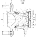
図1は、本発明に係る回転速度検出装置付き車輪用軸受装置の第1の実施形態を示す図2のI−O−I線に沿った縦断面図、図2は、図1の側面図、図3は、図1の検出部を示す要部拡大図、図4は、図2のドレーン部を示す要部拡大図、図5は、図3の変形例を示す要部拡大図である。なお、以下の説明では、車両に組み付けた状態で車両の外側寄りとなる側をアウター側(図1の左側)、中央寄り側をインナー側(図1の右側)という。
Hereinafter, embodiments of the present invention will be described in detail with reference to the drawings.
FIG. 1 is a longitudinal sectional view taken along line I-O-I in FIG. 2 showing a first embodiment of a wheel bearing device with a rotational speed detection device according to the present invention, and FIG. 2 is a side view of FIG. 3 is an enlarged view of the main part showing the detection unit of FIG. 1, FIG. 4 is an enlarged view of the main part showing the drain part of FIG. 2, and FIG. 5 is an enlarged view of the main part showing a modification of FIG. . In the following description, the side closer to the outer side of the vehicle when assembled to the vehicle is referred to as the outer side (left side in FIG. 1), and the side closer to the center is referred to as the inner side (right side in FIG. 1).
この回転速度検出装置付き車輪用軸受装置は従動輪側の第3世代と呼称され、内方部材1と外方部材2、および両部材1、2間に転動自在に収容された複列の転動体(ボール)3a、3b列とを備えている。内方部材1は、ハブ輪4と、このハブ輪4に所定のシメシロを介して圧入された内輪5とからなる。
This wheel bearing device with a rotational speed detection device is called the third generation on the driven wheel side, and is a double row of rollers accommodated between the
ハブ輪4は、アウター側の端部に車輪(図示せず)を取り付けるための車輪取付フランジ6を一体に有し、外周に一方(アウター側)の内側転走面4aと、この内側転走面4aから軸方向に延びる軸状部4dを介して小径段部4bが形成されている。車輪取付フランジ6にはハブボルト6aが周方向等配に植設されている。
The
また、ハブ輪4のアウター側端部には軸方向に延びるすり鉢状の凹所10が形成されている。この凹所10は鍛造加工によってアウター側の内側転走面4aの溝底部まで形成され、ハブ輪4のアウター側の肉厚が略均一に設定されている。
A mortar-shaped
内輪5は、外周に他方(インナー側)の内側転走面5aが形成され、ハブ輪4の小径段部4bに圧入されて背面合せタイプの複列アンギュラ玉軸受を構成すると共に、小径段部4bの端部を塑性変形させて形成した加締部4cによって内輪5が軸方向に固定されている。これにより、軽量・コンパクト化を図ることができる。なお、内輪5および転動体3a、3bはSUJ2等の高炭素クロム鋼で形成され、ズブ焼入れによって芯部まで58〜64HRCの範囲に硬化処理されている。
The
ハブ輪4はS53C等の炭素0.40〜0.80wt%を含む中高炭素鋼で形成され、内側転走面4aをはじめ、車輪取付フランジ6のインナー側の基部6bから小径段部4bに亙って高周波焼入れによって表面硬さを58〜64HRCの範囲に硬化処理されている。なお、加締部4cは鍛造加工後の表面硬さの生のままとされている。これにより、車輪取付フランジ6に負荷される回転曲げ荷重に対して充分な機械的強度を有し、内輪5の嵌合部となる小径段部4bの耐フレッティング性が向上すると共に、微小なクラック等の発生がなく加締部4cの塑性加工をスムーズに行うことができる。
The
外方部材2は、外周にナックル(図示せず)に取り付けられるための車体取付フランジ2cを一体に有し、内周にハブ輪4の内側転走面4aに対向するアウター側の外側転走面2aと、内輪5の内側転走面5aに対向するインナー側の外側転走面2bが一体に形成されている。これら両転走面間に複列の転動体3a、3b列が収容され、保持器7、8によって転動自在に保持されている。そして、外方部材2と内方部材1との間に形成される環状空間のアウター側の開口部にシール9が装着されると共に、インナー側の開口部には後述するキャップ14が装着され、軸受内部に封入されたグリースの外部への漏洩と、外部から雨水やダスト等が軸受内部に侵入するのを防止している。
The
外方部材2はS53C等の炭素0.40〜0.80wt%を含む中高炭素鋼で形成され、複列の外側転走面2a、2bが高周波焼入れによって表面硬さを58〜64HRCの範囲に硬化処理されている。なお、ここでは、転動体3a、3bにボールを使用した複列アンギュラ玉軸受を例示したが、これに限らず、円錐ころを使用した複列円錐ころ軸受であっても良い。また、従動輪側の第3世代構造に限らず、第2世代、あるいは第4世代構造であっても良い。
The
本実施形態では、アウター側の転動体3a列のピッチ円直径PCDoがインナー側の転動体3b列のピッチ円直径PCDiよりも大径に設定されると共に、アウター側の転動体3a列の転動体径doがインナー側の転動体3b列の転動体径diよりも小径(do<di)に設定されている。このピッチ円直径PCDo、PCDiと転動体径do、diの違いにより、アウター側の転動体3a列の転動体数Zoがインナー側の転動体3b列の転動体数Ziよりも多く設定されている(Zo>Zi)。これにより、インナー側に比べアウター側部分の軸受剛性を増大させることができ、軸受の長寿命化を図ることができる。なお、ここでは、アウター側の転動体3aとインナー側の転動体3bがサイズの異なるものを例示したが、これに限らず、両列同じサイズであっても良い。
In the present embodiment, the pitch circle diameter PCDo of the outer rolling
本実施形態では、内輪5の外周にパルサリング11が圧入されている。このパルサリング11は、図3に拡大して示すように、円環状に形成された支持環12と、この支持環12の側面に加硫接着等で一体に接合された磁気エンコーダ13とで構成されている。この磁気エンコーダ13は、ゴム等のエラストマにフェライト等の磁性体粉が混入され、周方向に交互に磁極N、Sが着磁されて車輪の回転速度検出用のロータリエンコーダを構成している。
In the present embodiment, the
支持環12は強磁性体の鋼鈑、例えば、フェライト系のステンレス鋼鈑(JIS規格のSUS430系等)や防錆処理された冷間圧延鋼鈑(JIS規格のSPCC系等)からプレス加工によって断面略L字状に形成され、内輪5に圧入される円筒部12aと、この円筒部12aから径方向内方に延びる立板部12bとを有している。そして、この立板部12bのインナー側の側面に磁気エンコーダ13が接合されている。
The
ここで、図1に示すように、外方部材2にキャップ14が装着され、外方部材2のインナー側の開口部を閉塞している。このキャップ14は、耐食性を有し、後述する回転速度センサ18の感知性能に悪影響を及ぼさないように、非磁性体のオーステナイト系ステンレス鋼鈑(JIS規格のSUS304系等)をプレス成形してカップ状に形成され、外方部材2のインナー側の端部内周に圧入される外周面に合成ゴムからなる弾性部材が設けられた円筒状の嵌合部14aと、この嵌合部14aから縮径部14bを介して磁気エンコーダ13に僅かな軸方向すきまを介して対峙する円板部14cと、この円板部14cから屈曲部14dを介して内方部材1のインナー側の端部を覆う底部14eとを備えている。
Here, as shown in FIG. 1, a
ここで、図3に示すように、キャップ14の縮径部14bにNBR(アクリロニトリル−ブタジエンゴム)等の合成ゴムからなる弾性部材15が加硫接着によって一体に接合されている。この弾性部材15は、キャップ14の円板部14cの側面からインナー側に突出して回転速度センサ18に干渉しないように接合され、嵌合部14aの外径より径方向外方に突出する環状突起15aを備えている。そして、外方部材2の端部内周の嵌合面がビビリ高さ3μm以下に規制されると共に、この環状突起15aがキャップ14の嵌合時に外方部材2の端部内周に弾性変形して圧着され、嵌合部14aの気密性を高めている。
Here, as shown in FIG. 3, an
本実施形態では、キャップ14のインナー側に、さらにセンサキャップ16が装着されている。このセンサキャップ16は耐食性を有するオーステナイト系ステンレス鋼鈑(JIS規格のSUS304系)や、カチオン電着塗装あるいは亜鉛メッキ等、防錆処理された冷間圧延鋼鈑(JIS規格のSPCC系)等をプレス成形してカップ状に形成され、外方部材2のインナー側の端部外周に圧入される円筒状の嵌合部16aと、外方部材2のインナー側の端面に密着する底部16bとを備えている。このセンサキャップ16の底部16bには磁気エンコーダ13に対応する水平位置に嵌挿孔17が形成され、この嵌挿孔17に後述する回転速度センサ18が嵌挿される(図2参照)。このように、嵌挿孔17が水平位置に形成され、この嵌挿孔17に回転速度センサ18が装着されていれば、車輪からの横方向荷重により外方部材2と内方部材1が相対的に傾いた状態においても、回転速度センサ18と磁気エンコーダ13のエアギャップ変動を抑制することができ、安定した検出精度を得ることが出来る。
In the present embodiment, a
回転速度センサ18は、ホール素子、磁気抵抗素子(MR素子)等、磁束の流れ方向に応じて特性を変化させる磁気検出素子およびこの磁気検出素子の出力波形を整える波形整形回路が組み込まれたIC等からなり、車輪の回転速度を検出してその回転数を制御する自動車のアンチロックブレーキシステムを構成している。そして、この回転速度センサ18がキャップ14の円板部14cに衝合または近接するまで挿入されている。これにより、所望のエアギャップが得られ、煩雑なエアギャップ調整を省いて組立作業性の向上が図れると共に、嵌合部に合成ゴムからなる弾性部材15が設けられたキャップ14により軸受内部を密封することができ、密封性の向上を図った回転速度検出装置付き車輪用軸受装置を提供することができる。
The
センサキャップ16の中心部に形成された穿孔19に、底部16bの軸受内方側(アウター側)に固定ナット20が圧入されている(図1、図2参照)。そして、センサキャップ16の嵌挿孔17に嵌挿された回転速度センサ18が、図示しない取付部材を介して取付ボルトを固定ナット20に締結することによって固定されている。このように、取付ボルトの締結により固定ナット20が底部16bの内側面に引き込まれるため、固定ナット20の圧入だけで脱落を防止することができる。また、固定ナットの圧入部に軸方向溝等の回り止め形状が施されていれば、取付けボルト締結時のナットスリップに対しても有利である。
A fixing
また、本実施形態では、センサキャップ16の底部16bの径方向外方側にドレーン21が形成されている(図2、図4参照)。このドレーン21は、図2に示すように、嵌合部16aと底部16bの路面に近い側の隅部に形成されている。これにより、例えセンサキャップ16内に外部から雨水等の異物が浸入したとしてもこの異物がセンサキャップ16内を流動落下し、底部16bの径方向下部から異物を効果的に排出させることができる。なお、このドレーン21として矩形状の孔を例示したが、これに限らず、例えば、円孔であっても良いし、まゆ形であっても良い。
In the present embodiment, the
図5に、図3の変形例を示す。この実施形態は、前述したものと基本的にはキャップの構成が一部異なるだけで、その他同一部品同一部位あるいは同様の機能を有する部品や部位には同じ符合を付して詳細な説明を省略する。 FIG. 5 shows a modification of FIG. In this embodiment, basically, the cap configuration is only partially different from the one described above, and the same parts are denoted by the same reference numerals and the detailed description is omitted for the same parts or parts having the same function. To do.
外方部材2にキャップ22が装着され、外方部材2のインナー側の開口部を閉塞している。このキャップ22は、耐食性を有し、回転速度センサ18の感知性能に悪影響を及ぼさないように、非磁性体のオーステナイト系ステンレス鋼鈑(JIS規格のSUS304系等)をプレス成形してカップ状に形成され、外方部材2のインナー側の端部内周に圧入される合成ゴムからなる弾性部材15が設けられた円筒状の嵌合部22aと、この嵌合部22aから縮径部22bを介して磁気エンコーダ13に僅かな軸方向すきまを介して対峙する円板部22cとを備え、嵌合部22aから円板部22cに亙って、他の部分の肉厚H1よりも肉厚H2が薄く形成されている。具体的には、他の部分の肉厚H1が1.0〜1.5mmに対して、少なくとも円板部22cの肉厚H2が0.2〜1.0mmに形成されている。これにより、エアギャップを小さく設定することが可能になり、検出精度を高めることができる。なお、この肉厚H2が0.2mm未満では、円板部22cの形状を精度良く成形するのが難しくなると共に、1.0mmを超えると、エアギャップが大きくなって所望の磁気特性を得ることができず検出精度が低下する。
A
図6は、本発明に係る回転速度検出装置付き車輪用軸受装置の第2の実施形態を示す縦断面図、図7は、図6の検出部を示す要部拡大図、図8は、図6のドレーン部を示す要部拡大図である。なお、この実施形態は、前述した第1の実施形態(図1)と基本的にはセンサキャップの構成が異なるだけで、その他同一部品、同一部位あるいは同様の機能を有する部品や部位には同じ符合を付して詳細な説明を省略する。 FIG. 6 is a longitudinal sectional view showing a second embodiment of the wheel bearing device with a rotational speed detection device according to the present invention, FIG. 7 is an enlarged view of a main part showing the detection unit of FIG. 6, and FIG. FIG. 6 is an enlarged view of a main part showing a drain part of FIG. 6. This embodiment is basically the same as the first embodiment (FIG. 1) described above except that the configuration of the sensor cap is different, and is the same for other parts and parts having the same function, the same part, or similar functions. Detailed description will be omitted with reference numerals.
センサキャップ24は外方部材2の端部内周に圧入され、外方部材2のインナー側の開口部を閉塞している。このセンサキャップ24は、耐食性を有するオーステナイト系ステンレス鋼鈑(JIS規格のSUS304系)や、カチオン電着塗装あるいは亜鉛メッキ等、防錆処理された冷間圧延鋼鈑(JIS規格のSPCC系)等をプレス成形してカップ状に形成され、外方部材2のインナー側の端部内周に圧入される円筒状の嵌合部24aと、外方部材2のインナー側の端面に密着する底部24bとを備えている。このセンサキャップ24の底部24bの中心部またはその近傍に固定ナット20が圧入されている。本実施形態では、センサキャップ24が外方部材2の端部内周に圧入されているため、外嵌タイプよりもセンサキャップ24自体の剛性が高まり、走行中に飛石等が衝突しても変形や損傷するのを防止することができる。
The
ここで、図7に拡大して示すように、センサキャップ24の底部24bの磁気エンコーダ13に対応する位置に嵌挿孔17が形成され、この嵌挿孔17に回転速度センサ18が嵌挿されている。また、図8に拡大して示すように、センサキャップ24の底部24bの径方向外方側にドレーン25が形成されている。このドレーン25は、嵌合部24aと底部24bの路面に近い側の隅部に形成されている。これにより、センサキャップ24内に外部から雨水等の異物が浸入したとしてもこの異物がセンサキャップ24内を流動落下し、効果的に排出させることができる。
Here, as shown in an enlarged view in FIG. 7, an
図9は、本発明に係る回転速度検出装置付き車輪用軸受装置の第3の実施形態を示す縦断面図、図10は、図9のドレーン部を示す要部拡大図である。なお、この実施形態は、前述した第1の実施形態(図1)と基本的にはセンサキャップの構成が異なるだけで、その他同一部品、同一部位あるいは同様の機能を有する部品や部位には同じ符合を付して詳細な説明を省略する。 FIG. 9 is a longitudinal sectional view showing a third embodiment of the wheel bearing device with a rotational speed detection device according to the present invention, and FIG. 10 is an enlarged view of a main part showing the drain portion of FIG. This embodiment is basically the same as the first embodiment (FIG. 1) described above except that the configuration of the sensor cap is different, and is the same for other parts and parts having the same function, the same part, or similar functions. Detailed description will be omitted with reference numerals.
センサキャップ26は外方部材2の端部外周に圧入され、外方部材2のインナー側の開口部を閉塞している。このセンサキャップ26は、耐食性を有するオーステナイト系ステンレス鋼鈑(JIS規格のSUS304系)や、カチオン電着塗装あるいは亜鉛メッキ等、防錆処理された冷間圧延鋼鈑(JIS規格のSPCC系)等をプレス成形してカップ状に形成され、外方部材2のインナー側の端部外周に圧入される円筒状の嵌合部26aと、外方部材2のインナー側の端面に密着する底部26bとを備えている。そして、このセンサキャップ26の底部26bの中心部またはその近傍に固定ナット20が圧入されている。
The
ここで、図8に拡大して示すように、センサキャップ26の底部24bの径方向外方側にドレーン21が形成されている。また、本実施形態では、外方部材23の端部外周に環状溝27が形成され、センサキャップ26が外方部材2の端部内周に圧入されると共に、嵌合部26aの端部が環状溝27に塑性変形により加締部28が形成され、この加締部28によって車輪からの入力荷重により嵌合部が変形を繰り返すことによるセンサキャップ26が軸方向に移動するのを防止することができ、長期間に亘って当初のエアギャップを維持することができる。また、車輪入力荷重による外方部材23の嵌合部変形量は、外方部材23の肉厚が薄い方が大きく軸方向抜けには不利であるが、センサキャップ26の端面を加締ることにより軸方向抜けを防止できるため、一層の軸受軽量化が可能となる。
Here, as shown in an enlarged view in FIG. 8, the
以上、本発明の実施の形態について説明を行ったが、本発明はこうした実施の形態に何等限定されるものではなく、あくまで例示であって、本発明の要旨を逸脱しない範囲内において、さらに種々なる形態で実施し得ることは勿論のことであり、本発明の範囲は、特許請求の範囲の記載によって示され、さらに特許請求の範囲に記載の均等の意味、および範囲内のすべての変更を含む。 The embodiment of the present invention has been described above, but the present invention is not limited to such an embodiment, and is merely an example, and various modifications can be made without departing from the scope of the present invention. Of course, the scope of the present invention is indicated by the description of the scope of claims, and further, the equivalent meanings described in the scope of claims and all modifications within the scope of the scope of the present invention are included. Including.
本発明に係る回転速度検出装置付き車輪用軸受装置は、駆動輪用、従動輪用、あるいは転動体がボール、円錐ころ等、あらゆる構造の内輪回転タイプの車輪用軸受装置に適用することができる。 The wheel bearing device with a rotation speed detection device according to the present invention can be applied to a wheel bearing device of an inner ring rotation type having any structure such as a drive wheel, a driven wheel, or a rolling element such as a ball or a tapered roller. .
1 内方部材
2、23 外方部材
2a、2b 外側転走面
2c 車体取付フランジ
3 転動体
4 ハブ輪
4a、5a 内側転走面
4b 小径段部
4c 加締部
4d 軸状部
5 内輪
6 車輪取付フランジ
6a ハブボルト
6b 車輪取付フランジのインナー側の基部
7、8 保持器
9 シール
10 凹所
11 パルサリング
12 支持環
12a 円筒部
12b 立板部
13 磁気エンコーダ
14、22 キャップ
14a、16a、22a、24a、26a 嵌合部
14b、22b 縮径部
14c、22c 円板部
14d 屈曲部
14e、16b、24b、26b 底部
15 弾性部材
15a 環状突起
16、24、26 センサキャップ
17 挿入孔
18 回転速度センサ
19 穿孔
20 固定ナット
21、25 ドレーン
27 環状溝
28 加締部
51 外方部材
51a 外側転走面
51b 車体取付フランジ
52 内方部材
53 ボール
54 車輪取付フランジ
55 ハブ輪
55a、56a 内側転走面
55b 小径段部
56 内輪
57 保持器
58 加締部
59 シール
60 磁気エンコーダ
61 支持環
62 エンコーダ本体
63 カバー
63a 筒部
63b、67b 蓋部
64 フランジ
65 センサ取付部
66 センサ取付穴
67 芯金
67a 筒状部
68 ケーブル
69 センサ
69a 挿入部
di インナー側の転動体列の転動体径
do アウター側の転動体列の転動体径
H1 キャップの肉厚
H2 キャップの円板部の肉厚
PCDi インナー側の転動体列のピッチ円直径
PCDo アウター側の転動体列のピッチ円直径
Zi インナー側の転動体列の転動体数
Zo アウター側の転動体列の転動体数
DESCRIPTION OF SYMBOLS 1 Inner member 2, 23 Outer member 2a, 2b Outer rolling surface 2c Car body mounting flange 3 Rolling body 4 Hub wheel 4a, 5a Inner rolling surface 4b Small diameter step part 4c Clamping part 4d Shaft part 5 Inner ring 6 Wheel Mounting flange 6a Hub bolt 6b Inner side base 7, 8 of wheel mounting flange Cage 9 Seal 10 Recess 11 Pulsar ring 12 Support ring 12a Cylindrical portion 12b Standing plate portion 13 Magnetic encoder 14, 22 Caps 14a, 16a, 22a, 24a, 26a Fitting portion 14b, 22b Reduced diameter portion 14c, 22c Disc portion 14d Bending portion 14e, 16b, 24b, 26b Bottom portion 15 Elastic member 15a Annular projections 16, 24, 26 Sensor cap 17 Insertion hole 18 Rotational speed sensor 19 Perforation 20 Fixing nuts 21 and 25 Drain 27 Annular groove 28 Caulking portion 51 Outer member 51a Outer rolling surface 51b Flange 52 Inner member 53 Ball 54 Wheel mounting flange 55 Hub wheel 55a, 56a Inner rolling surface 55b Small diameter step portion 56 Inner ring 57 Cage 58 Clamping portion 59 Seal 60 Magnetic encoder 61 Support ring 62 Encoder body 63 Cover 63a Tube portion 63b, 67b Lid 64 Flange 65 Sensor mounting portion 66 Sensor mounting hole 67 Core metal 67a Tubular portion 68 Cable 69 Sensor 69a Insertion di Rolling element diameter of inner side rolling element row do Rolling body of outer side rolling element row Diameter H1 Cap thickness H2 Cap disc thickness PCDi Pitch circle diameter PCDo of inner side rolling element row Pitch Pitch circle diameter Zi of outer side rolling element row Zo Number of rolling elements of inner side rolling element row Zo Outer Number of rolling elements in the side rolling element row
Claims (12)
一端部に車輪を取り付けるための車輪取付フランジを一体に有し、外周に軸方向に延びる小径段部が形成されたハブ輪、およびこのハブ輪の小径段部に圧入された少なくとも一つの内輪とからなり、外周に前記複列の外側転走面に対向する複列の内側転走面が形成された内方部材と、
前記外方部材と内方部材のそれぞれの転走面間に転動自在に収容された複列の転動体と、
前記内輪に外嵌され、円周方向に特性を交互に、かつ等間隔に変化させたパルサリングと、
前記外方部材のインナー側の端部に嵌着され、鋼鈑からプレス加工により形成されたカップ状のセンサキャップ、およびこのセンサキャップに装着された回転速度センサとを備え、
当該回転速度センサが前記パルサリングに所定の軸方向エアギャップを介して対峙されている回転速度検出装置付き車輪用軸受装置において、
前記外方部材にカップ状のキャップが装着され、このキャップが非磁性の鋼鈑からプレス加工により形成され、前記外方部材のインナー側の端部内周に圧入される外周面に合成ゴムからなる弾性部材が設けられた円筒状の嵌合部と、この嵌合部から径方向内方に延び、前記パルサリングに僅かな軸方向すきまを介して対峙する円板部とを備えると共に、この円板部に前記回転速度センサが衝合または近接され、当該キャップを介して前記パルサリングに対向配置されていることを特徴とする回転速度検出装置付き車輪用軸受装置。 An outer member in which a double row outer rolling surface is integrally formed on the inner periphery;
A hub wheel integrally having a wheel mounting flange for mounting a wheel at one end, and having a small-diameter step portion extending in the axial direction on the outer periphery, and at least one inner ring press-fitted into the small-diameter step portion of the hub ring; An inner member in which a double row inner rolling surface facing the outer rolling surface of the double row is formed on the outer periphery,
A double row rolling element accommodated in a freely rolling manner between the rolling surfaces of the outer member and the inner member;
Pulsar ring that is externally fitted to the inner ring, and the characteristics are changed alternately and at equal intervals in the circumferential direction;
Is fitted to the inner side end of the outer member comprises a steel plate cup-shaped sensor cap formed by press working, and a rotational speed sensor attached to the sensor cap,
In the wheel bearing device with a rotational speed detection device, wherein the rotational speed sensor is opposed to the pulsar ring via a predetermined axial air gap,
A cup-shaped cap is attached to the outer member, and the cap is formed by pressing from a non-magnetic steel plate and is made of synthetic rubber on the outer peripheral surface that is press-fitted into the inner periphery of the inner side end of the outer member. The disc includes a cylindrical fitting portion provided with an elastic member, and a disc portion extending radially inward from the fitting portion and facing the pulsar ring via a slight axial clearance. A wheel bearing device with a rotational speed detecting device, wherein the rotational speed sensor is abutted or brought close to a portion and is arranged to face the pulsar ring via the cap.
Priority Applications (5)
| Application Number | Priority Date | Filing Date | Title |
|---|---|---|---|
| JP2009277963A JP5334823B2 (en) | 2009-12-07 | 2009-12-07 | Wheel bearing device with rotation speed detector |
| PCT/JP2010/066049 WO2011034134A1 (en) | 2009-09-17 | 2010-09-16 | Bearing device for a wheel, equipped with a rotational-speed measurement device |
| CN201080041438.4A CN102575715B (en) | 2009-09-17 | 2010-09-16 | Bearing device for a wheel, equipped with a rotational-speed measurement device |
| DE112010003668T DE112010003668T5 (en) | 2009-09-17 | 2010-09-16 | Wheel bearing device with incorporated speed detection device |
| US13/421,936 US8393795B2 (en) | 2009-09-17 | 2012-03-16 | Wheel bearing apparatus incorporated with a rotational speed detecting apparatus |
Applications Claiming Priority (1)
| Application Number | Priority Date | Filing Date | Title |
|---|---|---|---|
| JP2009277963A JP5334823B2 (en) | 2009-12-07 | 2009-12-07 | Wheel bearing device with rotation speed detector |
Publications (3)
| Publication Number | Publication Date |
|---|---|
| JP2011117583A JP2011117583A (en) | 2011-06-16 |
| JP2011117583A5 JP2011117583A5 (en) | 2013-01-24 |
| JP5334823B2 true JP5334823B2 (en) | 2013-11-06 |
Family
ID=44283135
Family Applications (1)
| Application Number | Title | Priority Date | Filing Date |
|---|---|---|---|
| JP2009277963A Active JP5334823B2 (en) | 2009-09-17 | 2009-12-07 | Wheel bearing device with rotation speed detector |
Country Status (1)
| Country | Link |
|---|---|
| JP (1) | JP5334823B2 (en) |
Cited By (1)
| Publication number | Priority date | Publication date | Assignee | Title |
|---|---|---|---|---|
| US10641336B2 (en) * | 2015-09-25 | 2020-05-05 | Ntn Corporation | Wheel bearing apparatus |
Families Citing this family (12)
| Publication number | Priority date | Publication date | Assignee | Title |
|---|---|---|---|---|
| CN103443486B (en) | 2011-03-09 | 2016-04-06 | Ntn株式会社 | Wheel bearing arrangement |
| JP5914077B2 (en) * | 2012-03-21 | 2016-05-11 | Ntn株式会社 | Wheel bearing device |
| JP5914086B2 (en) * | 2012-03-26 | 2016-05-11 | Ntn株式会社 | Wheel bearing device |
| JP5914213B2 (en) * | 2012-06-28 | 2016-05-11 | Ntn株式会社 | Wheel bearing device |
| JP5914082B2 (en) * | 2012-03-26 | 2016-05-11 | Ntn株式会社 | Wheel bearing device |
| JP5914090B2 (en) * | 2012-03-28 | 2016-05-11 | Ntn株式会社 | Wheel bearing device |
| EP2829755B1 (en) * | 2012-03-21 | 2018-10-31 | NTN Corporation | Wheel bearing apparatus |
| JP6290543B2 (en) * | 2013-04-03 | 2018-03-07 | Ntn株式会社 | Wheel bearing device |
| JP2014190464A (en) * | 2013-03-27 | 2014-10-06 | Ntn Corp | Bearing device for wheel |
| CN105121878B (en) | 2013-03-27 | 2018-07-31 | Ntn株式会社 | Wheel bearing arrangement |
| JP6114604B2 (en) * | 2013-03-27 | 2017-04-12 | Ntn株式会社 | Wheel bearing device with rotation speed detector |
| JP6012803B2 (en) * | 2015-03-31 | 2016-10-25 | Ntn株式会社 | Wheel bearing device |
Family Cites Families (4)
| Publication number | Priority date | Publication date | Assignee | Title |
|---|---|---|---|---|
| JPS62108002U (en) * | 1985-12-27 | 1987-07-10 | ||
| JP4114438B2 (en) * | 2002-08-27 | 2008-07-09 | 株式会社ジェイテクト | Rolling bearing device |
| JP5184875B2 (en) * | 2007-12-19 | 2013-04-17 | Ntn株式会社 | Wheel bearing device |
| JP5327077B2 (en) * | 2009-01-26 | 2013-10-30 | 日本精工株式会社 | Rolling bearing unit for wheel support with encoder |
-
2009
- 2009-12-07 JP JP2009277963A patent/JP5334823B2/en active Active
Cited By (1)
| Publication number | Priority date | Publication date | Assignee | Title |
|---|---|---|---|---|
| US10641336B2 (en) * | 2015-09-25 | 2020-05-05 | Ntn Corporation | Wheel bearing apparatus |
Also Published As
| Publication number | Publication date |
|---|---|
| JP2011117583A (en) | 2011-06-16 |
Similar Documents
| Publication | Publication Date | Title |
|---|---|---|
| JP5334823B2 (en) | Wheel bearing device with rotation speed detector | |
| JP5592130B2 (en) | Wheel bearing device with rotation speed detector | |
| JP5616758B2 (en) | Wheel bearing device with rotation speed detector | |
| US8393795B2 (en) | Wheel bearing apparatus incorporated with a rotational speed detecting apparatus | |
| JP5331640B2 (en) | Wheel bearing device with rotation speed detector | |
| WO2011027781A1 (en) | Wheel bearing unit with rotating speed detection device | |
| JP5334699B2 (en) | Wheel bearing device with rotation speed detector | |
| WO2006028209A1 (en) | Bearing device for wheel, having rotation speed detection device | |
| JP2013117455A (en) | Wheel bearing apparatus with rotation speed detection device | |
| JP4628049B2 (en) | Wheel bearing device with rotation speed detector | |
| JP5334820B2 (en) | Wheel bearing device with rotation speed detector | |
| JP2005300289A (en) | Wheel bearing device equipped with rotation speed detection device | |
| JP2011117476A (en) | Bearing device for wheel, equipped with rotational-speed detection device | |
| JP2016078512A (en) | Bearing device for wheel | |
| JP4964611B2 (en) | Wheel bearing device with rotation speed detector | |
| JP6239842B2 (en) | Wheel bearing device | |
| JP4628395B2 (en) | Wheel bearing device with rotation speed detector | |
| JP2009068597A (en) | Bearing device for wheel with encoder | |
| JP2009002385A (en) | Wheel bearing device with rotational speed detector | |
| JP4573194B2 (en) | Wheel bearing device with rotation speed detector | |
| JP4628053B2 (en) | Wheel bearing device with rotation speed detector | |
| JP2009030756A (en) | Bearing device for wheel with rotation speed detection device | |
| JP5213464B2 (en) | Wheel bearing device with rotation speed detector | |
| JP5914086B2 (en) | Wheel bearing device | |
| JP2006349061A (en) | Bearing device with rotational speed detector for wheel |
Legal Events
| Date | Code | Title | Description |
|---|---|---|---|
| A521 | Request for written amendment filed |
Free format text: JAPANESE INTERMEDIATE CODE: A523 Effective date: 20121128 |
|
| A621 | Written request for application examination |
Free format text: JAPANESE INTERMEDIATE CODE: A621 Effective date: 20121128 |
|
| TRDD | Decision of grant or rejection written | ||
| A01 | Written decision to grant a patent or to grant a registration (utility model) |
Free format text: JAPANESE INTERMEDIATE CODE: A01 Effective date: 20130708 |
|
| A61 | First payment of annual fees (during grant procedure) |
Free format text: JAPANESE INTERMEDIATE CODE: A61 Effective date: 20130730 |
|
| R150 | Certificate of patent or registration of utility model |
Ref document number: 5334823 Country of ref document: JP Free format text: JAPANESE INTERMEDIATE CODE: R150 Free format text: JAPANESE INTERMEDIATE CODE: R150 |
|
| R250 | Receipt of annual fees |
Free format text: JAPANESE INTERMEDIATE CODE: R250 |
|
| R250 | Receipt of annual fees |
Free format text: JAPANESE INTERMEDIATE CODE: R250 |
|
| R250 | Receipt of annual fees |
Free format text: JAPANESE INTERMEDIATE CODE: R250 |
|
| R250 | Receipt of annual fees |
Free format text: JAPANESE INTERMEDIATE CODE: R250 |
|
| R250 | Receipt of annual fees |
Free format text: JAPANESE INTERMEDIATE CODE: R250 |
|
| R250 | Receipt of annual fees |
Free format text: JAPANESE INTERMEDIATE CODE: R250 |
|
| R250 | Receipt of annual fees |
Free format text: JAPANESE INTERMEDIATE CODE: R250 |
|
| R250 | Receipt of annual fees |
Free format text: JAPANESE INTERMEDIATE CODE: R250 |
|
| R250 | Receipt of annual fees |
Free format text: JAPANESE INTERMEDIATE CODE: R250 |