JP2016536547A - Assembly product and method for assembling the assembly product - Google Patents
Assembly product and method for assembling the assembly product Download PDFInfo
- Publication number
- JP2016536547A JP2016536547A JP2016541936A JP2016541936A JP2016536547A JP 2016536547 A JP2016536547 A JP 2016536547A JP 2016541936 A JP2016541936 A JP 2016541936A JP 2016541936 A JP2016541936 A JP 2016541936A JP 2016536547 A JP2016536547 A JP 2016536547A
- Authority
- JP
- Japan
- Prior art keywords
- edge
- groove
- assembly product
- locking device
- locking devices
- Prior art date
- Legal status (The legal status is an assumption and is not a legal conclusion. Google has not performed a legal analysis and makes no representation as to the accuracy of the status listed.)
- Granted
Links
- 238000000034 method Methods 0.000 title description 9
- 238000003780 insertion Methods 0.000 claims abstract description 22
- 230000037431 insertion Effects 0.000 claims abstract description 22
- 210000002105 tongue Anatomy 0.000 description 44
- 239000000047 product Substances 0.000 description 43
- 238000000354 decomposition reaction Methods 0.000 description 6
- 238000010276 construction Methods 0.000 description 2
- 239000002245 particle Substances 0.000 description 2
- 229920002522 Wood fibre Polymers 0.000 description 1
- 238000005520 cutting process Methods 0.000 description 1
- 238000010586 diagram Methods 0.000 description 1
- 238000006073 displacement reaction Methods 0.000 description 1
- 238000005304 joining Methods 0.000 description 1
- 238000004519 manufacturing process Methods 0.000 description 1
- 238000003801 milling Methods 0.000 description 1
- 239000011265 semifinished product Substances 0.000 description 1
- 239000007787 solid Substances 0.000 description 1
- 239000002023 wood Substances 0.000 description 1
- 239000002025 wood fiber Substances 0.000 description 1
Images


Classifications
-
- F—MECHANICAL ENGINEERING; LIGHTING; HEATING; WEAPONS; BLASTING
- F16—ENGINEERING ELEMENTS AND UNITS; GENERAL MEASURES FOR PRODUCING AND MAINTAINING EFFECTIVE FUNCTIONING OF MACHINES OR INSTALLATIONS; THERMAL INSULATION IN GENERAL
- F16B—DEVICES FOR FASTENING OR SECURING CONSTRUCTIONAL ELEMENTS OR MACHINE PARTS TOGETHER, e.g. NAILS, BOLTS, CIRCLIPS, CLAMPS, CLIPS OR WEDGES; JOINTS OR JOINTING
- F16B12/00—Jointing of furniture or the like, e.g. hidden from exterior
- F16B12/10—Jointing of furniture or the like, e.g. hidden from exterior using pegs, bolts, tenons, clamps, clips, or the like
-
- A—HUMAN NECESSITIES
- A47—FURNITURE; DOMESTIC ARTICLES OR APPLIANCES; COFFEE MILLS; SPICE MILLS; SUCTION CLEANERS IN GENERAL
- A47B—TABLES; DESKS; OFFICE FURNITURE; CABINETS; DRAWERS; GENERAL DETAILS OF FURNITURE
- A47B47/00—Cabinets, racks or shelf units, characterised by features related to dismountability or building-up from elements
- A47B47/04—Cabinets, racks or shelf units, characterised by features related to dismountability or building-up from elements made mainly of wood or plastics
- A47B47/042—Panels connected without frames
-
- F—MECHANICAL ENGINEERING; LIGHTING; HEATING; WEAPONS; BLASTING
- F16—ENGINEERING ELEMENTS AND UNITS; GENERAL MEASURES FOR PRODUCING AND MAINTAINING EFFECTIVE FUNCTIONING OF MACHINES OR INSTALLATIONS; THERMAL INSULATION IN GENERAL
- F16B—DEVICES FOR FASTENING OR SECURING CONSTRUCTIONAL ELEMENTS OR MACHINE PARTS TOGETHER, e.g. NAILS, BOLTS, CIRCLIPS, CLAMPS, CLIPS OR WEDGES; JOINTS OR JOINTING
- F16B12/00—Jointing of furniture or the like, e.g. hidden from exterior
- F16B12/10—Jointing of furniture or the like, e.g. hidden from exterior using pegs, bolts, tenons, clamps, clips, or the like
- F16B12/12—Jointing of furniture or the like, e.g. hidden from exterior using pegs, bolts, tenons, clamps, clips, or the like for non-metal furniture parts, e.g. made of wood, of plastics
- F16B12/26—Jointing of furniture or the like, e.g. hidden from exterior using pegs, bolts, tenons, clamps, clips, or the like for non-metal furniture parts, e.g. made of wood, of plastics using snap-action elements
-
- F—MECHANICAL ENGINEERING; LIGHTING; HEATING; WEAPONS; BLASTING
- F16—ENGINEERING ELEMENTS AND UNITS; GENERAL MEASURES FOR PRODUCING AND MAINTAINING EFFECTIVE FUNCTIONING OF MACHINES OR INSTALLATIONS; THERMAL INSULATION IN GENERAL
- F16B—DEVICES FOR FASTENING OR SECURING CONSTRUCTIONAL ELEMENTS OR MACHINE PARTS TOGETHER, e.g. NAILS, BOLTS, CIRCLIPS, CLAMPS, CLIPS OR WEDGES; JOINTS OR JOINTING
- F16B12/00—Jointing of furniture or the like, e.g. hidden from exterior
- F16B12/44—Leg joints; Corner joints
- F16B12/46—Non-metal corner connections
-
- A—HUMAN NECESSITIES
- A47—FURNITURE; DOMESTIC ARTICLES OR APPLIANCES; COFFEE MILLS; SPICE MILLS; SUCTION CLEANERS IN GENERAL
- A47B—TABLES; DESKS; OFFICE FURNITURE; CABINETS; DRAWERS; GENERAL DETAILS OF FURNITURE
- A47B2230/00—Furniture jointing; Furniture with such jointing
- A47B2230/0074—Mortise and tenon joints or the like including some general male and female connections
- A47B2230/0081—Mortise and tenon type joints with some general male and female joints
-
- A—HUMAN NECESSITIES
- A47—FURNITURE; DOMESTIC ARTICLES OR APPLIANCES; COFFEE MILLS; SPICE MILLS; SUCTION CLEANERS IN GENERAL
- A47B—TABLES; DESKS; OFFICE FURNITURE; CABINETS; DRAWERS; GENERAL DETAILS OF FURNITURE
- A47B2230/00—Furniture jointing; Furniture with such jointing
- A47B2230/0074—Mortise and tenon joints or the like including some general male and female connections
- A47B2230/0096—Assembling sheet parts by male and female parts formed in the sheet thickness
-
- F—MECHANICAL ENGINEERING; LIGHTING; HEATING; WEAPONS; BLASTING
- F16—ENGINEERING ELEMENTS AND UNITS; GENERAL MEASURES FOR PRODUCING AND MAINTAINING EFFECTIVE FUNCTIONING OF MACHINES OR INSTALLATIONS; THERMAL INSULATION IN GENERAL
- F16B—DEVICES FOR FASTENING OR SECURING CONSTRUCTIONAL ELEMENTS OR MACHINE PARTS TOGETHER, e.g. NAILS, BOLTS, CIRCLIPS, CLAMPS, CLIPS OR WEDGES; JOINTS OR JOINTING
- F16B12/00—Jointing of furniture or the like, e.g. hidden from exterior
- F16B12/44—Leg joints; Corner joints
- F16B12/46—Non-metal corner connections
- F16B2012/466—Non-metal corner connections using mortise and tenon joints
-
- Y—GENERAL TAGGING OF NEW TECHNOLOGICAL DEVELOPMENTS; GENERAL TAGGING OF CROSS-SECTIONAL TECHNOLOGIES SPANNING OVER SEVERAL SECTIONS OF THE IPC; TECHNICAL SUBJECTS COVERED BY FORMER USPC CROSS-REFERENCE ART COLLECTIONS [XRACs] AND DIGESTS
- Y10—TECHNICAL SUBJECTS COVERED BY FORMER USPC
- Y10T—TECHNICAL SUBJECTS COVERED BY FORMER US CLASSIFICATION
- Y10T403/00—Joints and connections
- Y10T403/44—Three or more members connected at single locus
- Y10T403/443—All encompassed
-
- Y—GENERAL TAGGING OF NEW TECHNOLOGICAL DEVELOPMENTS; GENERAL TAGGING OF CROSS-SECTIONAL TECHNOLOGIES SPANNING OVER SEVERAL SECTIONS OF THE IPC; TECHNICAL SUBJECTS COVERED BY FORMER USPC CROSS-REFERENCE ART COLLECTIONS [XRACs] AND DIGESTS
- Y10—TECHNICAL SUBJECTS COVERED BY FORMER USPC
- Y10T—TECHNICAL SUBJECTS COVERED BY FORMER US CLASSIFICATION
- Y10T403/00—Joints and connections
- Y10T403/44—Three or more members connected at single locus
- Y10T403/447—Mutually contacting
Landscapes
- Engineering & Computer Science (AREA)
- General Engineering & Computer Science (AREA)
- Mechanical Engineering (AREA)
- Life Sciences & Earth Sciences (AREA)
- Wood Science & Technology (AREA)
- Assembled Shelves (AREA)
- Toys (AREA)
- Furniture Connections (AREA)
- Connection Of Plates (AREA)
- Basic Packing Technique (AREA)
- Packages (AREA)
Abstract
3つの異なる面に配設された少なくとも3つの要素を含む組立製品を提供する。第1要素(1)が第2要素(2)に対して直交して連結されるとともに、第3要素(4)が前記第2要素に対して直交して連結される。組み立て製品は1つ以上の係止装置を含み、それぞれの係止装置は、前記少なくとも3つの要素のうちの1つの要素の挿入溝(20)に配設される可撓性舌部(30)を備えている。前記可撓性舌部は、前記少なくとも3つの要素のうちの隣接する要素における舌部用溝(10)と、前記1つの要素と前記隣接する要素とを互いに係止するように協働する。前記第2要素(2)の第2縁部が、前記第3要素(4)の第2縁部に、前記係止装置のうちの1番目の係止装置によって連結されている。An assembly is provided that includes at least three elements disposed on three different surfaces. The first element (1) is connected orthogonally to the second element (2), and the third element (4) is connected orthogonally to the second element. The assembled product includes one or more locking devices, each locking device being a flexible tongue (30) disposed in an insertion groove (20) of one of the at least three elements. It has. The flexible tongue cooperates to lock the tongue groove (10) in an adjacent element of the at least three elements and the one element and the adjacent element. A second edge of the second element (2) is connected to a second edge of the third element (4) by a first locking device of the locking devices.
Description
本発明は、ボックスや引き出し等の組立製品、家具部品又は家具製品と、当該製品を組み立てる方法に関する。組立製品は、可撓性の舌部(実(さね))を備えた係止装置を設けられている。 The present invention relates to an assembly product such as a box or a drawer, a furniture part or a furniture product, and a method for assembling the product. The assembly product is provided with a locking device with a flexible tongue.
従来の家具製品は、例えばWO2012/154113A1号に示されるような機械的係止システムを設けられている。家具製品は、挿入溝内の可撓性舌部を備えた機械的係止システムにより第2パネルに対して直交して連結された第1パネルを備えている。 Conventional furniture products are provided with a mechanical locking system as shown, for example, in WO2012 / 154113A1. The furniture product comprises a first panel connected orthogonally to the second panel by a mechanical locking system with a flexible tongue in the insertion groove.
本発明のいくつかの実施形態の目的は、上述の技術及び周知技術に対する改良を提供することである。具体的な目的は、家具製品を組み立てる方法を改良することである。 The purpose of some embodiments of the invention is to provide improvements to the techniques described above and to known techniques. A specific objective is to improve the method of assembling furniture products.
本発明の更なる目的は、高い強度及び安定性を有する家具製品を提供することである。 A further object of the present invention is to provide a furniture product having high strength and stability.
本発明の開示から明瞭である上述の及び他の目的と利点のうちの少なくともいくつかは、3つの異なる面に配設された少なくとも3つの要素を備えた組立製品により達成されている。すなわち、第1要素が第2要素に対して実質的に直交して連結されるとともに、第3要素だ第2要素に対して実質的に直交連結される。組立製品は1つ以上の係止装置を備え、それぞれの係止装置は、少なくとも3つの要素のうちの1つの要素における挿入溝に配設される可撓性舌部を備えている。可撓性舌部は、少なくとも3つの要素のうちの隣接する要素の舌部用溝と、1つの要素と隣接する要素とを互いに係止するように協働する。第2要素の第2縁部が、第3要素の第2縁部に、係止装置のうちの1番目の係止装置によって連結される。 At least some of the above and other objects and advantages that are apparent from the present disclosure have been achieved by an assembly comprising at least three elements disposed on three different surfaces. That is, the first element is connected to the second element substantially orthogonally, and the third element is substantially orthogonally connected to the second element. The assembly includes one or more locking devices, each locking device including a flexible tongue that is disposed in an insertion groove in one of the at least three elements. The flexible tongue cooperates to lock the tongue groove of an adjacent element of at least three elements and the element adjacent to one element to each other. The second edge of the second element is connected to the second edge of the third element by the first locking device of the locking devices.
これらの要素は、プラスチック製のパネル、又は、HDFボード、パーティクルボード、中実木製ボード等の木質繊維系ボード等のパネルであり得る。パネルは、化粧層を設けられている。 These elements may be plastic panels or panels such as wood fiber boards such as HDF boards, particle boards, solid wood boards. The panel is provided with a decorative layer.
組立製品は、引き出し、食器棚、本棚、衣装箪笥、台所設備、物品を収納又は移送するためのボックス等の家具部品又は家具製品であり得る。 The assembly product can be a furniture part or furniture product such as a drawer, cupboard, book shelf, costume basket, kitchen equipment, box for storing or transporting articles.
好適には、3つのパネルは、互いに対して実質的に直交している(垂直である)(perpendicular)。 Preferably, the three panels are substantially orthogonal (perpendicular) to each other.
第3要素の第1縁部が、第1要素の第1縁部に、係止装置のうちの2番目の係止装置によって連結され得る。第1要素と第2要素は、それぞれ、フレームの第1ボードと第2ボードであり得るとともに、第3要素は本棚や衣装箪笥の背面部品であり得る。第1及び第2の係止装置によって連結される背面部品等の第3部品は、組立製品の強度を増加し得る。第1要素と第2要素との間の角度は、第3要素の第1縁部と第2縁部との間の角度によって案内され得る。直角に交わる角部を有する本棚や衣装箪笥が、本明細書に記載される実施形態によって容易に得られるであろう。組み立てや分解を簡単にするために、第3要素の第1縁部は第1要素の第1縁部に沿って摺動可能に連結される。 The first edge of the third element may be connected to the first edge of the first element by a second locking device of the locking devices. The first element and the second element can be the first board and the second board of the frame, respectively, and the third element can be the back part of the bookshelf or costume basket. A third part, such as a back part connected by the first and second locking devices, can increase the strength of the assembly. The angle between the first element and the second element can be guided by the angle between the first edge and the second edge of the third element. A bookshelf or garment with corners that intersect at right angles would be easily obtained by the embodiments described herein. To simplify assembly and disassembly, the first edge of the third element is slidably coupled along the first edge of the first element.
第6要素の第1縁部が、第2要素と第4要素との間において第1要素に対して実質的に直交して連結され得る。第6要素は、第2要素及び第4要素に実質的に平行である。第6要素の体1縁部は、係止装置のうちの7番目の係止装置によって連結され得る。好適には、係止装置のうちの7番目の係止装置の可撓性舌部が、第6要素の第1縁部における挿入溝に配設される。第6要素は、本棚等の組立製品の固定された棚であり得る。
The first edge of the sixth element may be connected substantially perpendicular to the first element between the second element and the fourth element. The sixth element is substantially parallel to the second element and the fourth element. The
第4要素が、第1要素に対して実質的に直交して連結され得る。ここで、第3要素の第3縁部が、第4要素の第2縁部に、係止装置のうちの3番目の係止装置によって連結され得る。 The fourth element can be coupled substantially orthogonal to the first element. Here, the third edge of the third element can be connected to the second edge of the fourth element by a third locking device of the locking devices.
第2要素と第4要素は、実質的に平行に配設され得るとともに、分解を簡単にするために第3要素は第2要素及び第4要素に対して摺動可能に連結され得る。 The second element and the fourth element can be arranged substantially in parallel, and the third element can be slidably connected to the second element and the fourth element for ease of disassembly.
第3要素の第4縁部が、第5要素の第2縁部における溝に配設され得る。第5要素は、第2要素及び第4要素に対して実質的に直交して連結され得る。 The fourth edge of the third element may be disposed in the groove at the second edge of the fifth element. The fifth element may be coupled substantially orthogonal to the second element and the fourth element.
組立製品は、前面パネルであり得る第5要素を有さない引き出し用半製品であり得る。第1、第2及び第4要素は、フレームのボードであり得るとともに、第3要素は底面ボードであり得る。前面パネルは、同じ工場にて半製品としての第2要素及び第4要素に対して実質的に直交して連結され得る。或いは、前面パネルは、別の工場にて、又は建設現場の作業員によって、第2要素及び第4要素に対して実質的に直交して連結され得る。 The assembly product may be a semi-drawing product that does not have a fifth element, which may be a front panel. The first, second and fourth elements can be frame boards and the third element can be a bottom board. The front panel may be connected substantially orthogonally to the second and fourth elements as semi-finished products at the same factory. Alternatively, the front panel may be connected substantially orthogonal to the second element and the fourth element at another factory or by construction site workers.
第5要素の第1縁部が、第2要素の第3縁部に、係止装置のうちの4番目の係止装置によって連結され得るとともに、第5要素の第3縁部が、第4要素の第3縁部に、係止装置のうちの5番目の係止装置によって連結され得る。 The first edge of the fifth element can be coupled to the third edge of the second element by a fourth locking device of the locking devices, and the third edge of the fifth element is the fourth. It can be connected to the third edge of the element by a fifth locking device of the locking devices.
第1要素の第1縁部が、第2要素の第1縁部に、係止装置のうちの6番目の係止装置によって連結され得る。 The first edge of the first element may be connected to the first edge of the second element by a sixth locking device of the locking devices.
第4要素の第1縁部が、係止装置のうちの7番目の係止装置によって第1要素の第3縁部に連結され得る。 The first edge of the fourth element may be connected to the third edge of the first element by a seventh locking device of the locking devices.
係止装置のうちの少なくとも1つの係止装置における挿入溝は、少なくとも3つの要素のうちの1つの要素の縁部の略全長に沿って延在していてもよい。 The insertion groove in at least one of the locking devices may extend along substantially the entire length of the edge of one of the at least three elements.
係止装置のうちの少なくとも1つの係止装置における舌部用溝は、少なくとも3つの要素のうちの隣接する要素の縁部の略全長に沿って延在していてもよい。 The tongue groove in at least one of the locking devices may extend along substantially the entire length of the edge of an adjacent element of the at least three elements.
1つの要素と隣接する要素の略全幅(すなわち縁部)に沿ってそれぞれ延在する挿入溝と舌部用溝は、これらの挿入溝と舌部用溝の製造を簡単なものとし得る。舌部用溝と挿入溝は、1つの要素と隣接する要素とを変位することにより固定フライスヘッドを通過させて製造され得る。 An insertion groove and tongue groove extending along substantially the entire width (ie, edge) of one element and an adjacent element, respectively, can simplify the manufacture of these insertion grooves and tongue grooves. The tongue groove and the insertion groove can be manufactured through a stationary milling head by displacing one element and an adjacent element.
係止装置のうちの少なくとも1つの係止装置における可撓性舌部は、係止装置の係止及び解除中に、挿入溝において変位可能である。 The flexible tongue on at least one of the locking devices is displaceable in the insertion groove during locking and unlocking of the locking device.
係止装置は、要素のうちの1つの要素において、又は要素のうちの隣接する要素において縁部分用溝を備え得る。1つの要素及び隣接する要素のうちの他方の要素の縁部分は、1つの要素と他の要素とを互いに係止するように当該縁部用溝と協働し得る。可撓性舌部と舌部用溝は、1つの要素と隣接する要素とを第1方向において係止するように協働するとともに、縁部分と縁部分用溝は1つの要素と隣接する要素とを第1方向に直交する第2方向において互いに係止するよに協働する。 The locking device may comprise an edge portion groove in one of the elements or in an adjacent element of the elements. An edge portion of one element and the other of the adjacent elements may cooperate with the edge groove to lock one element and the other element together. The flexible tongue and tongue groove cooperate to lock one element and an adjacent element in a first direction, and the edge portion and edge portion groove are elements adjacent to one element. Cooperate to lock each other in a second direction orthogonal to the first direction.
要素の縁部分は、校正溝を有し得る。 The edge portion of the element may have a calibration groove.
第3要素は、分解溝又は分解凹部を1つ以上の係止装置において有し得る。好適には、分解溝又は分解凹部は、分解ツールの挿入に適応している。分解ツールは、係止装置を解除するように分解溝又は分解凹部に挿入され得る。 The third element may have a disassembly groove or disassembly recess in one or more locking devices. Preferably, the disassembly groove or disassembly recess is adapted for insertion of a disassembly tool. The disassembly tool can be inserted into the disassembly groove or disassembly recess to release the locking device.
第1、第2、第4及び第5要素のいずれかに、分解溝が係止装置のいずれかにおいて設けられ得る。好適には、分解溝又は分解凹部は、分解ツールの挿入に適応している。分解ツールは、係止装置を解除するように分解溝又は分解凹部に挿入され得る。 Any of the first, second, fourth and fifth elements can be provided with a disassembly groove in any of the locking devices. Preferably, the disassembly groove or disassembly recess is adapted for insertion of a disassembly tool. The disassembly tool can be inserted into the disassembly groove or disassembly recess to release the locking device.
本発明の第2態様は、上述ように配設された少なくとも2つの要素を備えた家具製品等の組立製品である。第1要素の主面が第2要素の主面に対して直交する状態で、第1要素が係止装置によって隣接する第2要素に対して実質的に直交して連結される。係止装置は、第1要素及び第2要素のうちの一方の要素における挿入溝に配設される可撓性舌部を含んでいる。可撓性舌部は、第1要素及び第2要素のうちの他方の要素における舌部用溝と、第1要素と第2要素とを互いに係止するように協働する。第1要素又は隣接する第2要素は、係止装置を解除するための分解溝又は分解凹部を設けられている。好適には、分解溝又は分解凹部は、分解ツールの挿入に適応している。 The second aspect of the present invention is an assembly product such as a furniture product having at least two elements arranged as described above. In a state where the main surface of the first element is orthogonal to the main surface of the second element, the first element is connected to the adjacent second element by the locking device substantially orthogonally. The locking device includes a flexible tongue disposed in the insertion groove in one of the first element and the second element. The flexible tongue cooperates to lock the tongue groove in the other of the first element and the second element and the first element and the second element. The first element or the adjacent second element is provided with a disassembly groove or a disassembly recess for releasing the locking device. Preferably, the disassembly groove or disassembly recess is adapted for insertion of a disassembly tool.
係止装置は、第1要素又は隣接する第2要素における縁部分用溝を有し得る。第1要素及び隣接する第2要素のうちの他方の要素の縁部分は、第1要素と隣接する第2要素とを互いに係止するように、当該縁部分用溝と協働し得る。可撓性舌部と舌部用溝は、第1要素と隣接する第2要素とを第1方向において互いに係止するように協働するとともに、縁部分と縁部分用溝は、第1要素と隣接する第2要素とを第1方向に対して直交する第2方向において互いに係止するように協働する。好適には、分解溝又は分解凹部が縁部分に配設される。分解溝又は凹部は、カバープレートによって覆われ得る。 The locking device may have an edge portion groove in the first element or the adjacent second element. The edge portion of the other of the first element and the adjacent second element may cooperate with the edge portion groove so as to lock the first element and the adjacent second element with each other. The flexible tongue and the tongue groove cooperate to lock the first element and the adjacent second element in the first direction, and the edge portion and the edge portion groove are the first element. And the adjacent second element cooperate to lock each other in a second direction orthogonal to the first direction. Preferably, a disassembly groove or disassembly recess is disposed at the edge portion. The disassembly groove or recess can be covered by a cover plate.
一例として、本発明の実施形態を、添付の概略図面を参照しつつ更に詳細に説明する。 By way of example, embodiments of the present invention will be described in more detail with reference to the accompanying schematic drawings.
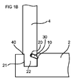
要素4を隣接する要素2の係止するための係止装置の実施形態が図1A及び1Bに示されている。要素4と隣接する要素2は、互いに対して直交して(垂直に)連結された家具製品のボードであり得る。すなわち、要素4の主面が隣接する要素2の主面に対して直交している。要素4と隣接する要素2とを互いに第1方向において係止するように、要素4の縁部分22が、隣接する要素2に縁部用溝21に配設されている。図1における実施例は、縁部用溝21における挿入溝20に配設された可撓性舌部30と、縁部分22における舌部用溝10と、を備えている。可撓性舌部30と舌部用溝10は、要素4と隣接する要素2とを互いに第1方向に対して実質的に直交する第2方向において係止するように協働する。要素4と隣接する要素2との組み立てにおいて、縁部分22が縁部用溝21に押し込まれると、可撓性舌部30が挿入溝20に押し込まれる。要素4と隣接する要素2とが連結状態に至ると、可撓性舌部30は跳ね返って舌部用溝内に入る。
An embodiment of a locking device for locking an
要素4は、本棚や衣装箪笥の背面部品であり得るとともに、隣接する要素2は本棚や衣装箪笥のフレームのボードであり得る。また、要素4は引き出しの底面であり得るとともに、隣接する要素2」は引き出しのフレームのボードであり得る。更に、要素4と隣接する要素2は、本棚、衣装ダンス又は引き出しのフレームの第1ボードと第2ボードでそれぞれあり得る。背面部品及び底面は、約2−4mmの厚さを有するHDFボード又はパーティクルボードであり得る。2mm未満の厚さを有する背面部品は、組立製品を安定させるには弱すぎるであろう。背面部品は、多くの家具製品について最大要素であって、4mmを超える厚さがあると背面部品の組み立てが厄介なものとなる。更なる実施形態は、上述の係止装置を1つ以上備え得る。図1A及び1Bに示す実施形態は、縁部分22の一側の校正溝40を含んでいる。しかしながら、縁部分22は、当該縁部の反対側の第2校正溝を含み得る(例えば、図6A参照)。
図2Aは、8個の係止装置を備えた本棚等の家具製品であって、フレームの一側が下方に面している。家具製品は、例えば本棚の一側面である第1要素1を備え、第1要素は、第1縁部において、係止装置のうちの1つによって、例えば本棚の上面である第2要素の第1縁部に連結される。例えば本棚の矩形背面部品である第3要素4の第1縁部が、第2要素の第2縁部に、係止装置のうちの別の係止装置によって連結される。第3要素4の第2縁部が、第1要素1の第2縁部に、別の係止装置によって連結される。例えば本棚の底面である第4要素5の第1縁部が、第1要素1の第3縁部に、係止装置のうちの別の係止装置によって連結される。第3要素4の第3縁部の縁部分22が、第4要素5の第2縁部における縁部分用溝21に配設され得る。例えば本棚の反対側面である第5要素6の第1縁部が、第4要素5の第3縁部に、係止装置のうちの別の係止装置によって連結されるとともに、第5要素6の第3縁部が、第2要素2の第3縁部に、係止装置のうちの別の係止装置によって連結される。第3要素4の第4縁部の縁部分22が、第5要素6の第2縁部における縁部分用溝21に配設され得る。第3要素4のそれぞれの第1縁部と第2縁部における係止装置は、それぞれ2つ以上の可撓性舌部30を備え得る。例えば本棚の棚である第6要素3であって、第1要素1及び第4要素5に対して平行に配設された第6要素が、第1縁部において第1要素1に、係止装置のうちの別の係止装置によって連結される。第6要素3の第3縁部が、第5要素6に、係止装置のうちの別の係止装置によって連結される。好適には、第6要素3の第1縁部と第3縁部のそれぞれにおける係止装置の可撓性舌部30が、縁部分22に配設される。
FIG. 2A is a furniture product such as a bookshelf provided with eight locking devices, and one side of the frame faces downward. The furniture product comprises, for example, a
図2Bは、第1要素1、第3要素4及び第5要素6の断面CS 2Bを示す。本図は、第3要素4の第4縁部の縁部分22が、第5要素6の第2縁部における縁部分用溝21に配設され得ることを示している。第3要素4は、機械的係止システムによって係止された2つ以上のボード4a‐4dを備え得る。第6要素3の第2縁部は、隣接するボードの縁部を連結するための係止装置のうちの別の係止装置(図示せず)を設けられ得る。図4Aは、ボード4a‐4dの機械的係止システムの実施形態を示している。機械的係止システムは、第1ボードの第1縁部における舌部60を備えている。舌部60は、第2ボードの第2縁部における舌部用溝50と、第1ボードと第2ボードとを第1方向において係止するように協働する。更に、係止システムは、第2縁部において係止要素71を有する突出ストリップ70を備えている。係止要素71は、第1縁部における係止溝80と、第1ボードと第2ボードとを第1方向に直交する第2方向において係止するように協働する。好適には、ボードと係止システムは係止ストリップ70が装着されるべき方向に面した状態で組立製品に配設される。このような状態で配設された場合、係止システムは係止した状態であり続け得る。
FIG. 2B shows a cross-section CS 2B of the
図2Cは、第2要素2と第3要素4の断面CS 2Cを示している。本実施形態において、第3要素4は分解溝33を有する。分解溝33は、可撓性舌部30を挿入溝20に押し込む分解ツール(図示せず)の挿入に適合するものであって、これにより第2要素と第3要素4との分解が簡単なものとなる。
FIG. 2C shows a
図3Aは、8個の係止装置を備えた本棚等の家具製品であって、フレームの一側が下方に面している。家具製品は、例えば本棚の一側面である第1要素1を備え、第1要素1は、第1縁部において、係止装置のうちの1つによって、例えば本棚の上面である第2要素の第1縁部に連結される。例えば本棚の矩形背面部品である第4要素の第1縁部が、第2要素の第2縁部に、係止装置のうちの別の係止装置によって連結される。第3要素4の第2縁部の縁部分22が、第1要素1の第2縁部の縁部分用溝21に挿入され得る。例えば本棚の底面である第4要素5の第1縁部が、第1要素1の第3縁部に、係止装置のうちの別の係止装置によって連結される。第3要素4の第3縁部が、第4要素5の第2縁部に、係止装置のうちの別の係止装置によって連結される。例えば本棚の側面である第5要素6の第1縁部が、第4要素5の第3縁部に、係止装置のうちの別の係止装置によって連結されるとともに、第5要素6の第3縁部が、第2要素の第3縁部に、係止装置のうちの別の係止装置によって連結される。第3要素4の第4縁部の縁部分22が、第5要素5の第2縁部における縁部部用溝21に配設され得る。第3要素4のそれぞれの第1縁部と第3縁部における係止装置は、それぞれ2つ以上の可撓性舌部30を備え得る。例えば本棚の棚である第6要素3であって、第1要素1及び第4要素5に対して平行に配設された第6要素が、第1縁部において第1要素1に、係止装置のうちの別の係止装置によって連結されるとともに、第6要素3の第3縁部が、第5要素6に、係止装置のうちの別の係止装置によって連結される。好適には、第6要素3の第1縁部と第3縁部それぞれにおける係止装置の可撓性舌部30が、縁部分22に配設される。好適には、分解を簡単にするように、第3要素4は、第1縁部と第2縁部において摺動可能に連結される。
FIG. 3A is a furniture product such as a bookshelf provided with eight locking devices, and one side of the frame faces downward. The furniture product comprises, for example, a
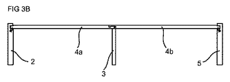
図3Bは、第1要素1、第3要素4及び第5要素6の断面CS 3Bを示している。第3要素4は、上述の機械的係止システムによって係止された2つ以上のボード4a及び4bを備え得る。
FIG. 3B shows a
図4Bは、図2A乃至2Cに記載の製品を組み立てる方法の実施形態を示している。好適には、第3要素4が製品に連結される前に、第1要素1、第2要素2及び第6要素3が互いに連結される。第3要素4は、第3要素4の第1縁部と第2縁部が、第1要素1の第2縁部と第2要素2の第2縁部に対して同時に連結されるように、斜め方向41に変位され得る。或いは、第3要素4を、第1要素1に対して直交する第1方向42において変位させ、その後第3要素4を第2要素2に対して直交する第2方向43において変位させる。本実施形態において、第3要素4の第1縁部は、第1縁部において変位可能に連結される。また或いは、第3要素4を第2要素2に対して直交する第2方向43において変位させ、その後第3要素4を第1要素1に対して直交する第1方向43において変位させる。本実施形態において、第3要素4の第2縁部が第2縁部において変位可能に連結される。更に、連結された第1要素1、第2要素2及び第6要素3を、一体的に方向41の斜め反対側に変位させてもよく、これにより第1要素1の第2縁部と第2要素の第2縁部とが第3要素4の第1縁部と第2縁部とに対して同時に連結される。
FIG. 4B illustrates an embodiment of a method for assembling the product described in FIGS. 2A-2C. Preferably, the
図5Aは、6個の係止装置を備えた引き出し等の家具製品であって、フレームの一側が下方に面している。家具製品は、例えば引き出しの内側面である第1要素1を備え、第1要素1は、第1縁部において、係止装置のうちの1つによって、例えば引き出しの一側面である第2要素2の第1縁部に連結されている。例えば引き出しの矩形底面である第3要素4の第1縁部が、第2要素2の第2縁部に、係止装置のうちの別の係止装置によって連結される。第3要素4の第2縁部の縁部分22が、第1要素1の第2縁部の縁部分用溝21に挿入され得る。例えば引き出しの側面である第4要素5の第1縁部が、第1要素1の第3縁部に、係止装置のうちの別の係止装置によって連結される。第3要素4の第3縁部が、第4要素5の第2縁部に、係止装置のうちの別の係止装置によって連結される。その後、例えば引き出しの前面パネルである第5要素6の第1縁部が、第4要素5の第3縁部に、別の係止装置によって連結されるとともに、第5要素6の第3縁部が、第2要素2の第3縁部に、係止装置のうちの別の係止装置によって連結される。第5要素6は、第1乃至第4要素1,2、4及び5が連結されるのと同じ工場で連結されてもよいし、又は別の工場において、或いは建設現場における作業員によって連結されてもよい。第3要素4の第4縁部の縁部分22が、第5要素5の第2縁部における縁部分用溝21に配設され得る。第3要素4のそれぞれの第1縁部及び第3縁部における係止装置は、それぞれ2つ以上の可撓性舌部30を備え得る。好適には、分解を簡単にするように、第3要素4は、第1縁部と第3縁部において摺動可能に連結される。
FIG. 5A is a furniture product such as a drawer provided with six locking devices, with one side of the frame facing downward. The furniture product comprises a
第5要素6(前面パネル)は、連結工程中に、第3要素4の第4縁部と、第2要素2の第3縁部と第4要素5の第3縁部とに対して直交する方向44において変位され得る。本実施形態における引き出しの底面パネルは、図4Bを参照して説明した方法と同じ方法で連結され得る。
The fifth element 6 (front panel) is orthogonal to the fourth edge of the
図5Bは、例えば第1要素1と第2要素2との間の角部分が、係止装置を見えないようにするためにカバープレート19を設けられ得ることを示している。
FIG. 5B shows that, for example, the corner between the
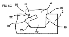
図6A−6Dは、係止装置の別の実施形態を示している。これらの実施形態において、校正溝40が縁部分22の一側又は両側に設けられ得る。舌部用溝10は、溝の上部及び下部において対称であり得る。これにより、係止装置の対向する位置において、すなわち鏡面反転した係止装置において同一の分解ツール(図示せず)が使用可能となる。縁部分用溝21は、縁部分22の縁部分用溝21への挿入をしやすくする案内面32を設けられ得る。図6C及び6Dに示すように、縁部分用溝21は2つの対向する舌部用溝10を設けられ得る。これら2つの対応する舌部用溝10は、現場の作業員等の最終切断者によって作製され得る。
6A-6D show another embodiment of a locking device. In these embodiments, a
図7Aは、2つの対向する舌部用溝10を有する実施形態が、2つの可撓性舌部30を設けられ得ることを示している。
FIG. 7A shows that an embodiment having two opposing
図7B−7Cは、対称的な分解ツール90を対称的な舌部用溝10に挿入することによる係止装置の分解工程を示している。
7B-7C show the disassembly process of the locking device by inserting a
図7D−7Eは、分解凹部を備えた別の実施形態を示している。これらの実施形態は、例えば引き出し、ボックス又は本棚等の家具製品の内部から係止装置を解除することが望ましい場合、図2Cに示す実施形態の代替実施形態であり得る。これらの実施形態は、図5Aに示す実施形態において、第5要素6を第2要素2及び第4要素5に連結するように利用され得る。舌部30が、図7Eにおいて縁部分用溝21に、図7Dにおいて縁部分22に配設されている。図7Eにおける縁部分22は、分解ツール90を収容するように構成された分解凹部34を設けられている。分解ツール90が分解凹部34に挿入されると、舌部30は、変位溝内20に押し返されて係止装置を解除する。分解凹部34は、カバープレート(図示せず)により覆われ得る。分解溝33又は分解凹部34を有する実施形態は、分解ツールを挿入するための舌部用溝10の外側端からアクセス可能な舌部用溝10を有さない実施形態に関して特に有利である。しかしながら、分解溝33又は分解凹部34を有する実施形態を、分解を簡単にするように任意の隣接する要素同士を連結するように利用することができる。
7D-7E show another embodiment with an exploded recess. These embodiments may be an alternative to the embodiment shown in FIG. 2C when it is desirable to release the locking device from inside a furniture product such as a drawer, box or bookshelf. These embodiments may be utilized to connect the
Claims (17)
第2要素(2)に対して直交して連結された第1要素(1)と、
前記第2要素に直交して連結された第3要素(4)と、を含み、
前記組立製品は、1つ以上の係止装置を備え、それぞれの係止装置は、前記少なくとも3つの要素のうちの1つの要素における挿入溝(20)に配設される可撓性舌部(30)を備え、
前記可撓性舌部は、前記少なくとも3つの要素のうちの隣接する要素における舌部用溝(10)と、前記1つの要素と前記隣接する要素とを互いに係止するように協働し、
前記第2要素(2)の第2縁部が、前記第3要素(4)の第2縁部に、前記係止装置のうちの1番目の係止装置によって連結されている、
ことを特徴とする組立製品。 An assembly comprising at least three elements arranged on three different surfaces,
A first element (1) connected orthogonally to the second element (2);
A third element (4) coupled orthogonally to the second element,
The assembly includes one or more locking devices, each locking device being a flexible tongue (20) disposed in an insertion groove (20) in one of the at least three elements. 30)
The flexible tongue cooperates to lock the tongue groove (10) in an adjacent element of the at least three elements and the one element and the adjacent element together;
A second edge of the second element (2) is connected to a second edge of the third element (4) by a first locking device of the locking devices;
An assembly product characterized by that.
請求項1に記載の組立製品。 A first edge of the third element (4) is connected to a first edge of the first element (1) by a second locking device of the locking devices;
The assembly product according to claim 1.
請求項1に記載の組立製品。 A fourth element is connected orthogonally to the first element (1), and a third edge of the third element (4) is connected to the second edge of the fourth element. Connected by a third locking device of the locking devices,
The assembly product according to claim 1.
請求項1乃至3のいずれか一項に記載の組立製品。 The fourth edge of the third element (4) is disposed in a groove in the second edge of the fifth element (6), and the fifth element (6) is the second element (2) and Connected orthogonally to the fourth element (5),
The assembly product according to any one of claims 1 to 3.
請求項4に記載の組立製品。 A first edge of the fifth element (6) is connected to a third edge of the second element by a fourth locking device of the locking devices and of the fifth element A third edge is connected to a third edge of the fourth element (5) by a fifth locking device of the locking devices;
The assembly product according to claim 4.
請求項1乃至5のいずれか一項に記載の組立製品。 A first edge of the first element (1) is connected to a first edge of the second element by a sixth locking device of the locking devices, and a fourth element (5 ) Is connected to the third edge of the first element by a seventh locking device of the locking devices,
The assembly product according to any one of claims 1 to 5.
請求項1乃至6のいずれか一項に記載の組立製品。 An insertion groove in at least one locking device of the locking devices extends along substantially the entire length of the edge of one of the at least three elements;
The assembly product according to any one of claims 1 to 6.
請求項1乃至7のいずれか一項に記載の組立製品。 The tongue groove in at least one of the locking devices extends along substantially the entire length of the edge of the adjacent element of the at least three elements,
The assembly product according to any one of claims 1 to 7.
請求項1乃至8のいずれか一項に記載の組立製品。 A flexible tongue in at least one of the locking devices is displaceable in the insertion groove,
The assembly product according to any one of claims 1 to 8.
前記1つの要素及び前記隣接する要素のうち他方の要素の縁部分が、前記1つの要素と前記隣接する要素とを互いに係止するように前記縁部分用溝と協働する、
請求項1乃至9のいずれか一項に記載の組立製品。 Each of the locking devices comprises an edge portion groove (22) in one of the elements and one of the adjacent elements.
An edge portion of the other element of the one element and the adjacent element cooperates with the edge portion groove so as to lock the one element and the adjacent element with each other.
The assembly product according to any one of claims 1 to 9.
請求項10に記載の組立製品。 The other edge portion of the one element and the adjacent element has a calibration groove (40),
The assembly product according to claim 10.
請求項1乃至11のいずれか一項に記載の組立製品。 The third element has a disassembly groove (33) or a disassembly recess (34), the disassembly groove being adapted for insertion of a disassembly tool,
The assembly product according to any one of claims 1 to 11.
請求項1乃至12のいずれか一項に記載の組立製品。 The assembly product is a furniture part;
The assembly product according to any one of claims 1 to 12.
請求項1乃至12のいずれか一項に記載の組立製品。 The assembly product is a furniture product;
The assembly product according to any one of claims 1 to 12.
請求項1乃至12のいずれか一項に記載の組立製品。 The assembly product is kitchen equipment;
The assembly product according to any one of claims 1 to 12.
請求項13に記載の組立製品。 The furniture part is a drawer;
The assembly product according to claim 13.
請求項14に記載の組立製品。 The furniture product is one of a cupboard, a bookcase, and a costume basket.
The assembly product according to claim 14.
Applications Claiming Priority (3)
| Application Number | Priority Date | Filing Date | Title |
|---|---|---|---|
| SE1351060 | 2013-09-16 | ||
| SE1351060-7 | 2013-09-16 | ||
| PCT/SE2014/051061 WO2015038059A1 (en) | 2013-09-16 | 2014-09-15 | An assembled product and a method of assembling the assembled product |
Publications (2)
| Publication Number | Publication Date |
|---|---|
| JP2016536547A true JP2016536547A (en) | 2016-11-24 |
| JP6396474B2 JP6396474B2 (en) | 2018-09-26 |
Family
ID=52666036
Family Applications (1)
| Application Number | Title | Priority Date | Filing Date |
|---|---|---|---|
| JP2016541936A Active JP6396474B2 (en) | 2013-09-16 | 2014-09-15 | Assembly product and method for assembling the assembly product |
Country Status (21)
| Country | Link |
|---|---|
| US (4) | US10451097B2 (en) |
| EP (3) | EP3047160B1 (en) |
| JP (1) | JP6396474B2 (en) |
| KR (1) | KR102250744B1 (en) |
| CN (2) | CN105518316B (en) |
| AU (1) | AU2014319008B2 (en) |
| BR (1) | BR112016005220B1 (en) |
| CA (1) | CA2922404C (en) |
| CL (1) | CL2016000500A1 (en) |
| DK (2) | DK3470690T3 (en) |
| EA (1) | EA032305B1 (en) |
| ES (2) | ES2717127T3 (en) |
| HR (2) | HRP20211821T1 (en) |
| LT (2) | LT3047160T (en) |
| MX (1) | MX369797B (en) |
| MY (1) | MY175374A (en) |
| PL (2) | PL3470690T3 (en) |
| SI (2) | SI3047160T1 (en) |
| TR (1) | TR201903765T4 (en) |
| UA (1) | UA120422C2 (en) |
| WO (1) | WO2015038059A1 (en) |
Families Citing this family (53)
| Publication number | Priority date | Publication date | Assignee | Title |
|---|---|---|---|---|
| UA109938C2 (en) | 2011-05-06 | 2015-10-26 | MECHANICAL LOCKING SYSTEM FOR CONSTRUCTION PANELS | |
| US9726210B2 (en) | 2013-09-16 | 2017-08-08 | Valinge Innovation Ab | Assembled product and a method of assembling the product |
| EA032305B1 (en) * | 2013-09-16 | 2019-05-31 | Велинге Инновейшн Аб | Assembled product |
| AU2014376416B2 (en) | 2014-01-10 | 2019-08-29 | Valinge Innovation Ab | A furniture panel |
| US9714672B2 (en) | 2014-01-10 | 2017-07-25 | Valinge Innovation Ab | Panels comprising a mechanical locking device and an assembled product comprising the panels |
| BR112016025783B1 (en) | 2014-05-09 | 2022-02-01 | Välinge Innovation AB | SET OF PANELS |
| RU2697150C2 (en) | 2014-07-11 | 2019-08-12 | Велинге Инновейшн Аб | Panel with slider |
| EP3234380B1 (en) | 2014-12-19 | 2019-09-11 | Välinge Innovation AB | Panels comprising a mechanical locking device |
| US10670064B2 (en) | 2015-04-21 | 2020-06-02 | Valinge Innovation Ab | Panel with a slider |
| JP6713486B2 (en) | 2015-04-30 | 2020-06-24 | ベーリンゲ、イノベイション、アクチボラグVaelinge Innovation Ab | Panel with fastening device |
| CA2998878A1 (en) | 2015-09-22 | 2017-03-30 | Valinge Innovation Ab | Panels comprising a mechanical locking device and an assembled product comprising the panels |
| KR20180090838A (en) | 2015-12-03 | 2018-08-13 | 뵈린게 이노베이션 에이비이 | Panels comprising mechanical locks and assembled products containing such panels |
| EA039168B1 (en) * | 2016-01-26 | 2021-12-13 | Велинге Инновейшн Аб | Set of panels to obtain a furniture product |
| CN108496013B (en) | 2016-02-04 | 2020-06-02 | 瓦林格创新股份有限公司 | Set of panels for assembling products |
| CA3011703A1 (en) | 2016-02-09 | 2017-08-17 | Valinge Innovation Ab | Element and method for providing dismantling groove |
| BR112018014107A2 (en) * | 2016-02-09 | 2018-12-11 | Vaelinge Innovation Ab | set of three panel-shaped elements |
| HUE053138T2 (en) | 2016-02-15 | 2021-06-28 | Vaelinge Innovation Ab | A method for forming a panel for a furniture product |
| US10933592B2 (en) | 2016-06-29 | 2021-03-02 | Valinge Innovation Ab | Method and device for inserting a tongue |
| WO2018004438A1 (en) | 2016-06-29 | 2018-01-04 | Välinge Innovation AB | Method and device for inserting a tongue |
| CN109415906B (en) | 2016-06-29 | 2021-11-05 | 瓦林格创新股份有限公司 | Method and apparatus for managing and separating a tongue from a tongue blank |
| CN109311179B (en) | 2016-06-30 | 2021-09-17 | 瓦林格创新股份有限公司 | Device for inserting a tongue |
| CN117703894A (en) * | 2016-10-27 | 2024-03-15 | 瓦林格创新股份有限公司 | Panel assembly with mechanical locking means |
| DE102016225610A1 (en) * | 2016-12-20 | 2018-06-21 | BSH Hausgeräte GmbH | Door racks with a base latched to a base and household refrigeration appliance with a door rack |
| US10953566B2 (en) | 2016-12-22 | 2021-03-23 | Valinge Innovation Ab | Device for inserting a tongue |
| EP3612739A4 (en) * | 2017-04-20 | 2020-12-23 | Välinge Innovation AB | Panels for an assembled product |
| EP3625464B1 (en) | 2017-05-15 | 2023-01-11 | Välinge Innovation AB | Elements and a locking device for an assembled product |
| KR20200099553A (en) | 2017-12-22 | 2020-08-24 | 뵈린게 이노베이션 에이비이 | Set of panels, method for assembling a set of panels and locking device for a furniture product |
| PL3728869T3 (en) | 2017-12-22 | 2023-03-20 | Välinge Innovation AB | A set of panels, a method for assembly of the same and a locking device for a furniture product |
| MX2020009767A (en) | 2018-03-23 | 2020-10-08 | Vaelinge Innovation Ab | Panels comprising a mechanical locking device and an assembled product comprising the panels. |
| WO2019203722A1 (en) | 2018-04-18 | 2019-10-24 | Välinge Innovation AB | Set of panels with a mechanical locking device |
| CA3096816A1 (en) | 2018-04-18 | 2019-10-24 | Valinge Innovation Ab | Symmetric tongue & t-cross |
| EP3781823B1 (en) | 2018-04-18 | 2024-04-10 | Välinge Innovation AB | Set of panels with a mechanical locking device |
| CN112292537B (en) | 2018-04-18 | 2022-11-29 | 瓦林格创新股份有限公司 | Panel group with mechanical locking device |
| US11614114B2 (en) | 2018-04-19 | 2023-03-28 | Valinge Innovation Ab | Panels for an assembled product |
| SI3844407T1 (en) | 2018-08-30 | 2024-06-28 | Vaelinge Innovation AB, | Set of panels with a mechanical locking device |
| KR20210113688A (en) * | 2019-01-29 | 2021-09-16 | 빌록스 에이비 | Connection system for furniture parts |
| EP3718437A1 (en) | 2019-04-05 | 2020-10-07 | Välinge Innovation AB | Method for assembling a piece of furniture |
| EP3834661A1 (en) | 2019-12-11 | 2021-06-16 | Välinge Innovation AB | Mechanical locking system for panels |
| EP4076090A4 (en) | 2019-12-19 | 2023-12-27 | Välinge Innovation AB | Set of panels with a mechanical locking device |
| JP2023510876A (en) | 2020-01-22 | 2023-03-15 | ベーリンゲ、イノベイション、アクチボラグ | A set of panels with mechanical locking devices |
| EP3871560A1 (en) | 2020-02-26 | 2021-09-01 | Välinge Innovation AB | Set of panels with a mechanical locking device |
| EP3871559A1 (en) | 2020-02-26 | 2021-09-01 | Välinge Innovation AB | Set of panels with a mechanical locking device |
| EP4162124A4 (en) | 2020-06-05 | 2024-07-31 | Vaelinge Innovation Ab | Building panels comprising a locking device |
| CN115867171A (en) | 2020-07-17 | 2023-03-28 | 瓦林格创新股份有限公司 | Mechanical locking system for panels |
| US11891780B2 (en) * | 2020-08-15 | 2024-02-06 | Kubota Corporation | Working machine |
| WO2022124974A1 (en) | 2020-12-11 | 2022-06-16 | Välinge Innovation AB | Rail for cabinets |
| CN116685244A (en) | 2021-01-07 | 2023-09-01 | 瓦林格创新股份有限公司 | Wedge-shaped tongue slot |
| CA3207233A1 (en) | 2021-01-19 | 2022-07-28 | Valinge Innovation Ab | A set of panels, a method for assembly of the same and a locking device for a furniture product |
| CN116888333A (en) | 2021-02-03 | 2023-10-13 | 瓦林格创新股份有限公司 | Building panel comprising a locking device |
| WO2022184446A1 (en) | 2021-03-01 | 2022-09-09 | Välinge Innovation AB | Mechanical connection arrangement for panels |
| WO2023059248A1 (en) * | 2021-10-04 | 2023-04-13 | Välinge Innovation AB | Mechanical connection arrangement for panels |
| WO2024158335A1 (en) * | 2023-01-27 | 2024-08-02 | Välinge Innovation AB | Cabinet assembly arrangement |
| WO2024158334A1 (en) * | 2023-01-27 | 2024-08-02 | Välinge Innovation AB | A connection arrangement for panels |
Citations (5)
| Publication number | Priority date | Publication date | Assignee | Title |
|---|---|---|---|---|
| US20060108899A1 (en) * | 2004-08-09 | 2006-05-25 | Ju-Young Jin | Storage enclosure |
| JP2008534825A (en) * | 2005-03-30 | 2008-08-28 | ベーリンゲ、イノベイション、アクチボラグ | Mechanical locking system for floor panels |
| JP2009542946A (en) * | 2006-07-11 | 2009-12-03 | ベーリンゲ、イノベイション、アクチボラグ | Mechanical locking of floor panels with flexible bristle tongues |
| JP2012511986A (en) * | 2008-12-17 | 2012-05-31 | ユニリン,ビーヴィビーエー | Assembly element, multilayer board, and panel-shaped element for making the assembly element |
| WO2012154113A1 (en) * | 2011-05-06 | 2012-11-15 | Välinge Flooring Technology AB | Mechanical locking system for building panels |
Family Cites Families (331)
| Publication number | Priority date | Publication date | Assignee | Title |
|---|---|---|---|---|
| DE228872C (en) | ||||
| US291032A (en) | 1884-01-01 | Isaac g- | ||
| US634581A (en) | 1898-11-21 | 1899-10-10 | Robert H Miller | Carpenter's square. |
| US701000A (en) | 1901-07-31 | 1902-05-27 | Carl F W Ahrens | File-cabinet. |
| US861911A (en) | 1905-11-04 | 1907-07-30 | William Stewart | Joint for articles of furniture or woodwork. |
| US881673A (en) | 1907-03-11 | 1908-03-10 | Arthur L Ellison | Wardrobe or safe. |
| US1534468A (en) | 1922-10-30 | 1925-04-21 | Jr John J Shea | Joint structure |
| US1533099A (en) | 1924-07-14 | 1925-04-14 | Robert E Carroll | Square-corner glue joint |
| GB245332A (en) | 1925-05-04 | 1926-01-07 | George Hugh Foster | An improved dowelled joint for woodwork and the like |
| US1671562A (en) * | 1925-12-21 | 1928-05-29 | Hoover Co | Suction cleaner |
| US1800386A (en) | 1926-08-28 | 1931-04-14 | Andrew Hoffman Mfg Company | Display rail |
| US1800387A (en) | 1926-12-30 | 1931-04-14 | Andrew Hoffman Mfg Company | Article-supporting device |
| US1802245A (en) | 1930-08-26 | 1931-04-21 | Clarence L Foretich | Display stand and shelving |
| US1954242A (en) * | 1932-07-28 | 1934-04-10 | Thomas E Heppenstall | Dovetail spring joint |
| US2360451A (en) * | 1942-06-02 | 1944-10-17 | Stone Abraham | Collapsible clothing container |
| US2362904A (en) | 1943-01-20 | 1944-11-14 | Allied Purchasing Corp | Joint for demountable furniture |
| US2333353A (en) * | 1943-04-06 | 1943-11-02 | Zanella Apollony | Bed reading rack |
| US2496184A (en) | 1946-06-11 | 1950-01-31 | Canon Paul L Von | Furniture drawer construction and method |
| US2517187A (en) * | 1948-03-04 | 1950-08-01 | Mac Lachlan Hats Ltd Inc | Hat crown corrugating machine |
| US2681483A (en) | 1948-10-14 | 1954-06-22 | Morawetz Hugo | Dowel connection |
| DE1062499B (en) | 1955-08-09 | 1959-07-30 | Waldes Kohinoor Inc | Oval spring ring |
| DE1107910B (en) | 1957-03-26 | 1961-05-31 | Curt Weinert | Flexible duebel |
| CH365507A (en) | 1958-11-17 | 1962-11-15 | Antonius Bus Johannes | Device for connecting perpendicular walls with automatic locking, in particular furniture walls |
| US3002630A (en) | 1960-05-24 | 1961-10-03 | Robert E Heisser | Toothbrush rack |
| US3195968A (en) | 1962-12-06 | 1965-07-20 | Lok Trim Corp | Knock-down furniture |
| DE1240638B (en) | 1963-03-07 | 1967-05-18 | Kueche | Dismountable furniture |
| GB1022377A (en) | 1963-08-19 | 1966-03-09 | Trepatent As | Arrangement of building sections for cupboards, benches or other equipment |
| US3313054A (en) | 1965-06-09 | 1967-04-11 | Poster Products Inc | Display devices |
| IS831B6 (en) | 1965-10-28 | 1973-04-12 | Nordischer Maschinenbau Rud. BaaderNordischer Maschinenbau, Rud. Baader | Method of removing the liver from the fishToys to decapitate the highly cut fish so that the wet bone remains on the fish |
| FR1481401A (en) * | 1966-05-26 | 1967-05-19 | Amco Eng | structural elements for the assembly of various assemblies such as racks, shelves and the like |
| US3410441A (en) | 1966-06-29 | 1968-11-12 | Jeff S. Rhyne | Container |
| US3347610A (en) | 1966-07-28 | 1967-10-17 | Pilliod Cabinet Company | Cabinet construction |
| FR1597173A (en) | 1968-12-26 | 1970-06-22 | ||
| DE1955922C3 (en) | 1969-11-06 | 1974-01-10 | Hefendehl, Hansfriedrich, 5893 Kierspe | Box furniture made of plastic |
| US3722704A (en) | 1970-07-23 | 1973-03-27 | Castelli Sas Anonima | Structural components for the composition of disassemblable pieces offurniture |
| US3765465A (en) | 1972-01-05 | 1973-10-16 | Deutsch Fastener Corp | Retractable captive fastener |
| US3742807A (en) | 1972-02-03 | 1973-07-03 | D Manning | Leveling and locking pin |
| JPS5232381Y2 (en) * | 1972-05-30 | 1977-07-23 | ||
| GB1398187A (en) * | 1972-06-22 | 1975-06-18 | Schreiber Furniture | Kitchen cabinets |
| US3884002A (en) | 1973-03-15 | 1975-05-20 | American Store Equip | Partition system |
| DE2414104A1 (en) | 1974-03-23 | 1975-10-09 | Alfer Alu Fertigbau | Fastener for wooden shelving - comprises straight locking pins engaged by pressure of support plate |
| DE2514357C3 (en) | 1974-04-02 | 1979-03-22 | Takeshi Tokio Shimizu | Fitting for the pivotable connection of a furniture panel with a fixed furniture part |
| US3885845A (en) | 1974-06-27 | 1975-05-27 | Hans Krieks | Knock-down furniture system |
| IT1023686B (en) * | 1974-09-06 | 1978-05-30 | Hauner C | STRUCTURE WITH COMPONIBLE ELEMENTS PARTICULARLY TO CONSTITUTE LIBRARY SHELVES OR COMPOSITE MOBILE SHELVES WITH MORE COMPARTMENTS |
| US3981118A (en) | 1974-10-17 | 1976-09-21 | The Goodyear Tire & Rubber Company | Clamping insert |
| PT65899B (en) | 1975-12-02 | 1978-05-18 | Heinze Fa R | MOBELSCHARNIER |
| CA1062321A (en) | 1976-05-12 | 1979-09-11 | I. T. W. Ltd. | Grommets for furniture connectors |
| DE2635237A1 (en) | 1976-08-05 | 1978-02-09 | Heinze Fa R | FURNITURE HINGE |
| JPS53113160U (en) | 1977-02-16 | 1978-09-08 | ||
| US4116510A (en) | 1977-03-03 | 1978-09-26 | Gte Automatic Electric Laboratories Incorporated | Chassis formed of sheet stock |
| US4099887A (en) | 1977-07-18 | 1978-07-11 | Einhard Mackenroth | Structural joints |
| US4222544A (en) | 1977-08-10 | 1980-09-16 | Kenneth Crowder | Picture rail apparatus |
| SE409603B (en) | 1977-12-20 | 1979-08-27 | Stockum Design Ab | CONNECTION |
| SE7809081L (en) | 1978-08-29 | 1980-03-01 | Hafa Fabriks Ab | DEVICE FOR COLLECTION OF CABINETS, MIRRORS, SHELVES AND OTHER DETAILS |
| IT1106579B (en) * | 1978-10-16 | 1985-11-11 | Mancini Paolo Emilio | MOUNTING AND UNIONING DEVICE FOR CONSTRUCTION ELEMENTS PARTICULARLY FURNITURE AND SIMILAR PANELS |
| US4211379A (en) | 1978-11-20 | 1980-07-08 | Morgan Myron B | Panelboard and mounting fixture combination |
| US4299067A (en) | 1979-10-30 | 1981-11-10 | J. C. Penney Company, Inc. | Partition connector system |
| US4308961A (en) | 1980-05-05 | 1982-01-05 | Kunce Thomas M | Article supporting structure |
| US4324517A (en) | 1980-06-16 | 1982-04-13 | Sps Technologies, Inc. | Panel fastener assembly with retainer ring |
| DE3047642A1 (en) * | 1980-12-17 | 1982-10-28 | Arturo Salice S.p.A., 22060 Novedrate, Como | CONNECTING FITTING |
| DE3103281C2 (en) | 1981-01-31 | 1984-05-10 | C + A Dick GmbH, 5275 Bergneustadt | Material cupboard |
| FR2501805A1 (en) | 1981-03-10 | 1982-09-17 | Haeusler Roland | NEW TYPE TENON AND MORTISE GENDER ASSEMBLY SYSTEM AND FURNITURE ARTICLES INCORPORATING THE SAME SYSTEM |
| FR2517187A1 (en) | 1981-12-01 | 1983-06-03 | Beaux Dominique | DETACHABLE BOX FOR FURNITURE USE |
| US4509648A (en) | 1982-07-26 | 1985-04-09 | The Stanley Works | Merchandising display system and components therefor |
| US4593734A (en) | 1983-09-26 | 1986-06-10 | M. Bosley Wright | Frame routing apparatus |
| US4629076A (en) | 1984-05-10 | 1986-12-16 | Amstore Corporation | Slatboard |
| GB2163825B (en) | 1984-08-30 | 1988-03-02 | Hettich Paul Gmbh & Co | Furniture connector |
| US4595105A (en) | 1984-09-12 | 1986-06-17 | Gold Kenneth S | Interlocking bookrack |
| US4750794A (en) * | 1984-11-21 | 1988-06-14 | Bass Cabinet Manufacturing, Inc. | Slide-fitted article of furniture |
| US4597122A (en) * | 1985-06-10 | 1986-07-01 | Hirsh Company | Free-standing drawer |
| US4615448A (en) | 1985-09-27 | 1986-10-07 | Masonite Corporation | Display panel |
| US4891897A (en) | 1985-12-12 | 1990-01-09 | Gieske Detlef J | Display panel |
| FR2597173B1 (en) | 1986-04-10 | 1988-10-07 | Forschle Andre | DEVICE FOR EASILY ASSEMBLING AND MODIFYING THE COMPOSITION OF A KITCHEN FURNITURE |
| GB8612597D0 (en) | 1986-05-23 | 1986-07-02 | George W R | Joint between members |
| FR2602013B1 (en) | 1986-07-25 | 1988-12-30 | Kapikian Jean Claude | ASSEMBLY SYSTEM OF TENON AND MORTISE TYPE EASILY MOUNTABLE AND REMOVABLE |
| US4815908A (en) | 1986-10-14 | 1989-03-28 | Avibank Mfg., Inc. | Captive panel fastener assembly |
| US4844266A (en) | 1987-07-16 | 1989-07-04 | Intercraft Industries Corporation | Display system |
| CA1297934C (en) | 1987-07-24 | 1992-03-24 | Craig Mengel | Method of and structure for the joining of substantially rigidparts together |
| US4886326A (en) | 1988-01-29 | 1989-12-12 | Tetrad Marketing/Sales Ltd. | Interlock system for ready to assemble furniture, and furniture incorporating such system |
| US4961295A (en) | 1988-03-14 | 1990-10-09 | Kosch Sr Paul | Metal slat and wall system utilizing same |
| US4817900A (en) | 1988-05-09 | 1989-04-04 | Gorrie Advertising Management Limited | Support device for use on a display wall |
| JPH0266308A (en) | 1988-08-30 | 1990-03-06 | Kazuhiro Matsui | Assembly tool |
| IT215989Z2 (en) | 1988-09-02 | 1991-03-26 | Cattarozzi Andrea | MODULAR CONTAINER MODULAR AND MANUALLY TRANSPORTABLE, FOR THE STORAGE OF SUBSTANCES, IN SPECIAL WAY FOR FOOD USE |
| NL8802459A (en) | 1988-10-07 | 1990-05-01 | Homburg Interieuren B V | SHOW WALL. |
| US4944416A (en) | 1988-11-21 | 1990-07-31 | Petersen Robert J | Light-weight slot-wall display panel |
| US5471804A (en) | 1988-11-21 | 1995-12-05 | Winter, Iv; Amos G. | Building system using prefabricated building panels and fastening components used therewith |
| US4909581A (en) | 1988-12-12 | 1990-03-20 | American Moulding & Millwork Company | Drawer construction |
| AU4637089A (en) | 1988-12-13 | 1990-07-10 | Rudolf Tanner | Connecting element for form-fitting connection |
| US5018323A (en) | 1989-05-12 | 1991-05-28 | Knud Clausen | Wall panel system |
| US5109993A (en) | 1989-10-31 | 1992-05-05 | Hutchison V James | Merchandise display system and merchandise holder therefor |
| US5138803A (en) | 1991-01-11 | 1992-08-18 | Commercial And Architectural Products, Inc. | Display panel assembly |
| US5121578A (en) | 1991-01-28 | 1992-06-16 | Holz Plastics, Inc. | Slat wall decorating system |
| JP3373511B2 (en) | 1991-04-01 | 2003-02-04 | ウォルター リンダル | Wooden frame building structure |
| US5209556A (en) * | 1991-04-01 | 1993-05-11 | Anderson Robert F | Drawer assembly |
| US5114265A (en) | 1991-04-15 | 1992-05-19 | Grisley Kenneth M | Interlocking routed joint |
| US5299509A (en) | 1991-07-29 | 1994-04-05 | Ballard Donald M | Connectors for shelves and bins |
| US5125518A (en) | 1991-08-12 | 1992-06-30 | Innovative Accessories | Interlocking hanging system |
| CH684284A5 (en) | 1991-09-03 | 1994-08-15 | Edgar Probst | Rear wall fitting. |
| US5212925A (en) | 1991-11-21 | 1993-05-25 | Mcclinton John | Wall corner composite, mold and method for producing glazed unit for such |
| US5360121A (en) | 1992-08-07 | 1994-11-01 | Commerical And Architectural Products, Inc. | Slotted display wall panel |
| JP2530326Y2 (en) | 1992-08-24 | 1997-03-26 | 株式会社イトーキクレビオ | Device for connecting members in furniture etc. |
| CH685276A5 (en) | 1992-11-25 | 1995-05-31 | Werner Schmidt | Building elements for assembling shelves, cupboards and walling |
| ZA94676B (en) | 1993-02-03 | 1994-08-03 | Rohm & Haas | Reduction of microfoam in spray-applied waterborne composition. |
| US5423155A (en) | 1993-06-02 | 1995-06-13 | Darko Company, Inc. | Panel for resurfacing slat walls |
| US5499667A (en) | 1994-06-21 | 1996-03-19 | Nakanishi Construction Company | Drill/cutting bit, and method of making structural joint |
| AT400611B (en) | 1993-09-30 | 1996-02-26 | Kreutzinger Johann | Connecting and attachment element |
| US5527103A (en) | 1993-10-01 | 1996-06-18 | Pittman; Charles | Cabinet of improved design and construction |
| US5375802A (en) | 1993-11-17 | 1994-12-27 | Bill Branham Designs, Ltd. | Structure for fastening facing structural units |
| US5451102A (en) | 1994-01-13 | 1995-09-19 | Chuan; Yuan-Jung | Cabinet with connecting mechanism for two adjacent wall plate |
| US5499886A (en) | 1994-03-02 | 1996-03-19 | Sauder Woodworking Co. | Coupling assembly for furniture components |
| DE4410901A1 (en) | 1994-03-29 | 1995-10-05 | Licentia Gmbh | Fridge with refrigerated goods shelves |
| JPH08166005A (en) * | 1994-03-30 | 1996-06-25 | Uotani Seisakusho:Kk | Pipe connecting device |
| US5507331A (en) | 1994-06-21 | 1996-04-16 | Nakanishi Construction Company | Drilling/cutting bit, and method of making joint |
| DE9417168U1 (en) | 1994-10-26 | 1995-02-09 | Seeland, Peter, 37130 Gleichen | Kit for a piece of furniture |
| US5536108A (en) | 1995-02-27 | 1996-07-16 | Kval, Inc. | Low cohesion material joint |
| SE9500810D0 (en) | 1995-03-07 | 1995-03-07 | Perstorp Flooring Ab | Floor tile |
| DK9500332U3 (en) | 1995-08-29 | 1996-12-27 | Ikea Of Sweden Ab | Corner assembly between the end portions of two board-like items |
| US5658086A (en) | 1995-11-24 | 1997-08-19 | Brokaw; Paul E. | Furniture connector |
| US5775521A (en) | 1996-03-22 | 1998-07-07 | Custom Plastics, Inc. | Office organizer |
| CA2207533A1 (en) | 1996-06-12 | 1997-12-12 | David P. Thurston | Adjustable hanger system |
| US5950389A (en) | 1996-07-02 | 1999-09-14 | Porter; William H. | Splines for joining panels |
| US5810505A (en) | 1996-07-26 | 1998-09-22 | Kimball International, Inc. | Double threaded fastener system |
| GB2315988A (en) | 1996-08-07 | 1998-02-18 | Ultimate Systems Limited | Furniture with adjustable size panels |
| US5711115A (en) | 1996-10-30 | 1998-01-27 | Design Components, Inc. | Fireplace shelf and mantel support system |
| US5882098A (en) | 1996-11-22 | 1999-03-16 | Decolam, Inc. | Preassembled foldable printer stand |
| CA2200422C (en) | 1997-03-19 | 2002-05-07 | Jan B. Leurdijk | Storage track system |
| US5857304A (en) | 1997-04-07 | 1999-01-12 | Abex Display Systems | Slidable locking system for disengageable panels |
| CA2204301C (en) | 1997-05-02 | 2000-04-18 | Shang-Ming Lee | A connecting assembly for horizontal boards and wall boards of a cabinet |
| DE29714096U1 (en) | 1997-08-07 | 1998-12-03 | Dorth, Ursel, 51766 Engelskirchen | Connector system |
| NO974666L (en) | 1997-10-09 | 1999-04-12 | New Ideas | Joining device for plate-shaped structural parts, as well as measuring structure |
| US5941026A (en) | 1998-01-20 | 1999-08-24 | Storewall Llc | Slatwall display system |
| DE19805538A1 (en) | 1998-02-03 | 1999-08-12 | Montana Innovations Corp | Securing vehicle load using cams mounted on U-shaped frame |
| AT406181B (en) | 1998-02-09 | 2000-03-27 | Blum Gmbh Julius | FASTENING DEVICE FOR FASTENING SEVERAL FURNITURE FITTINGS ON ONE FURNITURE PART |
| EP1055073A2 (en) | 1998-02-11 | 2000-11-29 | IPEG GmbH | Device for joining flat elements or other components |
| DE29924630U1 (en) | 1998-02-11 | 2004-05-13 | Ipeg Gmbh - Ingenieurdienstleistungen | Securing vehicle load using cams mounted on U-shaped frame |
| US6363645B1 (en) | 1998-02-25 | 2002-04-02 | Bruce A Hunter | Insert for display panels |
| US5944294A (en) | 1998-07-06 | 1999-08-31 | Baer; Thomas C. | Mounting device in form of C-clamp mounted space from a wall |
| DE29820031U1 (en) | 1998-11-10 | 1999-02-25 | Grant, Alasdair E., 33659 Bielefeld | Form-fitting connecting device for furniture or panel elements |
| US6349507B1 (en) | 1999-03-15 | 2002-02-26 | Spectra Products Corporation | Slat wall structure with profile for different shelf support brackets and the like |
| US6547086B1 (en) | 1999-03-25 | 2003-04-15 | Russell-William, Ltd. | Display wall panel |
| IT1307424B1 (en) | 1999-04-29 | 2001-11-06 | Costa S P A A | METHOD FOR PROFILING STRIPS FOR PARQUET AND SQUARING MACHINE SUITABLE TO CREATE SUCH METHOD. |
| SE517478C2 (en) | 1999-04-30 | 2002-06-11 | Valinge Aluminium Ab | Locking system for mechanical hoisting of floorboards, floorboard provided with the locking system and method for producing mechanically foldable floorboards |
| DE29911462U1 (en) | 1999-07-02 | 1999-11-18 | Akzenta Paneele & Profile Gmbh | Fastening system for panels |
| ES2182582T3 (en) | 1999-06-30 | 2003-03-01 | Akzenta Paneele & Profile Gmbh | PANEL, AS WELL AS FIXING SYSTEM FOR PANELS. |
| DE10001076C1 (en) | 2000-01-13 | 2001-10-04 | Huelsta Werke Huels Kg | Panel element to construct floor covering; has groove and spring on opposite longitudinal sides and has groove and tongue on opposite end faces, to connect and secure adjacent panel elements |
| SE517183C2 (en) | 2000-01-24 | 2002-04-23 | Valinge Aluminium Ab | Locking system for mechanical joining of floorboards, floorboard provided with the locking system and method for making such floorboards |
| AU2001247787A1 (en) | 2000-03-24 | 2001-10-08 | Commercial And Architectural Products, Inc. | Merchandising panel display system |
| US6413007B1 (en) | 2000-05-01 | 2002-07-02 | Sauder Woodworking Co. | Joint assembly |
| US6578498B1 (en) | 2000-06-06 | 2003-06-17 | Steelcase Development Corporation | Furniture accessory kit for portable computers and the like |
| EP1349994B1 (en) | 2001-01-12 | 2007-08-15 | Välinge Aluminium AB | Flooring system comprising a plurality of mechanically joinable floorboards |
| US20050104483A1 (en) | 2001-01-13 | 2005-05-19 | Darren Saravis | Snap together connectable elements |
| US6675979B2 (en) | 2001-05-21 | 2004-01-13 | Gregory Albert Taylor | Furniture assembly system |
| DE20122553U1 (en) | 2001-08-10 | 2006-03-23 | Akzenta Paneele + Profile Gmbh | Fastening system for especially floor panels hook-in connecting system, with each connection having additional locking element preventing release of connection in direction perpendicular to plane of laid panels |
| DE10142508A1 (en) | 2001-08-30 | 2003-03-27 | Bsh Bosch Siemens Hausgeraete | Locking device and food processor equipped with this |
| SE525558C2 (en) | 2001-09-20 | 2005-03-08 | Vaelinge Innovation Ab | System for forming a floor covering, set of floorboards and method for manufacturing two different types of floorboards |
| EP1430225B1 (en) | 2001-09-26 | 2005-12-21 | Agostino Ferrari S.p.A. | Device and method for detachably connecting abutting structural parts and tie member for use to form said device |
| JP2003239921A (en) | 2002-02-20 | 2003-08-27 | Takagaki Mokuzai Kogei Kk | Joining structure by tenon and mortise |
| USD482552S1 (en) | 2002-04-03 | 2003-11-25 | Commercial And Architectural Products, Inc. | Insert for a display panel |
| ATE467015T1 (en) | 2002-04-03 | 2010-05-15 | Vaelinge Innovation Ab | FLOOR PANEL WITH INTEGRATED CONNECTING MEANS AND METHOD FOR THE PRODUCTION THEREOF |
| US6772890B2 (en) | 2002-04-03 | 2004-08-10 | Commercial And Architectural Products, Inc. | Narrow groove display panel |
| AUPS265502A0 (en) | 2002-05-30 | 2002-06-20 | Ibj Resources Pty Ltd | Mounting system |
| WO2004009452A2 (en) | 2002-07-17 | 2004-01-29 | Device Works Company | Cable organization and hardware shelving system |
| US6827028B1 (en) | 2002-12-11 | 2004-12-07 | E. Pryor Callaway | Collapsible support |
| US7228977B2 (en) | 2003-06-16 | 2007-06-12 | Whirlpool Corporation | Workroom storage system |
| CA2515536C (en) | 2003-03-06 | 2012-05-15 | Vaelinge Innovation Ab | Flooring systems and methods for installation |
| US7306299B2 (en) | 2003-03-07 | 2007-12-11 | Masterbrand Cabinets, Inc. | Semi-frameless cabinet and method for making the same |
| DE20304761U1 (en) | 2003-03-24 | 2004-04-08 | Kronotec Ag | Device for connecting building boards, in particular floor panels |
| US6971614B2 (en) | 2003-07-11 | 2005-12-06 | Jifram Extrusions, Inc. | Slatwall hanger stabilizing chip |
| KR100975937B1 (en) | 2003-09-30 | 2010-08-16 | 엘지전자 주식회사 | A mounting apparatus of door basket for refrigerator |
| US20050166516A1 (en) | 2004-01-13 | 2005-08-04 | Valinge Aluminium Ab | Floor covering and locking systems |
| SE526596C2 (en) | 2004-01-13 | 2005-10-11 | Vaelinge Innovation Ab | Floating floor with mechanical locking system that allows movement between the floorboards |
| CH696889A5 (en) | 2004-03-23 | 2008-01-15 | Vifian Moebelwerkstaette Ag | Locking element for locking of two plates, has slide surface that is provided at end of springy middle area that overlaps middle area and wedge shaped head area, and fixing area that is provided at other end of middle area |
| US20050247653A1 (en) | 2004-05-06 | 2005-11-10 | Dr. Brooks Innovations, L.L.C. | System for holding implements |
| US7641414B1 (en) | 2004-09-04 | 2010-01-05 | Joyce Jared L | Furniture and joint systems |
| DK1650375T4 (en) | 2004-10-22 | 2011-02-28 | Vaelinge Innovation Ab | Set of floor panels |
| US7454875B2 (en) | 2004-10-22 | 2008-11-25 | Valinge Aluminium Ab | Mechanical locking system for floor panels |
| DE202004017486U1 (en) | 2004-11-11 | 2006-04-13 | Vietmeyer, Adolf | Framework for cabinet or shelf has two side panels, underbody and top end such that the upper body and the top end are connected to the side panels in the longitudinal direction by connecting elements by means of dowel pins or springs |
| GB0426634D0 (en) | 2004-12-03 | 2005-01-05 | Abbott Ooo | Display panel and display system |
| DE202004019882U1 (en) | 2004-12-20 | 2006-04-27 | Fritz Egger Gmbh & Co. | Furniture parts with connecting means |
| US7686172B2 (en) | 2005-02-14 | 2010-03-30 | Whirlpool Corporation | Storage bin |
| GB2423332B (en) | 2005-02-17 | 2009-05-27 | Arctium As | Connecting device |
| BRPI0609538A2 (en) | 2005-03-29 | 2010-04-13 | Pieter Martin Henderson | fastener to connect components and assemblies that accomplish the same |
| US20060273085A1 (en) | 2005-05-18 | 2006-12-07 | Casto Daniel A | Joint for connecting workpieces |
| US20090014401A1 (en) | 2005-05-24 | 2009-01-15 | Windquest Companies, Inc. | Slotwall mounting assembly |
| SE529076C2 (en) | 2005-07-11 | 2007-04-24 | Pergo Europ Ab | A joint for panels |
| CA2616611A1 (en) | 2005-07-28 | 2007-02-01 | Grandbay Holdings Pty Ltd | Interlocking members |
| CH698988B1 (en) | 2005-08-27 | 2009-12-31 | Lindauer Gmbh | Plate-shaped solid wood elements for cover, have profile section with groove running parallel to upper side and connected groove-shaped profile element aligned approximately perpendicular against lower side |
| DE202005019986U1 (en) | 2005-12-20 | 2006-02-23 | fif Möbel Vertriebs GmbH | Construction set for box shaped furniture comprises box elements with side walls, top-floor, lower-floor and back wall whereby walls and floors are made of identical, square plates and identical square rods, which act as connectors |
| SE530653C2 (en) | 2006-01-12 | 2008-07-29 | Vaelinge Innovation Ab | Moisture-proof floor board and floor with an elastic surface layer including a decorative groove |
| DE102006011887A1 (en) | 2006-01-13 | 2007-07-19 | Akzenta Paneele + Profile Gmbh | Blocking element, panel with separate blocking element, method of installing a panel covering of panels with blocking elements, and method and device for pre-assembling a blocking element on a panel |
| DE102006006124A1 (en) | 2006-02-10 | 2007-08-23 | Flooring Technologies Ltd. | Device for locking two building panels |
| US7861482B2 (en) | 2006-07-14 | 2011-01-04 | Valinge Innovation Ab | Locking system comprising a combination lock for panels |
| DE102006037614B3 (en) | 2006-08-10 | 2007-12-20 | Guido Schulte | Floor covering, has head spring pre-assembled in slot and protruding over end of slot, and wedge surface formed at slot or head spring such that head spring runs into wedge surface by shifting projecting end of head spring into slot |
| US20080042532A1 (en) * | 2006-08-16 | 2008-02-21 | Crabtree Phillip C | Cabinet system and method of assembling the same |
| US7614350B2 (en) | 2006-10-05 | 2009-11-10 | Haworth, Inc. | Wall-mounted shelf unit |
| EP1922954B1 (en) | 2006-11-14 | 2009-07-15 | Spichtig AG | Depositing and sorting device |
| SE531111C2 (en) | 2006-12-08 | 2008-12-23 | Vaelinge Innovation Ab | Mechanical locking of floor panels |
| GB2445954A (en) | 2007-01-23 | 2008-07-30 | Touac Internat Ltd | A panel joining fastener |
| US8071752B2 (en) * | 2007-01-29 | 2011-12-06 | City Of Hope | Multi-targeting short interfering RNAs |
| US7644230B1 (en) * | 2007-03-15 | 2010-01-05 | Silver Peak Systems, Inc. | Dynamic load management of network memory |
| ES2317821T3 (en) | 2007-05-08 | 2015-10-15 | Franz Baur | Means and method of joining to establish a union of a first component to a second component |
| SE533028C2 (en) | 2007-06-05 | 2010-06-15 | Rickard Olsson | Box construction and mounting method |
| US7818939B2 (en) | 2007-06-05 | 2010-10-26 | Irvin Bearinger | Snap lock joint |
| US8220217B2 (en) | 2007-07-20 | 2012-07-17 | Innovaris Ag | Flooring system |
| US7726088B2 (en) | 2007-07-20 | 2010-06-01 | Moritz Andre Muehlebach | Flooring system |
| CN101099618A (en) | 2007-07-26 | 2008-01-09 | 刘瑞东 | Mortise and tenon type furniture |
| DE102007043308B4 (en) | 2007-09-11 | 2009-12-03 | Flooring Technologies Ltd. | Device for connecting and locking two building panels, in particular floor panels |
| US8146754B2 (en) | 2007-12-07 | 2012-04-03 | Red Star Traders, Llc | Storage and organization system |
| US8505257B2 (en) | 2008-01-31 | 2013-08-13 | Valinge Innovation Ab | Mechanical locking of floor panels |
| CA2623707A1 (en) | 2008-03-07 | 2009-09-07 | Pierre Trudel | Tongue and groove profile to ease desassembly of floorboards |
| GB0808252D0 (en) | 2008-05-07 | 2008-06-11 | Self Energising Coupling Compa | Latch mechanism |
| US7717278B2 (en) | 2008-07-07 | 2010-05-18 | Jui-Chien Kao | Tool suspension device |
| DE102008035293A1 (en) | 2008-07-29 | 2010-02-04 | Gronbach Forschungs- Und Entwicklungs Gmbh & Co. Kg | Mounting article for use in e.g. home, has two aluminum profiles provided with side surfaces, at which connection bolts are inserted, where bolts exhibit recess, in which o-rings are inserted |
| US8220648B2 (en) | 2008-08-01 | 2012-07-17 | Southern Imperial, Inc. | Folded slatwall inserts |
| DE202008011589U1 (en) | 2008-09-01 | 2008-11-27 | Akzenta Paneele + Profile Gmbh | Plastic floor panel with mechanical locking edges |
| CN102239301A (en) | 2008-10-08 | 2011-11-09 | 阿姆斯特郎世界工业公司 | Flooring panel with first and second decorative surfaces |
| US20100104354A1 (en) | 2008-10-29 | 2010-04-29 | Lamar Spalding | Pinned Lock Joint |
| US7998549B2 (en) | 2009-01-08 | 2011-08-16 | Thermwood Corporation | Structure and method of assembly thereof |
| BE1018627A5 (en) | 2009-01-16 | 2011-05-03 | Flooring Ind Ltd Sarl | FLOOR PANEL. |
| PL2391783T3 (en) | 2009-01-30 | 2018-04-30 | Välinge Innovation AB | Mechanical lockings of floor panels and a tongue blank |
| US8464408B2 (en) | 2009-06-03 | 2013-06-18 | Tracy Leigh Hazzard | Hardware for furniture assembly |
| NL2003019C2 (en) | 2009-06-12 | 2010-12-15 | 4Sight Innovation Bv | FLOOR PANEL AND FLOOR COVERAGE CONSISING OF MULTIPLE OF SUCH FLOOR PANELS. |
| KR101702689B1 (en) * | 2009-06-16 | 2017-02-06 | 큐알엔에이, 인크. | Treatment of paraoxonase 1 (pon1) related diseases by inhibition of natural antisense transcript to pon1 |
| DE102009034902B4 (en) | 2009-07-27 | 2015-10-01 | Guido Schulte | Surface made of mechanically interconnectable panels |
| RU2534578C2 (en) | 2009-07-31 | 2014-11-27 | Велинге Инновейшн Аб | Methods and systems for trimming of construction board edges |
| US8365499B2 (en) | 2009-09-04 | 2013-02-05 | Valinge Innovation Ab | Resilient floor |
| DE102009041142B4 (en) | 2009-09-14 | 2015-11-05 | System 180 Gmbh | Arrangement with wall elements, kit for an arrangement as well as wall element for a furniture |
| DE202009012917U1 (en) * | 2009-09-26 | 2011-02-10 | Fehre, Jürgen | drawer |
| EP2333353A3 (en) | 2009-12-02 | 2012-07-25 | Lolli, Paride | Longitudinal sliding joint |
| EP4092213B1 (en) | 2010-01-11 | 2023-12-13 | Välinge Innovation AB | Floor covering with interlocking design |
| BR212012016569Y1 (en) | 2010-01-12 | 2020-05-19 | Vaelinge Innovation Ab | set of floor panels that are mechanically connectable to each other along a pair of adjacent edges |
| EP2523577B1 (en) | 2010-01-13 | 2014-08-20 | Fehre Design GmbH | Drawer which can be dismantled and stacked |
| DE102010004717A1 (en) | 2010-01-15 | 2011-07-21 | Pergo (Europe) Ab | Set of panels comprising retaining profiles with a separate clip and method for introducing the clip |
| US8234830B2 (en) | 2010-02-04 | 2012-08-07 | Välinge Innovations AB | Mechanical locking system for floor panels |
| CA2786680C (en) | 2010-02-04 | 2018-06-12 | Vaelinge Innovation Ab | Mechanical locking system for floor panels and a tongue therefore |
| GB201002535D0 (en) * | 2010-02-15 | 2010-03-31 | Fgb Ltd | Improvements relating to cabinets |
| BE1019361A5 (en) | 2010-06-03 | 2012-06-05 | Unilin Bvba | COMPOSED ELEMENT. |
| EP2575542B1 (en) | 2010-06-03 | 2021-03-10 | Unilin, BV | Composed element and corner connection applied herewith |
| BR112012032790A2 (en) | 2010-06-22 | 2016-12-20 | Joinlock Pity Ltd | key and key connectors |
| US20120009383A1 (en) | 2010-07-09 | 2012-01-12 | Michael Hardesty | Method for Joining Workpieces Together and Product Made Thereby |
| US8568405B2 (en) * | 2010-10-15 | 2013-10-29 | Arthrocare Corporation | Electrosurgical wand and related method and system |
| US8911037B2 (en) | 2010-12-14 | 2014-12-16 | Tenn-Tex Plastics, Inc. | Brackets and associated components for drawer and tray slides in cabinetry |
| TWI446746B (en) * | 2010-12-21 | 2014-07-21 | Accton Technology Corp | Wireless signal access device and its remote control appliance method |
| GB201100622D0 (en) | 2011-01-14 | 2011-03-02 | Phillips Sean | Article of furniture |
| IT1403925B1 (en) | 2011-02-09 | 2013-11-08 | O M M S A S Dell Ing Roberto Mariani & C | JUNCTION DEVICE FOR PANELS OF A FURNITURE. |
| US8864407B1 (en) | 2011-03-17 | 2014-10-21 | Petter Sorum | Locking joint for joining structural members |
| EP2526819A1 (en) | 2011-05-25 | 2012-11-28 | Steen Sauer | Assembling of drawer |
| US8602227B1 (en) | 2011-06-08 | 2013-12-10 | Megawall, Inc. | Slatwall panel |
| CH705082A2 (en) | 2011-06-14 | 2012-12-14 | Denz Ag | Locking element for locking arrangement for cabinets and shelf board, has arc-shaped projecting lug formed at cylindrical base body for axial holding of locking element in pan bore at base, shelf board or cover |
| BE1020044A5 (en) | 2011-06-29 | 2013-04-02 | Unilin Bvba | TRAY, TRAY CONSTRUCTION AND METHOD FOR MANUFACTURING A TRAY. |
| MY172014A (en) | 2011-07-11 | 2019-11-12 | Ceraloc Innovation Ab | Mechanical locking system for floor panels |
| US9725912B2 (en) | 2011-07-11 | 2017-08-08 | Ceraloc Innovation Ab | Mechanical locking system for floor panels |
| CA2844377C (en) | 2011-08-15 | 2019-09-03 | Valinge Flooring Technology Ab | Mechanical locking system for floor panels |
| US20130048632A1 (en) | 2011-08-29 | 2013-02-28 | Yi Hsiang Chen | Quick-disconnect storage box modular structure |
| KR101147274B1 (en) | 2011-11-09 | 2012-05-18 | 주식회사 한샘 | Method for manufacturing furniture panel |
| BE1020453A3 (en) | 2011-12-01 | 2013-10-01 | Unilin Bvba | FURNITURE AND METHOD FOR MANUFACTURING FURNITURE. |
| DE102011057018B4 (en) | 2011-12-23 | 2017-11-02 | Guido Schulte | Glueless body |
| DE102012105219A1 (en) | 2011-12-23 | 2013-06-27 | Guido Schulte | Glueless body |
| WO2013111814A1 (en) | 2012-01-27 | 2013-08-01 | Dic株式会社 | Coating composition, can coating containing same, and can inner surface coating metal material coated with said can coating |
| BE1020495A4 (en) | 2012-02-08 | 2013-11-05 | Unilin Bvba | COMPOSED ELEMENT AND CORNER CONNECTION APPLIED HEREIN. |
| US8596013B2 (en) | 2012-04-04 | 2013-12-03 | Valinge Innovation Ab | Building panel with a mechanical locking system |
| US9216541B2 (en) | 2012-04-04 | 2015-12-22 | Valinge Innovation Ab | Method for producing a mechanical locking system for building panels |
| ITBO20120281A1 (en) | 2012-05-23 | 2013-11-24 | Biesse Spa | MACHINE FOR EDGING WOODEN PANELS OR THE LIKE |
| BE1020722A3 (en) | 2012-06-01 | 2014-04-01 | Unilin Bvba | PANEL FOR FORMING A FLOOR COVERING AND METHOD FOR MANUFACTURING SUCH PANELS. |
| US9510518B2 (en) | 2012-07-11 | 2016-12-06 | Dimitri Shein | Sheet metal structure |
| DE102012013807A1 (en) | 2012-07-12 | 2014-05-15 | Kolbus Gmbh & Co. Kg | Device for grooving cardboard blank |
| DE112012006949T5 (en) | 2012-09-27 | 2015-06-11 | Whirlpool Corporation | Rail for a slot wall system |
| KR101423546B1 (en) | 2012-09-28 | 2014-07-25 | 주식회사 한샘 | panel for furniture and manufacturing method of the same |
| EP2916685B1 (en) | 2012-11-06 | 2016-11-30 | Inter IKEA Systems B.V. | Fastening device, fastening system and furniture assembly |
| DE102013100352A1 (en) | 2013-01-14 | 2014-07-17 | Guido Schulte | Glueless panel composite and method for glueless joining of two panel elements |
| WO2014121410A1 (en) | 2013-02-05 | 2014-08-14 | Luis Antonio Lira Campino | Prefabricated modular construction cell |
| US20140294498A1 (en) | 2013-04-02 | 2014-10-02 | William Robert Logan | Furniture component joining system |
| AU2014259954B2 (en) * | 2013-05-01 | 2019-11-07 | Regulus Therapeutics Inc. | MicroRNA compounds and methods for modulating miR-122 |
| WO2015015603A1 (en) | 2013-07-31 | 2015-02-05 | 株式会社白井産業 | Member-coupling structure, and assembly structure provided with same |
| US9321140B2 (en) * | 2013-08-01 | 2016-04-26 | Ford Global Technologies, Llc | System for machine grinding a crankshaft |
| DE202014100090U1 (en) | 2013-08-09 | 2014-11-13 | Paul Henke Gmbh & Co. Kg | Connection fitting for furniture parts |
| CN203424576U (en) | 2013-08-21 | 2014-02-12 | 陈世威 | Plate combined automatic locks and combined cabinet |
| CN205963417U (en) | 2013-08-30 | 2017-02-22 | 宜家供应有限公司 | Furniture module and furniture spare that forms by furniture module |
| EA032305B1 (en) | 2013-09-16 | 2019-05-31 | Велинге Инновейшн Аб | Assembled product |
| US9726210B2 (en) * | 2013-09-16 | 2017-08-08 | Valinge Innovation Ab | Assembled product and a method of assembling the product |
| GB2520927A (en) | 2013-11-13 | 2015-06-10 | Hassan Fouladi | Panel for building a structure |
| US9700157B2 (en) | 2013-12-20 | 2017-07-11 | Andreas Gesswein | Suspension device |
| DK3092415T3 (en) | 2014-01-10 | 2019-10-21 | Vaelinge Innovation Ab | PANELS INCLUDING A MECHANICAL LOCKING MECHANISM AND A COMPLETELY FITTED PRODUCT CONTAINING THE PANELS |
| AU2014376417B2 (en) | 2014-01-10 | 2018-08-09 | Valinge Innovation Ab | An assembled product and a method of assembling the product |
| US9714672B2 (en) | 2014-01-10 | 2017-07-25 | Valinge Innovation Ab | Panels comprising a mechanical locking device and an assembled product comprising the panels |
| AU2014376416B2 (en) | 2014-01-10 | 2019-08-29 | Valinge Innovation Ab | A furniture panel |
| FR3019862B1 (en) | 2014-04-11 | 2017-07-21 | Elsa Profil | SYSTEM FOR ASSEMBLING PANELS FOLLOWING A DIEDRE FOR MAKING A FURNITURE AND FURNITURE SO PRODUCED |
| BR112016025783B1 (en) | 2014-05-09 | 2022-02-01 | Välinge Innovation AB | SET OF PANELS |
| EP3146126B1 (en) * | 2014-05-14 | 2019-12-18 | Välinge Innovation AB | Set of two idencital panels with a mechanical locking system comprising a flexible tongue |
| RU2697150C2 (en) | 2014-07-11 | 2019-08-12 | Велинге Инновейшн Аб | Panel with slider |
| DE102014110124A1 (en) | 2014-07-18 | 2016-01-21 | Guido Schulte | Tongue and Federeckverbindung of two components under inclusion of an additional tongue and groove connector |
| US9938066B2 (en) | 2014-09-12 | 2018-04-10 | Sonoco Development, Inc. | Temperature controlled pallet shipper |
| US9922150B1 (en) * | 2014-11-11 | 2018-03-20 | Altera Corporation | Method and apparatus for satisfying operating conditions in a system design using an electronic design automation tool |
| EP3234380B1 (en) | 2014-12-19 | 2019-09-11 | Välinge Innovation AB | Panels comprising a mechanical locking device |
| CA2876325A1 (en) | 2014-12-31 | 2016-06-30 | Fitneff Inc. | Clip and rail attachment system |
| US10378570B2 (en) | 2015-01-07 | 2019-08-13 | Fyrn | Securing pin for securing structural members |
| US10670064B2 (en) | 2015-04-21 | 2020-06-02 | Valinge Innovation Ab | Panel with a slider |
| JP6713486B2 (en) | 2015-04-30 | 2020-06-24 | ベーリンゲ、イノベイション、アクチボラグVaelinge Innovation Ab | Panel with fastening device |
| CA2998878A1 (en) | 2015-09-22 | 2017-03-30 | Valinge Innovation Ab | Panels comprising a mechanical locking device and an assembled product comprising the panels |
| KR20180090838A (en) | 2015-12-03 | 2018-08-13 | 뵈린게 이노베이션 에이비이 | Panels comprising mechanical locks and assembled products containing such panels |
| EA039168B1 (en) | 2016-01-26 | 2021-12-13 | Велинге Инновейшн Аб | Set of panels to obtain a furniture product |
| CN108496013B (en) | 2016-02-04 | 2020-06-02 | 瓦林格创新股份有限公司 | Set of panels for assembling products |
| BR112018014107A2 (en) | 2016-02-09 | 2018-12-11 | Vaelinge Innovation Ab | set of three panel-shaped elements |
| CA3011703A1 (en) | 2016-02-09 | 2017-08-17 | Valinge Innovation Ab | Element and method for providing dismantling groove |
| HUE053138T2 (en) | 2016-02-15 | 2021-06-28 | Vaelinge Innovation Ab | A method for forming a panel for a furniture product |
| CN117703894A (en) | 2016-10-27 | 2024-03-15 | 瓦林格创新股份有限公司 | Panel assembly with mechanical locking means |
| US10953566B2 (en) | 2016-12-22 | 2021-03-23 | Valinge Innovation Ab | Device for inserting a tongue |
| DE202017101856U1 (en) | 2017-03-30 | 2017-04-27 | Häfele Berlin Gmbh & Co Kg | Backplane Einsteckkeil |
| EP3625464B1 (en) | 2017-05-15 | 2023-01-11 | Välinge Innovation AB | Elements and a locking device for an assembled product |
| KR20200099553A (en) | 2017-12-22 | 2020-08-24 | 뵈린게 이노베이션 에이비이 | Set of panels, method for assembling a set of panels and locking device for a furniture product |
| PL3728869T3 (en) | 2017-12-22 | 2023-03-20 | Välinge Innovation AB | A set of panels, a method for assembly of the same and a locking device for a furniture product |
| MX2020009767A (en) | 2018-03-23 | 2020-10-08 | Vaelinge Innovation Ab | Panels comprising a mechanical locking device and an assembled product comprising the panels. |
| EP3781823B1 (en) | 2018-04-18 | 2024-04-10 | Välinge Innovation AB | Set of panels with a mechanical locking device |
| WO2019203722A1 (en) | 2018-04-18 | 2019-10-24 | Välinge Innovation AB | Set of panels with a mechanical locking device |
| CN112292537B (en) | 2018-04-18 | 2022-11-29 | 瓦林格创新股份有限公司 | Panel group with mechanical locking device |
| CA3096816A1 (en) | 2018-04-18 | 2019-10-24 | Valinge Innovation Ab | Symmetric tongue & t-cross |
| US11614114B2 (en) | 2018-04-19 | 2023-03-28 | Valinge Innovation Ab | Panels for an assembled product |
| SI3844407T1 (en) | 2018-08-30 | 2024-06-28 | Vaelinge Innovation AB, | Set of panels with a mechanical locking device |
| AU2019330606A1 (en) | 2018-08-30 | 2021-03-04 | Välinge Innovation AB | Set of panels with a mechanical locking device |
| EP3730807A1 (en) | 2019-04-26 | 2020-10-28 | Välinge Innovation AB | Set of panels with a mechanical locking device |
| EP3834661A1 (en) | 2019-12-11 | 2021-06-16 | Välinge Innovation AB | Mechanical locking system for panels |
| EP4076090A4 (en) | 2019-12-19 | 2023-12-27 | Välinge Innovation AB | Set of panels with a mechanical locking device |
| JP2023510876A (en) | 2020-01-22 | 2023-03-15 | ベーリンゲ、イノベイション、アクチボラグ | A set of panels with mechanical locking devices |
| KR20200000564U (en) * | 2020-02-20 | 2020-03-11 | 한보일렉트(주) | A Joint for Connecting Pipes |
| EP3871560A1 (en) | 2020-02-26 | 2021-09-01 | Välinge Innovation AB | Set of panels with a mechanical locking device |
| EP3871559A1 (en) | 2020-02-26 | 2021-09-01 | Välinge Innovation AB | Set of panels with a mechanical locking device |
| EP3875195A1 (en) | 2020-03-03 | 2021-09-08 | Välinge Innovation AB | Machine for producing two or more holes in a surface of a panel |
| EP4162124A4 (en) | 2020-06-05 | 2024-07-31 | Vaelinge Innovation Ab | Building panels comprising a locking device |
| CN115867171A (en) | 2020-07-17 | 2023-03-28 | 瓦林格创新股份有限公司 | Mechanical locking system for panels |
| WO2022035368A1 (en) | 2020-08-12 | 2022-02-17 | Välinge Innovation AB | Panels with edge reinforcement and a method for producing a panel with such a reinforcement |
| WO2022124974A1 (en) | 2020-12-11 | 2022-06-16 | Välinge Innovation AB | Rail for cabinets |
-
2014
- 2014-09-15 EA EA201690543A patent/EA032305B1/en not_active IP Right Cessation
- 2014-09-15 AU AU2014319008A patent/AU2014319008B2/en active Active
- 2014-09-15 SI SI201431151T patent/SI3047160T1/en unknown
- 2014-09-15 EP EP14843242.0A patent/EP3047160B1/en active Active
- 2014-09-15 CN CN201480049689.5A patent/CN105518316B/en active Active
- 2014-09-15 PL PL18210703T patent/PL3470690T3/en unknown
- 2014-09-15 ES ES14843242T patent/ES2717127T3/en active Active
- 2014-09-15 HR HRP20211821TT patent/HRP20211821T1/en unknown
- 2014-09-15 CN CN201910180609.4A patent/CN109854597B/en active Active
- 2014-09-15 MY MYPI2016700545A patent/MY175374A/en unknown
- 2014-09-15 DK DK18210703.7T patent/DK3470690T3/en active
- 2014-09-15 LT LTEP14843242.0T patent/LT3047160T/en unknown
- 2014-09-15 JP JP2016541936A patent/JP6396474B2/en active Active
- 2014-09-15 ES ES18210703T patent/ES2900005T3/en active Active
- 2014-09-15 UA UAA201603577A patent/UA120422C2/en unknown
- 2014-09-15 LT LTEP18210703.7T patent/LT3470690T/en unknown
- 2014-09-15 DK DK14843242.0T patent/DK3047160T3/en active
- 2014-09-15 CA CA2922404A patent/CA2922404C/en active Active
- 2014-09-15 TR TR2019/03765T patent/TR201903765T4/en unknown
- 2014-09-15 EP EP21205761.6A patent/EP3967889A1/en active Pending
- 2014-09-15 EP EP18210703.7A patent/EP3470690B1/en active Active
- 2014-09-15 US US14/486,681 patent/US10451097B2/en active Active
- 2014-09-15 BR BR112016005220-0A patent/BR112016005220B1/en active IP Right Grant
- 2014-09-15 KR KR1020167008955A patent/KR102250744B1/en active IP Right Grant
- 2014-09-15 PL PL14843242T patent/PL3047160T3/en unknown
- 2014-09-15 MX MX2016003112A patent/MX369797B/en active IP Right Grant
- 2014-09-15 WO PCT/SE2014/051061 patent/WO2015038059A1/en active Application Filing
- 2014-09-15 SI SI201431930T patent/SI3470690T1/en unknown
-
2016
- 2016-03-04 CL CL2016000500A patent/CL2016000500A1/en unknown
-
2019
- 2019-03-07 HR HRP20190458TT patent/HRP20190458T1/en unknown
- 2019-09-09 US US16/564,438 patent/US10731688B2/en active Active
-
2020
- 2020-06-29 US US16/915,258 patent/US11204051B2/en active Active
-
2021
- 2021-11-11 US US17/524,293 patent/US11680596B2/en active Active
Patent Citations (6)
| Publication number | Priority date | Publication date | Assignee | Title |
|---|---|---|---|---|
| US20060108899A1 (en) * | 2004-08-09 | 2006-05-25 | Ju-Young Jin | Storage enclosure |
| JP2008534825A (en) * | 2005-03-30 | 2008-08-28 | ベーリンゲ、イノベイション、アクチボラグ | Mechanical locking system for floor panels |
| JP2009542946A (en) * | 2006-07-11 | 2009-12-03 | ベーリンゲ、イノベイション、アクチボラグ | Mechanical locking of floor panels with flexible bristle tongues |
| JP2012511986A (en) * | 2008-12-17 | 2012-05-31 | ユニリン,ビーヴィビーエー | Assembly element, multilayer board, and panel-shaped element for making the assembly element |
| WO2012154113A1 (en) * | 2011-05-06 | 2012-11-15 | Välinge Flooring Technology AB | Mechanical locking system for building panels |
| JP2014523996A (en) * | 2011-05-06 | 2014-09-18 | ベーリンゲ、フローリング、テクノロジー、アクチボラグ | Mechanical lock system for assembling panels |
Also Published As
Similar Documents
| Publication | Publication Date | Title |
|---|---|---|
| JP6396474B2 (en) | Assembly product and method for assembling the assembly product | |
| US11649843B2 (en) | Assembled product and a method of assembling the product | |
| JP6884778B2 (en) | Panels with mechanical locking devices and assemblies that include these panels | |
| KR102649239B1 (en) | Panels incorporating mechanical locking devices and assembled products comprising panels | |
| KR102301648B1 (en) | An assembled product and a method of assembling the product | |
| KR102250751B1 (en) | A furniture panel |
Legal Events
| Date | Code | Title | Description |
|---|---|---|---|
| A621 | Written request for application examination |
Free format text: JAPANESE INTERMEDIATE CODE: A621 Effective date: 20170605 |
|
| A977 | Report on retrieval |
Free format text: JAPANESE INTERMEDIATE CODE: A971007 Effective date: 20180405 |
|
| A131 | Notification of reasons for refusal |
Free format text: JAPANESE INTERMEDIATE CODE: A131 Effective date: 20180417 |
|
| A521 | Request for written amendment filed |
Free format text: JAPANESE INTERMEDIATE CODE: A523 Effective date: 20180627 |
|
| TRDD | Decision of grant or rejection written | ||
| A01 | Written decision to grant a patent or to grant a registration (utility model) |
Free format text: JAPANESE INTERMEDIATE CODE: A01 Effective date: 20180803 |
|
| A61 | First payment of annual fees (during grant procedure) |
Free format text: JAPANESE INTERMEDIATE CODE: A61 Effective date: 20180829 |
|
| R150 | Certificate of patent or registration of utility model |
Ref document number: 6396474 Country of ref document: JP Free format text: JAPANESE INTERMEDIATE CODE: R150 |
|
| R250 | Receipt of annual fees |
Free format text: JAPANESE INTERMEDIATE CODE: R250 |
|
| R250 | Receipt of annual fees |
Free format text: JAPANESE INTERMEDIATE CODE: R250 |
|
| R250 | Receipt of annual fees |
Free format text: JAPANESE INTERMEDIATE CODE: R250 |
|
| R250 | Receipt of annual fees |
Free format text: JAPANESE INTERMEDIATE CODE: R250 |