EP3047160B1 - An assembled furniture product - Google Patents
An assembled furniture product Download PDFInfo
- Publication number
- EP3047160B1 EP3047160B1 EP14843242.0A EP14843242A EP3047160B1 EP 3047160 B1 EP3047160 B1 EP 3047160B1 EP 14843242 A EP14843242 A EP 14843242A EP 3047160 B1 EP3047160 B1 EP 3047160B1
- Authority
- EP
- European Patent Office
- Prior art keywords
- edge
- groove
- locking devices
- locking
- elements
- Prior art date
- Legal status (The legal status is an assumption and is not a legal conclusion. Google has not performed a legal analysis and makes no representation as to the accuracy of the status listed.)
- Active
Links
- 238000003780 insertion Methods 0.000 claims description 21
- 230000037431 insertion Effects 0.000 claims description 21
- 210000002105 tongue Anatomy 0.000 description 40
- 238000000034 method Methods 0.000 description 6
- 229920002522 Wood fibre Polymers 0.000 description 1
- 238000010276 construction Methods 0.000 description 1
- 238000006073 displacement reaction Methods 0.000 description 1
- 238000004519 manufacturing process Methods 0.000 description 1
- 238000003801 milling Methods 0.000 description 1
- 239000007787 solid Substances 0.000 description 1
- 239000002023 wood Substances 0.000 description 1
Images


Classifications
-
- A—HUMAN NECESSITIES
- A47—FURNITURE; DOMESTIC ARTICLES OR APPLIANCES; COFFEE MILLS; SPICE MILLS; SUCTION CLEANERS IN GENERAL
- A47B—TABLES; DESKS; OFFICE FURNITURE; CABINETS; DRAWERS; GENERAL DETAILS OF FURNITURE
- A47B47/00—Cabinets, racks or shelf units, characterised by features related to dismountability or building-up from elements
- A47B47/04—Cabinets, racks or shelf units, characterised by features related to dismountability or building-up from elements made mainly of wood or plastics
- A47B47/042—Panels connected without frames
-
- F—MECHANICAL ENGINEERING; LIGHTING; HEATING; WEAPONS; BLASTING
- F16—ENGINEERING ELEMENTS AND UNITS; GENERAL MEASURES FOR PRODUCING AND MAINTAINING EFFECTIVE FUNCTIONING OF MACHINES OR INSTALLATIONS; THERMAL INSULATION IN GENERAL
- F16B—DEVICES FOR FASTENING OR SECURING CONSTRUCTIONAL ELEMENTS OR MACHINE PARTS TOGETHER, e.g. NAILS, BOLTS, CIRCLIPS, CLAMPS, CLIPS OR WEDGES; JOINTS OR JOINTING
- F16B12/00—Jointing of furniture or the like, e.g. hidden from exterior
- F16B12/10—Jointing of furniture or the like, e.g. hidden from exterior using pegs, bolts, tenons, clamps, clips, or the like
- F16B12/12—Jointing of furniture or the like, e.g. hidden from exterior using pegs, bolts, tenons, clamps, clips, or the like for non-metal furniture parts, e.g. made of wood, of plastics
- F16B12/26—Jointing of furniture or the like, e.g. hidden from exterior using pegs, bolts, tenons, clamps, clips, or the like for non-metal furniture parts, e.g. made of wood, of plastics using snap-action elements
-
- F—MECHANICAL ENGINEERING; LIGHTING; HEATING; WEAPONS; BLASTING
- F16—ENGINEERING ELEMENTS AND UNITS; GENERAL MEASURES FOR PRODUCING AND MAINTAINING EFFECTIVE FUNCTIONING OF MACHINES OR INSTALLATIONS; THERMAL INSULATION IN GENERAL
- F16B—DEVICES FOR FASTENING OR SECURING CONSTRUCTIONAL ELEMENTS OR MACHINE PARTS TOGETHER, e.g. NAILS, BOLTS, CIRCLIPS, CLAMPS, CLIPS OR WEDGES; JOINTS OR JOINTING
- F16B12/00—Jointing of furniture or the like, e.g. hidden from exterior
- F16B12/44—Leg joints; Corner joints
- F16B12/46—Non-metal corner connections
-
- A—HUMAN NECESSITIES
- A47—FURNITURE; DOMESTIC ARTICLES OR APPLIANCES; COFFEE MILLS; SPICE MILLS; SUCTION CLEANERS IN GENERAL
- A47B—TABLES; DESKS; OFFICE FURNITURE; CABINETS; DRAWERS; GENERAL DETAILS OF FURNITURE
- A47B2230/00—Furniture jointing; Furniture with such jointing
- A47B2230/0074—Mortise and tenon joints or the like including some general male and female connections
- A47B2230/0081—Mortise and tenon type joints with some general male and female joints
-
- A—HUMAN NECESSITIES
- A47—FURNITURE; DOMESTIC ARTICLES OR APPLIANCES; COFFEE MILLS; SPICE MILLS; SUCTION CLEANERS IN GENERAL
- A47B—TABLES; DESKS; OFFICE FURNITURE; CABINETS; DRAWERS; GENERAL DETAILS OF FURNITURE
- A47B2230/00—Furniture jointing; Furniture with such jointing
- A47B2230/0074—Mortise and tenon joints or the like including some general male and female connections
- A47B2230/0096—Assembling sheet parts by male and female parts formed in the sheet thickness
-
- F—MECHANICAL ENGINEERING; LIGHTING; HEATING; WEAPONS; BLASTING
- F16—ENGINEERING ELEMENTS AND UNITS; GENERAL MEASURES FOR PRODUCING AND MAINTAINING EFFECTIVE FUNCTIONING OF MACHINES OR INSTALLATIONS; THERMAL INSULATION IN GENERAL
- F16B—DEVICES FOR FASTENING OR SECURING CONSTRUCTIONAL ELEMENTS OR MACHINE PARTS TOGETHER, e.g. NAILS, BOLTS, CIRCLIPS, CLAMPS, CLIPS OR WEDGES; JOINTS OR JOINTING
- F16B12/00—Jointing of furniture or the like, e.g. hidden from exterior
- F16B12/44—Leg joints; Corner joints
- F16B12/46—Non-metal corner connections
- F16B2012/466—Non-metal corner connections using mortise and tenon joints
-
- Y—GENERAL TAGGING OF NEW TECHNOLOGICAL DEVELOPMENTS; GENERAL TAGGING OF CROSS-SECTIONAL TECHNOLOGIES SPANNING OVER SEVERAL SECTIONS OF THE IPC; TECHNICAL SUBJECTS COVERED BY FORMER USPC CROSS-REFERENCE ART COLLECTIONS [XRACs] AND DIGESTS
- Y10—TECHNICAL SUBJECTS COVERED BY FORMER USPC
- Y10T—TECHNICAL SUBJECTS COVERED BY FORMER US CLASSIFICATION
- Y10T403/00—Joints and connections
- Y10T403/44—Three or more members connected at single locus
- Y10T403/443—All encompassed
-
- Y—GENERAL TAGGING OF NEW TECHNOLOGICAL DEVELOPMENTS; GENERAL TAGGING OF CROSS-SECTIONAL TECHNOLOGIES SPANNING OVER SEVERAL SECTIONS OF THE IPC; TECHNICAL SUBJECTS COVERED BY FORMER USPC CROSS-REFERENCE ART COLLECTIONS [XRACs] AND DIGESTS
- Y10—TECHNICAL SUBJECTS COVERED BY FORMER USPC
- Y10T—TECHNICAL SUBJECTS COVERED BY FORMER US CLASSIFICATION
- Y10T403/00—Joints and connections
- Y10T403/44—Three or more members connected at single locus
- Y10T403/447—Mutually contacting
Definitions
- the present invention relates to an assembled product, such as a box or a drawer, a furniture component or a furniture product, and a method of assembling the product.
- the assembled product is provided with a locking device comprising a flexible tongue.
- a conventional furniture product is provided with a mechanical locking system as shown, for example, in WO 2012/154113 A1 .
- the furniture product comprises a first panel connected perpendicularly to a second panel by a mechanical locking system comprising a flexible tongue in an insertion groove.
- WO 2010/070605 A2 discloses a further furniture product.
- An objective of some embodiments of the present invention to provide an improvement over the above described technique and known art.
- a specific objective is to improve the method for assembling a furniture product.
- a further objective of the invention is to provide a furniture product with increased strength and stability.
- an assembled product comprising at least three elements arranged in three different planes, a first element is connected essentially perpendicular to a second element, and a third element is connected essentially perpendicular to the second element.
- the assembled product comprises one or more locking devices, each comprising a flexible tongue arranged in an insertion groove at one of the at least three elements, said flexible tongue cooperates with a tongue groove, at an adjacent one of the at least three elements, for locking the one element and the adjacent element together.
- the second edge of the second element is connected to a first edge of the third element by a first of said locking devices.
- the elements may be panels, such as plastic panels or wood fibre based boards, such as HDF boards, particleboard or solid wood board.
- the panels may be provided with a decorative layer.
- the assembled product is a furniture product, such as a drawer, a cupboard, bookshelves, a wardrobe closet, a kitchen fixture, or a box for storing or transporting items.
- the three planes are essentially perpendicular to each other.
- a second edge of the third element may be connected to a second edge of the first element by a second of said locking devices.
- the first element and the second element may be a first board and a second board, respectively, of a frame, and the third element may be the back piece of a bookshelf or a wardrobe closet.
- the third element, such as a back piece, connected by the first and the second of said locking devices, may increase the strength of the assembled product.
- a bookshelf or a wardrobe closet with perpendicular corners may be obtained easily by the embodiments described herein.
- a first edge of a sixth element may be connected essentially perpendicular to the first element, between the second and fourth elements.
- the sixth element may be essentially parallel to the second and fourth elements.
- the first edge of the sixth element may be connected by a seventh of said locking devices.
- the flexible tongue of the seventh of said locking devices is preferably arranged in an insertion groove at the first edge of the sixth element.
- the sixth element may be a fixed shelf of the assembled product, such as a bookshelf.
- a fourth element may be connected essentially perpendicular to the first element, wherein a third edge of the third element may be connected to a second edge of the fourth element by a third of said locking devices.
- the second and the fourth elements may be arranged essentially parallel and the third element may be connected slideable to the second and the fourth elements in order to facilitate disassembling.
- a fourth edge of the third element is arranged in a groove at a second edge of a fifth element.
- the fifth element is connected essentially perpendicular to the second and fourth elements.
- a first edge of the fifth element is connected to a third edge of the second element by a fourth one of said locking devices, and a third edge of the fifth element is connected to a third edge of the fourth element by a fifth one of said locking devices.
- a first edge of the first element is connected to a first edge of the second element by a sixth one of said locking devices.
- a first edge of a forth element is connected to a third edge of the first elements by a seventh one of said locking devices.
- the insertion groove, in at least one of said locking devices may extend along essentially the entire length of the edge of one of the at least three elements.
- the tongue groove, in at least one of said locking devices may extend along essentially the entire length of the edge of the adjacent one of the at least three elements.
- a tongue groove and an insertion groove that extend along essentially the entire width (i.e., edge) of the one element and the adjacent element, respectively, may facilitate the production of the tongue groove and the insertion groove.
- the tongue groove and the insertion groove may be produce by displacing the element and the adjacent element, respectively, pass a fixed milling head.
- the flexible tongue in at least one of said locking devices, may be displaceable in the insertion groove during locking and un-locking of the locking device.
- the locking devices comprise an edge section groove at one of the elements or at the adjacent one of the elements.
- An edge section of the other of the one element or the adjacent element cooperates with said edge groove for locking the one element and the adjacent element together.
- the flexible tongue and the tongue groove cooperate for locking the one element and the adjacent element together in a first direction and the edge section and the edge section groove cooperate for locking the one element and the adjacent element together in a second direction, perpendicular to the first direction.
- the edge section of the elements may be provided with a calibrating groove.
- the third element may be provided with a dismantling groove or recess at one or more of said locking devices.
- the dismantling groove or recess is preferably adapted for insertion of a dismantling tool.
- the dismantling tool may be inserted into the dismantling groove or recess to un-lock the locking device.
- any of the first, the second, the fourth or the fifth element may also be provided with a dismantling groove at any of the locking devices, and said dismantling groove or recess is preferably adapted for insertion of a dismantling tool.
- the dismantling tool may be inserted into the dismantling groove or recess to un-lock the locking device.
- FIGS. 1A-1B An embodiment of a locking device for locking an element 4 to an adjacent element 2 is shown in FIGS. 1A-1B .
- the element 4 and the adjacent element 2 may be boards of a furniture product that are connected perpendicular to each other, i.e., with a main surface of the element 4 perpendicular to a main surface of the adjacent element 2.
- An edge section 22 of the element 4 is arranged in an edge section groove 21 of the adjacent element 2 for locking the element 4 and the adjacent element 2 together in a first direction.
- the embodiment in FIG. 1A comprises a flexible tongue 30 arranged in an insertion groove 20 in the edge section groove 21 and a tongue groove 10 at the edge section 22.
- 1B comprises a flexible tongue 30 arranged in an insertion groove 20 at the edge section 22 and a tongue groove 10 in the edge section groove 21.
- the flexible tongue 30 and the tongue groove 10 cooperate for locking the element 4 and the adjacent element 2 together in a second direction, which is essentially perpendicular to the first direction.
- the flexible tongue 30 is, during assembling of the element 4 and the adjacent element 2, pushed into the insertion groove 20 when the edge section 22 is inserted into the edge section groove 21.
- the flexible tongue 30 springs back and into the tongue groove 10 when the element 4 and the adjacent element 2 have reached a connected state.
- the element 4 may be a back piece of a bookshelf or a wardrobe closet, and the adjacent element 2 may be a board of the frame of the bookshelf of wardrobe closet.
- the element 4 may also be a bottom of a drawer and the adjacent element 2 may be a board of the frame of the drawer.
- the element 4 and the adjacent element 2 may be a first and a second board respectively of a frame of a bookshelf, a wardrobe closet or a drawer.
- the back piece and the bottom may be a HDF board or a particleboard with a thickness of about 2-4 mm. A back piece with a thickness less than 2 mm may be too weak to stabilize the assembled product.
- a back piece is for a great numbers of furniture products the largest element and a thickness over 4 mm may render the back piece cumbersome to assemble.
- Further embodiments may comprise one or more of the locking devices described above.
- the embodiments in FIGS. 1A and 1B include a calibrating groove 40 at one side of the edge section 22.
- the edge section 22 may include a second calibrating groove at the opposing side of the edge section (see, e.g., FIG. 6A ).
- FIG. 2A shows a furniture product, such as a bookshelf, comprising eight of the locking devices, arranged with a side of the frame facing downwards.
- the furniture product comprises a first element 1, e.g., a side of the bookshelf, connected at a first edge to a first edge of a second element 2, e.g., the top of the bookshelf, by one of the locking devices.
- a first edge of a third element 4 e.g., a rectangular back piece of the bookshelf, is connected to a second edge of the second element 2 by another of the locking devices.
- a second edge of the third element 4 is connected to second edge of the first element 1 by another of said locking devices.
- An edge section 22 of a third edge of the third element 4 may be arranged in an edge section groove 21 at a second edge of the fourth element 5.
- An edge section 22 of a fourth edge of the third element 4 may be arranged in an edge section groove 21 at a second edge of the fifth element 6.
- the locking device at the first edge and the second edge, respectively, of the third element 4 may each comprise two or more flexible tongues 30.
- a third edge of the sixth element 3 is connected, by another of the locking devices, to the fifth element 6.
- the flexible tongue 30 of the locking device at the first edge and third edge, respectively, of the sixth element 3 is preferably arranged at the edge section 22.
- FIG. 2B shows a cross section CS 2B of the first element 1, the third element 4 and the fifth element 6.
- This figure shows that an edge section 22 of the fourth edge of the third element 4 may be arranged in the edge section groove 21 at the second edge of the fifth element 6.
- the third element 4 may comprise two or more boards 4a-4d locked by a mechanical locking system.
- a second edge of the sixth element 3 may be provided with another of the locking devices (not shown) for connecting adjacent edges of adjacent boards.
- FIG. 4A shows an embodiment of the mechanical locking system of the boards 4a-4d.
- the mechanical locking system comprises a tongue 60 at a first edge of a first board that cooperates with a tongue groove 50 at a second edge of a second board for locking the first and the second boards in a first direction.
- the locking system comprises a protruding strip 70 with a locking element 71 at the second edge.
- the locking element 71 cooperates with a locking groove 80 at the first edge for locking the first and the second boards in a second direction, which is perpendicular to the first direction.
- the boards and the locking system are preferably arranged in the assembled product, with the locking strip 70 facing the direction that is to be loaded. The locking system may remain locked if arranged in this way.
- FIG. 2C shows a cross section CS 2C of the second and third elements 2, 4.
- the third element 4 is, in this embodiment, provided with a dismantling groove 33 adapted for insertion of a dismantling tool (not shown), which pushes the flexible tongue 30 into the insertion groove 20, which facilitates dismantling of the second and third elements 2, 4.
- FIG. 3A shows a furniture product not according to the invention, such as a bookshelf, comprising eight of the locking devices, arranged with a side of the frame facing downwards.
- the furniture product comprises a first element 1, e.g., a side of the bookshelf, connected at a first edge to a first edge of a second element 2, e.g., the top of the bookshelf, by one of the locking devices.
- a first edge of a third element 4 e.g., a rectangular back piece of the bookshelf, is connected to a second edge of the second element 2 by another of the locking devices.
- An edge section 22 of a second edge of the third element 4 may be inserted into an edge section groove 21 of a second edge of the first element 1.
- a third edge of the third element 4 is connected to a second edge of the fourth element 5 by another of said locking devices.
- An edge section 22 of a fourth edge of the third element 4 may be arranged in an edge section groove 21 at a second edge of the fifth element 5.
- the locking device at the first and the third edges, respectively, of the third element 4 may each comprise two or more flexible tongues 30.
- the flexible tongue 30 of the locking device at the first and third edges, respectively, of the sixth element 3 is preferably arranged at the edge section 22.
- the third element 4 is preferably connected slideable at the first and the third edges in order to facilitate disassembling.
- FIG. 3B shows a cross section CS 3B of the first element 1, the third element 4 and the fifth element 6.
- the third element 4 may comprise two or more boards 4a and 4b locked by the mechanical locking system described above.
- FIG. 4B shows an embodiment of a method for assembling the product described in FIGS. 2A-2C .
- the first element 1, second element 2and sixth element 3 are preferably connected to each other before the third element 4 is connected to the product.
- the third element 4 may be displaced in a diagonal direction 41 such that the first edge and the second edge of the third element 4 is connected at the same time to the second edge of the first element 1 and to the second edge of the second element 2.
- An alternative is to displace the third element 4 in a first direction 42 perpendicular to the first element 1 and subsequently displace the third element 4 in a second direction 43 perpendicular to the second element 2.
- the first edge of the third element 4 is in this embodiment connected displaceable at the first edge.
- Another alternative is to displace the third element 4 in the second direction 43 perpendicular to the second element 2 and subsequently displace the third element 4 in the first direction 43 perpendicular to the first element 1.
- the second edge of the third element 4 is in this embodiment connected displaceable at the second edge.
- the connected first element 1, second element 2 and sixth element 3 can together be displaced diagonally opposite to the direction 41 such that the second edge of the first element 1 and the second edge of the second element 2 are connected at the same time to the first edge and the second edge of the third element 4.
- FIG. 5A shows a furniture product not according to the invention, such as a drawer, comprising six of the locking devices, arranged with a side of the frame facing downwards.
- the furniture product comprises a first element 1, e.g., an inner side of the drawer, connected at a first edge to a first edge of a second element 2, e.g., a side of the drawer, by one of the locking devices.
- a first edge of a third element 4 e.g., a rectangular bottom of the drawer, is connected to a second edge of the second element 2 by another of the locking devices.
- An edge section 22 of a second edge of the third element 4 may be inserted into an edge section groove 21 of a second edge of the first element 1.
- a third edge of the third element 4 is connected to a second edge of the fourth element 5 by another of said locking devices.
- the fifth element 6 may be connected in the same factory in which the first through fourth elements 1, 2, 4, 5 are connected, or alternatively in another factory or by a carpenter at a construction site.
- An edge section 22 of a fourth edge of the third element 4 may be arranged in an edge section groove 21 at a second edge of the fifth element 5.
- the locking device at the first edge and the third edge, respectively, of the third element 4 may each comprise two or more flexible tongues 30.
- the third element 4 is preferably connected slideable at the first edge and the third edge in order to facilitate disassembling.
- the fifth element 6 (front panel) may be displaced during connection in a direction 44 perpendicular to the fourth edge of the third element 4, and to the third edges of the second and fourth elements 2, 5.
- the bottom panel of the drawer in this embodiment may be connected with the same methods as described under FIG. 4B .
- FIG. 5B shows that the corner section between, for instance, the first element 1 and the second element 2 may be provide with a cover plate 91, in order to hide the locking device.
- FIGS. 6A-6D show alternative embodiments of the locking device.
- a calibrating groove 40 may be provided at one or two sides of the edge section 22.
- the tongue groove 10 may be symmetric at upper and lower parts of the groove such that the same dismantling tool (not shown) can be used at opposite positions of the locking device, i.e., mirror inverted locking devices.
- the edge section groove 21 may be provided with a guiding surface 32 that facilitates insertion of the edge section 22 into the edge section groove 21.
- the edge section groove 21 may be provided with two opposite tongue grooves 10 as shown in FIGS. 6C and 6D .
- the two opposite tongue grooves 10 may be made by an end cutter, such as by a craftsman on site.
- FIG. 7A shows that the embodiment with two opposite tongue grooves 10 may be provided with two flexible tongues 30.
- FIGS. 7B-7C show disassembling of the locking device by inserting a symmetric dismantling tool 90 into a symmetric tongue groove 10.
- FIGS. 7D-7E show alternative embodiments provided with a dismantling recess 34. These embodiments may be an alternative to the embodiment shown in FIG. 2C , if for example, it is desired to un-lock the locking device from the inside of a furniture product, such as a drawer, a box or a bookshelf. These embodiments may also be used to connect the fifth element 6 to the second and fourth elements 2, 5 in the embodiment shown in FIG. 5A .
- the tongue 30 is arranged in the edge section groove 21 in FIG. 7E and at the edge section 22 in FIG. 7D .
- the edge section 22 in FIG. 7E is provided with a dismantling recess 34 which adapted to accommodate a dismantling tool 90.
- the tongue 30 is pushed back into the displacement groove 20 to un-lock the locking device when the dismantling tool 90 is inserted into the dismantling recess 34.
- the dismantling recess 34 may be covered by a covering plate (not shown).
- the embodiments with the dismantling groove 33 or recess 34 are particular advantageous for embodiments which do not have a tongue groove 10 that is accessible from an outer end of the tongue groove 10 for insertion of a dismantling tool.
- the embodiments with the dismantling groove 33 or recess 34 may be used to connect any adjacent elements in order to facilitate disassembling.
Landscapes
- Engineering & Computer Science (AREA)
- General Engineering & Computer Science (AREA)
- Mechanical Engineering (AREA)
- Life Sciences & Earth Sciences (AREA)
- Wood Science & Technology (AREA)
- Assembled Shelves (AREA)
- Toys (AREA)
- Furniture Connections (AREA)
- Connection Of Plates (AREA)
- Basic Packing Technique (AREA)
- Packages (AREA)
Description
- The present invention relates to an assembled product, such as a box or a drawer, a furniture component or a furniture product, and a method of assembling the product. The assembled product is provided with a locking device comprising a flexible tongue.
- A conventional furniture product is provided with a mechanical locking system as shown, for example, in
WO 2012/154113 A1 . The furniture product comprises a first panel connected perpendicularly to a second panel by a mechanical locking system comprising a flexible tongue in an insertion groove.WO 2010/070605 A2 discloses a further furniture product. - An objective of some embodiments of the present invention to provide an improvement over the above described technique and known art. A specific objective is to improve the method for assembling a furniture product.
- A further objective of the invention is to provide a furniture product with increased strength and stability.
- At least some of these and other objectives and advantages that will be apparent from the present disclosure have been achieved by an assembled product comprising at least three elements arranged in three different planes, a first element is connected essentially perpendicular to a second element, and a third element is connected essentially perpendicular to the second element. The assembled product comprises one or more locking devices, each comprising a flexible tongue arranged in an insertion groove at one of the at least three elements, said flexible tongue cooperates with a tongue groove, at an adjacent one of the at least three elements, for locking the one element and the adjacent element together. The second edge of the second element is connected to a first edge of the third element by a first of said locking devices.
- The elements may be panels, such as plastic panels or wood fibre based boards, such as HDF boards, particleboard or solid wood board. The panels may be provided with a decorative layer.
- The assembled product is a furniture product, such as a drawer, a cupboard, bookshelves, a wardrobe closet, a kitchen fixture, or a box for storing or transporting items.
- The three planes are essentially perpendicular to each other.
- A second edge of the third element may be connected to a second edge of the first element by a second of said locking devices. The first element and the second element may be a first board and a second board, respectively, of a frame, and the third element may be the back piece of a bookshelf or a wardrobe closet. The third element, such as a back piece, connected by the first and the second of said locking devices, may increase the strength of the assembled product. A bookshelf or a wardrobe closet with perpendicular corners may be obtained easily by the embodiments described herein.
- A first edge of a sixth element may be connected essentially perpendicular to the first element, between the second and fourth elements. The sixth element may be essentially parallel to the second and fourth elements. The first edge of the sixth element may be connected by a seventh of said locking devices. The flexible tongue of the seventh of said locking devices is preferably arranged in an insertion groove at the first edge of the sixth element. The sixth element may be a fixed shelf of the assembled product, such as a bookshelf.
- A fourth element may be connected essentially perpendicular to the first element, wherein a third edge of the third element may be connected to a second edge of the fourth element by a third of said locking devices.
- The second and the fourth elements may be arranged essentially parallel and the third element may be connected slideable to the second and the fourth elements in order to facilitate disassembling.
- A fourth edge of the third element is arranged in a groove at a second edge of a fifth element. The fifth element is connected essentially perpendicular to the second and fourth elements.
- A first edge of the fifth element is connected to a third edge of the second element by a fourth one of said locking devices, and a third edge of the fifth element is connected to a third edge of the fourth element by a fifth one of said locking devices.
- A first edge of the first element is connected to a first edge of the second element by a sixth one of said locking devices.
- A first edge of a forth element is connected to a third edge of the first elements by a seventh one of said locking devices.
- The insertion groove, in at least one of said locking devices, may extend along essentially the entire length of the edge of one of the at least three elements. The tongue groove, in at least one of said locking devices, may extend along essentially the entire length of the edge of the adjacent one of the at least three elements.
- A tongue groove and an insertion groove that extend along essentially the entire width (i.e., edge) of the one element and the adjacent element, respectively, may facilitate the production of the tongue groove and the insertion groove. The tongue groove and the insertion groove may be produce by displacing the element and the adjacent element, respectively, pass a fixed milling head.
- The flexible tongue, in at least one of said locking devices, may be displaceable in the insertion groove during locking and un-locking of the locking device.
- The locking devices comprise an edge section groove at one of the elements or at the adjacent one of the elements. An edge section of the other of the one element or the adjacent element cooperates with said edge groove for locking the one element and the adjacent element together. The flexible tongue and the tongue groove cooperate for locking the one element and the adjacent element together in a first direction and the edge section and the edge section groove cooperate for locking the one element and the adjacent element together in a second direction, perpendicular to the first direction.
- The edge section of the elements may be provided with a calibrating groove.
- The third element may be provided with a dismantling groove or recess at one or more of said locking devices. The dismantling groove or recess is preferably adapted for insertion of a dismantling tool. The dismantling tool may be inserted into the dismantling groove or recess to un-lock the locking device.
- Any of the first, the second, the fourth or the fifth element may also be provided with a dismantling groove at any of the locking devices, and said dismantling groove or recess is preferably adapted for insertion of a dismantling tool. The dismantling tool may be inserted into the dismantling groove or recess to un-lock the locking device.
- Embodiments of the present invention will by way of example be described in more detail with reference to the appended schematic drawings.
-
FIGS. 1A-1B show embodiments of a locking device for a furniture product. -
FIGS. 2A-2C show a furniture component or a furniture product according to disclosed embodiments. -
FIGS. 3A-3B show a furniture component or a furniture product not according to the invention. -
FIG. 4A shows a mechanical locking system for a furniture component according to an embodiment. -
FIG. 4B shows a method of assembling a furniture component or a furniture product according to an embodiment. -
FIG. 5A shows a partly assembled furniture product or furniture component not according to the invention. -
FIG. 5B shows a corner section of a furniture component or a furniture product according to an embodiment. -
FIGS. 6A-6D show embodiments of a locking device for a furniture product. -
FIG. 7A shows an embodiment of a locking device for a furniture product. -
FIGS. 7B-7C show embodiments of a locking device for a furniture product and a disassembling tool. -
FIGS. 7D-E show embodiments of a locking device provided with a disassembling recess and a disassembling tool. - An embodiment of a locking device for locking an
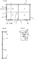
element 4 to anadjacent element 2 is shown inFIGS. 1A-1B . Theelement 4 and theadjacent element 2 may be boards of a furniture product that are connected perpendicular to each other, i.e., with a main surface of theelement 4 perpendicular to a main surface of theadjacent element 2. Anedge section 22 of theelement 4 is arranged in anedge section groove 21 of theadjacent element 2 for locking theelement 4 and theadjacent element 2 together in a first direction. The embodiment inFIG. 1A comprises aflexible tongue 30 arranged in aninsertion groove 20 in theedge section groove 21 and atongue groove 10 at theedge section 22. The embodiment inFIG. 1B comprises aflexible tongue 30 arranged in aninsertion groove 20 at theedge section 22 and atongue groove 10 in theedge section groove 21. Theflexible tongue 30 and thetongue groove 10 cooperate for locking theelement 4 and theadjacent element 2 together in a second direction, which is essentially perpendicular to the first direction. Theflexible tongue 30 is, during assembling of theelement 4 and theadjacent element 2, pushed into theinsertion groove 20 when theedge section 22 is inserted into theedge section groove 21. Theflexible tongue 30 springs back and into thetongue groove 10 when theelement 4 and theadjacent element 2 have reached a connected state. - The
element 4 may be a back piece of a bookshelf or a wardrobe closet, and theadjacent element 2 may be a board of the frame of the bookshelf of wardrobe closet. Theelement 4 may also be a bottom of a drawer and theadjacent element 2 may be a board of the frame of the drawer. Furthermore theelement 4 and theadjacent element 2 may be a first and a second board respectively of a frame of a bookshelf, a wardrobe closet or a drawer. The back piece and the bottom may be a HDF board or a particleboard with a thickness of about 2-4 mm. A back piece with a thickness less than 2 mm may be too weak to stabilize the assembled product. A back piece is for a great numbers of furniture products the largest element and a thickness over 4 mm may render the back piece cumbersome to assemble. Further embodiments may comprise one or more of the locking devices described above. The embodiments inFIGS. 1A and 1B include a calibratinggroove 40 at one side of theedge section 22. However, theedge section 22 may include a second calibrating groove at the opposing side of the edge section (see, e.g.,FIG. 6A ). -
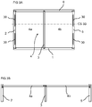
FIG. 2A shows a furniture product, such as a bookshelf, comprising eight of the locking devices, arranged with a side of the frame facing downwards. The furniture product comprises afirst element 1, e.g., a side of the bookshelf, connected at a first edge to a first edge of asecond element 2, e.g., the top of the bookshelf, by one of the locking devices. A first edge of athird element 4, e.g., a rectangular back piece of the bookshelf, is connected to a second edge of thesecond element 2 by another of the locking devices. A second edge of thethird element 4 is connected to second edge of thefirst element 1 by another of said locking devices. A first edge of afourth element 5, e.g., a bottom of the bookshelf, is connected to a third edge of thefirst element 1 by another of said locking devices. Anedge section 22 of a third edge of thethird element 4 may be arranged in anedge section groove 21 at a second edge of thefourth element 5. A first edge of afifth element 6, e.g., an opposite side of the bookshelf, is connected to a third edge of thefourth element 5, by another of said locking devices, and a third edge of thefifth element 6 is connected to a third edge of thesecond element 2, by another of said locking devices. Anedge section 22 of a fourth edge of thethird element 4 may be arranged in anedge section groove 21 at a second edge of thefifth element 6. The locking device at the first edge and the second edge, respectively, of thethird element 4 may each comprise two or moreflexible tongues 30. Asixth element 3, e.g., a shelf of the bookshelf, which is arranged parallel to thefirst element 1 and thefourth element 5, is connected, by another of the locking devices, at a first edge to thefirst element 1. A third edge of thesixth element 3 is connected, by another of the locking devices, to thefifth element 6. Theflexible tongue 30 of the locking device at the first edge and third edge, respectively, of thesixth element 3 is preferably arranged at theedge section 22. -
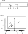
FIG. 2B shows across section CS 2B of thefirst element 1, thethird element 4 and thefifth element 6. This figure shows that anedge section 22 of the fourth edge of thethird element 4 may be arranged in theedge section groove 21 at the second edge of thefifth element 6. Thethird element 4 may comprise two ormore boards 4a-4d locked by a mechanical locking system. A second edge of thesixth element 3 may be provided with another of the locking devices (not shown) for connecting adjacent edges of adjacent boards.FIG. 4A shows an embodiment of the mechanical locking system of theboards 4a-4d. The mechanical locking system comprises atongue 60 at a first edge of a first board that cooperates with atongue groove 50 at a second edge of a second board for locking the first and the second boards in a first direction. Furthermore, the locking system comprises a protrudingstrip 70 with a lockingelement 71 at the second edge. The lockingelement 71 cooperates with a lockinggroove 80 at the first edge for locking the first and the second boards in a second direction, which is perpendicular to the first direction. The boards and the locking system are preferably arranged in the assembled product, with the lockingstrip 70 facing the direction that is to be loaded. The locking system may remain locked if arranged in this way. -
FIG. 2C shows across section CS 2C of the second andthird elements third element 4 is, in this embodiment, provided with a dismantlinggroove 33 adapted for insertion of a dismantling tool (not shown), which pushes theflexible tongue 30 into theinsertion groove 20, which facilitates dismantling of the second andthird elements -
FIG. 3A shows a furniture product not according to the invention, such as a bookshelf, comprising eight of the locking devices, arranged with a side of the frame facing downwards. The furniture product comprises afirst element 1, e.g., a side of the bookshelf, connected at a first edge to a first edge of asecond element 2, e.g., the top of the bookshelf, by one of the locking devices. A first edge of athird element 4, e.g., a rectangular back piece of the bookshelf, is connected to a second edge of thesecond element 2 by another of the locking devices. Anedge section 22 of a second edge of thethird element 4 may be inserted into anedge section groove 21 of a second edge of thefirst element 1. A first edge of afourth element 5, e.g., a bottom of the bookshelf, is connected to a third edge of thefirst element 1 by another of said locking devices. A third edge of thethird element 4 is connected to a second edge of thefourth element 5 by another of said locking devices. A first edge of afifth element 6, e.g., a side of the bookshelf, is connected to a third edge of thefourth element 5, by another of said locking devices, and a third edge of thefifth element 6 is connected to a third edge of thesecond element 2 by another of said locking devices. Anedge section 22 of a fourth edge of thethird element 4 may be arranged in anedge section groove 21 at a second edge of thefifth element 5. The locking device at the first and the third edges, respectively, of thethird element 4 may each comprise two or moreflexible tongues 30. Asixth element 3, e.g., a shelf of the bookshelf, which is arranged parallel to the first and thefourth elements first element 1, and a third edge of thesixth element 3 is connected, by another of the locking devices, to thefifth element 6. Theflexible tongue 30 of the locking device at the first and third edges, respectively, of thesixth element 3 is preferably arranged at theedge section 22. Thethird element 4 is preferably connected slideable at the first and the third edges in order to facilitate disassembling. -
FIG. 3B shows across section CS 3B of thefirst element 1, thethird element 4 and thefifth element 6. Thethird element 4 may comprise two ormore boards -
FIG. 4B shows an embodiment of a method for assembling the product described inFIGS. 2A-2C . Thefirst element 1, second element 2andsixth element 3 are preferably connected to each other before thethird element 4 is connected to the product. Thethird element 4 may be displaced in adiagonal direction 41 such that the first edge and the second edge of thethird element 4 is connected at the same time to the second edge of thefirst element 1 and to the second edge of thesecond element 2. An alternative is to displace thethird element 4 in afirst direction 42 perpendicular to thefirst element 1 and subsequently displace thethird element 4 in asecond direction 43 perpendicular to thesecond element 2. The first edge of thethird element 4 is in this embodiment connected displaceable at the first edge. Another alternative is to displace thethird element 4 in thesecond direction 43 perpendicular to thesecond element 2 and subsequently displace thethird element 4 in thefirst direction 43 perpendicular to thefirst element 1. The second edge of thethird element 4 is in this embodiment connected displaceable at the second edge. Further, the connectedfirst element 1,second element 2 andsixth element 3 can together be displaced diagonally opposite to thedirection 41 such that the second edge of thefirst element 1 and the second edge of thesecond element 2 are connected at the same time to the first edge and the second edge of thethird element 4. -
FIG. 5A shows a furniture product not according to the invention, such as a drawer, comprising six of the locking devices, arranged with a side of the frame facing downwards. The furniture product comprises afirst element 1, e.g., an inner side of the drawer, connected at a first edge to a first edge of asecond element 2, e.g., a side of the drawer, by one of the locking devices. A first edge of athird element 4, e.g., a rectangular bottom of the drawer, is connected to a second edge of thesecond element 2 by another of the locking devices. Anedge section 22 of a second edge of thethird element 4 may be inserted into anedge section groove 21 of a second edge of thefirst element 1. A first edge of afourth element 5, e.g., a side of the drawer, is connected to a third edge of thefirst element 1 by another of said locking devices. A third edge of thethird element 4 is connected to a second edge of thefourth element 5 by another of said locking devices. A first edge of afifth element 6, e.g., a front panel of the drawer, is subsequently connected to a third edge of thefourth element 5 by another of said locking devices, and a third edge of thefifth element 6 is connected to a third edge of thesecond element 2 by another of said locking devices. Thefifth element 6 may be connected in the same factory in which the first throughfourth elements edge section 22 of a fourth edge of thethird element 4 may be arranged in anedge section groove 21 at a second edge of thefifth element 5. The locking device at the first edge and the third edge, respectively, of thethird element 4 may each comprise two or moreflexible tongues 30. Thethird element 4 is preferably connected slideable at the first edge and the third edge in order to facilitate disassembling. - The fifth element 6 (front panel) may be displaced during connection in a
direction 44 perpendicular to the fourth edge of thethird element 4, and to the third edges of the second andfourth elements FIG. 4B . -
FIG. 5B shows that the corner section between, for instance, thefirst element 1 and thesecond element 2 may be provide with acover plate 91, in order to hide the locking device. -
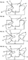
FIGS. 6A-6D show alternative embodiments of the locking device. In these embodiments, a calibratinggroove 40 may be provided at one or two sides of theedge section 22. Thetongue groove 10 may be symmetric at upper and lower parts of the groove such that the same dismantling tool (not shown) can be used at opposite positions of the locking device, i.e., mirror inverted locking devices. Theedge section groove 21 may be provided with a guidingsurface 32 that facilitates insertion of theedge section 22 into theedge section groove 21. Theedge section groove 21 may be provided with twoopposite tongue grooves 10 as shown inFIGS. 6C and 6D . The twoopposite tongue grooves 10 may be made by an end cutter, such as by a craftsman on site. -
FIG. 7A shows that the embodiment with twoopposite tongue grooves 10 may be provided with twoflexible tongues 30. -
FIGS. 7B-7C show disassembling of the locking device by inserting asymmetric dismantling tool 90 into asymmetric tongue groove 10. -
FIGS. 7D-7E show alternative embodiments provided with a dismantlingrecess 34. These embodiments may be an alternative to the embodiment shown inFIG. 2C , if for example, it is desired to un-lock the locking device from the inside of a furniture product, such as a drawer, a box or a bookshelf. These embodiments may also be used to connect thefifth element 6 to the second andfourth elements FIG. 5A . Thetongue 30 is arranged in theedge section groove 21 inFIG. 7E and at theedge section 22 inFIG. 7D . Theedge section 22 inFIG. 7E is provided with a dismantlingrecess 34 which adapted to accommodate adismantling tool 90. Thetongue 30 is pushed back into thedisplacement groove 20 to un-lock the locking device when the dismantlingtool 90 is inserted into the dismantlingrecess 34. The dismantlingrecess 34 may be covered by a covering plate (not shown). The embodiments with the dismantlinggroove 33 orrecess 34 are particular advantageous for embodiments which do not have atongue groove 10 that is accessible from an outer end of thetongue groove 10 for insertion of a dismantling tool. However, the embodiments with the dismantlinggroove 33 orrecess 34 may be used to connect any adjacent elements in order to facilitate disassembling.
Claims (8)
- An assembled furniture product comprising at least three elements arranged in three different planes which are essentially perpendicular to each other, including:a first element (1) connected perpendicular to a second element (2) and a third element (4) connected perpendicular to the second element, wherein the assembled product comprises one or more locking devices each comprising a flexible tongue (30) arranged in an insertion groove (20) at one of the at least three elements,wherein said flexible tongue cooperates with a tongue groove (10), at an adjacent one of the at least three elements, for locking the one element and the adjacent element together,wherein each of said locking devices comprises an edge section groove (22) at one of the elements or at the adjacent one of the elements,wherein an edge section of the other of the one element or the one adjacent element cooperates with said edge section groove for locking the one element and the one adjacent element together,characterized inthat a second edge of the second element (2) is connected to a first edge of the third element (4) by a first of said locking devices, that a second edge of the third element (4) is connected to a second edge of the first element (1) by a second of said locking devices,that a fourth edge of the third element (4) is arranged in a groove at a second edge of a fifth element (6), and the fifth element (6) is connected perpendicular to the second element (2) and to a fourth element (5),that a first edge of the fifth element (6) is connected to a third edge of the second element by a fourth one of said locking devices, and a third edge of the fifth element is connected to a third edge of the fourth element (5) by a fifth one of said locking devices, andthat a first edge of the first element (1) is connected to a first edge of the second element (2) by a sixth one of said locking devices, and a first edge of a fourth element (5) is connected to a third edge of the first element by a seventh one of said locking devices.
- The assembled product as claimed in claim 2, wherein the insertion groove, in at least one of said locking devices, extends along essentially the entire length of an edge of one of said at least three elements.
- The assembled product as claimed in any one of the preceding claims, wherein the tongue groove, in at least one of said locking devices, extends along essentially an entire length of an edge of the adjacent one of the at least three elements.
- The assembled product as claimed in any one of the preceding claims, wherein the flexible tongue, in at least one of said locking devices, is displaceable in the insertion groove.
- The assembled product, as claimed in any one of the preceding claims, wherein the edge section of the other of the one element or the one adjacent element is provided with a calibrating groove (40).
- The assembled product as claimed in any one of the preceding claims, wherein the third element is provided with a dismantling groove (33) or recess (34), said dismantling groove being adapted for insertion of a dismantling tool.
- The assembled product as claimed in any one of the preceding claims, wherein the assembled furniture product is a kitchen fixture.
- The assembled product as claimed in any one of the preceding claims, wherein the furniture product is one of a cupboard, a bookshelf and a wardrobe closet.
Priority Applications (7)
| Application Number | Priority Date | Filing Date | Title |
|---|---|---|---|
| DK18210703.7T DK3470690T3 (en) | 2013-09-16 | 2014-09-15 | ASSEMBLED PRODUCT |
| EP18210703.7A EP3470690B1 (en) | 2013-09-16 | 2014-09-15 | An assembled product |
| EP21205761.6A EP3967889A1 (en) | 2013-09-16 | 2014-09-15 | An assembled product |
| PL18210703T PL3470690T3 (en) | 2013-09-16 | 2014-09-15 | An assembled product |
| PL14843242T PL3047160T3 (en) | 2013-09-16 | 2014-09-15 | An assembled furniture product |
| SI201431151T SI3047160T1 (en) | 2013-09-16 | 2014-09-15 | An assembled furniture product |
| HRP20190458TT HRP20190458T1 (en) | 2013-09-16 | 2019-03-07 | An assembled furniture product |
Applications Claiming Priority (2)
| Application Number | Priority Date | Filing Date | Title |
|---|---|---|---|
| SE1351060 | 2013-09-16 | ||
| PCT/SE2014/051061 WO2015038059A1 (en) | 2013-09-16 | 2014-09-15 | An assembled product and a method of assembling the assembled product |
Related Child Applications (3)
| Application Number | Title | Priority Date | Filing Date |
|---|---|---|---|
| EP18210703.7A Division EP3470690B1 (en) | 2013-09-16 | 2014-09-15 | An assembled product |
| EP18210703.7A Division-Into EP3470690B1 (en) | 2013-09-16 | 2014-09-15 | An assembled product |
| EP21205761.6A Division EP3967889A1 (en) | 2013-09-16 | 2014-09-15 | An assembled product |
Publications (3)
| Publication Number | Publication Date |
|---|---|
| EP3047160A1 EP3047160A1 (en) | 2016-07-27 |
| EP3047160A4 EP3047160A4 (en) | 2017-04-19 |
| EP3047160B1 true EP3047160B1 (en) | 2019-01-09 |
Family
ID=52666036
Family Applications (3)
| Application Number | Title | Priority Date | Filing Date |
|---|---|---|---|
| EP14843242.0A Active EP3047160B1 (en) | 2013-09-16 | 2014-09-15 | An assembled furniture product |
| EP21205761.6A Pending EP3967889A1 (en) | 2013-09-16 | 2014-09-15 | An assembled product |
| EP18210703.7A Active EP3470690B1 (en) | 2013-09-16 | 2014-09-15 | An assembled product |
Family Applications After (2)
| Application Number | Title | Priority Date | Filing Date |
|---|---|---|---|
| EP21205761.6A Pending EP3967889A1 (en) | 2013-09-16 | 2014-09-15 | An assembled product |
| EP18210703.7A Active EP3470690B1 (en) | 2013-09-16 | 2014-09-15 | An assembled product |
Country Status (21)
| Country | Link |
|---|---|
| US (4) | US10451097B2 (en) |
| EP (3) | EP3047160B1 (en) |
| JP (1) | JP6396474B2 (en) |
| KR (1) | KR102250744B1 (en) |
| CN (2) | CN105518316B (en) |
| AU (1) | AU2014319008B2 (en) |
| BR (1) | BR112016005220B1 (en) |
| CA (1) | CA2922404C (en) |
| CL (1) | CL2016000500A1 (en) |
| DK (2) | DK3470690T3 (en) |
| EA (1) | EA032305B1 (en) |
| ES (2) | ES2717127T3 (en) |
| HR (2) | HRP20211821T1 (en) |
| LT (2) | LT3047160T (en) |
| MX (1) | MX369797B (en) |
| MY (1) | MY175374A (en) |
| PL (2) | PL3470690T3 (en) |
| SI (2) | SI3047160T1 (en) |
| TR (1) | TR201903765T4 (en) |
| UA (1) | UA120422C2 (en) |
| WO (1) | WO2015038059A1 (en) |
Families Citing this family (53)
| Publication number | Priority date | Publication date | Assignee | Title |
|---|---|---|---|---|
| UA109938C2 (en) | 2011-05-06 | 2015-10-26 | MECHANICAL LOCKING SYSTEM FOR CONSTRUCTION PANELS | |
| US9726210B2 (en) | 2013-09-16 | 2017-08-08 | Valinge Innovation Ab | Assembled product and a method of assembling the product |
| EA032305B1 (en) * | 2013-09-16 | 2019-05-31 | Велинге Инновейшн Аб | Assembled product |
| AU2014376416B2 (en) | 2014-01-10 | 2019-08-29 | Valinge Innovation Ab | A furniture panel |
| US9714672B2 (en) | 2014-01-10 | 2017-07-25 | Valinge Innovation Ab | Panels comprising a mechanical locking device and an assembled product comprising the panels |
| BR112016025783B1 (en) | 2014-05-09 | 2022-02-01 | Välinge Innovation AB | SET OF PANELS |
| RU2697150C2 (en) | 2014-07-11 | 2019-08-12 | Велинге Инновейшн Аб | Panel with slider |
| EP3234380B1 (en) | 2014-12-19 | 2019-09-11 | Välinge Innovation AB | Panels comprising a mechanical locking device |
| US10670064B2 (en) | 2015-04-21 | 2020-06-02 | Valinge Innovation Ab | Panel with a slider |
| JP6713486B2 (en) | 2015-04-30 | 2020-06-24 | ベーリンゲ、イノベイション、アクチボラグVaelinge Innovation Ab | Panel with fastening device |
| CA2998878A1 (en) | 2015-09-22 | 2017-03-30 | Valinge Innovation Ab | Panels comprising a mechanical locking device and an assembled product comprising the panels |
| KR20180090838A (en) | 2015-12-03 | 2018-08-13 | 뵈린게 이노베이션 에이비이 | Panels comprising mechanical locks and assembled products containing such panels |
| EA039168B1 (en) * | 2016-01-26 | 2021-12-13 | Велинге Инновейшн Аб | Set of panels to obtain a furniture product |
| CN108496013B (en) | 2016-02-04 | 2020-06-02 | 瓦林格创新股份有限公司 | Set of panels for assembling products |
| CA3011703A1 (en) | 2016-02-09 | 2017-08-17 | Valinge Innovation Ab | Element and method for providing dismantling groove |
| BR112018014107A2 (en) * | 2016-02-09 | 2018-12-11 | Vaelinge Innovation Ab | set of three panel-shaped elements |
| HUE053138T2 (en) | 2016-02-15 | 2021-06-28 | Vaelinge Innovation Ab | A method for forming a panel for a furniture product |
| US10933592B2 (en) | 2016-06-29 | 2021-03-02 | Valinge Innovation Ab | Method and device for inserting a tongue |
| WO2018004438A1 (en) | 2016-06-29 | 2018-01-04 | Välinge Innovation AB | Method and device for inserting a tongue |
| CN109415906B (en) | 2016-06-29 | 2021-11-05 | 瓦林格创新股份有限公司 | Method and apparatus for managing and separating a tongue from a tongue blank |
| CN109311179B (en) | 2016-06-30 | 2021-09-17 | 瓦林格创新股份有限公司 | Device for inserting a tongue |
| CN117703894A (en) * | 2016-10-27 | 2024-03-15 | 瓦林格创新股份有限公司 | Panel assembly with mechanical locking means |
| DE102016225610A1 (en) * | 2016-12-20 | 2018-06-21 | BSH Hausgeräte GmbH | Door racks with a base latched to a base and household refrigeration appliance with a door rack |
| US10953566B2 (en) | 2016-12-22 | 2021-03-23 | Valinge Innovation Ab | Device for inserting a tongue |
| EP3612739A4 (en) * | 2017-04-20 | 2020-12-23 | Välinge Innovation AB | Panels for an assembled product |
| EP3625464B1 (en) | 2017-05-15 | 2023-01-11 | Välinge Innovation AB | Elements and a locking device for an assembled product |
| KR20200099553A (en) | 2017-12-22 | 2020-08-24 | 뵈린게 이노베이션 에이비이 | Set of panels, method for assembling a set of panels and locking device for a furniture product |
| PL3728869T3 (en) | 2017-12-22 | 2023-03-20 | Välinge Innovation AB | A set of panels, a method for assembly of the same and a locking device for a furniture product |
| MX2020009767A (en) | 2018-03-23 | 2020-10-08 | Vaelinge Innovation Ab | Panels comprising a mechanical locking device and an assembled product comprising the panels. |
| WO2019203722A1 (en) | 2018-04-18 | 2019-10-24 | Välinge Innovation AB | Set of panels with a mechanical locking device |
| CA3096816A1 (en) | 2018-04-18 | 2019-10-24 | Valinge Innovation Ab | Symmetric tongue & t-cross |
| EP3781823B1 (en) | 2018-04-18 | 2024-04-10 | Välinge Innovation AB | Set of panels with a mechanical locking device |
| CN112292537B (en) | 2018-04-18 | 2022-11-29 | 瓦林格创新股份有限公司 | Panel group with mechanical locking device |
| US11614114B2 (en) | 2018-04-19 | 2023-03-28 | Valinge Innovation Ab | Panels for an assembled product |
| SI3844407T1 (en) | 2018-08-30 | 2024-06-28 | Vaelinge Innovation AB, | Set of panels with a mechanical locking device |
| KR20210113688A (en) * | 2019-01-29 | 2021-09-16 | 빌록스 에이비 | Connection system for furniture parts |
| EP3718437A1 (en) | 2019-04-05 | 2020-10-07 | Välinge Innovation AB | Method for assembling a piece of furniture |
| EP3834661A1 (en) | 2019-12-11 | 2021-06-16 | Välinge Innovation AB | Mechanical locking system for panels |
| EP4076090A4 (en) | 2019-12-19 | 2023-12-27 | Välinge Innovation AB | Set of panels with a mechanical locking device |
| JP2023510876A (en) | 2020-01-22 | 2023-03-15 | ベーリンゲ、イノベイション、アクチボラグ | A set of panels with mechanical locking devices |
| EP3871560A1 (en) | 2020-02-26 | 2021-09-01 | Välinge Innovation AB | Set of panels with a mechanical locking device |
| EP3871559A1 (en) | 2020-02-26 | 2021-09-01 | Välinge Innovation AB | Set of panels with a mechanical locking device |
| EP4162124A4 (en) | 2020-06-05 | 2024-07-31 | Vaelinge Innovation Ab | Building panels comprising a locking device |
| CN115867171A (en) | 2020-07-17 | 2023-03-28 | 瓦林格创新股份有限公司 | Mechanical locking system for panels |
| US11891780B2 (en) * | 2020-08-15 | 2024-02-06 | Kubota Corporation | Working machine |
| WO2022124974A1 (en) | 2020-12-11 | 2022-06-16 | Välinge Innovation AB | Rail for cabinets |
| CN116685244A (en) | 2021-01-07 | 2023-09-01 | 瓦林格创新股份有限公司 | Wedge-shaped tongue slot |
| CA3207233A1 (en) | 2021-01-19 | 2022-07-28 | Valinge Innovation Ab | A set of panels, a method for assembly of the same and a locking device for a furniture product |
| CN116888333A (en) | 2021-02-03 | 2023-10-13 | 瓦林格创新股份有限公司 | Building panel comprising a locking device |
| WO2022184446A1 (en) | 2021-03-01 | 2022-09-09 | Välinge Innovation AB | Mechanical connection arrangement for panels |
| WO2023059248A1 (en) * | 2021-10-04 | 2023-04-13 | Välinge Innovation AB | Mechanical connection arrangement for panels |
| WO2024158335A1 (en) * | 2023-01-27 | 2024-08-02 | Välinge Innovation AB | Cabinet assembly arrangement |
| WO2024158334A1 (en) * | 2023-01-27 | 2024-08-02 | Välinge Innovation AB | A connection arrangement for panels |
Family Cites Families (336)
| Publication number | Priority date | Publication date | Assignee | Title |
|---|---|---|---|---|
| DE228872C (en) | ||||
| US291032A (en) | 1884-01-01 | Isaac g- | ||
| US634581A (en) | 1898-11-21 | 1899-10-10 | Robert H Miller | Carpenter's square. |
| US701000A (en) | 1901-07-31 | 1902-05-27 | Carl F W Ahrens | File-cabinet. |
| US861911A (en) | 1905-11-04 | 1907-07-30 | William Stewart | Joint for articles of furniture or woodwork. |
| US881673A (en) | 1907-03-11 | 1908-03-10 | Arthur L Ellison | Wardrobe or safe. |
| US1534468A (en) | 1922-10-30 | 1925-04-21 | Jr John J Shea | Joint structure |
| US1533099A (en) | 1924-07-14 | 1925-04-14 | Robert E Carroll | Square-corner glue joint |
| GB245332A (en) | 1925-05-04 | 1926-01-07 | George Hugh Foster | An improved dowelled joint for woodwork and the like |
| US1671562A (en) * | 1925-12-21 | 1928-05-29 | Hoover Co | Suction cleaner |
| US1800386A (en) | 1926-08-28 | 1931-04-14 | Andrew Hoffman Mfg Company | Display rail |
| US1800387A (en) | 1926-12-30 | 1931-04-14 | Andrew Hoffman Mfg Company | Article-supporting device |
| US1802245A (en) | 1930-08-26 | 1931-04-21 | Clarence L Foretich | Display stand and shelving |
| US1954242A (en) * | 1932-07-28 | 1934-04-10 | Thomas E Heppenstall | Dovetail spring joint |
| US2360451A (en) * | 1942-06-02 | 1944-10-17 | Stone Abraham | Collapsible clothing container |
| US2362904A (en) | 1943-01-20 | 1944-11-14 | Allied Purchasing Corp | Joint for demountable furniture |
| US2333353A (en) * | 1943-04-06 | 1943-11-02 | Zanella Apollony | Bed reading rack |
| US2496184A (en) | 1946-06-11 | 1950-01-31 | Canon Paul L Von | Furniture drawer construction and method |
| US2517187A (en) * | 1948-03-04 | 1950-08-01 | Mac Lachlan Hats Ltd Inc | Hat crown corrugating machine |
| US2681483A (en) | 1948-10-14 | 1954-06-22 | Morawetz Hugo | Dowel connection |
| DE1062499B (en) | 1955-08-09 | 1959-07-30 | Waldes Kohinoor Inc | Oval spring ring |
| DE1107910B (en) | 1957-03-26 | 1961-05-31 | Curt Weinert | Flexible duebel |
| CH365507A (en) | 1958-11-17 | 1962-11-15 | Antonius Bus Johannes | Device for connecting perpendicular walls with automatic locking, in particular furniture walls |
| US3002630A (en) | 1960-05-24 | 1961-10-03 | Robert E Heisser | Toothbrush rack |
| US3195968A (en) | 1962-12-06 | 1965-07-20 | Lok Trim Corp | Knock-down furniture |
| DE1240638B (en) | 1963-03-07 | 1967-05-18 | Kueche | Dismountable furniture |
| GB1022377A (en) | 1963-08-19 | 1966-03-09 | Trepatent As | Arrangement of building sections for cupboards, benches or other equipment |
| US3313054A (en) | 1965-06-09 | 1967-04-11 | Poster Products Inc | Display devices |
| IS831B6 (en) | 1965-10-28 | 1973-04-12 | Nordischer Maschinenbau Rud. BaaderNordischer Maschinenbau, Rud. Baader | Method of removing the liver from the fishToys to decapitate the highly cut fish so that the wet bone remains on the fish |
| FR1481401A (en) * | 1966-05-26 | 1967-05-19 | Amco Eng | structural elements for the assembly of various assemblies such as racks, shelves and the like |
| US3410441A (en) | 1966-06-29 | 1968-11-12 | Jeff S. Rhyne | Container |
| US3347610A (en) | 1966-07-28 | 1967-10-17 | Pilliod Cabinet Company | Cabinet construction |
| FR1597173A (en) | 1968-12-26 | 1970-06-22 | ||
| DE1955922C3 (en) | 1969-11-06 | 1974-01-10 | Hefendehl, Hansfriedrich, 5893 Kierspe | Box furniture made of plastic |
| US3722704A (en) | 1970-07-23 | 1973-03-27 | Castelli Sas Anonima | Structural components for the composition of disassemblable pieces offurniture |
| US3765465A (en) | 1972-01-05 | 1973-10-16 | Deutsch Fastener Corp | Retractable captive fastener |
| US3742807A (en) | 1972-02-03 | 1973-07-03 | D Manning | Leveling and locking pin |
| JPS5232381Y2 (en) * | 1972-05-30 | 1977-07-23 | ||
| GB1398187A (en) * | 1972-06-22 | 1975-06-18 | Schreiber Furniture | Kitchen cabinets |
| US3884002A (en) | 1973-03-15 | 1975-05-20 | American Store Equip | Partition system |
| DE2414104A1 (en) | 1974-03-23 | 1975-10-09 | Alfer Alu Fertigbau | Fastener for wooden shelving - comprises straight locking pins engaged by pressure of support plate |
| DE2514357C3 (en) | 1974-04-02 | 1979-03-22 | Takeshi Tokio Shimizu | Fitting for the pivotable connection of a furniture panel with a fixed furniture part |
| US3885845A (en) | 1974-06-27 | 1975-05-27 | Hans Krieks | Knock-down furniture system |
| IT1023686B (en) * | 1974-09-06 | 1978-05-30 | Hauner C | STRUCTURE WITH COMPONIBLE ELEMENTS PARTICULARLY TO CONSTITUTE LIBRARY SHELVES OR COMPOSITE MOBILE SHELVES WITH MORE COMPARTMENTS |
| US3981118A (en) | 1974-10-17 | 1976-09-21 | The Goodyear Tire & Rubber Company | Clamping insert |
| PT65899B (en) | 1975-12-02 | 1978-05-18 | Heinze Fa R | MOBELSCHARNIER |
| CA1062321A (en) | 1976-05-12 | 1979-09-11 | I. T. W. Ltd. | Grommets for furniture connectors |
| DE2635237A1 (en) | 1976-08-05 | 1978-02-09 | Heinze Fa R | FURNITURE HINGE |
| JPS53113160U (en) | 1977-02-16 | 1978-09-08 | ||
| US4116510A (en) | 1977-03-03 | 1978-09-26 | Gte Automatic Electric Laboratories Incorporated | Chassis formed of sheet stock |
| US4099887A (en) | 1977-07-18 | 1978-07-11 | Einhard Mackenroth | Structural joints |
| US4222544A (en) | 1977-08-10 | 1980-09-16 | Kenneth Crowder | Picture rail apparatus |
| SE409603B (en) | 1977-12-20 | 1979-08-27 | Stockum Design Ab | CONNECTION |
| SE7809081L (en) | 1978-08-29 | 1980-03-01 | Hafa Fabriks Ab | DEVICE FOR COLLECTION OF CABINETS, MIRRORS, SHELVES AND OTHER DETAILS |
| IT1106579B (en) * | 1978-10-16 | 1985-11-11 | Mancini Paolo Emilio | MOUNTING AND UNIONING DEVICE FOR CONSTRUCTION ELEMENTS PARTICULARLY FURNITURE AND SIMILAR PANELS |
| US4211379A (en) | 1978-11-20 | 1980-07-08 | Morgan Myron B | Panelboard and mounting fixture combination |
| US4299067A (en) | 1979-10-30 | 1981-11-10 | J. C. Penney Company, Inc. | Partition connector system |
| US4308961A (en) | 1980-05-05 | 1982-01-05 | Kunce Thomas M | Article supporting structure |
| US4324517A (en) | 1980-06-16 | 1982-04-13 | Sps Technologies, Inc. | Panel fastener assembly with retainer ring |
| DE3047642A1 (en) * | 1980-12-17 | 1982-10-28 | Arturo Salice S.p.A., 22060 Novedrate, Como | CONNECTING FITTING |
| DE3103281C2 (en) | 1981-01-31 | 1984-05-10 | C + A Dick GmbH, 5275 Bergneustadt | Material cupboard |
| FR2501805A1 (en) | 1981-03-10 | 1982-09-17 | Haeusler Roland | NEW TYPE TENON AND MORTISE GENDER ASSEMBLY SYSTEM AND FURNITURE ARTICLES INCORPORATING THE SAME SYSTEM |
| FR2517187A1 (en) | 1981-12-01 | 1983-06-03 | Beaux Dominique | DETACHABLE BOX FOR FURNITURE USE |
| US4509648A (en) | 1982-07-26 | 1985-04-09 | The Stanley Works | Merchandising display system and components therefor |
| US4593734A (en) | 1983-09-26 | 1986-06-10 | M. Bosley Wright | Frame routing apparatus |
| US4629076A (en) | 1984-05-10 | 1986-12-16 | Amstore Corporation | Slatboard |
| GB2163825B (en) | 1984-08-30 | 1988-03-02 | Hettich Paul Gmbh & Co | Furniture connector |
| US4595105A (en) | 1984-09-12 | 1986-06-17 | Gold Kenneth S | Interlocking bookrack |
| US4750794A (en) * | 1984-11-21 | 1988-06-14 | Bass Cabinet Manufacturing, Inc. | Slide-fitted article of furniture |
| US4597122A (en) * | 1985-06-10 | 1986-07-01 | Hirsh Company | Free-standing drawer |
| US4615448A (en) | 1985-09-27 | 1986-10-07 | Masonite Corporation | Display panel |
| US4891897A (en) | 1985-12-12 | 1990-01-09 | Gieske Detlef J | Display panel |
| FR2597173B1 (en) | 1986-04-10 | 1988-10-07 | Forschle Andre | DEVICE FOR EASILY ASSEMBLING AND MODIFYING THE COMPOSITION OF A KITCHEN FURNITURE |
| GB8612597D0 (en) | 1986-05-23 | 1986-07-02 | George W R | Joint between members |
| FR2602013B1 (en) | 1986-07-25 | 1988-12-30 | Kapikian Jean Claude | ASSEMBLY SYSTEM OF TENON AND MORTISE TYPE EASILY MOUNTABLE AND REMOVABLE |
| US4815908A (en) | 1986-10-14 | 1989-03-28 | Avibank Mfg., Inc. | Captive panel fastener assembly |
| US4844266A (en) | 1987-07-16 | 1989-07-04 | Intercraft Industries Corporation | Display system |
| CA1297934C (en) | 1987-07-24 | 1992-03-24 | Craig Mengel | Method of and structure for the joining of substantially rigidparts together |
| US4886326A (en) | 1988-01-29 | 1989-12-12 | Tetrad Marketing/Sales Ltd. | Interlock system for ready to assemble furniture, and furniture incorporating such system |
| US4961295A (en) | 1988-03-14 | 1990-10-09 | Kosch Sr Paul | Metal slat and wall system utilizing same |
| US4817900A (en) | 1988-05-09 | 1989-04-04 | Gorrie Advertising Management Limited | Support device for use on a display wall |
| JPH0266308A (en) | 1988-08-30 | 1990-03-06 | Kazuhiro Matsui | Assembly tool |
| IT215989Z2 (en) | 1988-09-02 | 1991-03-26 | Cattarozzi Andrea | MODULAR CONTAINER MODULAR AND MANUALLY TRANSPORTABLE, FOR THE STORAGE OF SUBSTANCES, IN SPECIAL WAY FOR FOOD USE |
| NL8802459A (en) | 1988-10-07 | 1990-05-01 | Homburg Interieuren B V | SHOW WALL. |
| US4944416A (en) | 1988-11-21 | 1990-07-31 | Petersen Robert J | Light-weight slot-wall display panel |
| US5471804A (en) | 1988-11-21 | 1995-12-05 | Winter, Iv; Amos G. | Building system using prefabricated building panels and fastening components used therewith |
| US4909581A (en) | 1988-12-12 | 1990-03-20 | American Moulding & Millwork Company | Drawer construction |
| AU4637089A (en) | 1988-12-13 | 1990-07-10 | Rudolf Tanner | Connecting element for form-fitting connection |
| US5018323A (en) | 1989-05-12 | 1991-05-28 | Knud Clausen | Wall panel system |
| US5109993A (en) | 1989-10-31 | 1992-05-05 | Hutchison V James | Merchandise display system and merchandise holder therefor |
| US5138803A (en) | 1991-01-11 | 1992-08-18 | Commercial And Architectural Products, Inc. | Display panel assembly |
| US5121578A (en) | 1991-01-28 | 1992-06-16 | Holz Plastics, Inc. | Slat wall decorating system |
| JP3373511B2 (en) | 1991-04-01 | 2003-02-04 | ウォルター リンダル | Wooden frame building structure |
| US5209556A (en) * | 1991-04-01 | 1993-05-11 | Anderson Robert F | Drawer assembly |
| US5114265A (en) | 1991-04-15 | 1992-05-19 | Grisley Kenneth M | Interlocking routed joint |
| US5299509A (en) | 1991-07-29 | 1994-04-05 | Ballard Donald M | Connectors for shelves and bins |
| US5125518A (en) | 1991-08-12 | 1992-06-30 | Innovative Accessories | Interlocking hanging system |
| CH684284A5 (en) | 1991-09-03 | 1994-08-15 | Edgar Probst | Rear wall fitting. |
| US5212925A (en) | 1991-11-21 | 1993-05-25 | Mcclinton John | Wall corner composite, mold and method for producing glazed unit for such |
| US5360121A (en) | 1992-08-07 | 1994-11-01 | Commerical And Architectural Products, Inc. | Slotted display wall panel |
| JP2530326Y2 (en) | 1992-08-24 | 1997-03-26 | 株式会社イトーキクレビオ | Device for connecting members in furniture etc. |
| CH685276A5 (en) | 1992-11-25 | 1995-05-31 | Werner Schmidt | Building elements for assembling shelves, cupboards and walling |
| ZA94676B (en) | 1993-02-03 | 1994-08-03 | Rohm & Haas | Reduction of microfoam in spray-applied waterborne composition. |
| US5423155A (en) | 1993-06-02 | 1995-06-13 | Darko Company, Inc. | Panel for resurfacing slat walls |
| US5499667A (en) | 1994-06-21 | 1996-03-19 | Nakanishi Construction Company | Drill/cutting bit, and method of making structural joint |
| AT400611B (en) | 1993-09-30 | 1996-02-26 | Kreutzinger Johann | Connecting and attachment element |
| US5527103A (en) | 1993-10-01 | 1996-06-18 | Pittman; Charles | Cabinet of improved design and construction |
| US5375802A (en) | 1993-11-17 | 1994-12-27 | Bill Branham Designs, Ltd. | Structure for fastening facing structural units |
| US5451102A (en) | 1994-01-13 | 1995-09-19 | Chuan; Yuan-Jung | Cabinet with connecting mechanism for two adjacent wall plate |
| US5499886A (en) | 1994-03-02 | 1996-03-19 | Sauder Woodworking Co. | Coupling assembly for furniture components |
| DE4410901A1 (en) | 1994-03-29 | 1995-10-05 | Licentia Gmbh | Fridge with refrigerated goods shelves |
| JPH08166005A (en) * | 1994-03-30 | 1996-06-25 | Uotani Seisakusho:Kk | Pipe connecting device |
| US5507331A (en) | 1994-06-21 | 1996-04-16 | Nakanishi Construction Company | Drilling/cutting bit, and method of making joint |
| DE9417168U1 (en) | 1994-10-26 | 1995-02-09 | Seeland, Peter, 37130 Gleichen | Kit for a piece of furniture |
| US5536108A (en) | 1995-02-27 | 1996-07-16 | Kval, Inc. | Low cohesion material joint |
| SE9500810D0 (en) | 1995-03-07 | 1995-03-07 | Perstorp Flooring Ab | Floor tile |
| DK9500332U3 (en) | 1995-08-29 | 1996-12-27 | Ikea Of Sweden Ab | Corner assembly between the end portions of two board-like items |
| US5658086A (en) | 1995-11-24 | 1997-08-19 | Brokaw; Paul E. | Furniture connector |
| US5775521A (en) | 1996-03-22 | 1998-07-07 | Custom Plastics, Inc. | Office organizer |
| CA2207533A1 (en) | 1996-06-12 | 1997-12-12 | David P. Thurston | Adjustable hanger system |
| US5950389A (en) | 1996-07-02 | 1999-09-14 | Porter; William H. | Splines for joining panels |
| US5810505A (en) | 1996-07-26 | 1998-09-22 | Kimball International, Inc. | Double threaded fastener system |
| GB2315988A (en) | 1996-08-07 | 1998-02-18 | Ultimate Systems Limited | Furniture with adjustable size panels |
| US5711115A (en) | 1996-10-30 | 1998-01-27 | Design Components, Inc. | Fireplace shelf and mantel support system |
| US5882098A (en) | 1996-11-22 | 1999-03-16 | Decolam, Inc. | Preassembled foldable printer stand |
| CA2200422C (en) | 1997-03-19 | 2002-05-07 | Jan B. Leurdijk | Storage track system |
| US5857304A (en) | 1997-04-07 | 1999-01-12 | Abex Display Systems | Slidable locking system for disengageable panels |
| CA2204301C (en) | 1997-05-02 | 2000-04-18 | Shang-Ming Lee | A connecting assembly for horizontal boards and wall boards of a cabinet |
| DE29714096U1 (en) | 1997-08-07 | 1998-12-03 | Dorth, Ursel, 51766 Engelskirchen | Connector system |
| NO974666L (en) | 1997-10-09 | 1999-04-12 | New Ideas | Joining device for plate-shaped structural parts, as well as measuring structure |
| US5941026A (en) | 1998-01-20 | 1999-08-24 | Storewall Llc | Slatwall display system |
| DE19805538A1 (en) | 1998-02-03 | 1999-08-12 | Montana Innovations Corp | Securing vehicle load using cams mounted on U-shaped frame |
| AT406181B (en) | 1998-02-09 | 2000-03-27 | Blum Gmbh Julius | FASTENING DEVICE FOR FASTENING SEVERAL FURNITURE FITTINGS ON ONE FURNITURE PART |
| EP1055073A2 (en) | 1998-02-11 | 2000-11-29 | IPEG GmbH | Device for joining flat elements or other components |
| DE29924630U1 (en) | 1998-02-11 | 2004-05-13 | Ipeg Gmbh - Ingenieurdienstleistungen | Securing vehicle load using cams mounted on U-shaped frame |
| US6363645B1 (en) | 1998-02-25 | 2002-04-02 | Bruce A Hunter | Insert for display panels |
| US5944294A (en) | 1998-07-06 | 1999-08-31 | Baer; Thomas C. | Mounting device in form of C-clamp mounted space from a wall |
| DE29820031U1 (en) | 1998-11-10 | 1999-02-25 | Grant, Alasdair E., 33659 Bielefeld | Form-fitting connecting device for furniture or panel elements |
| US6349507B1 (en) | 1999-03-15 | 2002-02-26 | Spectra Products Corporation | Slat wall structure with profile for different shelf support brackets and the like |
| US6547086B1 (en) | 1999-03-25 | 2003-04-15 | Russell-William, Ltd. | Display wall panel |
| IT1307424B1 (en) | 1999-04-29 | 2001-11-06 | Costa S P A A | METHOD FOR PROFILING STRIPS FOR PARQUET AND SQUARING MACHINE SUITABLE TO CREATE SUCH METHOD. |
| SE517478C2 (en) | 1999-04-30 | 2002-06-11 | Valinge Aluminium Ab | Locking system for mechanical hoisting of floorboards, floorboard provided with the locking system and method for producing mechanically foldable floorboards |
| DE29911462U1 (en) | 1999-07-02 | 1999-11-18 | Akzenta Paneele & Profile Gmbh | Fastening system for panels |
| ES2182582T3 (en) | 1999-06-30 | 2003-03-01 | Akzenta Paneele & Profile Gmbh | PANEL, AS WELL AS FIXING SYSTEM FOR PANELS. |
| DE10001076C1 (en) | 2000-01-13 | 2001-10-04 | Huelsta Werke Huels Kg | Panel element to construct floor covering; has groove and spring on opposite longitudinal sides and has groove and tongue on opposite end faces, to connect and secure adjacent panel elements |
| SE517183C2 (en) | 2000-01-24 | 2002-04-23 | Valinge Aluminium Ab | Locking system for mechanical joining of floorboards, floorboard provided with the locking system and method for making such floorboards |
| AU2001247787A1 (en) | 2000-03-24 | 2001-10-08 | Commercial And Architectural Products, Inc. | Merchandising panel display system |
| US6413007B1 (en) | 2000-05-01 | 2002-07-02 | Sauder Woodworking Co. | Joint assembly |
| US6578498B1 (en) | 2000-06-06 | 2003-06-17 | Steelcase Development Corporation | Furniture accessory kit for portable computers and the like |
| EP1349994B1 (en) | 2001-01-12 | 2007-08-15 | Välinge Aluminium AB | Flooring system comprising a plurality of mechanically joinable floorboards |
| US20050104483A1 (en) | 2001-01-13 | 2005-05-19 | Darren Saravis | Snap together connectable elements |
| US6675979B2 (en) | 2001-05-21 | 2004-01-13 | Gregory Albert Taylor | Furniture assembly system |
| DE20122553U1 (en) | 2001-08-10 | 2006-03-23 | Akzenta Paneele + Profile Gmbh | Fastening system for especially floor panels hook-in connecting system, with each connection having additional locking element preventing release of connection in direction perpendicular to plane of laid panels |
| DE10142508A1 (en) | 2001-08-30 | 2003-03-27 | Bsh Bosch Siemens Hausgeraete | Locking device and food processor equipped with this |
| SE525558C2 (en) | 2001-09-20 | 2005-03-08 | Vaelinge Innovation Ab | System for forming a floor covering, set of floorboards and method for manufacturing two different types of floorboards |
| EP1430225B1 (en) | 2001-09-26 | 2005-12-21 | Agostino Ferrari S.p.A. | Device and method for detachably connecting abutting structural parts and tie member for use to form said device |
| JP2003239921A (en) | 2002-02-20 | 2003-08-27 | Takagaki Mokuzai Kogei Kk | Joining structure by tenon and mortise |
| USD482552S1 (en) | 2002-04-03 | 2003-11-25 | Commercial And Architectural Products, Inc. | Insert for a display panel |
| ATE467015T1 (en) | 2002-04-03 | 2010-05-15 | Vaelinge Innovation Ab | FLOOR PANEL WITH INTEGRATED CONNECTING MEANS AND METHOD FOR THE PRODUCTION THEREOF |
| US6772890B2 (en) | 2002-04-03 | 2004-08-10 | Commercial And Architectural Products, Inc. | Narrow groove display panel |
| AUPS265502A0 (en) | 2002-05-30 | 2002-06-20 | Ibj Resources Pty Ltd | Mounting system |
| WO2004009452A2 (en) | 2002-07-17 | 2004-01-29 | Device Works Company | Cable organization and hardware shelving system |
| US6827028B1 (en) | 2002-12-11 | 2004-12-07 | E. Pryor Callaway | Collapsible support |
| US7228977B2 (en) | 2003-06-16 | 2007-06-12 | Whirlpool Corporation | Workroom storage system |
| CA2515536C (en) | 2003-03-06 | 2012-05-15 | Vaelinge Innovation Ab | Flooring systems and methods for installation |
| US7306299B2 (en) | 2003-03-07 | 2007-12-11 | Masterbrand Cabinets, Inc. | Semi-frameless cabinet and method for making the same |
| DE20304761U1 (en) | 2003-03-24 | 2004-04-08 | Kronotec Ag | Device for connecting building boards, in particular floor panels |
| US6971614B2 (en) | 2003-07-11 | 2005-12-06 | Jifram Extrusions, Inc. | Slatwall hanger stabilizing chip |
| KR100975937B1 (en) | 2003-09-30 | 2010-08-16 | 엘지전자 주식회사 | A mounting apparatus of door basket for refrigerator |
| US20050166516A1 (en) | 2004-01-13 | 2005-08-04 | Valinge Aluminium Ab | Floor covering and locking systems |
| SE526596C2 (en) | 2004-01-13 | 2005-10-11 | Vaelinge Innovation Ab | Floating floor with mechanical locking system that allows movement between the floorboards |
| CH696889A5 (en) | 2004-03-23 | 2008-01-15 | Vifian Moebelwerkstaette Ag | Locking element for locking of two plates, has slide surface that is provided at end of springy middle area that overlaps middle area and wedge shaped head area, and fixing area that is provided at other end of middle area |
| US20050247653A1 (en) | 2004-05-06 | 2005-11-10 | Dr. Brooks Innovations, L.L.C. | System for holding implements |
| US20060108899A1 (en) * | 2004-08-09 | 2006-05-25 | Ju-Young Jin | Storage enclosure |
| US7641414B1 (en) | 2004-09-04 | 2010-01-05 | Joyce Jared L | Furniture and joint systems |
| US7841144B2 (en) * | 2005-03-30 | 2010-11-30 | Valinge Innovation Ab | Mechanical locking system for panels and method of installing same |
| DK1650375T4 (en) | 2004-10-22 | 2011-02-28 | Vaelinge Innovation Ab | Set of floor panels |
| US7454875B2 (en) | 2004-10-22 | 2008-11-25 | Valinge Aluminium Ab | Mechanical locking system for floor panels |
| DE202004017486U1 (en) | 2004-11-11 | 2006-04-13 | Vietmeyer, Adolf | Framework for cabinet or shelf has two side panels, underbody and top end such that the upper body and the top end are connected to the side panels in the longitudinal direction by connecting elements by means of dowel pins or springs |
| GB0426634D0 (en) | 2004-12-03 | 2005-01-05 | Abbott Ooo | Display panel and display system |
| DE202004019882U1 (en) | 2004-12-20 | 2006-04-27 | Fritz Egger Gmbh & Co. | Furniture parts with connecting means |
| US7686172B2 (en) | 2005-02-14 | 2010-03-30 | Whirlpool Corporation | Storage bin |
| GB2423332B (en) | 2005-02-17 | 2009-05-27 | Arctium As | Connecting device |
| BRPI0609538A2 (en) | 2005-03-29 | 2010-04-13 | Pieter Martin Henderson | fastener to connect components and assemblies that accomplish the same |
| US20060273085A1 (en) | 2005-05-18 | 2006-12-07 | Casto Daniel A | Joint for connecting workpieces |
| US20090014401A1 (en) | 2005-05-24 | 2009-01-15 | Windquest Companies, Inc. | Slotwall mounting assembly |
| SE529076C2 (en) | 2005-07-11 | 2007-04-24 | Pergo Europ Ab | A joint for panels |
| CA2616611A1 (en) | 2005-07-28 | 2007-02-01 | Grandbay Holdings Pty Ltd | Interlocking members |
| CH698988B1 (en) | 2005-08-27 | 2009-12-31 | Lindauer Gmbh | Plate-shaped solid wood elements for cover, have profile section with groove running parallel to upper side and connected groove-shaped profile element aligned approximately perpendicular against lower side |
| DE202005019986U1 (en) | 2005-12-20 | 2006-02-23 | fif Möbel Vertriebs GmbH | Construction set for box shaped furniture comprises box elements with side walls, top-floor, lower-floor and back wall whereby walls and floors are made of identical, square plates and identical square rods, which act as connectors |
| SE530653C2 (en) | 2006-01-12 | 2008-07-29 | Vaelinge Innovation Ab | Moisture-proof floor board and floor with an elastic surface layer including a decorative groove |
| DE102006011887A1 (en) | 2006-01-13 | 2007-07-19 | Akzenta Paneele + Profile Gmbh | Blocking element, panel with separate blocking element, method of installing a panel covering of panels with blocking elements, and method and device for pre-assembling a blocking element on a panel |
| DE102006006124A1 (en) | 2006-02-10 | 2007-08-23 | Flooring Technologies Ltd. | Device for locking two building panels |
| SE533410C2 (en) * | 2006-07-11 | 2010-09-14 | Vaelinge Innovation Ab | Floor panels with mechanical locking systems with a flexible and slidable tongue as well as heavy therefore |
| US7861482B2 (en) | 2006-07-14 | 2011-01-04 | Valinge Innovation Ab | Locking system comprising a combination lock for panels |
| DE102006037614B3 (en) | 2006-08-10 | 2007-12-20 | Guido Schulte | Floor covering, has head spring pre-assembled in slot and protruding over end of slot, and wedge surface formed at slot or head spring such that head spring runs into wedge surface by shifting projecting end of head spring into slot |
| US20080042532A1 (en) * | 2006-08-16 | 2008-02-21 | Crabtree Phillip C | Cabinet system and method of assembling the same |
| US7614350B2 (en) | 2006-10-05 | 2009-11-10 | Haworth, Inc. | Wall-mounted shelf unit |
| EP1922954B1 (en) | 2006-11-14 | 2009-07-15 | Spichtig AG | Depositing and sorting device |
| SE531111C2 (en) | 2006-12-08 | 2008-12-23 | Vaelinge Innovation Ab | Mechanical locking of floor panels |
| GB2445954A (en) | 2007-01-23 | 2008-07-30 | Touac Internat Ltd | A panel joining fastener |
| US8071752B2 (en) * | 2007-01-29 | 2011-12-06 | City Of Hope | Multi-targeting short interfering RNAs |
| US7644230B1 (en) * | 2007-03-15 | 2010-01-05 | Silver Peak Systems, Inc. | Dynamic load management of network memory |
| ES2317821T3 (en) | 2007-05-08 | 2015-10-15 | Franz Baur | Means and method of joining to establish a union of a first component to a second component |
| SE533028C2 (en) | 2007-06-05 | 2010-06-15 | Rickard Olsson | Box construction and mounting method |
| US7818939B2 (en) | 2007-06-05 | 2010-10-26 | Irvin Bearinger | Snap lock joint |
| US8220217B2 (en) | 2007-07-20 | 2012-07-17 | Innovaris Ag | Flooring system |
| US7726088B2 (en) | 2007-07-20 | 2010-06-01 | Moritz Andre Muehlebach | Flooring system |
| CN101099618A (en) | 2007-07-26 | 2008-01-09 | 刘瑞东 | Mortise and tenon type furniture |
| DE102007043308B4 (en) | 2007-09-11 | 2009-12-03 | Flooring Technologies Ltd. | Device for connecting and locking two building panels, in particular floor panels |
| US8146754B2 (en) | 2007-12-07 | 2012-04-03 | Red Star Traders, Llc | Storage and organization system |
| US8505257B2 (en) | 2008-01-31 | 2013-08-13 | Valinge Innovation Ab | Mechanical locking of floor panels |
| CA2623707A1 (en) | 2008-03-07 | 2009-09-07 | Pierre Trudel | Tongue and groove profile to ease desassembly of floorboards |
| GB0808252D0 (en) | 2008-05-07 | 2008-06-11 | Self Energising Coupling Compa | Latch mechanism |
| US7717278B2 (en) | 2008-07-07 | 2010-05-18 | Jui-Chien Kao | Tool suspension device |
| DE102008035293A1 (en) | 2008-07-29 | 2010-02-04 | Gronbach Forschungs- Und Entwicklungs Gmbh & Co. Kg | Mounting article for use in e.g. home, has two aluminum profiles provided with side surfaces, at which connection bolts are inserted, where bolts exhibit recess, in which o-rings are inserted |
| US8220648B2 (en) | 2008-08-01 | 2012-07-17 | Southern Imperial, Inc. | Folded slatwall inserts |
| DE202008011589U1 (en) | 2008-09-01 | 2008-11-27 | Akzenta Paneele + Profile Gmbh | Plastic floor panel with mechanical locking edges |
| CN102239301A (en) | 2008-10-08 | 2011-11-09 | 阿姆斯特郎世界工业公司 | Flooring panel with first and second decorative surfaces |
| US20100104354A1 (en) | 2008-10-29 | 2010-04-29 | Lamar Spalding | Pinned Lock Joint |
| BE1018389A3 (en) * | 2008-12-17 | 2010-10-05 | Unilin Bvba | COMPOSITE ELEMENT, MULTI-LAYER PLATE AND PANEL-SHAPED ELEMENT FOR FORMING SUCH COMPOSITE ELEMENT. |
| US7998549B2 (en) | 2009-01-08 | 2011-08-16 | Thermwood Corporation | Structure and method of assembly thereof |
| BE1018627A5 (en) | 2009-01-16 | 2011-05-03 | Flooring Ind Ltd Sarl | FLOOR PANEL. |
| PL2391783T3 (en) | 2009-01-30 | 2018-04-30 | Välinge Innovation AB | Mechanical lockings of floor panels and a tongue blank |
| US8464408B2 (en) | 2009-06-03 | 2013-06-18 | Tracy Leigh Hazzard | Hardware for furniture assembly |
| NL2003019C2 (en) | 2009-06-12 | 2010-12-15 | 4Sight Innovation Bv | FLOOR PANEL AND FLOOR COVERAGE CONSISING OF MULTIPLE OF SUCH FLOOR PANELS. |
| KR101702689B1 (en) * | 2009-06-16 | 2017-02-06 | 큐알엔에이, 인크. | Treatment of paraoxonase 1 (pon1) related diseases by inhibition of natural antisense transcript to pon1 |
| DE102009034902B4 (en) | 2009-07-27 | 2015-10-01 | Guido Schulte | Surface made of mechanically interconnectable panels |
| RU2534578C2 (en) | 2009-07-31 | 2014-11-27 | Велинге Инновейшн Аб | Methods and systems for trimming of construction board edges |
| US8365499B2 (en) | 2009-09-04 | 2013-02-05 | Valinge Innovation Ab | Resilient floor |
| DE102009041142B4 (en) | 2009-09-14 | 2015-11-05 | System 180 Gmbh | Arrangement with wall elements, kit for an arrangement as well as wall element for a furniture |
| DE202009012917U1 (en) * | 2009-09-26 | 2011-02-10 | Fehre, Jürgen | drawer |
| EP2333353A3 (en) | 2009-12-02 | 2012-07-25 | Lolli, Paride | Longitudinal sliding joint |
| EP4092213B1 (en) | 2010-01-11 | 2023-12-13 | Välinge Innovation AB | Floor covering with interlocking design |
| BR212012016569Y1 (en) | 2010-01-12 | 2020-05-19 | Vaelinge Innovation Ab | set of floor panels that are mechanically connectable to each other along a pair of adjacent edges |
| EP2523577B1 (en) | 2010-01-13 | 2014-08-20 | Fehre Design GmbH | Drawer which can be dismantled and stacked |
| DE102010004717A1 (en) | 2010-01-15 | 2011-07-21 | Pergo (Europe) Ab | Set of panels comprising retaining profiles with a separate clip and method for introducing the clip |
| US8234830B2 (en) | 2010-02-04 | 2012-08-07 | Välinge Innovations AB | Mechanical locking system for floor panels |
| CA2786680C (en) | 2010-02-04 | 2018-06-12 | Vaelinge Innovation Ab | Mechanical locking system for floor panels and a tongue therefore |
| GB201002535D0 (en) * | 2010-02-15 | 2010-03-31 | Fgb Ltd | Improvements relating to cabinets |
| BE1019361A5 (en) | 2010-06-03 | 2012-06-05 | Unilin Bvba | COMPOSED ELEMENT. |
| EP2575542B1 (en) | 2010-06-03 | 2021-03-10 | Unilin, BV | Composed element and corner connection applied herewith |
| BR112012032790A2 (en) | 2010-06-22 | 2016-12-20 | Joinlock Pity Ltd | key and key connectors |
| US20120009383A1 (en) | 2010-07-09 | 2012-01-12 | Michael Hardesty | Method for Joining Workpieces Together and Product Made Thereby |
| US8568405B2 (en) * | 2010-10-15 | 2013-10-29 | Arthrocare Corporation | Electrosurgical wand and related method and system |
| US8911037B2 (en) | 2010-12-14 | 2014-12-16 | Tenn-Tex Plastics, Inc. | Brackets and associated components for drawer and tray slides in cabinetry |
| TWI446746B (en) * | 2010-12-21 | 2014-07-21 | Accton Technology Corp | Wireless signal access device and its remote control appliance method |
| GB201100622D0 (en) | 2011-01-14 | 2011-03-02 | Phillips Sean | Article of furniture |
| IT1403925B1 (en) | 2011-02-09 | 2013-11-08 | O M M S A S Dell Ing Roberto Mariani & C | JUNCTION DEVICE FOR PANELS OF A FURNITURE. |
| US8864407B1 (en) | 2011-03-17 | 2014-10-21 | Petter Sorum | Locking joint for joining structural members |
| UA109938C2 (en) | 2011-05-06 | 2015-10-26 | MECHANICAL LOCKING SYSTEM FOR CONSTRUCTION PANELS | |
| EP2526819A1 (en) | 2011-05-25 | 2012-11-28 | Steen Sauer | Assembling of drawer |
| US8602227B1 (en) | 2011-06-08 | 2013-12-10 | Megawall, Inc. | Slatwall panel |
| CH705082A2 (en) | 2011-06-14 | 2012-12-14 | Denz Ag | Locking element for locking arrangement for cabinets and shelf board, has arc-shaped projecting lug formed at cylindrical base body for axial holding of locking element in pan bore at base, shelf board or cover |
| BE1020044A5 (en) | 2011-06-29 | 2013-04-02 | Unilin Bvba | TRAY, TRAY CONSTRUCTION AND METHOD FOR MANUFACTURING A TRAY. |
| MY172014A (en) | 2011-07-11 | 2019-11-12 | Ceraloc Innovation Ab | Mechanical locking system for floor panels |
| US9725912B2 (en) | 2011-07-11 | 2017-08-08 | Ceraloc Innovation Ab | Mechanical locking system for floor panels |
| CA2844377C (en) | 2011-08-15 | 2019-09-03 | Valinge Flooring Technology Ab | Mechanical locking system for floor panels |
| US20130048632A1 (en) | 2011-08-29 | 2013-02-28 | Yi Hsiang Chen | Quick-disconnect storage box modular structure |
| KR101147274B1 (en) | 2011-11-09 | 2012-05-18 | 주식회사 한샘 | Method for manufacturing furniture panel |
| BE1020453A3 (en) | 2011-12-01 | 2013-10-01 | Unilin Bvba | FURNITURE AND METHOD FOR MANUFACTURING FURNITURE. |
| DE102011057018B4 (en) | 2011-12-23 | 2017-11-02 | Guido Schulte | Glueless body |
| DE102012105219A1 (en) | 2011-12-23 | 2013-06-27 | Guido Schulte | Glueless body |
| WO2013111814A1 (en) | 2012-01-27 | 2013-08-01 | Dic株式会社 | Coating composition, can coating containing same, and can inner surface coating metal material coated with said can coating |
| BE1020495A4 (en) | 2012-02-08 | 2013-11-05 | Unilin Bvba | COMPOSED ELEMENT AND CORNER CONNECTION APPLIED HEREIN. |
| US8596013B2 (en) | 2012-04-04 | 2013-12-03 | Valinge Innovation Ab | Building panel with a mechanical locking system |
| US9216541B2 (en) | 2012-04-04 | 2015-12-22 | Valinge Innovation Ab | Method for producing a mechanical locking system for building panels |
| ITBO20120281A1 (en) | 2012-05-23 | 2013-11-24 | Biesse Spa | MACHINE FOR EDGING WOODEN PANELS OR THE LIKE |
| BE1020722A3 (en) | 2012-06-01 | 2014-04-01 | Unilin Bvba | PANEL FOR FORMING A FLOOR COVERING AND METHOD FOR MANUFACTURING SUCH PANELS. |
| US9510518B2 (en) | 2012-07-11 | 2016-12-06 | Dimitri Shein | Sheet metal structure |
| DE102012013807A1 (en) | 2012-07-12 | 2014-05-15 | Kolbus Gmbh & Co. Kg | Device for grooving cardboard blank |
| DE112012006949T5 (en) | 2012-09-27 | 2015-06-11 | Whirlpool Corporation | Rail for a slot wall system |
| KR101423546B1 (en) | 2012-09-28 | 2014-07-25 | 주식회사 한샘 | panel for furniture and manufacturing method of the same |
| EP2916685B1 (en) | 2012-11-06 | 2016-11-30 | Inter IKEA Systems B.V. | Fastening device, fastening system and furniture assembly |
| DE102013100352A1 (en) | 2013-01-14 | 2014-07-17 | Guido Schulte | Glueless panel composite and method for glueless joining of two panel elements |
| WO2014121410A1 (en) | 2013-02-05 | 2014-08-14 | Luis Antonio Lira Campino | Prefabricated modular construction cell |
| US20140294498A1 (en) | 2013-04-02 | 2014-10-02 | William Robert Logan | Furniture component joining system |
| AU2014259954B2 (en) * | 2013-05-01 | 2019-11-07 | Regulus Therapeutics Inc. | MicroRNA compounds and methods for modulating miR-122 |
| WO2015015603A1 (en) | 2013-07-31 | 2015-02-05 | 株式会社白井産業 | Member-coupling structure, and assembly structure provided with same |
| US9321140B2 (en) * | 2013-08-01 | 2016-04-26 | Ford Global Technologies, Llc | System for machine grinding a crankshaft |
| DE202014100090U1 (en) | 2013-08-09 | 2014-11-13 | Paul Henke Gmbh & Co. Kg | Connection fitting for furniture parts |
| CN203424576U (en) | 2013-08-21 | 2014-02-12 | 陈世威 | Plate combined automatic locks and combined cabinet |
| CN205963417U (en) | 2013-08-30 | 2017-02-22 | 宜家供应有限公司 | Furniture module and furniture spare that forms by furniture module |
| EA032305B1 (en) | 2013-09-16 | 2019-05-31 | Велинге Инновейшн Аб | Assembled product |
| US9726210B2 (en) * | 2013-09-16 | 2017-08-08 | Valinge Innovation Ab | Assembled product and a method of assembling the product |
| GB2520927A (en) | 2013-11-13 | 2015-06-10 | Hassan Fouladi | Panel for building a structure |
| US9700157B2 (en) | 2013-12-20 | 2017-07-11 | Andreas Gesswein | Suspension device |
| DK3092415T3 (en) | 2014-01-10 | 2019-10-21 | Vaelinge Innovation Ab | PANELS INCLUDING A MECHANICAL LOCKING MECHANISM AND A COMPLETELY FITTED PRODUCT CONTAINING THE PANELS |
| AU2014376417B2 (en) | 2014-01-10 | 2018-08-09 | Valinge Innovation Ab | An assembled product and a method of assembling the product |
| US9714672B2 (en) | 2014-01-10 | 2017-07-25 | Valinge Innovation Ab | Panels comprising a mechanical locking device and an assembled product comprising the panels |
| AU2014376416B2 (en) | 2014-01-10 | 2019-08-29 | Valinge Innovation Ab | A furniture panel |
| FR3019862B1 (en) | 2014-04-11 | 2017-07-21 | Elsa Profil | SYSTEM FOR ASSEMBLING PANELS FOLLOWING A DIEDRE FOR MAKING A FURNITURE AND FURNITURE SO PRODUCED |
| BR112016025783B1 (en) | 2014-05-09 | 2022-02-01 | Välinge Innovation AB | SET OF PANELS |
| EP3146126B1 (en) * | 2014-05-14 | 2019-12-18 | Välinge Innovation AB | Set of two idencital panels with a mechanical locking system comprising a flexible tongue |
| RU2697150C2 (en) | 2014-07-11 | 2019-08-12 | Велинге Инновейшн Аб | Panel with slider |
| DE102014110124A1 (en) | 2014-07-18 | 2016-01-21 | Guido Schulte | Tongue and Federeckverbindung of two components under inclusion of an additional tongue and groove connector |
| US9938066B2 (en) | 2014-09-12 | 2018-04-10 | Sonoco Development, Inc. | Temperature controlled pallet shipper |
| US9922150B1 (en) * | 2014-11-11 | 2018-03-20 | Altera Corporation | Method and apparatus for satisfying operating conditions in a system design using an electronic design automation tool |
| EP3234380B1 (en) | 2014-12-19 | 2019-09-11 | Välinge Innovation AB | Panels comprising a mechanical locking device |
| CA2876325A1 (en) | 2014-12-31 | 2016-06-30 | Fitneff Inc. | Clip and rail attachment system |
| US10378570B2 (en) | 2015-01-07 | 2019-08-13 | Fyrn | Securing pin for securing structural members |
| US10670064B2 (en) | 2015-04-21 | 2020-06-02 | Valinge Innovation Ab | Panel with a slider |
| JP6713486B2 (en) | 2015-04-30 | 2020-06-24 | ベーリンゲ、イノベイション、アクチボラグVaelinge Innovation Ab | Panel with fastening device |
| CA2998878A1 (en) | 2015-09-22 | 2017-03-30 | Valinge Innovation Ab | Panels comprising a mechanical locking device and an assembled product comprising the panels |
| KR20180090838A (en) | 2015-12-03 | 2018-08-13 | 뵈린게 이노베이션 에이비이 | Panels comprising mechanical locks and assembled products containing such panels |
| EA039168B1 (en) | 2016-01-26 | 2021-12-13 | Велинге Инновейшн Аб | Set of panels to obtain a furniture product |
| CN108496013B (en) | 2016-02-04 | 2020-06-02 | 瓦林格创新股份有限公司 | Set of panels for assembling products |
| BR112018014107A2 (en) | 2016-02-09 | 2018-12-11 | Vaelinge Innovation Ab | set of three panel-shaped elements |
| CA3011703A1 (en) | 2016-02-09 | 2017-08-17 | Valinge Innovation Ab | Element and method for providing dismantling groove |
| HUE053138T2 (en) | 2016-02-15 | 2021-06-28 | Vaelinge Innovation Ab | A method for forming a panel for a furniture product |
| CN117703894A (en) | 2016-10-27 | 2024-03-15 | 瓦林格创新股份有限公司 | Panel assembly with mechanical locking means |
| US10953566B2 (en) | 2016-12-22 | 2021-03-23 | Valinge Innovation Ab | Device for inserting a tongue |
| DE202017101856U1 (en) | 2017-03-30 | 2017-04-27 | Häfele Berlin Gmbh & Co Kg | Backplane Einsteckkeil |
| EP3625464B1 (en) | 2017-05-15 | 2023-01-11 | Välinge Innovation AB | Elements and a locking device for an assembled product |
| KR20200099553A (en) | 2017-12-22 | 2020-08-24 | 뵈린게 이노베이션 에이비이 | Set of panels, method for assembling a set of panels and locking device for a furniture product |
| PL3728869T3 (en) | 2017-12-22 | 2023-03-20 | Välinge Innovation AB | A set of panels, a method for assembly of the same and a locking device for a furniture product |
| MX2020009767A (en) | 2018-03-23 | 2020-10-08 | Vaelinge Innovation Ab | Panels comprising a mechanical locking device and an assembled product comprising the panels. |
| EP3781823B1 (en) | 2018-04-18 | 2024-04-10 | Välinge Innovation AB | Set of panels with a mechanical locking device |
| WO2019203722A1 (en) | 2018-04-18 | 2019-10-24 | Välinge Innovation AB | Set of panels with a mechanical locking device |
| CN112292537B (en) | 2018-04-18 | 2022-11-29 | 瓦林格创新股份有限公司 | Panel group with mechanical locking device |
| CA3096816A1 (en) | 2018-04-18 | 2019-10-24 | Valinge Innovation Ab | Symmetric tongue & t-cross |
| US11614114B2 (en) | 2018-04-19 | 2023-03-28 | Valinge Innovation Ab | Panels for an assembled product |
| SI3844407T1 (en) | 2018-08-30 | 2024-06-28 | Vaelinge Innovation AB, | Set of panels with a mechanical locking device |
| AU2019330606A1 (en) | 2018-08-30 | 2021-03-04 | Välinge Innovation AB | Set of panels with a mechanical locking device |
| EP3730807A1 (en) | 2019-04-26 | 2020-10-28 | Välinge Innovation AB | Set of panels with a mechanical locking device |
| EP3834661A1 (en) | 2019-12-11 | 2021-06-16 | Välinge Innovation AB | Mechanical locking system for panels |
| EP4076090A4 (en) | 2019-12-19 | 2023-12-27 | Välinge Innovation AB | Set of panels with a mechanical locking device |
| JP2023510876A (en) | 2020-01-22 | 2023-03-15 | ベーリンゲ、イノベイション、アクチボラグ | A set of panels with mechanical locking devices |
| KR20200000564U (en) * | 2020-02-20 | 2020-03-11 | 한보일렉트(주) | A Joint for Connecting Pipes |
| EP3871560A1 (en) | 2020-02-26 | 2021-09-01 | Välinge Innovation AB | Set of panels with a mechanical locking device |
| EP3871559A1 (en) | 2020-02-26 | 2021-09-01 | Välinge Innovation AB | Set of panels with a mechanical locking device |
| EP3875195A1 (en) | 2020-03-03 | 2021-09-08 | Välinge Innovation AB | Machine for producing two or more holes in a surface of a panel |
| EP4162124A4 (en) | 2020-06-05 | 2024-07-31 | Vaelinge Innovation Ab | Building panels comprising a locking device |
| CN115867171A (en) | 2020-07-17 | 2023-03-28 | 瓦林格创新股份有限公司 | Mechanical locking system for panels |
| WO2022035368A1 (en) | 2020-08-12 | 2022-02-17 | Välinge Innovation AB | Panels with edge reinforcement and a method for producing a panel with such a reinforcement |
| WO2022124974A1 (en) | 2020-12-11 | 2022-06-16 | Välinge Innovation AB | Rail for cabinets |
-
2014
- 2014-09-15 EA EA201690543A patent/EA032305B1/en not_active IP Right Cessation
- 2014-09-15 AU AU2014319008A patent/AU2014319008B2/en active Active
- 2014-09-15 SI SI201431151T patent/SI3047160T1/en unknown
- 2014-09-15 EP EP14843242.0A patent/EP3047160B1/en active Active
- 2014-09-15 CN CN201480049689.5A patent/CN105518316B/en active Active
- 2014-09-15 PL PL18210703T patent/PL3470690T3/en unknown
- 2014-09-15 ES ES14843242T patent/ES2717127T3/en active Active
- 2014-09-15 HR HRP20211821TT patent/HRP20211821T1/en unknown
- 2014-09-15 CN CN201910180609.4A patent/CN109854597B/en active Active
- 2014-09-15 MY MYPI2016700545A patent/MY175374A/en unknown
- 2014-09-15 DK DK18210703.7T patent/DK3470690T3/en active
- 2014-09-15 LT LTEP14843242.0T patent/LT3047160T/en unknown
- 2014-09-15 JP JP2016541936A patent/JP6396474B2/en active Active
- 2014-09-15 ES ES18210703T patent/ES2900005T3/en active Active
- 2014-09-15 UA UAA201603577A patent/UA120422C2/en unknown
- 2014-09-15 LT LTEP18210703.7T patent/LT3470690T/en unknown
- 2014-09-15 DK DK14843242.0T patent/DK3047160T3/en active
- 2014-09-15 CA CA2922404A patent/CA2922404C/en active Active
- 2014-09-15 TR TR2019/03765T patent/TR201903765T4/en unknown
- 2014-09-15 EP EP21205761.6A patent/EP3967889A1/en active Pending
- 2014-09-15 EP EP18210703.7A patent/EP3470690B1/en active Active
- 2014-09-15 US US14/486,681 patent/US10451097B2/en active Active
- 2014-09-15 BR BR112016005220-0A patent/BR112016005220B1/en active IP Right Grant
- 2014-09-15 KR KR1020167008955A patent/KR102250744B1/en active IP Right Grant
- 2014-09-15 PL PL14843242T patent/PL3047160T3/en unknown
- 2014-09-15 MX MX2016003112A patent/MX369797B/en active IP Right Grant
- 2014-09-15 WO PCT/SE2014/051061 patent/WO2015038059A1/en active Application Filing
- 2014-09-15 SI SI201431930T patent/SI3470690T1/en unknown
-
2016
- 2016-03-04 CL CL2016000500A patent/CL2016000500A1/en unknown
-
2019
- 2019-03-07 HR HRP20190458TT patent/HRP20190458T1/en unknown
- 2019-09-09 US US16/564,438 patent/US10731688B2/en active Active
-
2020
- 2020-06-29 US US16/915,258 patent/US11204051B2/en active Active
-
2021
- 2021-11-11 US US17/524,293 patent/US11680596B2/en active Active
Non-Patent Citations (1)
| Title |
|---|
| None * |
Also Published As
Similar Documents
| Publication | Publication Date | Title |
|---|---|---|
| US10731688B2 (en) | Assembled product and a method of assembling the assembled product | |
| US11649843B2 (en) | Assembled product and a method of assembling the product | |
| EP3501339B1 (en) | An assembled product and a method of assembling the product | |
| US10669716B2 (en) | Panels comprising a mechanical locking device and an assembled product comprising the panels | |
| US11448249B2 (en) | Panels comprising a mechanical locking device and an assembled product comprising the panels | |
| WO2015105450A1 (en) | A furniture panel |
Legal Events
| Date | Code | Title | Description |
|---|---|---|---|
| PUAI | Public reference made under article 153(3) epc to a published international application that has entered the european phase |
Free format text: ORIGINAL CODE: 0009012 |
|
| 17P | Request for examination filed |
Effective date: 20160218 |
|
| AK | Designated contracting states |
Kind code of ref document: A1 Designated state(s): AL AT BE BG CH CY CZ DE DK EE ES FI FR GB GR HR HU IE IS IT LI LT LU LV MC MK MT NL NO PL PT RO RS SE SI SK SM TR |
|
| AX | Request for extension of the european patent |
Extension state: BA ME |
|
| DAX | Request for extension of the european patent (deleted) | ||
| A4 | Supplementary search report drawn up and despatched |
Effective date: 20170317 |
|
| RIC1 | Information provided on ipc code assigned before grant |
Ipc: F16B 12/26 20060101ALI20170313BHEP Ipc: F16B 12/46 20060101ALI20170313BHEP Ipc: A47B 61/00 20060101ALI20170313BHEP Ipc: F16B 12/10 20060101AFI20170313BHEP Ipc: A47B 47/00 20060101ALI20170313BHEP Ipc: A47B 47/04 20060101ALI20170313BHEP |
|
| STAA | Information on the status of an ep patent application or granted ep patent |
Free format text: STATUS: EXAMINATION IS IN PROGRESS |
|
| 17Q | First examination report despatched |
Effective date: 20180202 |
|
| GRAP | Despatch of communication of intention to grant a patent |
Free format text: ORIGINAL CODE: EPIDOSNIGR1 |
|
| STAA | Information on the status of an ep patent application or granted ep patent |
Free format text: STATUS: GRANT OF PATENT IS INTENDED |
|
| INTG | Intention to grant announced |
Effective date: 20180725 |
|
| GRAS | Grant fee paid |
Free format text: ORIGINAL CODE: EPIDOSNIGR3 |
|
| GRAA | (expected) grant |
Free format text: ORIGINAL CODE: 0009210 |
|
| STAA | Information on the status of an ep patent application or granted ep patent |
Free format text: STATUS: THE PATENT HAS BEEN GRANTED |
|
| AK | Designated contracting states |
Kind code of ref document: B1 Designated state(s): AL AT BE BG CH CY CZ DE DK EE ES FI FR GB GR HR HU IE IS IT LI LT LU LV MC MK MT NL NO PL PT RO RS SE SI SK SM TR |
|
| REG | Reference to a national code |
Ref country code: GB Ref legal event code: FG4D |
|
| RIN1 | Information on inventor provided before grant (corrected) |
Inventor name: DERELOEV, PETER Inventor name: PALSSON, AGNE Inventor name: BRAENNSTROEM, HANS |
|
| REG | Reference to a national code |
Ref country code: CH Ref legal event code: EP Ref country code: AT Ref legal event code: REF Ref document number: 1087668 Country of ref document: AT Kind code of ref document: T Effective date: 20190115 |
|
| REG | Reference to a national code |
Ref country code: DE Ref legal event code: R096 Ref document number: 602014039739 Country of ref document: DE |
|
| REG | Reference to a national code |
Ref country code: IE Ref legal event code: FG4D |
|
| REG | Reference to a national code |
Ref country code: RO Ref legal event code: EPE |
|
| REG | Reference to a national code |
Ref country code: HR Ref legal event code: TUEP Ref document number: P20190458 Country of ref document: HR |
|
| REG | Reference to a national code |
Ref country code: DK Ref legal event code: T3 Effective date: 20190404 |
|
| REG | Reference to a national code |
Ref country code: SE Ref legal event code: TRGR |
|
| REG | Reference to a national code |
Ref country code: HR Ref legal event code: T1PR Ref document number: P20190458 Country of ref document: HR |
|
| REG | Reference to a national code |
Ref country code: EE Ref legal event code: FG4A Ref document number: E017166 Country of ref document: EE Effective date: 20190325 Ref country code: NL Ref legal event code: MP Effective date: 20190109 |
|
| REG | Reference to a national code |
Ref country code: NO Ref legal event code: T2 Effective date: 20190109 |
|
| REG | Reference to a national code |
Ref country code: ES Ref legal event code: FG2A Ref document number: 2717127 Country of ref document: ES Kind code of ref document: T3 Effective date: 20190619 |
|
| PG25 | Lapsed in a contracting state [announced via postgrant information from national office to epo] |
Ref country code: NL Free format text: LAPSE BECAUSE OF FAILURE TO SUBMIT A TRANSLATION OF THE DESCRIPTION OR TO PAY THE FEE WITHIN THE PRESCRIBED TIME-LIMIT Effective date: 20190109 |
|
| REG | Reference to a national code |
Ref country code: AT Ref legal event code: MK05 Ref document number: 1087668 Country of ref document: AT Kind code of ref document: T Effective date: 20190109 |
|
| PG25 | Lapsed in a contracting state [announced via postgrant information from national office to epo] |
Ref country code: PT Free format text: LAPSE BECAUSE OF FAILURE TO SUBMIT A TRANSLATION OF THE DESCRIPTION OR TO PAY THE FEE WITHIN THE PRESCRIBED TIME-LIMIT Effective date: 20190509 |
|
| PG25 | Lapsed in a contracting state [announced via postgrant information from national office to epo] |
Ref country code: RS Free format text: LAPSE BECAUSE OF FAILURE TO SUBMIT A TRANSLATION OF THE DESCRIPTION OR TO PAY THE FEE WITHIN THE PRESCRIBED TIME-LIMIT Effective date: 20190109 Ref country code: BG Free format text: LAPSE BECAUSE OF FAILURE TO SUBMIT A TRANSLATION OF THE DESCRIPTION OR TO PAY THE FEE WITHIN THE PRESCRIBED TIME-LIMIT Effective date: 20190409 Ref country code: GR Free format text: LAPSE BECAUSE OF FAILURE TO SUBMIT A TRANSLATION OF THE DESCRIPTION OR TO PAY THE FEE WITHIN THE PRESCRIBED TIME-LIMIT Effective date: 20190410 Ref country code: IS Free format text: LAPSE BECAUSE OF FAILURE TO SUBMIT A TRANSLATION OF THE DESCRIPTION OR TO PAY THE FEE WITHIN THE PRESCRIBED TIME-LIMIT Effective date: 20190509 |
|
| REG | Reference to a national code |
Ref country code: HR Ref legal event code: ODRP Ref document number: P20190458 Country of ref document: HR Payment date: 20190820 Year of fee payment: 6 |
|
| REG | Reference to a national code |
Ref country code: DE Ref legal event code: R097 Ref document number: 602014039739 Country of ref document: DE |
|
| PG25 | Lapsed in a contracting state [announced via postgrant information from national office to epo] |
Ref country code: AL Free format text: LAPSE BECAUSE OF FAILURE TO SUBMIT A TRANSLATION OF THE DESCRIPTION OR TO PAY THE FEE WITHIN THE PRESCRIBED TIME-LIMIT Effective date: 20190109 Ref country code: AT Free format text: LAPSE BECAUSE OF FAILURE TO SUBMIT A TRANSLATION OF THE DESCRIPTION OR TO PAY THE FEE WITHIN THE PRESCRIBED TIME-LIMIT Effective date: 20190109 |
|
| PLBE | No opposition filed within time limit |
Free format text: ORIGINAL CODE: 0009261 |
|
| STAA | Information on the status of an ep patent application or granted ep patent |
Free format text: STATUS: NO OPPOSITION FILED WITHIN TIME LIMIT |
|
| PG25 | Lapsed in a contracting state [announced via postgrant information from national office to epo] |
Ref country code: SM Free format text: LAPSE BECAUSE OF FAILURE TO SUBMIT A TRANSLATION OF THE DESCRIPTION OR TO PAY THE FEE WITHIN THE PRESCRIBED TIME-LIMIT Effective date: 20190109 |
|
| 26N | No opposition filed |
Effective date: 20191010 |
|
| PG25 | Lapsed in a contracting state [announced via postgrant information from national office to epo] |
Ref country code: MC Free format text: LAPSE BECAUSE OF FAILURE TO SUBMIT A TRANSLATION OF THE DESCRIPTION OR TO PAY THE FEE WITHIN THE PRESCRIBED TIME-LIMIT Effective date: 20190109 |
|
| PG25 | Lapsed in a contracting state [announced via postgrant information from national office to epo] |
Ref country code: LU Free format text: LAPSE BECAUSE OF NON-PAYMENT OF DUE FEES Effective date: 20190915 |
|
| REG | Reference to a national code |
Ref country code: HR Ref legal event code: ODRP Ref document number: P20190458 Country of ref document: HR Payment date: 20200903 Year of fee payment: 7 |
|
| PG25 | Lapsed in a contracting state [announced via postgrant information from national office to epo] |
Ref country code: CY Free format text: LAPSE BECAUSE OF FAILURE TO SUBMIT A TRANSLATION OF THE DESCRIPTION OR TO PAY THE FEE WITHIN THE PRESCRIBED TIME-LIMIT Effective date: 20190109 |
|
| PG25 | Lapsed in a contracting state [announced via postgrant information from national office to epo] |
Ref country code: MT Free format text: LAPSE BECAUSE OF FAILURE TO SUBMIT A TRANSLATION OF THE DESCRIPTION OR TO PAY THE FEE WITHIN THE PRESCRIBED TIME-LIMIT Effective date: 20190109 Ref country code: HU Free format text: LAPSE BECAUSE OF FAILURE TO SUBMIT A TRANSLATION OF THE DESCRIPTION OR TO PAY THE FEE WITHIN THE PRESCRIBED TIME-LIMIT; INVALID AB INITIO Effective date: 20140915 |
|
| REG | Reference to a national code |
Ref country code: HR Ref legal event code: ODRP Ref document number: P20190458 Country of ref document: HR Payment date: 20210909 Year of fee payment: 8 |
|
| PG25 | Lapsed in a contracting state [announced via postgrant information from national office to epo] |
Ref country code: MK Free format text: LAPSE BECAUSE OF FAILURE TO SUBMIT A TRANSLATION OF THE DESCRIPTION OR TO PAY THE FEE WITHIN THE PRESCRIBED TIME-LIMIT Effective date: 20190109 |
|
| REG | Reference to a national code |
Ref country code: HR Ref legal event code: ODRP Ref document number: P20190458 Country of ref document: HR Payment date: 20220913 Year of fee payment: 9 |
|
| P01 | Opt-out of the competence of the unified patent court (upc) registered |
Effective date: 20230522 |
|
| REG | Reference to a national code |
Ref country code: HR Ref legal event code: ODRP Ref document number: P20190458 Country of ref document: HR Payment date: 20230824 Year of fee payment: 10 |
|
| PGFP | Annual fee paid to national office [announced via postgrant information from national office to epo] |
Ref country code: TR Payment date: 20230823 Year of fee payment: 10 Ref country code: RO Payment date: 20230913 Year of fee payment: 10 Ref country code: NO Payment date: 20230823 Year of fee payment: 10 Ref country code: IT Payment date: 20230822 Year of fee payment: 10 Ref country code: IE Payment date: 20230823 Year of fee payment: 10 Ref country code: GB Payment date: 20230823 Year of fee payment: 10 Ref country code: FI Payment date: 20230823 Year of fee payment: 10 Ref country code: EE Payment date: 20230822 Year of fee payment: 10 Ref country code: CZ Payment date: 20230825 Year of fee payment: 10 |
|
| PGFP | Annual fee paid to national office [announced via postgrant information from national office to epo] |
Ref country code: SK Payment date: 20230830 Year of fee payment: 10 Ref country code: SI Payment date: 20230908 Year of fee payment: 10 Ref country code: SE Payment date: 20230822 Year of fee payment: 10 Ref country code: PL Payment date: 20230823 Year of fee payment: 10 Ref country code: HR Payment date: 20230824 Year of fee payment: 10 Ref country code: FR Payment date: 20230822 Year of fee payment: 10 Ref country code: DK Payment date: 20230822 Year of fee payment: 10 Ref country code: DE Payment date: 20230822 Year of fee payment: 10 Ref country code: BE Payment date: 20230822 Year of fee payment: 10 |
|
| PGFP | Annual fee paid to national office [announced via postgrant information from national office to epo] |
Ref country code: LV Payment date: 20230822 Year of fee payment: 10 Ref country code: LT Payment date: 20230822 Year of fee payment: 10 |
|
| PGFP | Annual fee paid to national office [announced via postgrant information from national office to epo] |
Ref country code: ES Payment date: 20231002 Year of fee payment: 10 |
|
| PGFP | Annual fee paid to national office [announced via postgrant information from national office to epo] |
Ref country code: CH Payment date: 20231001 Year of fee payment: 10 |