JP2015102403A5 - - Google Patents
Download PDFInfo
- Publication number
- JP2015102403A5 JP2015102403A5 JP2013242556A JP2013242556A JP2015102403A5 JP 2015102403 A5 JP2015102403 A5 JP 2015102403A5 JP 2013242556 A JP2013242556 A JP 2013242556A JP 2013242556 A JP2013242556 A JP 2013242556A JP 2015102403 A5 JP2015102403 A5 JP 2015102403A5
- Authority
- JP
- Japan
- Prior art keywords
- wiring
- electronic component
- base
- outer edge
- digital signal
- Prior art date
- Legal status (The legal status is an assumption and is not a legal conclusion. Google has not performed a legal analysis and makes no representation as to the accuracy of the status listed.)
- Granted
Links
- 238000001514 detection method Methods 0.000 claims description 42
- 239000000758 substrate Substances 0.000 description 41
- 239000002184 metal Substances 0.000 description 6
- 229910052751 metal Inorganic materials 0.000 description 6
- 230000000694 effects Effects 0.000 description 3
- PXHVJJICTQNCMI-UHFFFAOYSA-N nickel Substances [Ni] PXHVJJICTQNCMI-UHFFFAOYSA-N 0.000 description 3
- 241000251131 Sphyrna Species 0.000 description 2
- 230000005540 biological transmission Effects 0.000 description 2
- 239000011651 chromium Substances 0.000 description 2
- 239000010949 copper Substances 0.000 description 2
- 238000010586 diagram Methods 0.000 description 2
- 239000010931 gold Substances 0.000 description 2
- 102100036285 25-hydroxyvitamin D-1 alpha hydroxylase, mitochondrial Human genes 0.000 description 1
- VYZAMTAEIAYCRO-UHFFFAOYSA-N Chromium Chemical compound [Cr] VYZAMTAEIAYCRO-UHFFFAOYSA-N 0.000 description 1
- RYGMFSIKBFXOCR-UHFFFAOYSA-N Copper Chemical compound [Cu] RYGMFSIKBFXOCR-UHFFFAOYSA-N 0.000 description 1
- 101000875403 Homo sapiens 25-hydroxyvitamin D-1 alpha hydroxylase, mitochondrial Proteins 0.000 description 1
- 239000008186 active pharmaceutical agent Substances 0.000 description 1
- 229910052804 chromium Inorganic materials 0.000 description 1
- 229910052802 copper Inorganic materials 0.000 description 1
- PCHJSUWPFVWCPO-UHFFFAOYSA-N gold Chemical compound [Au] PCHJSUWPFVWCPO-UHFFFAOYSA-N 0.000 description 1
- 229910052737 gold Inorganic materials 0.000 description 1
- 229910052759 nickel Inorganic materials 0.000 description 1
- 229910052709 silver Inorganic materials 0.000 description 1
- 239000004332 silver Substances 0.000 description 1
- WFKWXMTUELFFGS-UHFFFAOYSA-N tungsten Chemical compound [W] WFKWXMTUELFFGS-UHFFFAOYSA-N 0.000 description 1
- 229910052721 tungsten Inorganic materials 0.000 description 1
- 239000010937 tungsten Substances 0.000 description 1
Description
従来から、角速度などの物理量を検出するための物理量センサーとして、特許文献1のような角速度センサーが知られている。
特許文献1に記載の角速度センサーは、パッケージと、パッケージに収容されているジャイロ素子およびICと、を有している。また、パッケージ(ベース)には複数の配線が形成されており、当該配線を介して、ICの所定の端子がジャイロ素子と電気的に接続されていたり、外部へ引き出されていたりする。より具体的には、複数の配線には、少なくとも、ジャイロ素子が有する第1の検出端子と電気的に接続されている第1検出配線と、第2の検出端子と電気的に接続されている第2検出配線と、ICへ信号を入力したり、ICから信号が出力されたりする入出力配線と、が含まれている。
Conventionally, as a physical quantity sensor for detecting a physical quantity such as an angular speed, an angular speed sensor as in Patent Document 1 is known.
The angular velocity sensor described in Patent Literature 1 includes a package, a gyro element and an IC housed in the package. In addition, a plurality of wirings are formed in the package (base), and predetermined terminals of the IC are electrically connected to the gyro element or drawn out through the wirings. More specifically, the plurality of wirings are electrically connected to at least a first detection wiring electrically connected to a first detection terminal included in the gyro element and a second detection terminal. A second detection wiring and an input / output wiring for inputting a signal to the IC and outputting a signal from the IC are included.
このような目的は、下記の本発明により達成される。
[適用例1]
本適用例のパッケージは、電子部品が配置されるベースと、
前記ベースに配置されている複数の配線と、
を有し、
前記配線は、
前記電子部品と接続される内部端子を有する複数の第1の配線と、
前記電子部品と接続される内部端子を有する複数の第2の配線と、
を有し、
前記複数の第1の配線の前記内部端子は、第1の軸に沿って並んで配置され、
前記複数の第2の配線の前記内部端子は、前記第1の軸に交差する第2の軸に沿って並んで配置され、
前記第2の配線は、物理量検出素子の検出電極に電気的に接続される検出信号配線を含み、
前記複数の第1の配線は、デジタル信号を伝送するデジタル信号配線を含み、
前記デジタル信号配線の内部端子は、前記複数の第1の配線の前記複数の内部端子における前記第1の軸方向の中央線に対して、前記第2の軸と反対側に配置されていることを特徴とする。
これにより、第1の配線と第2の配線とを離間させることができるため、第1の配線から第2の配線へのノイズ干渉を低減することができる。
Such an object is achieved by the present invention described below.
[Application Example 1]
The package of this application example includes a base on which electronic components are arranged,
A plurality of wires arranged on the base;
Have
The wiring is
A plurality of first wires having internal terminals connected to the electronic component;
A plurality of second wires having internal terminals connected to the electronic component;
Have
The internal terminals of the plurality of first wires are arranged side by side along a first axis,
The internal terminals of the plurality of second wires are arranged side by side along a second axis that intersects the first axis,
The second wiring includes a detection signal wiring electrically connected to the detection electrode of the physical quantity detection element ,
The plurality of first wirings include digital signal wirings for transmitting digital signals,
The internal terminal of the digital signal wiring is disposed on the side opposite to the second axis with respect to the center line in the first axial direction of the plurality of internal terminals of the plurality of first wirings. It is characterized by.
As a result, the first wiring and the second wiring can be separated from each other, so that noise interference from the first wiring to the second wiring can be reduced.
[適用例2]
本適用例のパッケージは、電子部品が配置されるベースと、
前記ベースに配置されている配線と、
を有し、
前記ベースは、前記ベースの平面視にて、
第1の外縁と、
前記第1の外縁の一端側に位置し、前記第1の外縁と交差する方向に延在する第2の外縁と、
を有し、
前記配線は、
前記電子部品に接続される内部端子、および前記ベースの前記第1の外縁に対応する側面に配置されている側面電極、を有する第1の配線と、
前記第2の外縁に平行な軸に沿って並んで配置され、前記電子部品と接続される内部端子を有する複数の第2の配線と、
を有し、
前記第1の配線は、デジタル信号を伝送するデジタル信号配線を含み、
前記第2の配線は、物理量検出素子の検出電極に電気的に接続される検出信号配線を含むことを特徴とする。
これにより、第1の配線と第2の配線とを離間させることができるため、第1の配線から第2の配線へのノイズ干渉を低減することができる。
[Application Example 2]
The package of this application example includes a base on which electronic components are arranged,
Wiring arranged on the base;
Have
The base is a plan view of the base,
A first outer edge;
A second outer edge located on one end side of the first outer edge and extending in a direction intersecting the first outer edge;
Have
The wiring is
A first wiring having an internal terminal connected to the electronic component and a side electrode disposed on a side surface corresponding to the first outer edge of the base;
A plurality of second wirings arranged along an axis parallel to the second outer edge and having an internal terminal connected to the electronic component;
Have
The first wiring includes a digital signal wiring for transmitting a digital signal;
The second wiring includes a detection signal wiring electrically connected to a detection electrode of the physical quantity detection element .
As a result, the first wiring and the second wiring can be separated from each other, so that noise interference from the first wiring to the second wiring can be reduced.
[適用例5]
本適用例のパッケージは、電子部品が配置されるベースと、
前記ベースに配置されている複数の配線と、
を有し、
前記複数の配線は、
前記電子部品と接続される内部端子を有する複数の第1の配線と、
前記電子部品と接続される内部端子を有する第2の配線と、
を有し、
前記複数の第1の配線は、デジタル信号を伝送するデジタル信号配線を含み、
前記第2の配線は、物理量検出素子の検出電極に電気的に接続される検出信号配線を含み、
前記デジタル信号配線と前記検出信号配線との間に、接地配線または電位が固定されている固定電位配線が配置されていることを特徴とする。
これにより、接地配線または固定電位配線がシールド層として機能するため、第1の配線から第2の配線へのノイズ干渉が低減される。
[Application Example 5]
The package of this application example includes a base on which electronic components are arranged,
A plurality of wires arranged on the base;
Have
The plurality of wirings are
A plurality of first wires having internal terminals connected to the electronic component;
A second wiring having an internal terminal connected to the electronic component;
Have
The plurality of first wirings include digital signal wirings for transmitting digital signals,
The second wiring includes a detection signal wiring electrically connected to the detection electrode of the physical quantity detection element ,
Between the digital signal wiring and the detection signal wiring, a ground wiring or a fixed potential wiring with a fixed potential is arranged.
Thereby, since the ground wiring or the fixed potential wiring functions as a shield layer, noise interference from the first wiring to the second wiring is reduced.
[適用例8]
本適用例の電子部品搭載パッケージは、上記適用例のパッケージと、
電子部品と、
を有することを特徴とする。
これにより、信頼性の高い電子部品搭載パッケージが得られる。
[Application Example 8]
The electronic component mounting package of this application example includes the package of the above application example ,
Electronic components ,
It characterized in that it has a.
Thereby, a highly reliable electronic component mounting package is obtained.
[適用例9]
本適用例の電子部品搭載パッケージは、ベースと、
前記ベースに配置された電子部品と、
前記電子部品と接続される第1の配線と、
前記電子部品と接続される第2の配線と、
前記電子部品と前記第1の配線とを接続する第1の導電性ワイヤーと、
前記電子部品と前記第2の配線とを接続する第2の導電性ワイヤーと、
を有し、
前記第1の配線は、デジタル信号を伝送するデジタル信号配線を含み、
前記第2の配線は、物理量検出素子の検出電極に電気的に接続される検出信号配線を含み、
前記ベースの平面視にて、前記デジタル信号配線に接続される前記第1の導電性ワイヤーの延在方向と、前記検出信号配線に接続される前記第2の導電性ワイヤーの延在方向とが交差していることを特徴とする。
これにより、第1の導電性ワイヤーと第2の導電性ワイヤーとを離間させることができ、第1の配線から第2の配線へのノイズ干渉が低減される。
[適用例10]
本適用例の電子部品搭載パッケージでは、前記ベースの平面視にて、前記デジタル信号配線に接続される前記第1の導電性ワイヤーの前記延在方向と、前記検出信号配線に接続される前記第2の導電性ワイヤーの前記延在方向とが直交していることが好ましい。
[Application Example 9]
The electronic component mounting package of this application example has a base,
An electronic component disposed on the base;
A first wiring connected to the electronic component;
A second wiring connected to the electronic component;
A first conductive wire connecting the electronic component and the first wiring;
A second conductive wire connecting the electronic component and the second wiring;
Have
The first wiring includes a digital signal wiring for transmitting a digital signal;
The second wiring includes a detection signal wiring electrically connected to the detection electrode of the physical quantity detection element ,
An extension direction of the first conductive wire connected to the digital signal wiring and an extension direction of the second conductive wire connected to the detection signal wiring in a plan view of the base It is characterized by crossing.
Thereby, a 1st conductive wire and a 2nd conductive wire can be spaced apart, and the noise interference from a 1st wiring to a 2nd wiring is reduced.
[Application Example 10]
In the electronic component mounting package of this application example, the extending direction of the first conductive wire connected to the digital signal wiring and the first connection connected to the detection signal wiring in a plan view of the base. It is preferable that the extending direction of the two conductive wires is orthogonal.
[適用例11]
本適用例の物理量センサーは、上記適用例の電子部品搭載パッケージと、
物理量検出素子と、
を有することを特徴とする。
これにより、信頼性の高い物理量センサーが得られる。
[Application Example 11]
The physical quantity sensor of this application example includes the electronic component mounting package of the above application example ,
A physical quantity detection element ;
It is characterized by having.
Thereby, a highly reliable physical quantity sensor can be obtained.
[適用例12]
本適用例の電子機器は、上記適用例の物理量センサーを備えていることを特徴とする。
これにより、信頼性の高い電子機器が得られる。
[適用例13]
本適用例の移動体は、上記適用例の物理量センサーを備えていることを特徴とする。
これにより、信頼性の高い移動体が得られる。
[Application Example 12 ]
An electronic apparatus according to this application example includes the physical quantity sensor according to the application example described above .
As a result, a highly reliable electronic device can be obtained.
[Application Example 13 ]
The moving body of this application example includes the physical quantity sensor of the above application example .
Thereby, a mobile body with high reliability is obtained.
以下、本発明のパッケージ、電子部品搭載パッケージ、物理量センサー、電子機器および移動体を添付図面に示す実施形態に基づいて詳細に説明する。
1.物理量センサー
<第1実施形態>
図1は、本発明の第1実施形態に係る物理量センサーの平面図(上面図)である。図2は、図1中のA−A線断面図である。図3は、図1に示す物理量センサーが有するジャイロ素子を示す平面図(上面図)である。図4は、図3に示すジャイロ素子の電極配置を示す平面図(上面図)である。図5は、図3に示すジャイロ素子の電極配置を示す平面図(上側から見た透過図)である。図6は、図3に示すジャイロ素子の動作を説明するための図である。図7は、(a)が第1基板の平面図(上側から見た透過図)、(b)が第2基板の平面図(上面図)である。図8は、(a)が第3基板の平面図(上面図)、(b)が第4基板の平面図(上面図)である。図9は、(a)が第5基板の平面図(上面図)、(b)が第6基板の平面図(上面図)である。図10は、ベースの平面図(上面図)である。図11は、図1に示す振動片が有する支持基板の平面図(上面図)である。図12は、支持基板とベースの接合状態を示す平面図(上面図)である。図13は、支持基板とジャイロ素子の接合状態を示す平面図(下面図)である。なお、以下では、説明の便宜上、図1中の紙面手前側および図2中の上側を「上」とも言い、図1中の紙面奥側およびお図2中の下側を「下」とも言う。また、以下では、X軸に沿った方向を「X軸方向」とも言い、Y軸に沿った方向を「Y軸方向」とも言う。
Hereinafter, a package, an electronic component mounting package, a physical quantity sensor, an electronic device, and a moving body of the present invention will be described in detail based on embodiments shown in the accompanying drawings.
1. Physical quantity sensor <First embodiment>
FIG. 1 is a plan view (top view) of the physical quantity sensor according to the first embodiment of the present invention. 2 is a cross-sectional view taken along line AA in FIG. FIG. 3 is a plan view (top view) showing a gyro element included in the physical quantity sensor shown in FIG. FIG. 4 is a plan view (top view) showing an electrode arrangement of the gyro element shown in FIG. FIG. 5 is a plan view (transmission view seen from above) showing the electrode arrangement of the gyro element shown in FIG. FIG. 6 is a diagram for explaining the operation of the gyro element shown in FIG. 7A is a plan view of the first substrate (transparent view seen from above), and FIG. 7B is a plan view of the second substrate (top view). 8A is a plan view (top view) of the third substrate, and FIG. 8B is a plan view (top view) of the fourth substrate. 9A is a plan view (top view) of the fifth substrate, and FIG. 9B is a plan view (top view) of the sixth substrate. FIG. 10 is a plan view (top view) of the base. FIG. 11 is a plan view (top view) of the support substrate included in the resonator element illustrated in FIG. 1. FIG. 12 is a plan view (top view) showing a bonded state of the support substrate and the base. FIG. 13 is a plan view (bottom view) showing a bonded state of the support substrate and the gyro element. In the following, for the sake of convenience of explanation, the front side in FIG. 1 and the upper side in FIG. 2 are also referred to as “up”, and the back side in FIG. 1 and the lower side in FIG. . In the following, the direction along the X axis is also referred to as “X axis direction”, and the direction along the Y axis is also referred to as “Y axis direction”.
以上のような電極の構成としては、導電性を有していれば特に限定されないが、例えば、Cr(クロム)、W(タングステン)などのメタライズ層(下地層)に、Ni(ニッケル)、Au(金)、Ag(銀)、Cu(銅)などの各被膜を積層した金属被膜で構成することができる。
なお、ハンマーヘッド3211、3221上に形成されている金属膜は、検出振動モードの周波数を調整するための調整膜として機能し、例えば、レーザー照射等によって金属膜の一部を除去し、第1、第2検出腕321、322の質量を調整することで、検出振動モードの周波数を調整することができる。一方、ハンマーヘッド3411、3421、3431、3441上に形成されている金属膜は、駆動振動モードの周波数を調整するための調整膜として機能し、例えば、レーザー照射等によって金属膜の一部を除去し、駆動腕341、342、343、344の質量を調整することで、駆動振動モードの周波数を調整することができる。
以上、ジャイロ素子2の構成について簡単に説明した。次に、ジャイロ素子2の駆動について簡単に説明する。
The configuration of the electrode as described above is not particularly limited as long as it has conductivity. For example, Ni (nickel), Au (metal) layer such as Cr (chromium), W (tungsten), etc. (Gold), Ag (silver), Cu (copper), etc. can be comprised by the metal film which laminated | stacked each film.
The metal film formed on the hammer heads 3211 and 3221 functions as an adjustment film for adjusting the frequency of the detection vibration mode. For example, a part of the metal film is removed by laser irradiation or the like, and the first film is removed. The frequency of the detection vibration mode can be adjusted by adjusting the mass of the second detection arms 321 and 322. On the other hand, the metal film formed on the hammer heads 3411, 3421, 3431, 3441 functions as an adjustment film for adjusting the frequency of the drive vibration mode, and for example, a part of the metal film is removed by laser irradiation or the like. Then, the frequency of the drive vibration mode can be adjusted by adjusting the mass of the drive arms 341, 342, 343, and 344.
The configuration of the gyro element 2 has been briefly described above. Next, driving of the gyro element 2 will be briefly described.
図9(b)に示すように、第1凹部611は、長軸方向に延びている一対の長辺611a、611bと、短軸方向に延びている一対の短辺611c、611dと、を有しており、さらに、各角部が丸みを帯びている。
また、図9(a)に示すように、第2凹部612は、長軸方向に延びている一対の長辺612a、612bと、端軸方向に延びている一対の短辺612c、612dと、を有しており、さらに、各角部が丸みを帯びている。また、ベース6の平面視にて、4つの辺612a〜612dは、それぞれ、第1凹部611よりも内側に位置している。また、辺612cにはベース6の外縁633側へ延びている切り欠き651、652が形成されている。
As shown in FIG. 9B, the first recess 611 has a pair of long sides 611a and 611b extending in the long axis direction and a pair of short sides 611c and 611d extending in the short axis direction. In addition, each corner is rounded.
9A, the second recess 612 includes a pair of long sides 612a and 612b extending in the major axis direction, a pair of short sides 612c and 612d extending in the end axis direction, In addition, each corner is rounded. In addition, the four sides 612 a to 612 d are located inside the first recess 611 in the plan view of the base 6. In addition, notches 651 and 652 extending toward the outer edge 633 of the base 6 are formed in the side 612c.
次に、ベース6に配置されている配線群8について図7ないし図10に基づいて詳細に説明する。図7は、(a)が第1基板6Aを上面側から見た透過図、(b)が第2基板6Bの上面図、図8は、(a)が第3基板6Cの上面図、(b)が第4基板6Dの上面図、図9は、(a)が第5基板6Eの上面図、(b)が第6基板6Fの上面図、図10は、ベース6の上面図である。 Next, the wiring group 8 arranged on the base 6 will be described in detail with reference to FIGS. 7A is a transparent view of the first substrate 6A viewed from the top surface side, FIG. 7B is a top view of the second substrate 6B, FIG. 8A is a top view of the third substrate 6C, FIG. 9B is a top view of the fourth substrate 6D, FIG . 9A is a top view of the fifth substrate 6E, FIG. 9B is a top view of the sixth substrate 6F, and FIG. .
[S2配線]
図8(b)および図9(a)に示すように、S2配線802は、その一端部にS2内部端子802aを有し、その他端部にS2接続端子802bを有している。そして、S2配線802は、S2内部端子802aにおいてIC10と電気的に接続され、S2接続端子802bにおいて第2検出信号端子432と電気的に接続されている。図10に示すように、S2内部端子802aとIC10との電気接続は、導電性ワイヤー822により行われている。一方、S2接続端子802bと第2検出信号端子432との電気接続は、支持基板9を介して行われている。
[S2 wiring]
As shown in FIGS. 8B and 9A, the S2 wiring 802 has an S2 internal terminal 802a at one end and an S2 connection terminal 802b at the other end. The S2 wiring 802 is electrically connected to the IC 10 at the S2 internal terminal 802a, and is electrically connected to the second detection signal terminal 432 at the S2 connection terminal 802b. As shown in FIG. 10, the electrical connection between the S2 internal terminal 802 a and the IC 10 is performed by a conductive wire 822. On the other hand, the electrical connection between the S2 connection terminal 802 b and the second detection signal terminal 432 is performed via the support substrate 9.
また、GND外部端子803cは、第1基板6Aの下面(ベース6の底面)であって、切り欠き649の近傍に、外縁632に沿って配置されている。
また、各基板6A〜6F上のGND配線803は、切り欠き649に形成されているGND側面電極803dや、第3基板6C〜第6基板6Fに形成されているビア803eを介して電気的に接続されている。具体的には、第6基板6Fから第5基板6Eへの配線の引き回しは、第6基板6Fに形成された複数のビア803eにより行われ、第5基板6Eから第4基板6Dへの配線の引き回しは、第5基板6Eに形成されたビア803eにより行われ、第4基板6Dから第3基板6Cへの配線の引き回しは、第4基板6Dに形成されたビア803eにより行われ、第3基板6Cから第2基板6Bへの配線引き回しおよび第2基板6Bから第1基板6Aへの配線の引き回しは、それぞれ、切り欠き649に形成されたGND側面電極803dにより行われている。なお、ビア803eは、配線に隠れて見えないが、説明の便宜上、その位置を白丸で示している。
The GND external terminal 803 c is disposed along the outer edge 632 in the vicinity of the notch 649 on the lower surface of the first substrate 6 </ b> A (the bottom surface of the base 6).
The GND wiring 803 on each of the substrates 6A to 6F is electrically connected via a GND side surface electrode 803d formed in the notch 649 and a via 803e formed in the third substrate 6C to the sixth substrate 6F. It is connected. Specifically, wiring from the sixth substrate 6F to the fifth substrate 6E is performed by a plurality of vias 803e formed in the sixth substrate 6F, and wiring from the fifth substrate 6E to the fourth substrate 6D is performed. The routing is performed by the via 803e formed on the fifth substrate 6E, and the wiring from the fourth substrate 6D to the third substrate 6C is performed by the via 803e formed on the fourth substrate 6D. The wiring routing from 6C to the second substrate 6B and the wiring routing from the second substrate 6B to the first substrate 6A are performed by GND side surface electrodes 803d formed in the notches 649 , respectively. Note that although the via 803e is hidden behind the wiring and cannot be seen, the position thereof is indicated by a white circle for convenience of explanation.
(第2の効果)
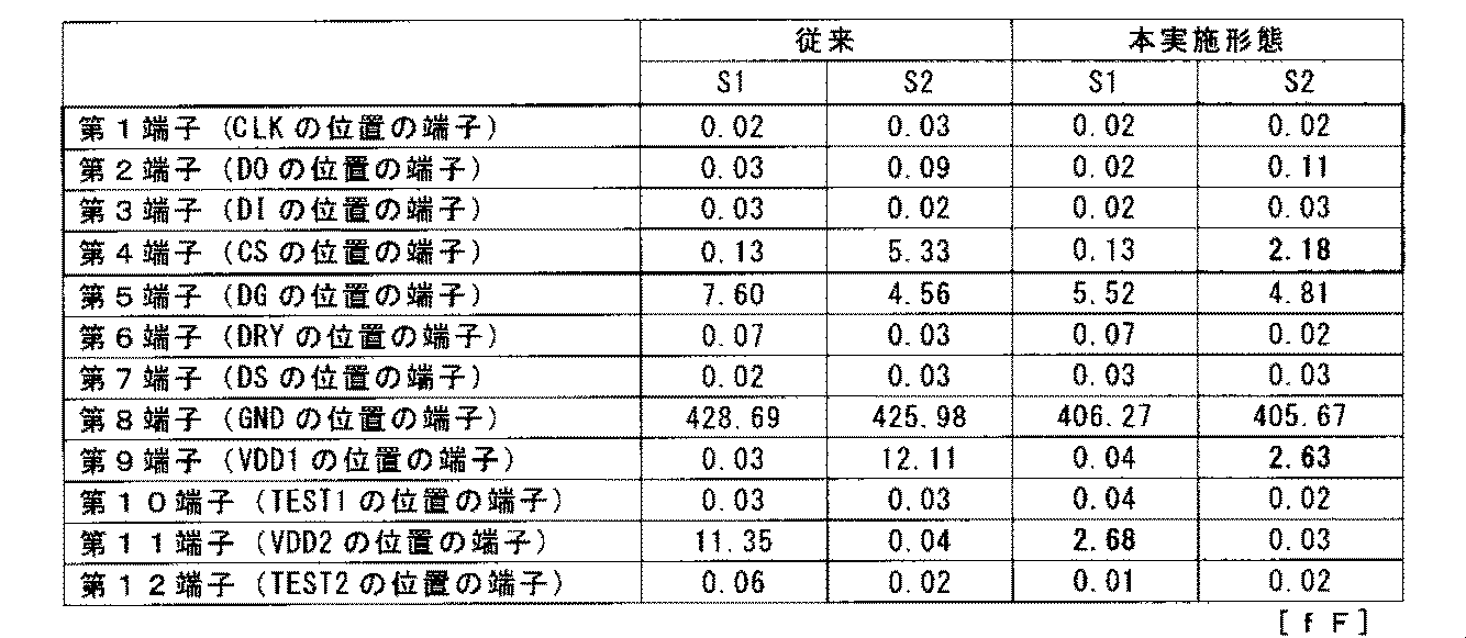
第2に、前述したように、物理量センサー1では、ベース6の外縁(第1の外縁)631、632に対応する側面631’、632’に、第1の配線が有する側面電極(803d、806c、807c、808c、809c、810c、811c、812c、813c、814c)が配置されている。これにより、S1、S2配線801、802と、各側面電極とを離間させることができる。したがって、第1の配線からS1、S2配線801、802へのノイズ干渉が低減され、高精度に角速度ωを検出することができる。特に、本実施形態では、デジタル信号配線の側面電極806c、807c、808c、809cを、S1、S2内部端子801a、802aと反対側に配置したことで、これら側面電極806c、807c、808c、809cと、S1、S2配線801、802とをより大きく離間させている。したがって、上記効果がより顕著となり、物理量センサー1は、より高精度に角速度ωを検出することができる。
(Second effect)
Secondly, as described above, in the physical quantity sensor 1, the side electrodes (803d, 806c) of the first wiring are provided on the side surfaces 631 ′, 632 ′ corresponding to the outer edges (first outer edges) 631, 632 of the base 6. 807c , 808c, 809c, 810c, 811c, 812c, 813c, 814c). Thereby, S1, S2 wiring 801 and 802 and each side electrode can be spaced apart. Therefore, noise interference from the first wiring to the S1 and S2 wirings 801 and 802 is reduced, and the angular velocity ω can be detected with high accuracy. In particular, in this embodiment, the side electrodes 806c, 807c, 808c, and 809c of the digital signal wiring are disposed on the opposite side to the S1 and S2 internal terminals 801a and 802a, so that these side electrodes 806c, 807c, 808c, and 809c , S1, S2 wirings 801, 802 are further separated from each other. Therefore, the above effect becomes more prominent, and the physical quantity sensor 1 can detect the angular velocity ω with higher accuracy.
また、前述したように、物理量センサー1では、CLK内部端子806a、DO内部端子808a、VDD1内部端子810a、VDD2内部端子814a、DRY内部端子812a、DS内部端子804a、DI内部端子807a、CS内部端子809a、TEST1内部端子811aおよびTEST2内部端子813aと、IC10とが、導電性ワイヤー824〜835で接続され、S1、S2内部端子801a、802aと、IC10とが、導電性ワイヤー821、822で接続されている。そして、物理量センサー1では、ベース6の平面視にて、導電性ワイヤー824〜835の延在方向と、導電性ワイヤー821、822の延在方向とが交差している。具体的には、導電性ワイヤー824〜835は、ベース6の短軸方向に延在しているのに対して、導電性ワイヤー821、822は、ベース6の長軸方向に延在している。すなわち、導電性ワイヤー824〜835の延在方向と、導電性ワイヤー821、822の延在方向とが直交している。このような配置とすることで、パッケージサイズを維持したまま、導電性ワイヤー821、822と、導電性ワイヤー824〜835とをなるべく大きく離間させることができる。したがって、他の配線からS1、S2配線801、802へのノイズ干渉が低減され、高精度に角速度ωを検出することができる。 As described above, in the physical quantity sensor 1, the CLK internal terminal 806a, the DO internal terminal 808a, the VDD1 internal terminal 810a , the VDD2 internal terminal 814a, the DRY internal terminal 812a, the DS internal terminal 804a, the DI internal terminal 807a, and the CS internal terminal 809a, TEST1 internal terminal 811a and TEST2 internal terminal 813a and IC10 are connected by conductive wires 824 to 835, and S1, S2 internal terminals 801a and 802a and IC10 are connected by conductive wires 821 and 822. ing. In the physical quantity sensor 1, the extending direction of the conductive wires 824 to 835 intersects the extending direction of the conductive wires 821 and 822 in the plan view of the base 6. Specifically, the conductive wires 824 to 835 extend in the minor axis direction of the base 6, while the conductive wires 821 and 822 extend in the major axis direction of the base 6. . That is, the extending direction of the conductive wires 824 to 835 is orthogonal to the extending direction of the conductive wires 821 and 822. With such an arrangement, the conductive wires 821 and 822 and the conductive wires 824 to 835 can be separated as much as possible while maintaining the package size. Therefore, noise interference from other wirings to the S1 and S2 wirings 801 and 802 is reduced, and the angular velocity ω can be detected with high accuracy.
同様に、ボンディングリード94が、S2配線802(S2内部端子802a)と重なるように配置されている。このように、S2配線802と電気的に接続されているボンディングリード94をS2配線802に近接して配置することにより、相対的に、S2配線802と電気的に接続されていない他のボンディングリード92、93をS2配線802から離間させることができる。そのため、ボンディングリード92、93からS2配線802へのノイズ干渉を低減することができる。
以上、物理量センサー1が発揮することのできる効果について説明した。
Similarly, the bonding lead 94 is disposed so as to overlap the S2 wiring 802 (S2 internal terminal 802a). As described above, by arranging the bonding lead 94 electrically connected to the S2 wiring 802 in the vicinity of the S2 wiring 802, other bonding leads that are not electrically connected to the S2 wiring 802 are relatively provided. 92 and 93 can be separated from the S2 wiring 802. Therefore, noise interference from the bonding leads 92 and 93 to the S2 wiring 802 can be reduced.
In the above, the effect which the physical quantity sensor 1 can demonstrate was demonstrated.
Claims (13)
前記ベースに配置されている複数の配線と、
を有し、
前記配線は、
前記電子部品と接続される内部端子を有する複数の第1の配線と、
前記電子部品と接続される内部端子を有する複数の第2の配線と、
を有し、
前記複数の第1の配線の前記内部端子は、第1の軸に沿って並んで配置され、
前記複数の第2の配線の前記内部端子は、前記第1の軸に交差する第2の軸に沿って並んで配置され、
前記第2の配線は、物理量検出素子の検出電極に電気的に接続される検出信号配線を含み、
前記複数の第1の配線は、デジタル信号を伝送するデジタル信号配線を含み、
前記デジタル信号配線の内部端子は、前記複数の第1の配線の前記複数の内部端子における前記第1の軸方向の中央線に対して、前記第2の軸と反対側に配置されていることを特徴とするパッケージ。 A base on which electronic components are placed;
A plurality of wires arranged on the base;
Have
The wiring is
A plurality of first wires having internal terminals connected to the electronic component;
A plurality of second wires having internal terminals connected to the electronic component;
Have
The internal terminals of the plurality of first wires are arranged side by side along a first axis,
The internal terminals of the plurality of second wires are arranged side by side along a second axis that intersects the first axis,
The second wiring includes a detection signal wiring electrically connected to the detection electrode of the physical quantity detection element ,
The plurality of first wirings include digital signal wirings for transmitting digital signals,
The internal terminal of the digital signal wiring is disposed on the side opposite to the second axis with respect to the center line in the first axial direction of the plurality of internal terminals of the plurality of first wirings. Features a package.
前記ベースに配置されている配線と、
を有し、
前記ベースは、前記ベースの平面視にて、
第1の外縁と、
前記第1の外縁の一端側に位置し、前記第1の外縁と交差する方向に延在する第2の外縁と、
を有し、
前記配線は、
前記電子部品に接続される内部端子、および前記ベースの前記第1の外縁に対応する側面に配置されている側面電極、を有する第1の配線と、
前記第2の外縁に平行な軸に沿って並んで配置され、前記電子部品と接続される内部端子を有する複数の第2の配線と、
を有し、
前記第1の配線は、デジタル信号を伝送するデジタル信号配線を含み、
前記第2の配線は、物理量検出素子の検出電極に電気的に接続される検出信号配線を含むことを特徴とするパッケージ。 A base on which electronic components are placed;
Wiring arranged on the base;
Have
The base is a plan view of the base,
A first outer edge;
A second outer edge located on one end side of the first outer edge and extending in a direction intersecting the first outer edge;
Have
The wiring is
A first wiring having an internal terminal connected to the electronic component and a side electrode disposed on a side surface corresponding to the first outer edge of the base;
A plurality of second wirings arranged along an axis parallel to the second outer edge and having an internal terminal connected to the electronic component;
Have
The first wiring includes a digital signal wiring for transmitting a digital signal;
The package, wherein the second wiring includes a detection signal wiring electrically connected to a detection electrode of the physical quantity detection element .
前記第1の配線の前記内部端子は、前記第1の外縁に平行な軸に沿って並んで配置されている請求項2に記載のパッケージ。 The first wiring is plural,
The package according to claim 2, wherein the internal terminals of the first wiring are arranged side by side along an axis parallel to the first outer edge.
前記ベースに配置されている複数の配線と、
を有し、
前記複数の配線は、
前記電子部品と接続される内部端子を有する複数の第1の配線と、
前記電子部品と接続される内部端子を有する第2の配線と、
を有し、
前記複数の第1の配線は、デジタル信号を伝送するデジタル信号配線を含み、
前記第2の配線は、物理量検出素子の検出電極に電気的に接続される検出信号配線を含み、
前記デジタル信号配線と前記検出信号配線との間に、接地配線または電位が固定されている固定電位配線が配置されていることを特徴とするパッケージ。 A base on which electronic components are placed;
A plurality of wires arranged on the base;
Have
The plurality of wirings are
A plurality of first wires having internal terminals connected to the electronic component;
A second wiring having an internal terminal connected to the electronic component;
Have
The plurality of first wirings include digital signal wirings for transmitting digital signals,
The second wiring includes a detection signal wiring electrically connected to the detection electrode of the physical quantity detection element ,
A package in which a grounding wiring or a fixed potential wiring having a fixed potential is arranged between the digital signal wiring and the detection signal wiring.
第1の外縁と、
前記第1の外縁の一端側に位置し、前記第1の外縁と交差する方向に延在する第2の外縁と、
を有し、
前記複数の第1の配線の内部端子は、前記第1の外縁と平行な第1の軸に沿って配置され、
前記第2の配線は、複数であり、
前記複数の第2の配線の内部端子は、前記第2の外縁と平行な第2の軸に沿って配置されている請求項5に記載のパッケージ。 The base is a plan view of the base,
A first outer edge;
A second outer edge located on one end side of the first outer edge and extending in a direction intersecting the first outer edge;
Have
The internal terminals of the plurality of first wirings are disposed along a first axis parallel to the first outer edge,
The second wiring is plural,
The package according to claim 5, wherein internal terminals of the plurality of second wirings are arranged along a second axis parallel to the second outer edge.
前記電子部品と、
を有することを特徴とする電子部品搭載パッケージ。 A package according to any one of claims 1 to 7;
The electronic component;
An electronic component mounting package characterized by comprising:
前記ベースに配置された電子部品と、
前記電子部品と接続される第1の配線と、
前記電子部品と接続される第2の配線と、
前記電子部品と前記第1の配線とを接続する第1の導電性ワイヤーと、
前記電子部品と前記第2の配線とを接続する第2の導電性ワイヤーと、
を有し、
前記第1の配線は、デジタル信号を伝送するデジタル信号配線を含み、
前記第2の配線は、物理量検出素子の検出電極に電気的に接続される検出信号配線を含み、
前記ベースの平面視にて、前記デジタル信号配線に接続される前記第1の導電性ワイヤーの延在方向と、前記検出信号配線に接続される前記第2の導電性ワイヤーの延在方向とが交差していることを特徴とする電子部品搭載パッケージ。 Base and
An electronic component disposed on the base;
A first wiring connected to the electronic component;
A second wiring connected to the electronic component;
A first conductive wire connecting the electronic component and the first wiring;
A second conductive wire connecting the electronic component and the second wiring;
Have
The first wiring includes a digital signal wiring for transmitting a digital signal;
The second wiring includes a detection signal wiring electrically connected to the detection electrode of the physical quantity detection element ,
An extension direction of the first conductive wire connected to the digital signal wiring and an extension direction of the second conductive wire connected to the detection signal wiring in a plan view of the base Electronic component mounting package characterized by crossing.
前記物理量検出素子と、
を有することを特徴とする物理量センサー。 The electronic component mounting package according to any one of claims 8 to 10,
The physical quantity detection element;
A physical quantity sensor characterized by comprising:
Priority Applications (3)
| Application Number | Priority Date | Filing Date | Title |
|---|---|---|---|
| JP2013242556A JP6357758B2 (en) | 2013-11-25 | 2013-11-25 | Physical quantity sensor, electronic device and mobile object |
| CN201410676341.0A CN104655117B (en) | 2013-11-25 | 2014-11-21 | Packages, physical quantity sensors, electronic equipment and mobile objects |
| US14/551,610 US9823071B2 (en) | 2013-11-25 | 2014-11-24 | Package, electronic component mounted package, physical quantity sensor, electronic device, and moving object |
Applications Claiming Priority (1)
| Application Number | Priority Date | Filing Date | Title |
|---|---|---|---|
| JP2013242556A JP6357758B2 (en) | 2013-11-25 | 2013-11-25 | Physical quantity sensor, electronic device and mobile object |
Related Child Applications (1)
| Application Number | Title | Priority Date | Filing Date |
|---|---|---|---|
| JP2018117853A Division JP6753435B2 (en) | 2018-06-21 | 2018-06-21 | Physical quantity sensors, electronics and mobiles |
Publications (3)
| Publication Number | Publication Date |
|---|---|
| JP2015102403A JP2015102403A (en) | 2015-06-04 |
| JP2015102403A5 true JP2015102403A5 (en) | 2017-01-12 |
| JP6357758B2 JP6357758B2 (en) | 2018-07-18 |
Family
ID=53181520
Family Applications (1)
| Application Number | Title | Priority Date | Filing Date |
|---|---|---|---|
| JP2013242556A Active JP6357758B2 (en) | 2013-11-25 | 2013-11-25 | Physical quantity sensor, electronic device and mobile object |
Country Status (3)
| Country | Link |
|---|---|
| US (1) | US9823071B2 (en) |
| JP (1) | JP6357758B2 (en) |
| CN (1) | CN104655117B (en) |
Families Citing this family (9)
| Publication number | Priority date | Publication date | Assignee | Title |
|---|---|---|---|---|
| JP6641874B2 (en) * | 2015-10-20 | 2020-02-05 | セイコーエプソン株式会社 | Physical quantity detection device, electronic equipment and moving object |
| JP6805697B2 (en) * | 2016-10-03 | 2020-12-23 | セイコーエプソン株式会社 | Electronic component packages, oscillators, electronics, and mobiles |
| JP6819216B2 (en) * | 2016-10-26 | 2021-01-27 | セイコーエプソン株式会社 | Gyro sensor, manufacturing method of gyro sensor, electronic device and mobile body |
| JP6926568B2 (en) * | 2017-03-24 | 2021-08-25 | セイコーエプソン株式会社 | Physical quantity sensors, electronics and mobiles |
| JP7119478B2 (en) | 2018-03-23 | 2022-08-17 | セイコーエプソン株式会社 | Circuit devices, physical quantity measuring devices, electronic devices and moving objects |
| JP2019174234A (en) * | 2018-03-28 | 2019-10-10 | セイコーエプソン株式会社 | Sensor element, sensor device, force detector, and robot |
| JP2020139879A (en) | 2019-02-28 | 2020-09-03 | セイコーエプソン株式会社 | Inertia sensors, electronics and moving objects |
| JP7251383B2 (en) * | 2019-07-29 | 2023-04-04 | セイコーエプソン株式会社 | Vibration devices, electronic equipment and moving objects |
| US11522120B1 (en) * | 2021-07-02 | 2022-12-06 | Yoketan Corp. | Micro crystal oscillator |
Family Cites Families (18)
| Publication number | Priority date | Publication date | Assignee | Title |
|---|---|---|---|---|
| JPH10284605A (en) * | 1997-04-08 | 1998-10-23 | Mitsubishi Electric Corp | Semiconductor integrated circuit and semiconductor integrated circuit layout-designed by cell-based method |
| WO2005019790A1 (en) * | 2003-08-26 | 2005-03-03 | Matsushita Electric Works, Ltd. | Sensor device |
| JP4237611B2 (en) * | 2003-12-22 | 2009-03-11 | 東芝マイクロエレクトロニクス株式会社 | Layout design method and layout design apparatus for semiconductor integrated circuit |
| JP2005241380A (en) | 2004-02-25 | 2005-09-08 | Seiko Epson Corp | Piezoelectric device, mobile phone device using piezoelectric device, and electronic apparatus using piezoelectric device |
| US20070164378A1 (en) * | 2006-01-13 | 2007-07-19 | Honeywell International Inc. | Integrated mems package |
| JP5092462B2 (en) * | 2006-06-13 | 2012-12-05 | 株式会社デンソー | Mechanical quantity sensor |
| JP5186774B2 (en) | 2007-02-15 | 2013-04-24 | セイコーエプソン株式会社 | Charge detection type sensor and package container used therefor |
| EP2011762B1 (en) * | 2007-07-02 | 2015-09-30 | Denso Corporation | Semiconductor device with a sensor connected to an external element |
| JPWO2010026817A1 (en) * | 2008-09-02 | 2012-02-02 | 株式会社村田製作所 | Tuning fork vibrator, method for manufacturing the same, and angular velocity sensor |
| JP5487672B2 (en) * | 2009-03-27 | 2014-05-07 | パナソニック株式会社 | Physical quantity sensor |
| JP5368181B2 (en) * | 2009-06-12 | 2013-12-18 | セイコーエプソン株式会社 | Physical quantity detection device, control method for physical quantity detection device, abnormality diagnosis system, and abnormality diagnosis method |
| TW201103107A (en) * | 2009-07-07 | 2011-01-16 | Jung-Tang Huang | Method for packaging micromachined devices |
| JP5552976B2 (en) * | 2010-09-07 | 2014-07-16 | セイコーエプソン株式会社 | Angular velocity detection device and electronic device |
| US20120109574A1 (en) * | 2010-10-27 | 2012-05-03 | Mihai-Costin Manolescu | Multi-dimensional vector determining circuit in a sensor integrated circuit package |
| JP2012098033A (en) * | 2010-10-29 | 2012-05-24 | Panasonic Corp | Angular velocity sensor |
| JP5678727B2 (en) * | 2011-03-03 | 2015-03-04 | セイコーエプソン株式会社 | Vibration device, method for manufacturing vibration device, electronic apparatus |
| JP2013156127A (en) * | 2012-01-30 | 2013-08-15 | Seiko Epson Corp | Vibration piece, vibration device, physical quantity detection device, and electronic apparatus |
| JP2013178179A (en) * | 2012-02-28 | 2013-09-09 | Seiko Epson Corp | Sensor element, sensor device, and electronic apparatus |
-
2013
- 2013-11-25 JP JP2013242556A patent/JP6357758B2/en active Active
-
2014
- 2014-11-21 CN CN201410676341.0A patent/CN104655117B/en active Active
- 2014-11-24 US US14/551,610 patent/US9823071B2/en active Active
Similar Documents
| Publication | Publication Date | Title |
|---|---|---|
| JP2015102403A5 (en) | ||
| JP6392784B2 (en) | Multilayer electronic component and its mounting structure | |
| JP6237982B2 (en) | Physical quantity sensor, electronic device and moving object | |
| JP5327299B2 (en) | Semiconductor device and microphone | |
| JP6114577B2 (en) | Semiconductor device | |
| JP6357758B2 (en) | Physical quantity sensor, electronic device and mobile object | |
| JP6318590B2 (en) | Vibration element, vibrator, vibration device, electronic device, and moving object | |
| EP1734338B1 (en) | Angular speed measuring equipment | |
| US9148106B2 (en) | Acoustic wave device | |
| JP2006308543A (en) | Angular velocity sensor | |
| US9568313B2 (en) | Electronic device, electronic apparatus, and moving object | |
| JP6603092B2 (en) | Ultrasonic probe | |
| JP2021005690A (en) | Semiconductor module | |
| CN107110884A (en) | composite sensor | |
| US20150136464A1 (en) | Electronic Device | |
| JP6357759B2 (en) | Package, physical quantity sensor, electronic device and mobile | |
| JP6753435B2 (en) | Physical quantity sensors, electronics and mobiles | |
| JP6488640B2 (en) | Electronic devices, electronic devices, and moving objects | |
| JP2016085179A5 (en) | ||
| JP2016085178A5 (en) | ||
| JP6488639B2 (en) | Electronic devices, electronic devices, and moving objects | |
| JP2011182017A (en) | Module | |
| JP5743827B2 (en) | Connection structure and electronic device | |
| CN104937704B (en) | Electronic part apparatus | |
| JP2014105997A (en) | Electronic component and manufacturing method of the same |