JP2015017780A5 - - Google Patents
Download PDFInfo
- Publication number
- JP2015017780A5 JP2015017780A5 JP2013146397A JP2013146397A JP2015017780A5 JP 2015017780 A5 JP2015017780 A5 JP 2015017780A5 JP 2013146397 A JP2013146397 A JP 2013146397A JP 2013146397 A JP2013146397 A JP 2013146397A JP 2015017780 A5 JP2015017780 A5 JP 2015017780A5
- Authority
- JP
- Japan
- Prior art keywords
- heat storage
- reaction vessel
- heat
- storage material
- heat exchange
- Prior art date
- Legal status (The legal status is an assumption and is not a legal conclusion. Google has not performed a legal analysis and makes no representation as to the accuracy of the status listed.)
- Granted
Links
- 238000006243 chemical reaction Methods 0.000 claims description 71
- 238000005338 heat storage Methods 0.000 claims description 64
- 239000011232 storage material Substances 0.000 claims description 41
- 239000012530 fluid Substances 0.000 claims description 30
- 239000000126 substance Substances 0.000 claims description 20
- 238000002485 combustion reaction Methods 0.000 claims description 7
- 230000001737 promoting Effects 0.000 claims description 5
- XLYOFNOQVPJJNP-UHFFFAOYSA-N water Chemical compound O XLYOFNOQVPJJNP-UHFFFAOYSA-N 0.000 claims description 5
- 238000006297 dehydration reaction Methods 0.000 claims description 3
- 238000006703 hydration reaction Methods 0.000 claims description 2
- UGFAIRIUMAVXCW-UHFFFAOYSA-N carbon monoxide Chemical compound [O+]#[C-] UGFAIRIUMAVXCW-UHFFFAOYSA-N 0.000 claims 1
- 238000001704 evaporation Methods 0.000 claims 1
- 239000003546 flue gas Substances 0.000 claims 1
- 150000004677 hydrates Chemical class 0.000 claims 1
- 238000003756 stirring Methods 0.000 description 5
- 230000004308 accommodation Effects 0.000 description 3
- 238000010792 warming Methods 0.000 description 3
- 239000000463 material Substances 0.000 description 2
- 238000009825 accumulation Methods 0.000 description 1
- OYPRJOBELJOOCE-UHFFFAOYSA-N calcium Chemical compound [Ca] OYPRJOBELJOOCE-UHFFFAOYSA-N 0.000 description 1
- 229910052791 calcium Inorganic materials 0.000 description 1
- 239000011575 calcium Substances 0.000 description 1
- 239000003054 catalyst Substances 0.000 description 1
- 230000000875 corresponding Effects 0.000 description 1
- 230000017525 heat dissipation Effects 0.000 description 1
- 238000010438 heat treatment Methods 0.000 description 1
- 230000003014 reinforcing Effects 0.000 description 1
Images

Description
この発明は、上記のような課題を解決するためになされたものであり、この発明の1つの目的は、反応容器を回転させるための駆動部を設けなくとも、反応容器を回転させて蓄熱材の撹拌を行うことが可能な化学蓄熱装置を提供することである。 The present invention has been made in order to solve the aforementioned problems, and an object of the invention is not necessarily provided a driving unit for rotating the reaction vessel, the heat storage material and the reaction vessel is rotated It is providing the chemical heat storage apparatus which can perform this stirring.
上記目的を達成するために、この発明の一の局面における化学蓄熱装置は、蓄熱材を収容する反応容器と、熱交換流体が反応容器の外表面に沿って流れるように設けられた熱交換流路と、を備え、熱交換流体の流動力により、反応容器が回転されて蓄熱材の撹拌が行われるように構成されており、反応容器の外表面には、伝熱を促進するためのフィンが設けられており、熱交換流路では、熱交換流体がフィンに接触しながら流れるように構成されており、反応容器は、複数の反応容器部に分割されており、複数の反応容器部の各々の外表面には、フィンが設けられているとともに、隣接する反応容器部同士がフィンにより連結されている。 In order to achieve the above object, a chemical heat storage device according to one aspect of the present invention includes a reaction vessel containing a heat storage material and a heat exchange flow provided so that a heat exchange fluid flows along the outer surface of the reaction vessel. A reaction vessel is rotated by the flow force of the heat exchange fluid to stir the heat storage material, and a fin for promoting heat transfer is provided on the outer surface of the reaction vessel. In the heat exchange channel, the heat exchange fluid is configured to flow while in contact with the fins, and the reaction vessel is divided into a plurality of reaction vessel parts, Each outer surface is provided with fins, and adjacent reaction vessel portions are connected by fins .
この発明の一の局面による化学蓄熱装置では、上記のように、熱交換流体の流動力により、反応容器が回転されて蓄熱材の撹拌が行われることによって、反応容器を回転させるための駆動部を設けなくとも、熱交換流体の流動力により反応容器を回転させて蓄熱材の撹拌を行うことができる。これにより、駆動部を設ける必要がない分、部品点数を削減して装置構成を簡素化することができるとともに、化学蓄熱装置を小型化することができる。また、仮に反応容器を回転させるための駆動部を補助的に設けた場合であっても、反応容器を回転させるための駆動力の全てを駆動部から供給する必要がないので、駆動部を駆動させるための電力消費を低減することができる。特に、電力消費の低減が強く求められる車両に本発明の化学蓄熱装置を搭載する場合には、駆動部の電力消費を低減することができる点が大きな効果となる。 In accordance with the chemical heat storage device one aspect of the present invention, as hereinabove described, the flow force of the heat exchange fluid by stirring of the heat storage material is carried out the reaction vessel is rotated, the driving unit for rotating the reaction vessel The heat storage material can be agitated by rotating the reaction vessel by the flow force of the heat exchange fluid. Thereby, since it is not necessary to provide a drive part, the number of parts can be reduced, the apparatus configuration can be simplified, and the chemical heat storage apparatus can be miniaturized. Even if a drive unit for rotating the reaction vessel is provided as an auxiliary, it is not necessary to supply all of the driving force for rotating the reaction vessel from the drive unit. It is possible to reduce the power consumption for making it happen. In particular, when the chemical heat storage device of the present invention is mounted on a vehicle that is strongly required to reduce power consumption, the power consumption of the drive unit can be reduced.
また、上記一の局面による化学蓄熱装置では、反応容器が回転することにより、反応容器が回転しない場合と比べて、反応容器の外表面に沿って流れる熱交換流体と反応容器との間の伝熱性を向上させることができる。また、蓄熱材が攪拌されることによって、蓄熱材が静止している場合と比べて、蓄熱材と反応容器との間の伝熱性を向上させることができる。さらに、蓄熱材が凝集して固化するのを確実に抑制することができるので、蓄熱または放熱に寄与する蓄熱材が減少するのを抑制することができる。これらにより、効率よく、かつ、迅速に蓄熱材に蓄熱させることができるとともに、蓄熱材から放熱させることができる。
また、熱交換流体の流動力により、反応容器が回転されて蓄熱材の撹拌が行われるように構成されている。このように構成すれば、反応容器を回転させることによって、反応容器がスライド移動する場合と比べて、反応容器内の蓄熱材をより均一に攪拌することができる。これにより、蓄熱材が凝集して固化するのを確実に抑制することができるので、蓄熱または放熱に寄与する蓄熱材が減少するのを抑制することができる。この結果、より効率よく、かつ、より迅速に蓄熱材に蓄熱させることができるとともに、蓄熱材から放熱させることができる。
また、反応容器の外表面には、伝熱を促進するためのフィンが設けられており、熱交換流路では、熱交換流体がフィンに接触しながら流れるように構成されている。このように構成すれば、反応容器の外表面に設けられた伝熱を促進するためのフィンを、熱交換流体から流動力を得ることにも活用することができるので、フィンとは別に熱交換流体から流動力を得るための部材を反応容器に設ける必要がない。これにより、反応容器の構造を簡素化することができる。また、伝熱を促進するためのフィンにより、反応容器における伝熱性をより向上させることができるので、より効率よく、かつ、より迅速に蓄熱材に蓄熱させることができるとともに、蓄熱材から放熱させることができる。
また、反応容器は、複数の反応容器部に分割されており、複数の反応容器部の各々の外表面には、フィンが設けられているとともに、隣接する反応容器部同士がフィンにより連結されている。このように構成すれば、反応容器を複数の反応容器部に分割することによって、反応容器と熱交換流体との接触面積(伝熱面積)を大きくすることができるので、反応容器における伝熱性をより向上させることができる。また、隣接する反応容器部同士をフィンにより連結することによって、フィンが補強部材の役割も果たすので、分割した複数の反応容器部からなる反応容器の強度を向上させることができる。さらに、反応容器部同士間の間隔分の大きな長さのフィンが設けられるので、フィンの表面積を大きくすることができる。その結果、反応容器における伝熱性をさらに向上させることができる。
In addition, in the chemical heat storage device according to the above one aspect, the reaction container rotates, so that the transfer between the heat exchange fluid flowing along the outer surface of the reaction container and the reaction container is smaller than when the reaction container does not rotate. Thermal property can be improved. In addition, the heat transfer material between the heat storage material and the reaction vessel can be improved by stirring the heat storage material as compared to the case where the heat storage material is stationary. Furthermore, since it can suppress reliably that a thermal storage material aggregates and solidifies, it can suppress that the thermal storage material which contributes to thermal storage or thermal radiation reduces. As a result, the heat storage material can be stored efficiently and quickly, and heat can be released from the heat storage material.
In addition, the reaction container is rotated by the flow force of the heat exchange fluid so that the heat storage material is agitated. If comprised in this way, the heat storage material in a reaction container can be stirred more uniformly by rotating a reaction container compared with the case where a reaction container slides. Thereby, since it can suppress reliably that a thermal storage material aggregates and solidifies, it can suppress that the thermal storage material which contributes to thermal storage or thermal radiation reduces. As a result, the heat storage material can be stored more efficiently and more quickly, and heat can be dissipated from the heat storage material.
In addition, fins for promoting heat transfer are provided on the outer surface of the reaction vessel, and the heat exchange flow path is configured so that the heat exchange fluid flows while contacting the fins. If comprised in this way, since the fin for promoting the heat transfer provided on the outer surface of the reaction vessel can also be used to obtain fluid force from the heat exchange fluid, heat exchange is performed separately from the fin. There is no need to provide the reaction vessel with a member for obtaining a fluid force from the fluid. Thereby, the structure of the reaction vessel can be simplified. Moreover, since the heat transfer property in the reaction vessel can be further improved by the fins for promoting heat transfer, heat can be stored in the heat storage material more efficiently and more quickly, and heat can be dissipated from the heat storage material. be able to.
The reaction vessel is divided into a plurality of reaction vessel portions, and fins are provided on the outer surfaces of the plurality of reaction vessel portions, and adjacent reaction vessel portions are connected by fins. Yes. If comprised in this way, since the contact area (heat-transfer area) of a reaction container and a heat exchange fluid can be enlarged by dividing | segmenting a reaction container into several reaction container parts, the heat transfer property in a reaction container is made. It can be improved further. Moreover, since the fins also serve as a reinforcing member by connecting adjacent reaction vessel portions with fins, the strength of the reaction vessel comprising a plurality of divided reaction vessel portions can be improved. Furthermore, since fins having a large length corresponding to the interval between the reaction vessel portions are provided, the surface area of the fins can be increased. As a result, the heat conductivity in the reaction vessel can be further improved.
上記一の局面による化学蓄熱装置において、好ましくは、熱交換流体は、高温熱交換流体であり、蓄熱時に、高温熱交換流体の流動力により、反応容器が回転されて蓄熱材の撹拌が行われるように構成されている。このように構成すれば、反応容器を回転させるための駆動部を設けなくとも、蓄熱時に、高温熱交換流体の流動力により、反応容器を回転させて蓄熱材の撹拌を行うことができる。 In the chemical heat storage device according to the above aspect, the heat exchange fluid is preferably a high temperature heat exchange fluid, and the heat storage material is agitated by rotating the reaction vessel by the fluid force of the high temperature heat exchange fluid during heat storage. It is configured as follows. If comprised in this way, even if it does not provide the drive part for rotating a reaction container, at the time of heat storage, a reaction container can be rotated by the fluid force of a high temperature heat exchange fluid, and a heat storage material can be stirred.
上記一の局面による化学蓄熱装置において、好ましくは、反応容器は、内燃機関を有する車両に設置されており、車両の内燃機関の暖機完了後に、高温の排ガスからなる高温熱交換流体が反応容器の外表面に沿って流れることにより蓄熱材による蓄熱が行われ、車両の内燃機関の暖機完了前に、蓄熱材に放熱させることにより車両の所定部分の加熱が行われるように構成されている。このように構成すれば、本発明の化学蓄熱装置が車両に搭載された場合に、暖機完了後において高温の排ガスから熱を効率よく、かつ、迅速に吸収することができるとともに、暖機完了前に吸収した熱を効率よく、かつ、迅速に放出して、車両の所定の部分を温めることができる。この結果、車両の排ガスの熱を有効に活用して、車両における電力消費を低減することができる。 In the chemical heat storage device according to the aforementioned aspect preferably, the reaction vessel is installed in a vehicle having an internal combustion engine, after the completion of the warm-up of the internal combustion engine of a vehicle, a high temperature heat exchange fluid consisting hot exhaust gas reactor heat storage by the heat storage material by flowing along the outer surface is made of, prior to completion of the warm-up of the internal combustion engine of a vehicle, the heating of the predetermined portion of the vehicle is configured to be performed by radiating the heat storage material . According to this structure, when the chemical heat storage device of the present invention is mounted on a vehicle, the heat efficiently from the hot exhaust gas after completion of warming-up, and it is possible to rapidly absorb, complete warm-up Heat previously absorbed can be efficiently and quickly released to warm a given part of the vehicle. As a result, the heat of the exhaust gas from the vehicle can be effectively used to reduce power consumption in the vehicle.
本発明によれば、上記のように、反応容器を回転させるための駆動部を設けなくとも、反応容器を回転させて蓄熱材の撹拌を行うことができる。 According to the present invention, as described above, without providing the driving unit for rotating the reaction vessel, it is possible to perform stirring of the heat storage material and the reaction vessel is rotated.
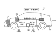
本発明の一実施形態による化学蓄熱装置100は、図1に示すように、エンジン120を有する自動車などの車両110に搭載されるように構成されている。また、化学蓄熱装置100は、車両110の通常走行時などの暖機完了後には、エンジン120から排出されて排気管130の内部を流通する高温の排ガスGを利用して蓄熱するように構成されている。また、車両110の冷間始動時や走行初期などの暖機完了前には、エンジン120から排出されて排気管130の内部を流通する低温の排ガスGに対して蓄熱した熱を供給する(放熱する)ように構成されている。これにより、化学蓄熱装置100の後方に配置された熱交換器140および触媒150に暖められた排ガスGが供給されるように構成されている。なお、エンジン120は、本発明の「内燃機関」の一例であり、排ガスGは、本発明の「熱交換流体」の一例である。また、高温の排ガスGは、本発明の「高温熱交換流体」の一例である。
As shown in FIG. 1, the chemical
図1に示す車両110の通常走行時などの暖機完了後には、エンジン120から排出された高温の排ガスGが排気管130bを流通する。そして、図5に示すように、導入口61から導入された高温の排ガスGが、熱交換流路Aにおいて、反応容器部11の外表面11dを流れる。この際、反応容器部11の外表面11dおよびフィン12を介して反応容器部11に高温の排ガスGからの熱が伝熱され、その結果、反応容器部11の蓄熱材収容部11aから水酸化カルシウムからなる蓄熱材8(蓄熱可能な蓄熱材8)に伝熱されている。しかしながら、弁4(図4参照)が閉鎖されている状態では、脱水反応によって生じた水蒸気が、配管部31および8つの蓄熱材収容部11aからなる空間に飽和しているため、これ以上、蓄熱材8において脱水反応(蓄熱)は行われない。
After completion of warming-up, such as during normal running of the
図2に示す車両110の冷間始動時や走行初期などの暖機完了前には、エンジン120から排出された低温の排ガスGが排気管130bを流通する。そして、図5に示すように、導入口61から導入された低温の排ガスGが、熱交換流路Aにおいて、反応容器部11の外表面11dを流れる。この際、低温の排ガスGにより、反応容器部11の外表面11dおよびフィン12を介して反応容器部11の蓄熱材収容部11aが冷やされる(蓄熱材収容部11aから熱が奪われる)。しかしながら、弁4(図4参照)が閉鎖されている状態では、水蒸気が存在しないため、蓄熱材8において水和反応(放熱)は行われない。なお、配管部31および8つの蓄熱材収容部11aからなる空間は、水蒸気が存在しない分、減圧されている。
Before completion of warming up such as cold start and running
また、本実施形態では、車両110の通常走行時などの暖機完了後には、エンジン120から排出された高温の排ガスGが排気管130bを流通する。そして、導入口61から導入された高温の排ガスGが、熱交換流路Aにおいて、反応容器部11の外表面11dを流れることにより、化学蓄熱装置100において蓄熱が行われる。一方、車両110の冷間始動時や走行初期などの暖機完了前には、エンジン120から排出された低温の排ガスGが排気管130bを流通する。そして、導入口61から導入された低温の排ガスGが、熱交換流路Aにおいて、反応容器部11の外表面11dを流れることにより、化学蓄熱装置100において放熱が行われて低温の排ガスGが温められる。この結果、熱交換器140を介してヒータコア160およびバッテリ170が加熱される。これにより、暖機完了後において高温の排ガスGから熱を効率よく、かつ、迅速に吸収することができるとともに、暖機完了前に吸収した熱を効率よく、かつ、迅速に放出して、車両110のヒータコア160およびバッテリ170を温めることができる。この結果、車両110の排ガスGの熱を有効に活用して、車両110における電力消費を低減することができる。
Further, in the present embodiment, after completion of warming-up, such as during normal running of the
Claims (6)
熱交換流体が前記反応容器の外表面に沿って流れるように設けられた熱交換流路と、を備え、
前記熱交換流体の流動力により、前記反応容器が回転されて前記蓄熱材の撹拌が行われるように構成されており、
前記反応容器の外表面には、伝熱を促進するためのフィンが設けられており、
前記熱交換流路では、前記熱交換流体が前記フィンに接触しながら流れるように構成されており、
前記反応容器は、複数の反応容器部に分割されており、
前記複数の反応容器部の各々の外表面には、前記フィンが設けられているとともに、隣接する前記反応容器部同士が前記フィンにより連結されている、化学蓄熱装置。 A reaction vessel containing a heat storage material;
A heat exchange channel provided so that a heat exchange fluid flows along the outer surface of the reaction vessel,
The reaction vessel is rotated by the flow force of the heat exchange fluid, and the heat storage material is agitated .
Fins for promoting heat transfer are provided on the outer surface of the reaction vessel,
In the heat exchange flow path, the heat exchange fluid is configured to flow while in contact with the fins,
The reaction vessel is divided into a plurality of reaction vessel parts,
A chemical heat storage device in which the fins are provided on the outer surface of each of the plurality of reaction container parts, and the adjacent reaction container parts are connected to each other by the fins .
蓄熱時に、前記高温熱交換流体の流動力により、前記反応容器が回転されて前記蓄熱材の撹拌が行われるように構成されている、請求項1に記載の化学蓄熱装置。 The heat exchange fluid is a high temperature heat exchange fluid;
The chemical heat storage device according to claim 1, wherein the reaction container is rotated and the heat storage material is agitated by the fluid force of the high-temperature heat exchange fluid during heat storage .
前記蒸発凝縮器は、前記反応容器とともに移動するように構成されている、請求項1または2に記載の化学蓄熱装置。 It further comprises an evaporative condenser that collects water vapor released from the heat storage material by dehydration during heat storage and supplies water vapor that hydrates with the heat storage material during heat release to the heat storage material,
The evaporative condenser, the is configured to move together with the reaction vessel, the chemical heat storage device according to claim 1 or 2.
前記蒸気配管は、水和反応時に前記蒸発凝縮器からの液滴が飛散するのを抑制する折り返し構造を含む、請求項3に記載の化学蓄熱装置。 Further comprising a steam pipe connecting the evaporative condenser and the reaction vessel;
The chemical heat storage device according to claim 3 , wherein the steam pipe includes a folded structure that suppresses scattering of droplets from the evaporation condenser during a hydration reaction.
前記車両の内燃機関の暖機完了後に、高温の排ガスからなる高温熱交換流体が前記反応容器の外表面に沿って流れることにより前記蓄熱材による蓄熱が行われ、前記車両の内燃機関の暖機完了前に、前記蓄熱材に放熱させることにより前記車両の所定部分の加熱が行われるように構成されている、請求項1〜5のいずれか1項に記載の化学蓄熱装置。 The reaction vessel is installed in a vehicle having an internal combustion engine,
After completion of the warm-up of the internal combustion engine of the vehicle, the heat storage by the heat storage material is carried out by flowing the hot heat exchange fluid comprising from hot flue gas along the outer surface of the reaction vessel, the warm-up of the internal combustion engine of the vehicle The chemical heat storage device according to any one of claims 1 to 5 , wherein a predetermined portion of the vehicle is heated by radiating heat to the heat storage material before completion.
Priority Applications (5)
| Application Number | Priority Date | Filing Date | Title |
|---|---|---|---|
| JP2013146397A JP6056691B2 (en) | 2013-07-12 | 2013-07-12 | Chemical heat storage device |
| EP14822535.2A EP3006883B1 (en) | 2013-07-12 | 2014-06-19 | Chemical thermal energy storage device |
| PCT/JP2014/066244 WO2015005085A1 (en) | 2013-07-12 | 2014-06-19 | Chemical thermal energy storage device |
| US14/903,895 US9869518B2 (en) | 2013-07-12 | 2014-06-19 | Chemical heat storage device |
| CN201480039007.2A CN105378419B (en) | 2013-07-12 | 2014-06-19 | Chemical heat storage device |
Applications Claiming Priority (1)
| Application Number | Priority Date | Filing Date | Title |
|---|---|---|---|
| JP2013146397A JP6056691B2 (en) | 2013-07-12 | 2013-07-12 | Chemical heat storage device |
Publications (3)
| Publication Number | Publication Date |
|---|---|
| JP2015017780A JP2015017780A (en) | 2015-01-29 |
| JP2015017780A5 true JP2015017780A5 (en) | 2016-01-14 |
| JP6056691B2 JP6056691B2 (en) | 2017-01-11 |
Family
ID=52279771
Family Applications (1)
| Application Number | Title | Priority Date | Filing Date |
|---|---|---|---|
| JP2013146397A Expired - Fee Related JP6056691B2 (en) | 2013-07-12 | 2013-07-12 | Chemical heat storage device |
Country Status (5)
| Country | Link |
|---|---|
| US (1) | US9869518B2 (en) |
| EP (1) | EP3006883B1 (en) |
| JP (1) | JP6056691B2 (en) |
| CN (1) | CN105378419B (en) |
| WO (1) | WO2015005085A1 (en) |
Families Citing this family (8)
| Publication number | Priority date | Publication date | Assignee | Title |
|---|---|---|---|---|
| CN105587380B (en) * | 2016-01-06 | 2018-06-26 | 周飞燕 | Exhaust gas processing device |
| CN105649728B (en) * | 2016-01-06 | 2017-12-01 | 嵊州北航投星空众创科技有限公司 | Durable type ternary catalyzing unit |
| CN106091778B (en) * | 2016-07-22 | 2017-09-29 | 金陵科技学院 | One kind rotation phase-change heat-exchanger and method of work |
| JP6868393B2 (en) * | 2016-12-28 | 2021-05-12 | 日本ペイントホールディングス株式会社 | Storage and heat dissipation device |
| CN108020107B (en) * | 2017-11-30 | 2019-06-04 | 上海理工大学 | A kind of rotary phase change heat accumulator and its application |
| CN109443066B (en) * | 2018-12-17 | 2024-02-02 | 思安新能源股份有限公司 | Output is stable solid heat storage system |
| JP2021110270A (en) * | 2020-01-08 | 2021-08-02 | 本田技研工業株式会社 | Installation structure of heat accumulator for vehicle |
| EP3882554A1 (en) | 2020-03-19 | 2021-09-22 | Nederlandse Organisatie voor toegepast- natuurwetenschappelijk Onderzoek TNO | Internal configuration for redox-based heat storage systems |
Family Cites Families (21)
| Publication number | Priority date | Publication date | Assignee | Title |
|---|---|---|---|---|
| US3253400A (en) * | 1961-08-07 | 1966-05-31 | Union Oil Co | Exhaust treatment apparatus and method |
| US3481144A (en) * | 1967-02-27 | 1969-12-02 | Jacque C Morrell | Apparatus and process for treatment of exhaust gases from internal combustion engines and controls for the same |
| US3563710A (en) * | 1968-02-16 | 1971-02-16 | Monsanto Co | Polymerization apparatus |
| JPS4844432B1 (en) * | 1969-02-18 | 1973-12-25 | ||
| JPS5543330A (en) * | 1978-09-20 | 1980-03-27 | Mitsubishi Electric Corp | Heat accumulator |
| JPS5560178A (en) * | 1978-10-27 | 1980-05-07 | Takeuchi Yutaka | Device for cooling viscous liquid |
| DE2931942A1 (en) * | 1979-08-07 | 1981-02-26 | Colt Int Gmbh | Rotary regenerative heat exchanger - has rotor with circular disc surfaces parallel to flow directions of media |
| JPS5832279U (en) * | 1981-08-24 | 1983-03-02 | 株式会社クボタ | Latent heat storage device |
| JPS5929987A (en) * | 1982-08-10 | 1984-02-17 | Yaskawa Electric Mfg Co Ltd | Heat exchanger |
| FR2571838B1 (en) * | 1984-10-12 | 1989-06-23 | Nishimura Jinichi | HEAT EXCHANGER STRUCTURE COMPRISING A ROTATING DRUM PROVIDED WITH FINS |
| JPS61294113A (en) | 1985-06-24 | 1986-12-24 | Toyota Motor Corp | Heat accumulating device |
| JPH0696114B2 (en) | 1989-09-18 | 1994-11-30 | 工業技術院長 | Method and apparatus for producing inorganic powder by hydrothermal synthesis |
| JPH05248728A (en) * | 1992-03-06 | 1993-09-24 | Hitachi Ltd | Chemically heat-accumulating type heat pump |
| KR100455839B1 (en) | 1999-11-26 | 2004-11-06 | 제이에프이 엔지니어링 가부시키가이샤 | Hydrate thermal storage medium and method for producing thereof, thermal storage apparatus using hydrate thermal storage medium, and hydrate cold thermal transportation medium |
| JP2001317887A (en) * | 2000-05-10 | 2001-11-16 | Central Res Inst Of Electric Power Ind | Thermal storage capsule |
| JP2010216772A (en) * | 2009-03-18 | 2010-09-30 | Toyota Central R&D Labs Inc | Chemical heat storage reactor and chemical heat storage system |
| CN101644548A (en) * | 2009-08-13 | 2010-02-10 | 哈尔滨工程大学 | High-temperature chemical heat storage element and heat storage device based on high-temperature chemical heat storage element |
| IT1399798B1 (en) | 2010-05-04 | 2013-05-03 | Fontana | LOCKING / UNLOCKING SYSTEM OF STACKABLE ELEMENTS. |
| JP5724302B2 (en) * | 2010-11-04 | 2015-05-27 | アイシン精機株式会社 | Chemical heat storage device and chemical heat storage device |
| JP2012211713A (en) * | 2011-03-30 | 2012-11-01 | Toyota Central R&D Labs Inc | Chemical heat storage reactor, and chemical heat storage system |
| CN102330994A (en) * | 2011-09-08 | 2012-01-25 | 林杰 | Rotary heat accumulating type heat exchanger |
-
2013
- 2013-07-12 JP JP2013146397A patent/JP6056691B2/en not_active Expired - Fee Related
-
2014
- 2014-06-19 US US14/903,895 patent/US9869518B2/en active Active
- 2014-06-19 EP EP14822535.2A patent/EP3006883B1/en not_active Not-in-force
- 2014-06-19 WO PCT/JP2014/066244 patent/WO2015005085A1/en active Application Filing
- 2014-06-19 CN CN201480039007.2A patent/CN105378419B/en not_active Expired - Fee Related
Similar Documents
| Publication | Publication Date | Title |
|---|---|---|
| JP2015017780A5 (en) | ||
| WO2011102323A1 (en) | Exhaust heat recovery device | |
| JP6056691B2 (en) | Chemical heat storage device | |
| JP2008290636A (en) | Hybrid car | |
| JP2010053830A (en) | Vehicle warming-up system | |
| JP2009185773A (en) | Exhaust heat utilization device | |
| JP5786132B2 (en) | Electric car | |
| JP6553521B2 (en) | Exhaust gas circulation system | |
| JP6183935B1 (en) | Engine exhaust heat recovery method | |
| JP2010265812A (en) | Heat exchanger | |
| JP2011094564A (en) | Accumulator for engine warm-up, and engine warm-up system having the same | |
| JP5801593B2 (en) | Thermal storage heating system for vehicles | |
| JP2010281236A (en) | Warm-up device of internal combustion engine | |
| JP6284412B2 (en) | Thermal storage fuel heater | |
| JP5755963B2 (en) | Thermal storage water heater | |
| JP4550077B2 (en) | Heat source machine | |
| JP6658303B2 (en) | Heat storage system and heat storage method for vehicle | |
| JP6201834B2 (en) | Heat storage device | |
| JP5749999B2 (en) | Heat storage device | |
| JP2010127121A (en) | Heat storage device and internal combustion engine | |
| JP5789972B2 (en) | Engine warm-up device | |
| JP2020128851A (en) | Heat storage body, heat storage device, and heat storage heating device | |
| JP4001025B2 (en) | Water heater | |
| JP2020128840A (en) | Heat storage piping compact, heat storage piping group body, heat storage piping body and heat storage heating device | |
| JP6171699B2 (en) | Exhaust heat recovery unit |