JP5801593B2 - Thermal storage heating system for vehicles - Google Patents
Thermal storage heating system for vehicles Download PDFInfo
- Publication number
- JP5801593B2 JP5801593B2 JP2011092348A JP2011092348A JP5801593B2 JP 5801593 B2 JP5801593 B2 JP 5801593B2 JP 2011092348 A JP2011092348 A JP 2011092348A JP 2011092348 A JP2011092348 A JP 2011092348A JP 5801593 B2 JP5801593 B2 JP 5801593B2
- Authority
- JP
- Japan
- Prior art keywords
- heat
- heat medium
- storage tank
- flow path
- engine
- Prior art date
- Legal status (The legal status is an assumption and is not a legal conclusion. Google has not performed a legal analysis and makes no representation as to the accuracy of the status listed.)
- Expired - Fee Related
Links
Images


Landscapes
- Exhaust-Gas Circulating Devices (AREA)
- Air-Conditioning For Vehicles (AREA)
Description
本発明は、車両の機器類の排熱を利用して冷間始動時に車両に装備した機器類の暖機や流体類の昇温を促進できるようにする、車両用蓄熱式加温装置に関するものである。 The present invention relates to a regenerative heating apparatus for a vehicle that makes it possible to promote warm-up of equipment mounted on the vehicle at the time of cold start and temperature rise of fluids using exhaust heat of the vehicle equipment. It is.
自動車(単に、車両とも言う)において、冷間始動時には、エンジンを始めとする各機器自体と共に、各機器の作動に欠かせない冷却水や潤滑オイル等の流体類も低温状態になっている。これらの機器類や流体類が低温の場合、機器が適正に作動しない不具合や、機器が作動する際に大きなフリクションを招く不具合が発生する。そこで、機器類の暖機や流体類の昇温を速やかに行なえるようにすることが要望される。特に、車両に装備した機器類の排熱を利用して各機器の暖機や流体類の昇温を促進できるようにすれば、エネルギ効率がよい。 In an automobile (also simply referred to as a vehicle), at the time of cold start, fluids such as cooling water and lubricating oil, which are indispensable for the operation of each device, are in a low temperature state together with each device such as an engine. When these devices and fluids are at a low temperature, there are problems that the device does not operate properly and that causes large friction when the device operates. Therefore, it is desired to be able to quickly warm up the devices and heat up the fluids. In particular, energy efficiency is good if the exhaust heat of the devices installed in the vehicle is used to promote the warm-up of each device and the temperature rise of the fluids.
このような技術としては、例えば、特許文献1には、エンジンの暖機をより速やかに行うことを目的としたエンジンの冷却装置が開示されている。この装置は、冷却媒体を保温しながら貯留するように構成された蓄熱タンクを備え、蓄熱タンク内に貯留された暖かい冷却媒体は、エンジン始動の際に、シリンダブロックに導入される。このように導入された暖かい冷却媒体がエンジンを加温するので、エンジン始動の際にシリンダブロックが暖機される(プレヒート)。
As such a technique, for example,
さらに、その後、暖機運転終了前に、シリンダブロックから蓄熱タンクに冷却媒体が排出される。これにより、シリンダブロックから冷却媒体への熱の逃げがなくなり、暖機運転が迅速に行われる。
なお、蓄熱タンクに蓄えられる暖かい冷却媒体は、前回のエンジン停止後しばらく経過した状態において、シリンダブロックから蓄熱タンクに排出されたものである。
Furthermore, after that, before the warm-up operation ends, the cooling medium is discharged from the cylinder block to the heat storage tank. Thereby, there is no escape of heat from the cylinder block to the cooling medium, and the warm-up operation is performed quickly.
The warm cooling medium stored in the heat storage tank is discharged from the cylinder block to the heat storage tank after a while has passed since the previous engine stop.
また、自動車に関するものでもなく、機器類の暖機に関するものでもないが、特許文献2には、発電機を駆動して発電を行なうと共に機関で生じた熱を利用して高温熱水を生成して蓄熱槽に蓄えて熱水又は蒸気を外部へ供給するコジェネレーション用ディーゼルエンジンに関し、EGRガスの熱を利用して蓄熱槽に蓄えた熱水の温度を高温に保持する技術が開示されている。 Further, although it is not related to automobiles and not related to warm-up of equipment, Patent Document 2 discloses that electric power is generated by driving a generator and high-temperature hot water is generated using heat generated in an engine. In relation to a diesel engine for cogeneration that is stored in a heat storage tank and supplies hot water or steam to the outside, a technique for maintaining the temperature of the hot water stored in the heat storage tank at a high temperature using the heat of EGR gas is disclosed. .
この技術では、外部供給の熱水又は蒸気を生成するために外部からの冷水を、EGR管路に設けられたEGRガス熱交換器(EGRクーラ)に導入してEGRガスを冷却すると共に導入した冷水を温め、このやや温まった水をさらにエンジン冷却水熱交換器に導入してエンジン冷却水を冷却すると共に導入したやや温まった水をさらに温め、温められた温水をエンジンの排気を導入した加熱器でさらに加熱し高温にして蓄熱槽に蓄えて、蓄熱槽から外部へ熱水又は蒸気として供給する。 In this technology, in order to generate externally supplied hot water or steam, cold water from the outside is introduced into an EGR gas heat exchanger (EGR cooler) provided in the EGR pipe to cool and introduce the EGR gas. Warm the cold water, introduce this slightly warm water into the engine cooling water heat exchanger to cool the engine cooling water, further warm the slightly warm water introduced, and heat the warm water to introduce the engine exhaust It is further heated in a vessel, heated to a high temperature, stored in a heat storage tank, and supplied from the heat storage tank as hot water or steam.
出力電力が小さいが熱水使用量が多い状況下では蓄熱槽の熱水温度が低下するが、この場合に、EGR弁を開いてEGRガス熱交換器へのEGRガス流量を増大させれば、熱水温度の低下を抑えることができる。 In the situation where the output power is small but the amount of hot water used is large, the hot water temperature of the heat storage tank decreases, but in this case, if the EGR valve is opened and the EGR gas flow rate to the EGR gas heat exchanger is increased, A decrease in hot water temperature can be suppressed.
しかしながら、特許文献1に記載の技術では、蓄熱タンクに蓄えられる暖かい冷却媒体は、エンジンのシリンダブロックから排出されたものであり、冷却水を十分に加熱できない場合が考えられる。この点、特許文献2に記載された、EGRガスの熱を利用して熱水の温度を高温に保持する技術を適用すれば、冷却水を十分に加熱することが可能になる。
しかし、特許文献2の技術では、EGRクーラ等で加熱して蓄熱槽に蓄える熱水に用いる水は、エンジンの冷却水とは別のものであり、冷却水とは別の流通系統を一方向に流通して蓄熱槽から外部に供給される。車両の機器類の暖機や流体類の昇温を行なうには、冷却水等の冷媒流体(熱媒流体)を閉じた回路で用いるため、特許文献2の技術をそのまま適用することはできない。
However, in the technique described in
However, in the technique of Patent Document 2, the water used for the hot water heated by the EGR cooler or the like and stored in the heat storage tank is different from the engine cooling water, and the distribution system different from the cooling water is unidirectional. And is supplied to the outside from the heat storage tank. In order to warm up the equipment of the vehicle and to raise the temperature of the fluids, since the refrigerant fluid (heat medium fluid) such as cooling water is used in a closed circuit, the technique of Patent Document 2 cannot be applied as it is.
本発明は、かかる課題に鑑み創案されたもので、シンプルな構成で、車両に装備した機器類の排熱を利用して各機器の暖気や流体類の昇温を効率よく促進できるようにした、車両用蓄熱式加温装置を提供することを目的とする。 The present invention was devised in view of such a problem, and has a simple configuration and can efficiently promote the warming of each device and the temperature rise of fluids using the exhaust heat of the devices mounted on the vehicle. An object of the present invention is to provide a vehicle heat storage type heating device.
上記の目的を達成するために、本発明の車両用蓄熱式加温装置は、車両に装備され熱媒体が循環する熱媒体回路と、前記熱媒体回路に介装され前記熱媒体を放熱する放熱手段と、前記熱媒体回路に介装され前記車両のエンジンの排気と前記熱媒体との間で熱交換を行なう熱交換手段と、前記熱媒体回路に介装され前記熱媒体を前記熱媒体回路内で循環駆動する第1の熱媒体駆動手段と、前記熱媒体回路の前記熱交換手段の下流部と前記放熱手段の上流部との間の回路部分を迂回するように接続された第1のバイパス熱媒体回路と、前記第1のバイパス熱媒体回路に介装され、前記熱交換手段により加熱された前記熱媒体を蓄える容量可変式の蓄熱タンクと、放熱した前記熱媒体を一時貯留する容量可変式の一時貯留タンクと、上流端を前記蓄熱タンクに下流端を前記一時貯留タンクにそれぞれ接続された第2のバイパス熱媒体回路と、前記第2のバイパス熱媒体回路に介装され流通する前記熱媒体により前記車両の機器類又は流体類を加温する加温手段と、前記蓄熱タンク内の前記熱媒体を前記加温手段に供給すると共に前記加温手段に残存していた前記熱媒体を前記一時貯留タンク内に送出するように前記第2のバイパス熱媒体回路で前記熱媒体を循環駆動する第2の熱媒体駆動手段と、前記熱交換手段により加熱された前記熱媒体を前記蓄熱タンクに供給する流路を開通させる第1流路切替手段と、前記一時貯留タンク内に一時貯留された前記熱媒体を前記熱媒体回路に戻す流路を開通させる第2流路切替手段と、をそなえていることを特徴としている。 In order to achieve the above object, a heat storage type heating apparatus for a vehicle according to the present invention includes a heat medium circuit that is provided in a vehicle and in which a heat medium circulates, and that dissipates heat from the heat medium that is interposed in the heat medium circuit. Means, heat exchange means interposed in the heat medium circuit for exchanging heat between the exhaust of the vehicle engine and the heat medium, and the heat medium circuit interposed in the heat medium circuit. A first heat medium driving means that circulates within the first heat medium driving means, and a first heat medium driving means that is connected to bypass a circuit portion between the downstream portion of the heat exchange means and the upstream portion of the heat dissipation means of the heat medium circuit. A bypass heat medium circuit, a variable capacity heat storage tank that is interposed in the first bypass heat medium circuit and stores the heat medium heated by the heat exchange means, and a capacity for temporarily storing the radiated heat medium Variable storage tank and upstream end A second bypass heat medium circuit having a downstream end connected to the temporary storage tank and a second bypass heat medium circuit connected to the temporary storage tank, and the vehicle equipment or fluid by the heat medium interposed and circulated in the second bypass heat medium circuit. Heating means for heating, and supplying the heat medium in the heat storage tank to the heating means and sending the heat medium remaining in the heating means into the temporary storage tank. Second heat medium driving means for circulatingly driving the heat medium in two bypass heat medium circuits, and a first flow path for opening a flow path for supplying the heat medium heated by the heat exchange means to the heat storage tank It is characterized by comprising switching means and second flow path switching means for opening a flow path for returning the heat medium temporarily stored in the temporary storage tank to the heat medium circuit.
前記蓄熱タンク及び前記一時貯留タンクは、1つの容器内を可動仕切壁で区画された一体型タンクであることが好ましい。
前記熱媒体は前記エンジンの冷却水であると共に、前記放熱手段は前記冷却水を放熱するラジエータであって、前記ラジエータには、前記冷却水によって前記エンジンを冷却する冷却水循環回路が接続され、前記熱媒体回路は、前記冷却水循環回路の途中から分岐して前記熱交換手段に向かい更に前記ラジエータに戻るように接続されていることが好ましい。
It is preferable that the heat storage tank and the temporary storage tank are integrated tanks in which one container is partitioned by a movable partition wall.
The heat medium is cooling water for the engine, and the heat dissipating means is a radiator that radiates the cooling water, and the radiator is connected to a cooling water circulation circuit that cools the engine with the cooling water, It is preferable that the heat medium circuit is connected so as to branch from the middle of the cooling water circulation circuit toward the heat exchanging means and further return to the radiator.
前記熱交換手段は、前記エンジンに装備されたEGR流路に介装されてEGRガスを冷却するEGRクーラであることが好ましい。
前記熱交換手段は、前記エンジンの処理済の排気が流通する排気管に装備されることが好ましい。
前記加温手段により加温される前記車両の機器類又は流体類は、前記エンジンのエンジンオイル、前記エンジンに接続されたトランスミッションのトランスミッションオイル、前記トランスミッションからの回転力を駆動輪に配分するデファレンシャルのデファレンシャルオイル、及び、前記車両の空調用ヒータの少なくともいずれかであることが好ましい。
Preferably, the heat exchange means is an EGR cooler that is interposed in an EGR flow path equipped in the engine and cools EGR gas.
It is preferable that the heat exchanging means is provided in an exhaust pipe through which exhausted exhaust from the engine flows.
The vehicle equipment or fluid heated by the heating means includes engine oil of the engine, transmission oil of a transmission connected to the engine, and a differential that distributes rotational force from the transmission to drive wheels. Preferably, the oil is at least one of a differential oil and an air conditioning heater for the vehicle.
前記第2の熱媒体駆動手段は、前記蓄熱タンクの入出口近傍に設けられた電動ポンプであって、前記第1及び第2流路切替手段は、何れも電磁バルブであって、前記熱媒体回路内における前記熱媒体の温度を検出する第1の温度検出手段と、前記蓄熱タンク内における前記熱媒体の温度を検出する第2の温度検出手段と、前記第1及び第2の温度検出手段からの検出情報に基づいて、前記第2の熱媒体駆動手段並びに前記第1及び第2流路切替手段を制御する制御手段を備え、前記制御手段は、前記エンジンの冷間始動を判定し、該冷間始動時には、前記第1流路切替手段を遮断し前記第2流路切替手段を開放すると共に、前記第2のバイパス熱媒体回路で前記熱媒体が前記循環駆動するように前記第2の熱媒体駆動手段を制御し、前記蓄熱タンク内における前記熱媒体の温度が前記熱媒体回路内における前記熱媒体の温度よりも低い低温状態であることを判定して、該低温状態のときには、前記第1流路切替手段を開放し前記第2流路切替手段を遮断すると共に、前記熱交換手段により加熱された前記熱媒体の前記蓄熱タンクへの供給を許容する或いは前記蓄熱タンクへの供給を加勢するように前記第2の熱媒体駆動手段を制御することが好ましい。 The second heat medium driving means is an electric pump provided near an inlet / outlet of the heat storage tank, and the first and second flow path switching means are both electromagnetic valves, and the heat medium A first temperature detecting means for detecting the temperature of the heat medium in the circuit; a second temperature detecting means for detecting the temperature of the heat medium in the heat storage tank; and the first and second temperature detecting means. Control means for controlling the second heat medium driving means and the first and second flow path switching means based on the detection information from the control means, the control means determines a cold start of the engine, At the time of the cold start, the first flow path switching means is shut off and the second flow path switching means is opened, and the second bypass heat medium circuit causes the heat medium to be circulated and driven. Controlling the heat medium drive means of the heat storage It is determined that the temperature of the heat medium in the tank is a low temperature state lower than the temperature of the heat medium in the heat medium circuit, and in the low temperature state, the first flow path switching means is opened and the The second heat medium is configured to block the second flow path switching unit and permit the supply of the heat medium heated by the heat exchange unit to the heat storage tank or to energize the supply to the heat storage tank. It is preferable to control the driving means.
本発明の車両用蓄熱式加温装置によれば、熱交換手段により、エンジンの排気と熱媒体との間で熱交換を行なうことにより、排気を冷却し熱媒体を加熱して、加熱された熱媒体を第1のバイパス熱媒体回路にある容量可変式の蓄熱タンクに供給し蓄える。この蓄熱タンク内に蓄えられた加熱された熱媒体は、例えば冷間始動時に、第2の熱媒体駆動手段によって、第2のバイパス熱媒体回路に介装された加温手段に供給すると共に、加温手段に残存していた熱媒体を一時貯留タンク内に送出することにより、熱媒体により車両の機器類又は流体類を加温する。したがって、排気の熱を利用して車両の機器類又は流体類を効率的に加温することができる。また、蓄熱タンクや一時貯留タンクは容量可変式なので、各タンク内への空気の浸入を防止するように構成でき保温効率がよい。 According to the vehicle heat storage type heating device of the present invention, heat is exchanged between the exhaust of the engine and the heat medium by the heat exchange means, thereby cooling the exhaust and heating the heat medium. The heat medium is supplied to and stored in a variable capacity heat storage tank in the first bypass heat medium circuit. The heated heat medium stored in the heat storage tank is supplied to the heating means interposed in the second bypass heat medium circuit by the second heat medium driving means at the time of cold start, for example, By sending the heat medium remaining in the heating means into the temporary storage tank, the vehicle equipment or fluid is heated by the heat medium. Therefore, it is possible to efficiently heat the equipment or fluid of the vehicle using the heat of the exhaust. In addition, since the heat storage tank and the temporary storage tank are variable in capacity, the heat storage tank and the temporary storage tank can be configured to prevent the ingress of air into each tank, and the heat retention efficiency is good.
蓄熱タンク及び一時貯留タンクを、1つの容器内を可動仕切壁で区画された一体型タンクとすれば、可動仕切壁を通じて蓄熱タンク及び一時貯留タンクの各容積を効率よく変更でき、また、コンパクトに構成できるため車載性も良い。
熱媒体としてエンジンの冷却水を適用すれば、冷却水のみを用いて、エンジンの冷却、排気の冷却、及び車両の機器類又は流体類の加温を実施することができ、装置をシンプルに効率よく構成することができる。
If the heat storage tank and the temporary storage tank are integrated into one container, the volume of the heat storage tank and the temporary storage tank can be changed efficiently through the movable partition wall. Since it can be configured, it is easy to mount.
If engine cooling water is used as the heat medium, the cooling of the engine, the exhaust, and the heating of vehicle equipment or fluids can be performed using only the cooling water, making the device simple and efficient. Can be configured well.
熱交換手段としてEGRクーラを適用すれば、温度の高い排気(EGRガス)を用いて、熱媒体の加熱を促進することができ、車両の機器類又は流体類の加温を確実に行なうことができる。
もちろん、熱交換手段を処理済の排気が流通する排気管に装備しても、車両の機器類又は流体類の加温を行なうことができ、且つ、大気に排出される排気の温度を下げることになり、走行する道路周りの温度環境の悪化を防止できる。
If an EGR cooler is applied as a heat exchange means, heating of the heat medium can be promoted by using high-temperature exhaust gas (EGR gas), and the vehicle equipment or fluids can be reliably heated. it can.
Of course, even if the heat exchanging means is installed in the exhaust pipe through which the treated exhaust flows, the vehicle equipment or fluid can be heated and the temperature of the exhaust exhausted to the atmosphere can be lowered. Therefore, it is possible to prevent deterioration of the temperature environment around the traveling road.
冷間始動時に、加温手段によりエンジンオイルやトランスミッションオイルやデファレンシャルのデファレンシャルオイルを加温すれば、機器が作動する際のフリクションを抑制でき、燃費の向上に寄与する。また、車両の空調用ヒータに適用すれば、速やかに暖房を開始することができる。
また、制御手段によって、熱媒体回路内における熱媒体の温度及び蓄熱タンク内における熱媒体の温度に基づいて、熱媒体の流動を制御すれば、加熱された熱媒体の蓄熱タンクへの供給や、蓄熱タンク内に蓄えられた加熱された熱媒体により車両の機器類又は流体類の加温を自動で行なうことができる。
If the engine oil, transmission oil, or differential differential oil is warmed by the warming means during cold start, friction during operation of the device can be suppressed, which contributes to improved fuel consumption. Moreover, if it applies to the heater for a vehicle air conditioning, heating can be started rapidly.
Further, if the flow of the heat medium is controlled by the control means based on the temperature of the heat medium in the heat medium circuit and the temperature of the heat medium in the heat storage tank, supply of the heated heat medium to the heat storage tank, Vehicle equipment or fluids can be automatically heated by the heated heat medium stored in the heat storage tank.
以下、図面により本発明の実施の形態について説明する。
なお、これらの実施形態では、車両としてトラックに代表される大型自動車を例示して説明するが、本発明の対象車両はこれに限るものではない。
<第1実施形態>
まず、第1実施形態にかかる車両用蓄熱式加温装置について、図1〜図4を参照して説明する。
Hereinafter, embodiments of the present invention will be described with reference to the drawings.
In these embodiments, a large vehicle represented by a truck will be described as an example of the vehicle. However, the target vehicle of the present invention is not limited to this.
<First Embodiment>
First, the thermal storage type heating device for vehicles concerning 1st Embodiment is demonstrated with reference to FIGS.
本実施形態では、エンジンの冷却水の循環系統に本発明を適用している。
図1に示すように、自動車(車両)に搭載されたエンジン(内燃機関)10には、ラジエータ(放熱手段)20を介装された冷却水回路22が導入されており、ラジエータ20に放熱され冷却された冷却水は、ポンプ23に駆動されて、流入路22aからエンジン10のシリンダブロック11に導入され、シリンダブロック11内のウォータジャケット11a内を流通してシリンダブロック11を冷却すると共に自身は加熱されながら、上方のシリンダヘッド12に上昇して、流路12aから流出路22bを経てラジエータ20へと流出する。流出路22bには、エンジン10の冷間時には閉鎖するサーモスタットバルブ24が設けられ、エンジン10の冷間時にはシリンダブロック11内での冷却水の流通(循環)は行なわれずエンジン10の速やかな暖機を促進するようになっている。なお、冷却水はリザーバタンク21内に備蓄されたものが適宜供給される。
In the present embodiment, the present invention is applied to an engine cooling water circulation system.
As shown in FIG. 1, an engine (internal combustion engine) 10 mounted on an automobile (vehicle) is provided with a cooling
また、エンジン10には、図1,図2,図3に示すように、排気通路14から吸気通路17にわたって設けられたEGR流路15と、EGR流路15に介装されたEGR弁16a及びEGRクーラ16とからなるEGR装置が設けられている。EGRクーラ16は、流通する排気(EGRガス)と流通する冷媒(熱媒体)との間で熱交換をして排気(EGRガス)を冷却する。したがって、EGRクーラ16を流通する冷媒は熱交換により加熱される。
Further, as shown in FIGS. 1, 2, and 3, the
本実施形態では、このEGRクーラ16で用いる冷媒に、エンジン10の冷却水が適用される構成になっている。
つまり、冷却水回路22の流入路22aから分岐してEGRクーラ16に向かう冷却水の流路30aと、EGRクーラ16からラジエータ20に戻る冷却水の流路30b,30cとからなる冷媒回路(熱媒体回路)30が設けられている。
In the present embodiment, the coolant for the
That is, a refrigerant circuit (heat) comprising a cooling
なお、冷却水回路22のポンプ23は、この冷媒回路30内の冷媒である冷却水も循環駆動させるので、本発明の第1の熱媒体駆動手段に相当する。
そして、かかる冷媒回路30のEGRクーラ16の直下流の流路30bには、バイパス流路(第1のバイパス熱媒体回路)31の一端が分岐するように接続され、バイパス流路31の他端は、EGRクーラ16の更に下流の流路(ラジエータ20の直上流の流路)30cに合流するように接続されている。このバイパス流路31には、電磁式の第1流路切替バルブ32と、電動ポンプ(第2の熱媒体駆動手段)33と、熱媒体貯留タンク40と、電磁式の第2流路切替バルブ35とが介装されている。
The
Then, one end of a bypass flow path (first bypass heat medium circuit) 31 is connected to the
つまり、バイパス流路31は、その一端側から流路31a,31b,31c,31dの各流路部分を備え、EGRクーラ16の直下流の流路30bに近い流路31aに流路切替バルブ32が介装され、これに続く流路31bにポンプ33が介装され、流路31bとEGRクーラ16の更に下流の流路30cに合流する流路31cとの間に熱媒体貯留タンク40が介装され、流路31cに第2流路切替バルブ35が介装される。
In other words, the
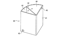
熱媒体貯留タンク40は、図4に示すように、扇形の横断面を有するタンク本体(タンクケース)41の内部が、扇形の要の箇所を中心に旋回する可動ベーン(可動仕切壁)42によって液密に仕切られて、熱媒体としての高温の冷却水を蓄える容量可変式の蓄熱タンク(保温タンク)43と、放熱後の熱媒体(低温の冷却水)を一時貯留する容量可変式の一時貯留タンク44との、2つのタンクに区画形成された一体型タンクである。
As shown in FIG. 4, the heat
ここでは、可動ベーン42は、蓄熱タンク43と一時貯留タンク44との圧力差に応じて従動で旋回する。
また、タンク本体41及び可動ベーン42は蓄熱タンク43の保温性を確保するために断熱性の高い材料及び構造を有して構成されている。
さらに、蓄熱タンク43及び一時貯留タンク44には、冷却水を入出させる開口部45,46がそれぞれ設けられ、それぞれ流路30b,30cの各端部が接続されている。
Here, the
Further, the
Furthermore, the
そして、このようなバイパス流路31に更に分岐するように、もう一つのバイパス流路(バイパス熱媒体回路)34が設けられている。
このバイパス流路34は、上流端を蓄熱タンク43に下流端を一時貯留タンク44にそれぞれ接続されており、その中間部には、車両に装備された機器類及び流体類を加温する加温装置(加温手段)51,52,53,54が介装されている。なお、バイパス流路34の上流部は、流路切替バルブ32に導入され、バイパス流路34の下流部は、流路切替バルブ35に導入されている。
Further, another bypass channel (bypass heat medium circuit) 34 is provided so as to further branch into the
The
加温装置51は、車室内を暖房する空調用ヒータであり、加温装置52はオイルパン13内のエンジンオイルを加温するエンジンオイルヒータであり、加温装置53はトランスミッションオイルを加温するトランスミッションオイルヒータであり、加温装置54は駆動輪のデファレンシャルオイル(デフオイル)を加温するデフオイルヒータである。
流路切替バルブ32は、EGRクーラ16から熱媒体貯留タンク40の蓄熱タンク43に向かう流路31aを開閉すると共に、蓄熱タンク43から、各加温装置51,52,53,54に向かうバイパス流路34を開閉する。特に、各加温装置51,52,53,54に加温要求があるときには、バイパス流路34を開放すると同時に流路31aを閉鎖し、上記加温要求がない通常時には、流路31aを開放すると同時にバイパス流路34を閉鎖する。なお、かかる連動開閉動作を達成できれば、流路31aの開閉とバイパス流路34の開閉とを別々のバルブで行なっても良い。
The warming
The flow
流路切替バルブ35は、一時貯留タンク44に連通する流路31cとバイパス流路34の下流端との間を連通状態とし、流路31cとEGRクーラ16の更に下流の流路(ラジエータ20の直上流の流路)30cとの間を遮断状態とするモードと、一時貯留タンク44に連通する流路31cとバイパス流路34の下流端との間を遮断状態とし、流路31cとEGRクーラ16の更に下流の流路(ラジエータ20の直上流の流路)30cとの間を連通状態とするモードとを切り換える。なお、かかる連動開閉動作を達成できれば、流路31cとバイパス流路34との開閉と、流路31cと30cとの開閉と、を別々のバルブで行なっても良い。
The flow
ポンプ33は、加温要求時には、蓄熱タンク43に貯留された加熱された冷却水(熱媒体)を蓄熱タンク43からバイパス流路34を経て各加温装置51,52,53,54に向かうように駆動する。このときには、各加温装置51,52,53,54に残存する冷えた冷却水(熱媒体)はバイパス流路34を経て一時貯留タンク44に送られる。また、ポンプ33は、加温要求がない時には、停止して、EGRクーラ16から熱媒体貯留タンク40の蓄熱タンク43に向かう冷却水の流れを許容するか、或いは、EGRクーラ16から熱媒体貯留タンク40の蓄熱タンク43に向かう冷却水の流れを加勢するように作動する。
When the heating is requested, the
このような流路切替バルブ32,35及びポンプ33の作動は、コントローラ61によって制御される。コントローラ61は、熱媒体回路30内における冷却水(熱媒体)の温度と、蓄熱タンク43内における冷却水(熱媒体)の温度とに基づいて、流路切替バルブ32,35及びポンプ33の作動を制御する。
なお、熱媒体回路30内における冷却水(熱媒体)の温度は、エンジンに付設された図示しない冷却水温度センサ(第1の温度検出手段)の検出情報(冷却水温度情報)をエンジンECU60から伝達されて取得し、蓄熱タンク43内における冷却水(熱媒体)の温度は、蓄熱タンク43に付設された温度センサ(第2の温度検出手段)62の検出情報(保温タンク温度情報)を伝達されて取得する。
The operations of the flow
The temperature of the cooling water (heat medium) in the
コントローラ61では、エンジン始動時に、冷却水温度Tcを予め設定された閾値Tc0と比較してエンジン10が冷間始動であるかを判定する。冷却水温度Tcが閾値Tc0未満なら冷間始動であると判定し、この冷間始動時には、加温要求があるものとし、流路切替バルブ32を、バイパス流路34を開放すると同時に流路31aを閉鎖する状態とし、流路切替バルブ35を、流路31cとバイパス流路34の下流端との間を連通状態とし流路31cと流路30cとの間を遮断状態とする。そして、ポンプ33を、蓄熱タンク43に貯留された加熱された冷却水(熱媒体)を蓄熱タンク43からバイパス流路34を経て各加温装置51,52,53,54に向かうように駆動する。
The
これにより、車室内を暖房する空調用ヒータ51、エンジンオイルを加温するエンジンオイルヒータ、トランスミッション4内のトランスミッションオイルを加温するトランスミッションオイルヒータ53、駆動輪のデファレンシャルオイル(デフオイル)を加温するデフオイルヒータ54がそれぞれ、蓄熱タンク43からの高温の冷却水で加温作動して、暖房又は暖機する。
Thus, the
また、コントローラ61では、エンジン等の暖機完了後に、保温タンク温度Twと冷却水温度Tcとを比較して、保温タンク温度Twが冷却水温度Tcよりも低い低温状態のときには、流路切替バルブ32を、流路31aを開放すると同時にバイパス流路34を閉鎖する状態とし、流路切替バルブ35を、流路31cとバイパス流路34の下流端との間を遮断状態とし流路31cと流路30cとの間を連通状態とする。また、ポンプ33を、EGRクーラ16から熱媒体貯留タンク40の蓄熱タンク43に向かう冷却水の流れを許容するか、或いは、EGRクーラ16から熱媒体貯留タンク40の蓄熱タンク43に向かう冷却水の流れを加勢するように作動させる。
Further, the
これにより、蓄熱タンク43内に高温の冷却水(熱媒体)が導入されると同時に、一時貯留タンク44内の冷たい冷却水(熱媒体)が、冷媒回路(熱媒体回路)30及び冷却水回路22に送られて各部の冷却に利用される。
本発明の第1実施形態にかかる車両用蓄熱式加温装置は、上述のように構成されているので、EGRクーラ16によって、エンジン10の排気と冷却水(熱媒体)との間で熱交換を行なうことにより、排気を冷却し冷却水を加熱して、加熱された冷却水を容量可変式の蓄熱タンク43に供給し蓄える。この蓄熱タンク43内に蓄えられた加熱された冷却水は、冷間始動時に、車室内を暖房する空調用ヒータ51、エンジンオイルを加温するエンジンオイルヒータ、トランスミッションオイルを加温するトランスミッションオイルヒータ53、駆動輪のデファレンシャルオイル(デフオイル)を加温するデフオイルヒータ54のそれぞれに送られて、各加温装置51〜54の冷たい冷却水と交換されるため、これらの機器類や流体類が高温の冷却水で速やかに加温される。
As a result, high-temperature cooling water (heat medium) is introduced into the
Since the vehicle heat storage type heating device according to the first embodiment of the present invention is configured as described above, heat exchange is performed between the exhaust of the
これにより、機器の暖機が早期に実施されて機器が作動する際のフリクションを抑制でき、燃費の向上に寄与する。また、車両の空調用ヒータ51にあっては、速やかに暖房を開始することができる。
蓄熱タンク43や一時貯留タンク44は容量可変式なので、各タンク43,44内への空気の浸入を防止するように構成でき保温効率がよい。
As a result, it is possible to suppress friction when the equipment is warmed up early and the equipment is operated, which contributes to an improvement in fuel consumption. Further, in the
Since the
また、蓄熱タンク43及び一時貯留タンク44を、1つの容器内を可動ベーン42で区画された一体型タンク40としているので、可動ベーン42を通じて蓄熱タンク43及び一時貯留タンク44の各容積を効率よく変更でき、また、コンパクトに構成できるため車載性も良い。
熱媒体としてエンジン10の冷却水を適用しているので、冷却水のみを用いて、エンジン10の冷却、排気(EGRガス)の冷却、及び車両の機器類又は流体類の加温を実施することができ、装置をシンプルに効率よく構成することができる。
In addition, since the
Since the cooling water of the
熱交換手段としてEGRクーラ16を適用しているので、温度の高い排気(EGRガス)を用いて、熱媒体の加熱を促進することができ、車両の機器類又は流体類の加温を確実に行なうことができる。また、EGRクーラ16はエンジン10の直近に位置するので、デフオイルヒータ54はプロペラシャフト5と駆動輪である後輪7との間のデファレンシャル6は荷室3の下部にやや離隔するものの、車体1の車室2下に熱交換手段の周りの多くの流路配管を配置できるので、配管も短くシンプルにできる(図2参照)。
Since the
<第2実施形態>
次に、本発明に関連する第2実施形態にかかる車両用蓄熱式加温装置について、図5を参照して説明する。
なお、図5において、第1実施形態(図1〜図4)と同様の部材や部位については同一符号を付与し、説明を省略する。
本実施形態では、排気と熱媒体との間で熱交換する熱交換器(熱交換手段)116を、排気処理部18の下流の処理済の排気が流通する排気管のマフラー部19に装備している。熱媒体及びその回路130(130a〜130d),131b,131c,134は、冷却水とは別系統に構成され、放熱手段にはコンデンサ25が適用され、第1の熱媒体駆動手段にはコンプレッサ26が適用されている。熱媒体としては、水,エタノール,CO2等の適宜のものを使用している。
Second Embodiment
Next, a vehicle heat storage type heating apparatus according to a second embodiment related to the present invention will be described with reference to FIG.
In FIG. 5, members and parts similar to those in the first embodiment (FIGS. 1 to 4) are assigned the same reference numerals and description thereof is omitted.
In the present embodiment, a heat exchanger (heat exchanging means) 116 for exchanging heat between the exhaust and the heat medium is installed in the
さらに、マフラー部19にエキスパンダ70を接続しており、マフラー部19を流通する排気が高温であれば、この高温の排気を推進剤としてエキスパンダ70が車両に装備された動力要素71を駆動するように構成されている。動力要素71としては、最も汎用性があるのは発電機であり、高温の排気エネルギを発電して電気エネルギとしてバッテリに蓄えることができる。また、動力要素71としては、車載の動力機器類であれば何れを適用しても良い。
Furthermore, if the
本発明に関連する第2実施形態としての車両用蓄熱式加温装置は、上述のように構成されているので、排気の熱エネルギが小さい場合には、排気の熱エネルギを熱交換器116で主に利用し蓄熱タンク43へ供給し、排気の熱エネルギが大きくなれば、排気の熱エネルギをエキスパンダ70と熱交換器116とで利用し、排気エネルギを効率よく回収することができる。
The vehicle heat storage type heating apparatus according to the second embodiment related to the present invention is configured as described above. Therefore, when the heat energy of the exhaust is small, the
<その他>
以上、本発明の実施の形態を説明したが、本発明は係る実施形態に限定されるものではなく、適宜変更して、又は、組み合わせて実施しうる。
<Others>
Although the embodiments of the present invention have been described above, the present invention is not limited to such embodiments, and can be appropriately modified or combined.
例えば、上記の実施形態では、タンク本体41内が可動ベーン42によって仕切られ、蓄熱タンク43と一時貯留タンク44とが備えられた一体型タンクの熱媒体貯留タンク40を適用したが、蓄熱タンク43と一時貯留タンク44とを、それぞれ個別の可変容量型タンクで構成しても良い。
また、一体型タンクの熱媒体貯留タンク40の場合も、扇形の横断面を有するものに限定されない。
For example, in the above embodiment, the heat
Further, the heat
さらに、第1実施形態において、熱交換器にEGRクーラを適用したが、熱交換器は排気熱を利用できればこれに限らず、第2実施形態のようにマフラー部19に熱交換器(熱交換手段)116を備えたものでも良い。
さらに、加温する車両の機器類又は流体類(加温対象)として、車室内を暖房する空調用ヒータ51、エンジンオイルを加温するエンジンオイルヒータ、トランスミッションオイルを加温するトランスミッションオイルヒータ53、駆動輪のデファレンシャルオイル(デフオイル)を加温するデフオイルヒータ54を例示したが、これに限らない。
Further, in the first embodiment, the EGR cooler is applied to the heat exchanger. However, the heat exchanger is not limited to this as long as the exhaust heat can be used, and the heat exchanger (heat exchange) is connected to the
Furthermore, as vehicle equipment or fluids to be heated (heating target), an
また、加温する条件も、冷間始動時に限らず、寒冷地や寒冷期には始動後であっても、機器類又は流体類の温度が低い状況下であれば、適用することが有効である。 In addition, the heating conditions are not limited to cold start, and it is effective to apply if the temperature of equipment or fluids is low even in cold districts or cold seasons even after startup. is there.
10 エンジン
11 シリンダブロック
12 シリンダヘッド
13 オイルパン
14 排気通路
15 EGR流路
16 EGRクーラ
16a EGR弁
17 吸気通路
18 排気処理部
19 排気管のマフラー部
20 ラジエータ(放熱手段)
21 リザーバタンク
22 冷却水回路
23 ポンプ(第1の熱媒体駆動手段)
30 冷媒回路(熱媒体回路)
31 バイパス流路(第1のバイパス熱媒体回路)
32 第1流路切替バルブ
33 電動ポンプ(第2の熱媒体駆動手段)
34 バイパス流路(第2のバイパス熱媒体回路)
35 第2流路切替バルブ
40 熱媒体貯留タンク
41 タンク本体(タンクケース)
42 可動ベーン(可動仕切壁)
43 容量可変式の蓄熱タンク(保温タンク)
44 容量可変式の一時貯留タンク
51,52,53,54 加温装置(加温手段)
60 エンジンECU(第2の温度検出手段)
61 コントローラ
62 温度センサ(第2の温度検出手段)
70 エキスパンダ
71 動力要素
DESCRIPTION OF
21
30 Refrigerant circuit (heat medium circuit)
31 Bypass flow path (first bypass heat medium circuit)
32 First flow
34 Bypass flow path (second bypass heat medium circuit)
35 Second flow
42 Movable vane (movable partition wall)
43 Variable capacity heat storage tank (heat insulation tank)
44 Temporary storage tank with
60 Engine ECU (second temperature detection means)
61
70
Claims (7)
前記熱媒体回路に介装され前記熱媒体を放熱する放熱手段と、
前記熱媒体回路に介装され前記車両のエンジンの排気と前記熱媒体との間で熱交換を行なう熱交換手段と、
前記熱媒体回路に介装され前記熱媒体を前記熱媒体回路内で循環駆動する第1の熱媒体駆動手段と、
前記熱媒体回路の前記熱交換手段の下流部と前記放熱手段の上流部との間の回路部分を迂回するように接続された第1のバイパス熱媒体回路と、
前記第1のバイパス熱媒体回路に介装され、前記熱交換手段により加熱された前記熱媒体を蓄える容量可変式の蓄熱タンクと、
放熱した前記熱媒体を一時貯留する容量可変式の一時貯留タンクと、
上流端を前記蓄熱タンクに下流端を前記一時貯留タンクにそれぞれ接続された第2のバイパス熱媒体回路と、
前記第2のバイパス熱媒体回路に介装され流通する前記熱媒体により前記車両の機器類又は流体類を加温する加温手段と、
前記蓄熱タンク内の前記熱媒体を前記加温手段に供給すると共に前記加温手段に残存していた前記熱媒体を前記一時貯留タンク内に送出するように前記第2のバイパス熱媒体回路で前記熱媒体を循環駆動する第2の熱媒体駆動手段と、
前記熱交換手段により加熱された前記熱媒体を前記蓄熱タンクに供給する流路を開通させる第1流路切替手段と、
前記一時貯留タンク内に一時貯留された前記熱媒体を前記熱媒体回路に戻す流路を開通させる第2流路切替手段と、をそなえている
ことを特徴とする、車両用蓄熱式加温装置。 A heat medium circuit installed in a vehicle and circulating a heat medium;
A heat dissipating means interposed in the heat medium circuit to dissipate the heat medium;
Heat exchanging means interposed in the heat medium circuit for exchanging heat between the exhaust of the engine of the vehicle and the heat medium;
First heat medium driving means interposed in the heat medium circuit and circulatingly driving the heat medium in the heat medium circuit;
A first bypass heat medium circuit connected to bypass a circuit portion between the downstream part of the heat exchange means and the upstream part of the heat dissipation means of the heat medium circuit;
A variable capacity heat storage tank that is interposed in the first bypass heat medium circuit and stores the heat medium heated by the heat exchange means;
A capacity-variable temporary storage tank that temporarily stores the heat medium that has dissipated heat;
A second bypass heat medium circuit having an upstream end connected to the heat storage tank and a downstream end connected to the temporary storage tank;
Heating means for heating equipment or fluids of the vehicle by the heat medium interposed and distributed in the second bypass heat medium circuit;
In the second bypass heat medium circuit, the heat medium in the heat storage tank is supplied to the heating means and the heat medium remaining in the heating means is sent into the temporary storage tank. Second heat medium driving means for circulatingly driving the heat medium;
First flow path switching means for opening a flow path for supplying the heat medium heated by the heat exchange means to the heat storage tank;
And a second flow path switching unit that opens a flow path for returning the heat medium temporarily stored in the temporary storage tank to the heat medium circuit. .
ことを特徴とする、請求項1記載の車両用蓄熱式加温装置。 The vehicle heat storage type heating apparatus according to claim 1, wherein the heat storage tank and the temporary storage tank are integrated tanks that are partitioned by a movable partition wall in one container.
前記ラジエータには、前記冷却水によって前記エンジンを冷却する冷却水循環回路が接続され、
前記熱媒体回路は、前記冷却水循環回路の途中から分岐して前記熱交換手段に向かい更に前記ラジエータに戻るように接続されている
ことを特徴とする、請求項1又は2記載の車両用蓄熱式加温装置。 The heat medium is cooling water for the engine, and the heat radiating means is a radiator that radiates heat from the cooling water,
A cooling water circulation circuit for cooling the engine with the cooling water is connected to the radiator,
3. The vehicle heat storage type according to claim 1, wherein the heat medium circuit is connected so as to diverge from the middle of the cooling water circulation circuit toward the heat exchange means and further return to the radiator. 4. Heating device.
ことを特徴とする、請求項1〜3の何れか1項に記載の車両用蓄熱式加温装置。 4. The vehicle-use vehicle according to claim 1, wherein the heat exchange means is an EGR cooler that is interposed in an EGR flow path equipped in the engine and cools EGR gas. 5. Thermal storage type heating device.
ことを特徴とする、請求項1〜3の何れか1項に記載の車両用蓄熱式加温装置。 The vehicle heat storage type heating apparatus according to any one of claims 1 to 3, wherein the heat exchange means is provided in an exhaust pipe through which exhausted exhaust from the engine flows.
ことを特徴とする、請求項1〜5の何れか1項に記載の車両用蓄熱式加温装置。 The vehicle equipment or fluid heated by the heating means includes engine oil of the engine, transmission oil of a transmission connected to the engine, and a differential that distributes rotational force from the transmission to drive wheels. The regenerative heating device for a vehicle according to any one of claims 1 to 5, which is at least one of differential oil and a heater for air conditioning of the vehicle.
前記熱媒体回路内における前記熱媒体の温度を検出する第1の温度検出手段と、
前記蓄熱タンク内における前記熱媒体の温度を検出する第2の温度検出手段と、
前記第1及び第2の温度検出手段からの検出情報に基づいて、前記第2の熱媒体駆動手段並びに前記第1及び第2流路切替手段を制御する制御手段を備え、
前記制御手段は、
前記エンジンの冷間始動を判定し、該冷間始動時には、前記第1流路切替手段を遮断し前記第2流路切替手段を開放すると共に、前記第2のバイパス熱媒体回路で前記熱媒体が前記循環駆動するように前記第2の熱媒体駆動手段を制御し、
前記蓄熱タンク内における前記熱媒体の温度が前記熱媒体回路内における前記熱媒体の温度よりも低い低温状態であることを判定して、該低温状態のときには、前記第1流路切替手段を開放し前記第2流路切替手段を遮断すると共に、前記熱交換手段により加熱された前記熱媒体の前記蓄熱タンクへの供給を許容する或いは前記蓄熱タンクへの供給を加勢するように前記第2の熱媒体駆動手段を制御する
ことを特徴とする、請求項1〜6の何れか1項に記載の車両用蓄熱式加温装置。 The second heat medium driving means is an electric pump provided in the vicinity of the inlet / outlet of the heat storage tank, and the first and second flow path switching means are both electromagnetic valves,
First temperature detecting means for detecting the temperature of the heat medium in the heat medium circuit;
Second temperature detecting means for detecting the temperature of the heat medium in the heat storage tank;
Control means for controlling the second heat medium driving means and the first and second flow path switching means based on detection information from the first and second temperature detection means,
The control means includes
The cold start of the engine is determined, and at the time of the cold start, the first flow path switching means is shut off and the second flow path switching means is opened, and the second bypass heat medium circuit Controlling the second heat medium driving means so as to circulate and drive,
It is determined that the temperature of the heat medium in the heat storage tank is a low temperature state lower than the temperature of the heat medium in the heat medium circuit, and when the temperature is low, the first flow path switching unit is opened. The second flow path switching means is shut off, and the second medium is allowed to allow supply of the heat medium heated by the heat exchange means to the heat storage tank or to energize supply to the heat storage tank. The heat storage warming device for a vehicle according to any one of claims 1 to 6, wherein the heat medium driving means is controlled .
Priority Applications (1)
| Application Number | Priority Date | Filing Date | Title |
|---|---|---|---|
| JP2011092348A JP5801593B2 (en) | 2011-04-18 | 2011-04-18 | Thermal storage heating system for vehicles |
Applications Claiming Priority (1)
| Application Number | Priority Date | Filing Date | Title |
|---|---|---|---|
| JP2011092348A JP5801593B2 (en) | 2011-04-18 | 2011-04-18 | Thermal storage heating system for vehicles |
Publications (2)
| Publication Number | Publication Date |
|---|---|
| JP2012225223A JP2012225223A (en) | 2012-11-15 |
| JP5801593B2 true JP5801593B2 (en) | 2015-10-28 |
Family
ID=47275662
Family Applications (1)
| Application Number | Title | Priority Date | Filing Date |
|---|---|---|---|
| JP2011092348A Expired - Fee Related JP5801593B2 (en) | 2011-04-18 | 2011-04-18 | Thermal storage heating system for vehicles |
Country Status (1)
| Country | Link |
|---|---|
| JP (1) | JP5801593B2 (en) |
Families Citing this family (4)
| Publication number | Priority date | Publication date | Assignee | Title |
|---|---|---|---|---|
| KR102159290B1 (en) * | 2015-04-02 | 2020-09-23 | 한온시스템 주식회사 | Cooling water flow control device of EGR cooler for vehicle and method thereof |
| JP6795840B2 (en) * | 2016-12-19 | 2020-12-02 | ステップサイエンス株式会社 | A method for controlling the temperature of the heat medium for temperature control, and a device for supplying the heat medium for temperature control using the method. |
| JP6799492B2 (en) * | 2017-04-07 | 2020-12-16 | 株式会社Subaru | Electric motor cooling device |
| JP2018193001A (en) * | 2017-05-19 | 2018-12-06 | いすゞ自動車株式会社 | Heat control device |
Family Cites Families (5)
| Publication number | Priority date | Publication date | Assignee | Title |
|---|---|---|---|---|
| JP2008115795A (en) * | 2006-11-06 | 2008-05-22 | Nissan Motor Co Ltd | Heat storage device |
| JP4923971B2 (en) * | 2006-11-17 | 2012-04-25 | トヨタ自動車株式会社 | Engine cooling system |
| JP4840408B2 (en) * | 2008-06-12 | 2011-12-21 | トヨタ自動車株式会社 | Cooling water circulation device |
| JP2010169050A (en) * | 2009-01-26 | 2010-08-05 | Toyota Motor Corp | Engine system |
| JP2011052662A (en) * | 2009-09-04 | 2011-03-17 | Mitsubishi Fuso Truck & Bus Corp | Waste heat recovery device for vehicle |
-
2011
- 2011-04-18 JP JP2011092348A patent/JP5801593B2/en not_active Expired - Fee Related
Also Published As
| Publication number | Publication date |
|---|---|
| JP2012225223A (en) | 2012-11-15 |
Similar Documents
| Publication | Publication Date | Title |
|---|---|---|
| US8463495B2 (en) | Method for controlling exhaust gas heat recovery systems in vehicles | |
| RU2347096C2 (en) | Power unit with supercharged internal combustion engine | |
| US8181610B2 (en) | Vehicle cooling system with directed flows | |
| RU153006U1 (en) | INTERNAL COMBUSTION ENGINE (OPTIONS) | |
| US6520136B2 (en) | Warm-up control device for internal-combustion engine and warm-up control method | |
| RU2715463C2 (en) | Control method of vehicle cooling system (embodiments) and system for vehicle | |
| JP6096492B2 (en) | Engine cooling system | |
| US20140196674A1 (en) | Liquid-cooled internal combustion engine with liquid-cooled cylinder head and with liquid-cooled cylinder block | |
| US20090229649A1 (en) | Thermal management for improved engine operation | |
| JP5825184B2 (en) | Engine cooling system | |
| JP4911126B2 (en) | Internal combustion engine warm-up control system | |
| JP7415683B2 (en) | In-vehicle temperature control system | |
| CN113370739A (en) | Vehicle-mounted temperature adjusting system | |
| JP5801593B2 (en) | Thermal storage heating system for vehicles | |
| US20190284986A1 (en) | Thermal management system and method for a vehicle propulsion system | |
| CN108999694B (en) | Cooling device, motor vehicle and method for operating a cooling device | |
| JP2004346831A (en) | Cooling system for vehicle | |
| JP5853911B2 (en) | Cooling device for internal combustion engine | |
| JP2008031865A (en) | Cooling system for internal combustion engine | |
| JP5465935B2 (en) | Vehicle cooling system | |
| JP2006299850A (en) | Waste heat recovery system for internal combustion engine for vehicle | |
| JP2010169010A (en) | Cooling device for internal combustion engine | |
| JP6812785B2 (en) | Cooling system | |
| JP2004270487A (en) | Device for using exhaust heat of engine | |
| JP2009287455A (en) | Cooling device of internal combustion engine |
Legal Events
| Date | Code | Title | Description |
|---|---|---|---|
| A621 | Written request for application examination |
Free format text: JAPANESE INTERMEDIATE CODE: A621 Effective date: 20140224 |
|
| RD02 | Notification of acceptance of power of attorney |
Free format text: JAPANESE INTERMEDIATE CODE: A7422 Effective date: 20140224 |
|
| A977 | Report on retrieval |
Free format text: JAPANESE INTERMEDIATE CODE: A971007 Effective date: 20141106 |
|
| A131 | Notification of reasons for refusal |
Free format text: JAPANESE INTERMEDIATE CODE: A131 Effective date: 20141111 |
|
| A601 | Written request for extension of time |
Free format text: JAPANESE INTERMEDIATE CODE: A601 Effective date: 20150202 |
|
| A601 | Written request for extension of time |
Free format text: JAPANESE INTERMEDIATE CODE: A601 Effective date: 20150309 |
|
| A521 | Written amendment |
Free format text: JAPANESE INTERMEDIATE CODE: A523 Effective date: 20150320 |
|
| TRDD | Decision of grant or rejection written | ||
| A01 | Written decision to grant a patent or to grant a registration (utility model) |
Free format text: JAPANESE INTERMEDIATE CODE: A01 Effective date: 20150818 |
|
| A61 | First payment of annual fees (during grant procedure) |
Free format text: JAPANESE INTERMEDIATE CODE: A61 Effective date: 20150827 |
|
| R150 | Certificate of patent or registration of utility model |
Ref document number: 5801593 Country of ref document: JP Free format text: JAPANESE INTERMEDIATE CODE: R150 |
|
| LAPS | Cancellation because of no payment of annual fees |