JP2014526140A - Manufacturing method and manufacturing apparatus - Google Patents
Manufacturing method and manufacturing apparatus Download PDFInfo
- Publication number
- JP2014526140A JP2014526140A JP2014517910A JP2014517910A JP2014526140A JP 2014526140 A JP2014526140 A JP 2014526140A JP 2014517910 A JP2014517910 A JP 2014517910A JP 2014517910 A JP2014517910 A JP 2014517910A JP 2014526140 A JP2014526140 A JP 2014526140A
- Authority
- JP
- Japan
- Prior art keywords
- substrate
- scale
- machine
- processing unit
- component area
- Prior art date
- Legal status (The legal status is an assumption and is not a legal conclusion. Google has not performed a legal analysis and makes no representation as to the accuracy of the status listed.)
- Pending
Links
- 238000004519 manufacturing process Methods 0.000 title claims abstract description 25
- 239000000758 substrate Substances 0.000 claims abstract description 373
- 238000012545 processing Methods 0.000 claims abstract description 179
- 238000005259 measurement Methods 0.000 claims abstract description 122
- 238000000034 method Methods 0.000 claims abstract description 102
- 230000008569 process Effects 0.000 claims abstract description 41
- 238000012544 monitoring process Methods 0.000 claims description 5
- 230000006870 function Effects 0.000 description 34
- 239000011521 glass Substances 0.000 description 7
- 239000000463 material Substances 0.000 description 7
- 239000004973 liquid crystal related substance Substances 0.000 description 6
- 230000008602 contraction Effects 0.000 description 5
- 238000012360 testing method Methods 0.000 description 5
- VYZAMTAEIAYCRO-UHFFFAOYSA-N Chromium Chemical compound [Cr] VYZAMTAEIAYCRO-UHFFFAOYSA-N 0.000 description 4
- 238000002438 flame photometric detection Methods 0.000 description 4
- 238000007689 inspection Methods 0.000 description 4
- 230000007547 defect Effects 0.000 description 3
- 238000010586 diagram Methods 0.000 description 3
- 238000006073 displacement reaction Methods 0.000 description 3
- 238000005530 etching Methods 0.000 description 3
- 239000000126 substance Substances 0.000 description 3
- 229910052804 chromium Inorganic materials 0.000 description 2
- 239000011651 chromium Substances 0.000 description 2
- 230000007246 mechanism Effects 0.000 description 2
- 238000000206 photolithography Methods 0.000 description 2
- 238000002679 ablation Methods 0.000 description 1
- 239000000654 additive Substances 0.000 description 1
- 230000000996 additive effect Effects 0.000 description 1
- 230000009286 beneficial effect Effects 0.000 description 1
- 230000008859 change Effects 0.000 description 1
- 238000003486 chemical etching Methods 0.000 description 1
- 238000004140 cleaning Methods 0.000 description 1
- 239000002131 composite material Substances 0.000 description 1
- 230000000694 effects Effects 0.000 description 1
- 239000012467 final product Substances 0.000 description 1
- 238000003384 imaging method Methods 0.000 description 1
- 230000001788 irregular Effects 0.000 description 1
- 238000010329 laser etching Methods 0.000 description 1
- 238000003754 machining Methods 0.000 description 1
- 238000012423 maintenance Methods 0.000 description 1
- 239000007769 metal material Substances 0.000 description 1
- 230000008439 repair process Effects 0.000 description 1
- 230000000284 resting effect Effects 0.000 description 1
- 230000007723 transport mechanism Effects 0.000 description 1
- 238000004148 unit process Methods 0.000 description 1
Images


Classifications
-
- B—PERFORMING OPERATIONS; TRANSPORTING
- B23—MACHINE TOOLS; METAL-WORKING NOT OTHERWISE PROVIDED FOR
- B23K—SOLDERING OR UNSOLDERING; WELDING; CLADDING OR PLATING BY SOLDERING OR WELDING; CUTTING BY APPLYING HEAT LOCALLY, e.g. FLAME CUTTING; WORKING BY LASER BEAM
- B23K26/00—Working by laser beam, e.g. welding, cutting or boring
- B23K26/08—Devices involving relative movement between laser beam and workpiece
- B23K26/083—Devices involving movement of the workpiece in at least one axial direction
- B23K26/0838—Devices involving movement of the workpiece in at least one axial direction by using an endless conveyor belt
- B23K26/0846—Devices involving movement of the workpiece in at least one axial direction by using an endless conveyor belt for moving elongated workpieces longitudinally, e.g. wire or strip material
-
- B—PERFORMING OPERATIONS; TRANSPORTING
- B23—MACHINE TOOLS; METAL-WORKING NOT OTHERWISE PROVIDED FOR
- B23K—SOLDERING OR UNSOLDERING; WELDING; CLADDING OR PLATING BY SOLDERING OR WELDING; CUTTING BY APPLYING HEAT LOCALLY, e.g. FLAME CUTTING; WORKING BY LASER BEAM
- B23K26/00—Working by laser beam, e.g. welding, cutting or boring
- B23K26/08—Devices involving relative movement between laser beam and workpiece
- B23K26/0869—Devices involving movement of the laser head in at least one axial direction
- B23K26/0876—Devices involving movement of the laser head in at least one axial direction in at least two axial directions
-
- B—PERFORMING OPERATIONS; TRANSPORTING
- B23—MACHINE TOOLS; METAL-WORKING NOT OTHERWISE PROVIDED FOR
- B23K—SOLDERING OR UNSOLDERING; WELDING; CLADDING OR PLATING BY SOLDERING OR WELDING; CUTTING BY APPLYING HEAT LOCALLY, e.g. FLAME CUTTING; WORKING BY LASER BEAM
- B23K26/00—Working by laser beam, e.g. welding, cutting or boring
- B23K26/352—Working by laser beam, e.g. welding, cutting or boring for surface treatment
- B23K26/355—Texturing
-
- B—PERFORMING OPERATIONS; TRANSPORTING
- B23—MACHINE TOOLS; METAL-WORKING NOT OTHERWISE PROVIDED FOR
- B23K—SOLDERING OR UNSOLDERING; WELDING; CLADDING OR PLATING BY SOLDERING OR WELDING; CUTTING BY APPLYING HEAT LOCALLY, e.g. FLAME CUTTING; WORKING BY LASER BEAM
- B23K26/00—Working by laser beam, e.g. welding, cutting or boring
- B23K26/36—Removing material
- B23K26/361—Removing material for deburring or mechanical trimming
-
- B—PERFORMING OPERATIONS; TRANSPORTING
- B23—MACHINE TOOLS; METAL-WORKING NOT OTHERWISE PROVIDED FOR
- B23P—METAL-WORKING NOT OTHERWISE PROVIDED FOR; COMBINED OPERATIONS; UNIVERSAL MACHINE TOOLS
- B23P25/00—Auxiliary treatment of workpieces, before or during machining operations, to facilitate the action of the tool or the attainment of a desired final condition of the work, e.g. relief of internal stress
-
- Y—GENERAL TAGGING OF NEW TECHNOLOGICAL DEVELOPMENTS; GENERAL TAGGING OF CROSS-SECTIONAL TECHNOLOGIES SPANNING OVER SEVERAL SECTIONS OF THE IPC; TECHNICAL SUBJECTS COVERED BY FORMER USPC CROSS-REFERENCE ART COLLECTIONS [XRACs] AND DIGESTS
- Y10—TECHNICAL SUBJECTS COVERED BY FORMER USPC
- Y10T—TECHNICAL SUBJECTS COVERED BY FORMER US CLASSIFICATION
- Y10T29/00—Metal working
- Y10T29/49—Method of mechanical manufacture
- Y10T29/49764—Method of mechanical manufacture with testing or indicating
- Y10T29/49771—Quantitative measuring or gauging
Landscapes
- Engineering & Computer Science (AREA)
- Physics & Mathematics (AREA)
- Optics & Photonics (AREA)
- Mechanical Engineering (AREA)
- Plasma & Fusion (AREA)
- Container, Conveyance, Adherence, Positioning, Of Wafer (AREA)
- Length Measuring Devices With Unspecified Measuring Means (AREA)
Abstract
基板上の少なくとも1つの構成部品エリア内の少なくとも1つの構成部品を、基板に対して相対的に移動可能な基板処理部を有する機械を用いて製造する方法。本方法は、少なくとも基板処理部および基板が、基板処理部が前記基板上の少なくとも1つの構成部品エリアを処理できる位置関係にあるときに、基板によって提供された少なくとも第1の計測スケールを読み取ることによって基板に対する基板処理部の位置を測定するステップを含む。A method of manufacturing at least one component in at least one component area on a substrate using a machine having a substrate processing section movable relative to the substrate. The method reads at least a first measurement scale provided by a substrate when at least the substrate processing unit and the substrate are in a positional relationship that allows the substrate processing unit to process at least one component area on the substrate. Measuring the position of the substrate processing unit with respect to the substrate.
Description
本発明は、例えば、電気構成部品などの構成部品、例えばフラットパネルディスプレイ(FPD)を製造するための、製造方法および製造装置に関する。 The present invention relates to a manufacturing method and a manufacturing apparatus for manufacturing a component such as an electric component, for example, a flat panel display (FPD).
FPDなどの構成部品はバッチ製造されることが多く、例えば、複数の個々のFPDが同じガラスシート上で作製される。例えば、図1に、1バッチのフラットパネルディスプレイを処理する既知の装置100の概略図を示す。具体的には、その装置は、複数の領域152を含むFPDシート150を受け、処理する機械110を備え、その領域152はそれぞれFPDの製造中に機械110によって(多くの実施形態では、さらに複数の機械によって)処理される。機械110は、FPDシート150がその上に載置されたプラットフォーム112と、第1の垂直の柱116および第2の垂直の柱116ならびにそれらの間を延びる横材118を備えるガントリ114とを備え、横材118は(例えばレーザ、液晶ディスペンサ、または検査カメラなどの)ツール122がその上に載置されたツールホルダ120を携持する。(理解されるように、例えば1つのツールホルダ120または複数のツールホルダによって、ガントリ上に複数のツールが取り付けられることもある。さらに、1つの機械上にガントリが複数設けられることもある)。制御システム130の制御下で、ガントリ114は、矢印Aで示すように、ベアリングおよびモータ(図示せず)によって、プラットフォーム112に沿ってy方向に移動することができ、ツールホルダ120は、矢印Bで示すように、ベアリングおよびモータ(図示せず)によって、横材118に沿ってx方向に移動することができる。理解されるように、他の実施形態では、ツールホルダ120は、横材118に対してz方向に、すなわちプラットフォーム112から垂直に離れるように、かつプラットフォーム112に垂直に向かうように移動することもできる。したがって、ツール112は、少なくとも2つの方向に、例えば実質的に直交する少なくとも2つの方向に、FPDシート150に対して移動することができる。
Components such as FPDs are often batch manufactured, for example, a plurality of individual FPDs are made on the same glass sheet. For example, FIG. 1 shows a schematic diagram of a known
機械110の様々な可動部品の相対位置を判定する位置測定エンコーダが機械110上に設けられる。例えば、y方向に沿って延びる計測スケール124が、プラットフォーム112の側面に取り付けられ、スケール124を読み取る読取りヘッド126が、スケール124に最も近接して柱116に取り付けられる。同様のスケール/読取りヘッド機構が、x方向における横材118に対するツールホルダ120(したがってツール122)の位置を判定するために設けられる(図1に図示せず)。読取りヘッドはそれぞれ、それらの位置情報を制御システム130にレポートする。
A position measurement encoder is provided on the
処理の前に機械110上におけるFPDシート150の位置を確立することが必要である。そのため、基準となるマーク154が複数設けられる。図示のように、それらはFPDシート150の各角においてXの形状でもよい。(ツール122の代わりにまたはそれに加えて、例えばツールの一部として設けられた)ツールホルダ120上に取り付けられたカメラが、基準となるマーク154を見つけそれらの写真を撮るようにあちこちに動かされる。制御システム130は、それら基準となるマークを用いて、機械上でFPDシート150の位置を確立し、そのプログラムに対するずれを調整して位置合わせ不良を補正する。初期位置が見つけられると、FPDシート150に対するツール122の位置は、読取りヘッド126からの情報を用いて追跡される。
It is necessary to establish the position of the
処理すべき基板(すなわちウェハ)とは別個の装置の一部に設けられる(具体的には、ウェハがその上に着座するウェハ台上に設けられる)スケールを提示する、図1に示すものと同様のウェハを処理する装置が開示されている(例えば、特許文献1参照)。 As shown in FIG. 1, which presents a scale that is provided on a part of the apparatus separate from the substrate (ie, wafer) to be processed (specifically, provided on a wafer stage on which the wafer sits). An apparatus for processing a similar wafer is disclosed (for example, see Patent Document 1).
理解されるように、上記の処理および機械は、液晶ディスプレイ(LCD)、発光ダイオード(LED)ディスプレイ、有機発光ダイオード(OLED)ディスプレイ、プラズマディスプレイ、および/または(eペーパおよび電子インクディスプレイ装置を含む)電子ペーパなど、全ての種類のフラットパネルディスプレイを作製するのに適している。さらに、他のタイプの電子構成部品および非電子構成部品の製造中に同様の処理が用いられる。 As will be appreciated, the processes and machines described above include liquid crystal displays (LCDs), light emitting diode (LED) displays, organic light emitting diode (OLED) displays, plasma displays, and / or (epaper and electronic ink display devices). ) Suitable for making all kinds of flat panel displays such as electronic paper. In addition, similar processes are used during the manufacture of other types of electronic and non-electronic components.
品質がより高く、信頼性がより高く、より安価なFPDが必要とされると、FPDの製造に用いられる装置および方法においてより高い正確さおよび繰り返し性が必要とされる。これは他のタイプの電子構成部品および非電気構成部品にも当てはまる。 As higher quality, more reliable, and cheaper FPDs are needed, higher accuracy and repeatability are required in the equipment and methods used to manufacture FPDs. This is also true for other types of electronic and non-electrical components.
本発明は、構成部品を製造する改良された方法および装置を提供する。 The present invention provides an improved method and apparatus for manufacturing components.
したがって、本願は、少なくとも1つの構成部品がその上に作製される基板を取り入れるステップを含み、基板と少なくとも1つの基板処理部との相対位置が基板によって提供された少なくとも第1の計測スケールによって判定される、製造方法を説明する。 Accordingly, the present application includes the step of incorporating a substrate on which at least one component is fabricated, wherein the relative position of the substrate and the at least one substrate processing unit is determined by at least a first measurement scale provided by the substrate. A manufacturing method will be described.
本発明の第1の実施形態によれば、基板上の少なくとも1つの構成部品エリア内の少なくとも1つの構成部品を、基板に対して相対的に移動可能な基板処理部を有する機械を用いて製造する方法であって、少なくとも基板処理部および基板は基板処理部が前記基板上の少なくとも1つの構成部品エリアを処理できる位置関係にあるときに、基板によって提供された少なくとも第1の計測スケールを読み取ることによって基板に対する基板処理部に位置を測定するステップを含む方法が提供される。 According to the first embodiment of the present invention, at least one component in at least one component area on a substrate is manufactured using a machine having a substrate processing unit that is movable relative to the substrate. And at least a substrate processing unit and a substrate read at least a first measurement scale provided by the substrate when the substrate processing unit is in a positional relationship such that the substrate processing unit can process at least one component area on the substrate. Thereby providing a method comprising measuring a position in a substrate processing section relative to a substrate.
基板自体の上にスケールを設け、そのスケールを使用して基板処理部と基板との相対位置を、それらが、基板処理部が少なくとも1つの構成部品エリアを処理できる位置関係にある間に測定することにより、構成部品をさらに正確に作製することが可能になることが分かっている。具体的には、そうすることで、機械の基板処理部と基板との相対位置の測定値に誤差の原因がなくなる。これは、例えば、基板の横方向の移動またはずれおよび基板の熱膨張/収縮があれば、それは自動的に基板自体の上に設けられるスケールを読み取る機械により検出および補償されるからである。さらに、後続の処理のために基板がある装置から別の装置に送られる場合は、スケールは基板と共に送られ、それは、装置の基板処理部の相対位置を判定するために各機械に同じスケールが使用されるということを意味している。これは、複数の異なる処理装置にわたって基板の処理を確実に統一し繰り返し可能にするのを助ける。これは、様々な機械が基板に対して様々な熱影響を有するときに特に有益である場合がある。 A scale is provided on the substrate itself, and the scale is used to measure the relative position between the substrate processing unit and the substrate while they are in a positional relationship where the substrate processing unit can process at least one component area. It has been found that this makes it possible to produce the component more accurately. Specifically, by doing so, there is no source of error in the measured value of the relative position between the substrate processing unit of the machine and the substrate. This is because, for example, any lateral movement or displacement of the substrate and thermal expansion / contraction of the substrate is automatically detected and compensated by a machine that reads the scale provided on the substrate itself. In addition, if the substrate is sent from one device to another for subsequent processing, the scale is sent with the substrate, which means that each machine has the same scale to determine the relative position of the substrate processing section of the device. It means that it is used. This helps to ensure that the processing of the substrate is consistent and repeatable across multiple different processing devices. This may be particularly beneficial when different machines have different thermal effects on the substrate.
理解されるように、本方法は、基板処理部が少なくとも1つの構成部品エリアの処理を含むことができる。処理は、少なくとも1つの構成部品エリアを検査するステップまたはそれを加工するステップを含むことができる。こうした処理は、基板と基板処理部とを相対的に移動させるステップを含むこともできる。これは、基板が検査もしくは加工されるのと同時に、またはこのような検査/加工の前/後に行われ得る。したがって、こうした処理は基板処理部と基板との間の相対的な移動を含むことがある。こうした処理中の基板処理部と基板との相対位置は、少なくとも第1の計測スケールを読み取ることによって判定され得る。理解されるように、こうした処理は、基板上の基準を検査することによってプラットフォーム上での基板の位置を確立する、上記で説明した従来技術の方法のような初期の基板位置合わせ処理とは異なる。実際は、こうした初期の位置合わせ処理は、本発明の方法を用いるときには必要なく、その理由は、基板と基板処理部との相対位置が基板によって提供された少なくとも第1の計測スケールを読み取ることによって測定され、それによりそれらの相対位置が直接測定されるからである。 As will be appreciated, the method may include processing of at least one component area by the substrate processing unit. The process can include inspecting or processing at least one component area. Such processing may include a step of moving the substrate and the substrate processing unit relative to each other. This can be done at the same time as the substrate is inspected or processed, or before / after such inspection / processing. Accordingly, such processing may include relative movement between the substrate processing portion and the substrate. The relative position between the substrate processing unit and the substrate being processed can be determined by reading at least the first measurement scale. As will be appreciated, such a process is different from the initial substrate alignment process, such as the prior art method described above, which establishes the position of the substrate on the platform by examining a reference on the substrate. . In fact, such an initial alignment process is not necessary when using the method of the present invention because the relative position between the substrate and the substrate processing unit is measured by reading at least a first measurement scale provided by the substrate. Because their relative positions are directly measured.
少なくとも1つの位置センサ、具体的には基板処理部に対して固定された少なくとも1つの位置センサが、少なくとも第1の計測スケールを読み取ることできる。 At least one position sensor, specifically, at least one position sensor fixed to the substrate processing unit can read at least the first measurement scale.
理解されるように、基板処理部と基板との間の相対的な移動は、基板もしくは基板処理部またはその両方を移動させることによって行われ得る。 As will be appreciated, relative movement between the substrate processing portion and the substrate may be performed by moving the substrate or the substrate processing portion or both.
好ましくは、本方法は、少なくとも第1の計測スケールを用いて基板処理部と基板との相対位置をモニタリングするステップ、例えば相対的な移動をモニタリングするステップを含む。 Preferably, the method includes the step of monitoring the relative position between the substrate processing unit and the substrate using at least the first measurement scale, for example, the step of monitoring relative movement.
理解されるように、本方法は、基板処理部が少なくとも1つの構成部品エリアを処理できる位置関係にないときでも、少なくとも第1の計測スケールを読み取ることによって基板に対する基板処理部の位置を測定するステップを含むこともできる。本方法は、複数の異なる相対位置において、少なくとも第1の計測スケールを読み取ることによって基板に対する基板処理部の位置を測定するステップを含むことができる。任意選択では、それら相対位置のうちの少なくとも1つは、基板処理部および基板が、基板処理部が少なくとも1つの構成部品エリアを処理できる位置関係にあるときのものであり、それら相対位置の少なくとも1つは、それらがそのような位置関係にないときのものである。 As will be appreciated, the method measures the position of the substrate processing unit relative to the substrate by reading at least the first measurement scale, even when the substrate processing unit is not in a positional relationship capable of processing at least one component area. Steps can also be included. The method can include measuring the position of the substrate processing portion relative to the substrate by reading at least a first measurement scale at a plurality of different relative positions. Optionally, at least one of the relative positions is when the substrate processing unit and the substrate are in a positional relationship such that the substrate processing unit can process at least one component area, and at least one of the relative positions. One is when they are not in such a positional relationship.
本方法は、機械の基板処理部と基板との相対的な移動を制御するために第1の計測スケールを使用することを含むことができる。例えば、制御システムが、第1の計測スケールからの情報を使用して、相対的な移動を制御することができる。具体的には、本方法は、例えば基板処理部と基板とが互いに対して移動するときに制御システムが少なくとも第1の計測スケールを読み取る位置センサからの位置情報を受信するステップを含むことができる。次いで、制御システムは、前記位置情報に基づいて機械の基板処理部と基板との相対的な移動を制御することができる。具体的には、制御システムは、前記位置情報に基づいて機械の基板処理部と基板との相対的な移動を行うように機械に命令を出すように構成され得る。したがって、少なくとも第1の計測スケールは、機械のフィードバックで、例えば基板処理部と基板との相対的な移動を制御するサーボ、ループで使用され得る。 The method can include using a first metrology scale to control relative movement between the substrate processing portion of the machine and the substrate. For example, the control system can use information from the first measurement scale to control relative movement. In particular, the method can include receiving position information from a position sensor where the control system reads at least the first measurement scale, for example when the substrate processing unit and the substrate move relative to each other. . Then, the control system can control the relative movement between the substrate processing unit of the machine and the substrate based on the position information. Specifically, the control system may be configured to instruct the machine to perform relative movement between the substrate processing unit of the machine and the substrate based on the position information. Accordingly, at least the first measurement scale can be used in machine feedback, for example, in a servo loop that controls the relative movement between the substrate processing unit and the substrate.
少なくとも第1の計測スケールは少なくとも第1の方向に延びている場合もあり得る。したがって、本方法は、少なくとも基板処理部および基板が、基板処理部が前記基板上の少なくとも1つの構成部品エリアを処理できる位置関係にあるときに、基板によって提供されそれに沿って第1の方向に延びる少なくとも第1の計測スケールを読み取ることによって少なくとも第1の方向において基板に対する基板処理部の位置を測定するステップを含むことができる。 At least the first measurement scale may extend at least in the first direction. Accordingly, the method provides at least a substrate processing portion and a substrate in a first direction along and provided by the substrate when the substrate processing portion is in a positional relationship that allows the substrate processing portion to process at least one component area on the substrate. Measuring the position of the substrate processing portion relative to the substrate in at least a first direction by reading at least a first measurement scale that extends may be included.
したがって、少なくとも第1の計測スケールは、前記第1の方向における機械の基板処理部と基板との相対位置を測定するために使用され得る。好ましくは、少なくとも第1の計測スケールは、第1の方向における少なくとも1つの構成部品エリアの全範囲にわたって前記第1の方向における機械の基板処理部と基板との相対位置を測定するために使用され得る。少なくとも第1の計測スケールの前記第1の方向の長さは、少なくとも前記第1の方向における前記少なくとも1つの構成部品エリアの最も外側の境界の間の長さであり得る。当然ながら、理解されるように、第1の方向における少なくとも第1の計測スケールは、第1の方向に沿って延びる単一の連続したスケールまたは(例えば一列に並んだまたは互い違いに配置された)複数のサブスケールによって設けられ得る。 Thus, at least the first metrology scale can be used to measure the relative position of the machine substrate processing portion and the substrate in the first direction. Preferably, at least the first metrology scale is used to measure the relative position of the substrate processing part of the machine and the substrate in the first direction over the entire range of at least one component area in the first direction. obtain. The length of at least the first measurement scale in the first direction may be the length between the outermost boundaries of the at least one component area in at least the first direction. Of course, as will be appreciated, at least the first measurement scale in the first direction may be a single continuous scale extending along the first direction or (eg, arranged in a row or staggered). It can be provided by a plurality of subscales.
したがって、好ましくは、機械の基板処理部が少なくとも1つの構成部品エリアを処理できる少なくとも全ての相対位置に関して、少なくとも第1の計測スケールは、前記第1の方向における基板処理部と基板との相対位置を測定するように読み取られ得る。 Therefore, preferably, for at least all relative positions at which the substrate processing section of the machine can process at least one component area, at least the first measurement scale is a relative position between the substrate processing section and the substrate in the first direction. Can be read.
基板は単一の構成部品エリアのみを備えることもできる。任意選択では、基板は複数の構成部品エリアを備えることができる。 The substrate can also comprise only a single component area. Optionally, the substrate can comprise a plurality of component areas.
少なくとも複数の構成部品エリアによって画定されるエリアに関して、少なくとも第1の計測スケールは、前記第1の方向における機械の基板処理部と基板との相対位置を測定するために使用され得る。 For an area defined by at least a plurality of component areas, at least a first metrology scale can be used to measure the relative position of the machine's substrate processor and substrate in the first direction.
好ましくは、少なくとも第1の計測スケールは、第1の方向における複数の構成部品エリアによって画定されたエリアの全範囲にわたって前記第1の方向における機械の基板処理部と基板との相対位置を測定するために使用され得る。前記第1の方向における少なくとも第1の計測スケールの長さは、少なくとも前記第1の方向における前記複数の構成部品エリアの最も外側の境界の間の長さであり得る。 Preferably, at least the first metrology scale measures the relative position of the substrate processing portion of the machine and the substrate in the first direction over the entire area defined by the plurality of component areas in the first direction. Can be used for. The length of at least the first measurement scale in the first direction may be at least the length between the outermost boundaries of the plurality of component areas in the first direction.
複数の構成部品エリアは、構成部品エリアの配列として説明される場合もあり得る。構成部品エリアは、配列の中で規則的に配置されることも、不規則に配置されることもあり得る。配列は、1次元であることも、2次元であることもあり得る。少なくとも構成部品エリアの配列によって画定されたエリアに関して、少なくとも第1の計測スケールは、前記第1の方向における機械の基板処理部と基板との相対位置を測定するために使用され得る。前記第1の方向における少なくとも第1の計測スケールの長さは、少なくとも前記第1の方向における前記配列の構成部品エリアの最も外側の境界の間の長さであり得る。 The plurality of component part areas may be described as an arrangement of component part areas. The component areas can be arranged regularly or irregularly in the arrangement. The array can be one-dimensional or two-dimensional. For at least the area defined by the arrangement of component areas, at least the first metrology scale can be used to measure the relative position of the substrate processing section of the machine and the substrate in the first direction. The length of at least the first measurement scale in the first direction may be at least the length between the outermost boundaries of the component area of the array in the first direction.
したがって、好ましくは、機械の基板処理部が少なくとも複数の(例えばその配列の)構成部品エリアを処理できる少なくとも全ての相対位置に関して、少なくとも第1の計測スケールは、前記第1の方向における基板処理部と基板との相対位置を測定するように読み取られ得る。 Thus, preferably, for at least all relative positions at which the substrate processing part of the machine can process at least a plurality of component areas (eg in an array thereof), at least the first measurement scale is the substrate processing part in the first direction. And can be read to measure the relative position of the substrate.
本方法は、基板処理部が前記基板上の第1の構成部品エリアおよび第2の構成部品エリアをそれぞれ処理できる少なくとも第1の位置関係および第2の位置関係に関して、基板によって提供された少なくとも第1の計測スケールを読み取ることによって基板に対する基板処理部の位置を測定するステップを含むことができる。したがって、好ましくは、少なくとも構成部品エリアの配列によって少なくとも第1の方向に画定されたエリアに関して、少なくとも第1の計測スケールは、基板処理部と基板との相対位置を測定するように使用され得る。したがって、少なくとも前記第1の方向における第1の計測スケールの長さは、少なくとも前記第1の方向における前記配列の最も外側の境界の間の長さであり得る。 The method includes at least a first positional relationship and a second positional relationship provided by the substrate with respect to at least a first positional relationship and a second positional relationship, respectively, by which the substrate processing unit can process the first component area and the second component area on the substrate, respectively. The step of measuring the position of the substrate processing unit with respect to the substrate by reading one measurement scale may be included. Thus, preferably at least the first metrology scale can be used to measure the relative position of the substrate processing part and the substrate, at least for an area defined in at least a first direction by an arrangement of component areas. Thus, the length of the first measurement scale in at least the first direction can be at least the length between the outermost boundaries of the array in the first direction.
本方法は、前記基板上に前記第1の計測スケールを形成するステップを含むことができる。これは、前記基板が機械上に載せられる前に実行され得る。任意選択では、これは基板が機械上にある間に行われ得る。前記第1の計測スケールを形成するステップは、前記計測スケールを基板上に配置するステップを含むことができる。任意選択では、これは予め作製されたスケールを基板上に固定するステップを含むことができる。 The method can include forming the first metrology scale on the substrate. This can be done before the substrate is placed on the machine. Optionally, this can be done while the substrate is on the machine. Forming the first measurement scale may include placing the measurement scale on a substrate. Optionally, this can include securing a prefabricated scale on the substrate.
好ましくは、少なくとも第1の計測スケールが、基板上に直接および/または基板内にマークによって(すなわち、後から基板上に固定される別の中間の材料上のまたは材料内のマークに対向して)設けられる。したがって、任意選択では、前記第1の計測スケールを形成するステップは、基板に一連のマークを形成するステップを含むことができる。例えば、これは、例えば基板の一部を除去しそれにより基板をマーキングするようにレーザを使用して基板にマークを形成するステップを含むことができる。任意選択では、例えば、これは、計測スケールを基板上にプリントするステップを含むことができる。任意選択では、フォトリソグラフィ法、化学ブラッキング(chemical blacking)、化学エッチング、レーザエッチング、または他の技法が、計測スケールを形成するために使用され得る。 Preferably, at least the first metrology scale is directly on the substrate and / or by a mark in the substrate (ie opposite to a mark on or in another intermediate material that is subsequently fixed on the substrate) ) Is provided. Thus, optionally, forming the first measurement scale can include forming a series of marks on the substrate. For example, this can include forming a mark on the substrate using a laser, for example, to remove a portion of the substrate and thereby mark the substrate. Optionally, for example, this can include printing a metrology scale on the substrate. Optionally, photolithographic methods, chemical blacking, chemical etching, laser etching, or other techniques can be used to form the metrology scale.
少なくとも第1の計測スケールは一時的な状態で基板上に形成され得る。したがって、本方法は、少なくとも第1の計測スケールを基板から取り除くステップをさらに含むことができる。任意選択では、少なくとも第1の計測スケールは、永久的な状態で基板上に形成され得る。例えば、計測スケールは、基板と一体の部品になるように形成され得る。 At least the first measurement scale may be formed on the substrate in a temporary state. Thus, the method can further include removing at least the first metrology scale from the substrate. Optionally, at least the first metrology scale can be formed on the substrate in a permanent state. For example, the measurement scale can be formed to be an integral part of the substrate.
少なくとも第1の計測スケールは、基板の上面、すなわち、機械の基板処理部に面しこの基板処理部によって処理されるのと同じ基板の側に設けられることもあり得る。任意選択では、少なくとも第1の計測スケールは、基板の下面、すなわち、その面の基板処理部から離れた方に向く基板の側に設けられる。さらに、任意選択では、少なくとも第1の計測スケールは、基板の上面と下面との間で延びる基板のリム上に設けられる。 At least the first metrology scale may be provided on the upper surface of the substrate, i.e. on the same substrate side facing the substrate processing part of the machine and being processed by this substrate processing part. Optionally, at least the first measurement scale is provided on the lower surface of the substrate, that is, on the side of the substrate facing away from the substrate processing unit. Further, optionally, at least the first metrology scale is provided on a rim of the substrate that extends between the upper and lower surfaces of the substrate.
少なくとも第1の計測スケールを読み取る位置センサは、第1の計測スケールが設けられるのと同じ基板の側から少なくとも第1の計測スケールを読み取るように構成されることもあり得る。任意選択では、位置センサは、少なくとも第1の計測スケールが設けられる基板の反対の側から少なくとも第1の計測スケールを読み取るように構成されることもあり得る。例えば、位置センサは、基板を通して少なくとも第1の計測スケールを読み取るように構成されることもあり得る。 The position sensor that reads at least the first measurement scale may be configured to read at least the first measurement scale from the same substrate side on which the first measurement scale is provided. Optionally, the position sensor may be configured to read at least the first measurement scale from the opposite side of the substrate on which at least the first measurement scale is provided. For example, the position sensor may be configured to read at least a first metrology scale through the substrate.
機械は、基板がその上に載せられ得る少なくとも1つの支持体を備えることができる。少なくとも1つの支持体は、基板をその上に支持できるプラットフォームを備えることもできることがあり得る。任意選択では、少なくとも1つの支持体は、少なくとも2つのリールを備えることもできることがあり得、それらのリール間で基板が支持され送られる。機械はさらに、アーム、例えば少なくとも1つの支持体に対して移動可能なガントリを備えることができる。アームは機械の基板処理部を携持することができる。アームは、直線方向に少なくとも1つの支持体に対して移動可能であり得る。好ましくは、本方法は、アーム、したがって基板処理ツールが、少なくとも1つの支持体上に載せられる基板に対して、少なくとも第1の計測スケールがそれに沿って延びる第1の方向に実質的に平行な方向に移動するステップを含む。任意選択では、少なくとも第1の計測スケールを読み取る位置センサは機械のアーム上に設けられる。具体的には、位置センサは、アームの垂直の柱に設けられ得る。任意選択では、位置センサは、機械の少なくとも1つの支持体内またはその上に設けられる。任意選択では、位置センサは、少なくとも1つの支持体に基板を載せることおよび降ろすことを容易にするように、少なくとも1つの支持体上に載せられた基板上の第1の計測スケールを位置センサが読み取ることができる読取り位置と、位置センサが後退している後退位置との間を移動できるように機械上に取り付けられる。位置センサは、機械に取り付けられた位置センサを支持するアーム上に設けられ得る。位置センサを支持するアームは、読取り位置と後退位置との間で位置センサを旋回できるように構成されることもあり得る。 The machine can comprise at least one support on which the substrate can be placed. It may also be possible that the at least one support comprises a platform on which the substrate can be supported. Optionally, the at least one support can also comprise at least two reels between which the substrate is supported and transported. The machine can further comprise an arm, for example a gantry movable relative to the at least one support. The arm can carry the substrate processing section of the machine. The arm may be movable relative to the at least one support in a linear direction. Preferably, the method is such that the arm, and thus the substrate processing tool, is substantially parallel to a first direction along which at least a first metrology scale extends with respect to the substrate resting on the at least one support. Moving in the direction. Optionally, a position sensor for reading at least the first measurement scale is provided on the arm of the machine. Specifically, the position sensor can be provided on a vertical column of the arm. Optionally, the position sensor is provided in or on at least one support of the machine. Optionally, the position sensor includes a first metrology scale on the substrate mounted on the at least one support so that the position sensor facilitates loading and unloading the substrate on the at least one support. It is mounted on the machine so that it can move between a reading position where it can be read and a retracted position where the position sensor is retracted. The position sensor may be provided on an arm that supports a position sensor attached to the machine. The arm that supports the position sensor may be configured to allow the position sensor to pivot between a reading position and a retracted position.
少なくとも第1の計測スケールは、例えばインクリメンタルスケールを画定する、一連の位置マーキングを備えることができる。一連のマーキングは、少なくとも第1の計測スケールの長さに沿って参照位置を定める少なくとも1つの参照マークを備えることもあり得る。一連の位置マーキングはアブソリュートスケールを画定することができる。つまり、一連の位置マーキングは一連の絶対位置マーキングを備えることもあり得る。理解されるように、一連の絶対位置マーキングがスケールの長さに沿って複数の特有の位置を定める。言い換えると、こうしたスケールは、典型的には、スケールの測定の向きに沿って特有の位置データをエンコードする複数の特徴部を有する。したがって、これにより、スケールとそのスケールを読み取る位置センサとの相対位置が(インクリメンタルスケールの場合と異なり)それら2つの相対的な移動を必要とせずに判定することが可能になる。多くの場合に、スケールの長さに沿って延びる一連の特有の符号語などの符号語の形態で絶対位置マーキングが設けられる。任意選択では、アブソリュートスケールが、スケールの全長に沿って各点で特有の位置情報を定める一連の位置マーキングを備えることができる。したがって、一連の位置マーキングに対する一連の絶対位置マーキングを読み取るデバイスの位置は、一連の位置マーキングの長さに沿ったいずれかの点で1回の読取りから判定され得る。 At least the first metrology scale can comprise a series of position markings that define, for example, an incremental scale. The series of markings may comprise at least one reference mark that defines a reference position along at least the length of the first measurement scale. A series of position markings can define an absolute scale. That is, the series of position markings may comprise a series of absolute position markings. As will be appreciated, a series of absolute position markings define a plurality of unique positions along the length of the scale. In other words, such a scale typically has a plurality of features that encode unique position data along the direction of measurement of the scale. Thus, this makes it possible to determine the relative position of the scale and the position sensor that reads the scale (unlike the incremental scale) without requiring the relative movement of the two. In many cases, absolute position markings are provided in the form of codewords, such as a series of unique codewords extending along the length of the scale. Optionally, the absolute scale can comprise a series of position markings that define unique position information at each point along the entire length of the scale. Thus, the position of a device that reads a series of absolute position markings relative to a series of position markings can be determined from a single reading at any point along the length of the series of position markings.
好ましくは、一連の位置マーキングは単一のトラックで設けられる。しかし、理解されるように、必ずしもそのようにする必要があるとは限らず、2以上のトラックで設けられ得る。さらに、一方のトラックが絶対位置マーキングを備え、他方がインクリメンタル位置マーキングを備えることができる。 Preferably, a series of position markings are provided on a single track. However, as will be appreciated, this is not necessarily so and it can be provided with more than one track. Furthermore, one track can be provided with absolute position markings and the other can be provided with incremental position markings.
好ましくは、実質的に連続の一連の位置マーキングが設けられる。 Preferably, a substantially continuous series of position markings is provided.
本方法は、前記第1の計測スケールに関する誤差マップおよび/または誤差関数を作り出すステップをさらに含むことができる。これは、前記基板が機械上に載せられる前に実行され得る。任意選択では、これは、基板が機械上にある間に実行され得る。理解されるように、誤差マップおよび/または誤差関数は、スケールによって提供された位置情報に、例えばスケール上の特徴部のうちの少なくとも一部の不規則な間隔による誤差がある場合はそれを補正するために使用され得る。次いで、本方法は、前記誤差マップおよび/または誤差関数を用いて機械の基板処理部と基板との相対位置の測定値を補正するステップをさらに含むことができる。誤差マップおよび/または誤差関数は、異なる移動軸の直交性、移動軸の直線性、および/または例えば基板がその上に維持される機械のプラットフォームが平坦でないことによる誤差など、機械における様々なタイプの誤差の要因の全ての種類を補正するために使用され得る、機械に関する予め決められた誤差マップおよび/または誤差関数と共に使用されかつ/またはそれと組み合わせられ得る。 The method may further include creating an error map and / or error function for the first measurement scale. This can be done before the substrate is placed on the machine. Optionally, this can be performed while the substrate is on the machine. As will be appreciated, the error map and / or error function corrects any positional information provided by the scale if there is an error due to, for example, an irregular spacing of at least some of the features on the scale. Can be used to Then, the method may further include correcting a measurement of a relative position between the substrate processing unit of the machine and the substrate using the error map and / or the error function. The error map and / or error function can be different types in the machine, such as orthogonality of the different axes of movement, linearity of the axes of movement, and / or errors due to, for example, the machine platform on which the substrate is maintained being non-flat Can be used and / or combined with a predetermined error map and / or error function for the machine that can be used to correct all types of error factors.
少なくとも第1の計測スケールに関する誤差マップおよび/または誤差関数を作り出すステップは、少なくとも第1の計測スケールから取った位置読取り値を較正位置測定システムから取った位置読取り値と比較するステップを含むことができる。較正位置測定システムは、予め較正された位置測定システムであってもよい。較正位置測定システムはレーザ干渉計とすることができる。少なくとも第1の計測スケールから取った位置読取り値および較正位置測定システムから取った位置読取り値は両方とも機械の同じ部分(例えば少なくとも第1の計測スケールを読み取る位置センサがその上に配置される部分)の位置に関連することができる。機械は、基板が処理のためにその上に載せられる前述の機械とすることができる。任意選択では、機械は、別の機械とすることもできる。例えば機械は、試験機でもよい。 Creating the error map and / or error function for at least the first measurement scale includes comparing at least the position reading taken from the first measurement scale with the position reading taken from the calibration position measurement system. it can. The calibration position measurement system may be a pre-calibrated position measurement system. The calibration position measurement system can be a laser interferometer. At least the position reading taken from the first measurement scale and the position reading taken from the calibration position measurement system are both the same part of the machine (eg the part on which the position sensor reading at least the first measurement scale is located). ) Position. The machine can be the machine described above on which the substrate is placed for processing. Optionally, the machine can be another machine. For example, the machine may be a testing machine.
本方法は、少なくとも第2の基板処理部と基板とが、第2の基板処理部が前記基板上の少なくとも1つの構成部品エリアを処理できる位置関係にあるときに、基板によって提供された少なくとも第1の計測スケールを読み取ることによって基板に対する第2の基板処理部の位置を測定するステップを含むことができる。第2の基板処理部の相対位置を判定するために読み取られる計測スケールは、前述の基板処理部の相対位置を判定するために読み取られる計測スケールと同じとすることができる。理解されるように、第2の基板処理部は、少なくとも1つの基板を処理する一連の基板処理部の列のうちの次の基板処理部とすることもできる。任意選択では、他の基板処理部がある。それらは、前述の基板処理部および第2の基板処理部の前、その後、またはそれらの間に基板を処理するために用いられてもよい。したがって、本方法は、複数の基板処理部が少なくとも1つの構成部品エリアを処理するステップを含むことができ、基板処理部の少なくとも一部に関して、基板に対するそれらの相対位置が、少なくともそれらが少なくとも1つの構成部品エリアを処理できる位置関係にあるときに、少なくとも第1の計測スケールを読み取ることによって測定される。 The method includes at least a second substrate processing unit and a substrate provided by the substrate when the second substrate processing unit is in a positional relationship such that the second substrate processing unit can process at least one component area on the substrate. The method may include measuring the position of the second substrate processing unit with respect to the substrate by reading one measurement scale. The measurement scale read to determine the relative position of the second substrate processing unit can be the same as the measurement scale read to determine the relative position of the substrate processing unit. As will be appreciated, the second substrate processing section may be the next substrate processing section in a series of substrate processing sections that process at least one substrate. Optionally, there are other substrate processing units. They may be used to process the substrate before, after, or between the aforementioned substrate processing section and second substrate processing section. Accordingly, the method can include the step of a plurality of substrate processing units processing at least one component area, wherein for at least a portion of the substrate processing unit, their relative position relative to the substrate is at least one of them. It is measured by reading at least a first measurement scale when it is in a positional relationship where two component areas can be processed.
本方法は、第2の基板処理部が(例えば少なくとも1つの構成部品エリアを検査または加工するように)少なくとも1つの構成部品エリアを処理するステップを含むことができる。理解されるように、上記で説明した特性は第2の基板処理部にも同様に適用可能である。 The method can include the step of a second substrate processing unit processing at least one component area (eg, so as to inspect or process at least one component area). As will be appreciated, the characteristics described above are equally applicable to the second substrate processing section.
第2の基板処理部は第2の機械によって設けられ得る。したがって、本方法は、後で前記基板を第2の機械上に載せるステップを含むことができる。 The second substrate processing unit can be provided by a second machine. Thus, the method can include the step of later placing the substrate on a second machine.
少なくとも第1の計測スケールに関する誤差マップおよび/または誤差関数は、前述の第2の基板処理部(および/または機械)のそれぞれによって、さらに他の任意の基板処理部(および/または機械)によって基板と基板処理部との相対位置の測定値を補正するために使用され得る。誤差マップおよび/または誤差関数は各機械に関連するメモリに格納され得る。任意選択では、誤差マップおよび/または誤差関数は、前記機械(複数可)から離れた少なくとも1つのサーバに格納され得、本方法は、誤差マップおよび/または誤差関数を少なくとも1つのリモートサーバから検索するステップを含むことができる。任意選択では、誤差マップおよび/または誤差関数は、誤差マップおよび/または誤差関数の生成で使用された機械に格納され得る。したがって、本方法は、第2の機械が少なくとも第1の計測スケールに関する誤差マップおよび/または誤差関数を少なくとも1つのリモートサーバから検索するステップを含むこともできる。 The error map and / or the error function relating to at least the first measurement scale is determined by each of the aforementioned second substrate processing units (and / or machines) and further by any other substrate processing unit (and / or machine). Can be used to correct the measurement of the relative position of the substrate processing unit. The error map and / or error function may be stored in a memory associated with each machine. Optionally, the error map and / or error function may be stored on at least one server remote from the machine (s), and the method retrieves the error map and / or error function from at least one remote server. Steps may be included. Optionally, the error map and / or error function may be stored on the machine used in generating the error map and / or error function. Thus, the method may also include the second machine retrieving from the at least one remote server an error map and / or error function for at least the first measurement scale.
基板は、少なくとも第2の計測スケールを備えることができる。第2の計測スケールは第1の計測スケールに実質的に平行に延びることができる。例えば、それらは両方とも基板に沿って第1の方向に延びることができる。少なくとも第2の計測スケールは、少なくとも第1の計測スケールから離間していてもよい。したがって、上記と同じく、少なくとも第2の計測スケールは、少なくともそれらが、基板処理部が少なくとも1つの構成部品エリアを処理できる位置関係にあるときは、やはりまたはその代わりに基板処理部と基板との相対位置を測定するために読み取られ得る。したがって、本方法は、制御システムが少なくとも第2の計測スケールを読み取る機械上の位置センサから位置情報を受信するステップを含むことができる。したがって、少なくとも第2の計測スケールを読み取る機械上に少なくとも第2の位置センサが設けられ得る。理解されるように、少なくとも第1の計測スケールに関して上記で言及した特性は、少なくとも第2の計測スケールにも適切であり同様に適用可能である。 The substrate can comprise at least a second measurement scale. The second measurement scale can extend substantially parallel to the first measurement scale. For example, they can both extend in a first direction along the substrate. At least the second measurement scale may be separated from at least the first measurement scale. Therefore, as described above, at least the second measurement scale is at least arranged between the substrate processing unit and the substrate when they are in a positional relationship in which the substrate processing unit can process at least one component area. It can be read to measure the relative position. Thus, the method can include receiving position information from a position sensor on the machine where the control system reads at least the second measurement scale. Accordingly, at least a second position sensor may be provided on the machine that reads at least the second measurement scale. As will be appreciated, the characteristics referred to above with respect to at least the first metrology scale are also appropriate and applicable to at least the second metrology scale.
基板は、少なくとも第1の補助計測スケールを備えることができる。少なくとも第1の補助計測スケールは、少なくとも第1の計測スケールとは異なる方向に延びることができる。少なくとも第1の補助計測スケールは、少なくとも第1の計測スケールに垂直に延びることができる。例えば、少なくとも第1の補助スケールは、基板に沿って第2の方向に延びることができる。第2の方向は第1の方向に垂直とすることができる。理解されるように、少なくとも第1の補助計測スケールが第1の計測スケールに垂直に延びていない場合でも、少なくとも第1の計測スケールに垂直な方向の位置情報は、少なくとも第1の補助計測スケールから決定され得る。本方法は、少なくとも第1の補助スケールを用いて基板の位置を確立するステップ含むこともできる。本方法は、少なくとも第1の補助スケールを用いて第2の方向における機械の基板処理部と基板との相対位置を確立するステップを含むこともできる。任意選択では、少なくとも第1の補助スケールを用いて、第2の方向における機械の基板処理部と基板との相対位置を判定、例えばモニタリングする。したがって、本方法は、機械の基板処理部と基板との相対的な移動を制御するように第1の補助スケールを用いるステップを含むことができる。例えば制御システムが、第1の補助スケールからの情報を使用して相対的な移動を制御することができる。したがって、本方法は、制御システムが少なくとも第1の補助計測スケールを読み取る機械上の位置センサから位置情報を受信するステップと、前記位置情報に基づいて機械の基板処理部と基板との相対的な移動を制御するステップを含むことができる。少なくとも第1の補助計測スケールは、第2の方向において基板の一部分にわたって延びることもできる。少なくとも第1の補助計測スケールの前記第2の方向における長さは、少なくとも、少なくとも1つの構成部品エリアの第2の方向の最も外側の境界によって画定される幅とすることができる。少なくとも第1の補助計測スケールは、基板の第2の方向における幅全体にわたって延びることもできる。具体的には、複数の構成部品エリアがある実施形態では、第1の補助計測スケールは、少なくとも1つの構成部品エリアのうちの少なくとも1つの前記処理ステップ中に前記第2の方向における機械の基板処理部と基板との相対位置をモニタリングするように使用され得る。少なくとも第1の補助計測スケールの前記第2の方向の長さは、少なくとも前記複数の構成部品エリアの前記第2の方向の最も外側の境界の間の長さとすることができる。理解されるように、少なくとも第1の計測スケールに関連して上記で説明した特性は、少なくとも第1の補助計測スケールにも該当し適用可能である。 The substrate can comprise at least a first auxiliary measurement scale. At least the first auxiliary measurement scale can extend in a direction different from at least the first measurement scale. At least the first auxiliary measurement scale may extend at least perpendicular to the first measurement scale. For example, at least the first auxiliary scale can extend in the second direction along the substrate. The second direction can be perpendicular to the first direction. As will be appreciated, even if at least the first auxiliary measurement scale does not extend perpendicular to the first measurement scale, the position information in the direction perpendicular to at least the first measurement scale is at least the first auxiliary measurement scale. Can be determined from The method can also include establishing the position of the substrate using at least a first auxiliary scale. The method may also include establishing a relative position between the substrate processing portion of the machine and the substrate in the second direction using at least the first auxiliary scale. Optionally, at least the first auxiliary scale is used to determine, for example, monitor the relative position of the machine substrate processing portion and the substrate in the second direction. Thus, the method can include using the first auxiliary scale to control relative movement between the substrate processing portion of the machine and the substrate. For example, the control system can use information from the first auxiliary scale to control relative movement. Accordingly, the method includes receiving position information from a position sensor on a machine that reads at least the first auxiliary measurement scale, and a relative position between the substrate processing unit of the machine and the substrate based on the position information. A step of controlling movement may be included. At least the first auxiliary metrology scale can also extend over a portion of the substrate in the second direction. The length in the second direction of at least the first auxiliary measurement scale may be at least the width defined by the outermost boundary in the second direction of the at least one component area. At least the first auxiliary metrology scale can also extend over the entire width in the second direction of the substrate. Specifically, in embodiments where there are a plurality of component areas, the first auxiliary measurement scale is a substrate of the machine in the second direction during the processing step of at least one of the at least one component area. It can be used to monitor the relative position of the processing part and the substrate. The length of at least the first auxiliary measurement scale in the second direction can be at least the length between the outermost boundaries in the second direction of the plurality of component parts areas. As will be appreciated, the characteristics described above in connection with at least the first measurement scale are also applicable and applicable to at least the first auxiliary measurement scale.
したがって、上記から明らかになるように、少なくとも第1の計測スケール(ならびに任意選択では少なくとも第2の計測スケールおよび/または少なくとも第1の補助スケール)は、少なくとも1つのフラットパネルディスプレイエリアのうちの少なくとも1つを処理する間に、基板と機械の基板処理部との相対位置を判定する、例えばモニタリングするように使用され得る。基板、またはより具体的には少なくとも1つの構成部品エリアを処理するステップは、少なくとも1つの構成部品エリアのうちの少なくとも1つを検査するステップ、および少なくとも1つの構成部品エリアのうちの少なくとも1つを変更するように相互作用するステップのうちの少なくとも1つを含むことができる。検査するステップは、例えばフラットパネルディスプレイの場合に、ピクセルの質および/または作製される構成部品のパラメータを測定するための測定または他の目的で、例えば特徴部/不具合の位置を特定するように、少なくとも1つの構成部品エリアのうちの少なくとも1つの画像を少なくとも1つ取得するステップを含むこともできる。少なくとも1つの構成部品エリアのうちの少なくとも1つを変更するように相互作用するステップは、例えばフラットパネルディスプレイの場合に、少なくとも1つの構成部品エリアに対してアディティブ(additive)処理、サブトラクティブ(subtractive)処理、または操作的(manipulative)処理を行うステップを含むこともでき、これは、ピクセルに液晶を注入するステップおよび/またはピクセルを変更または除去するためにレーザ処理するステップを含むこともあり得る。 Thus, as will be apparent from the above, at least the first measurement scale (and optionally at least the second measurement scale and / or at least the first auxiliary scale) is at least one of the at least one flat panel display area. While processing one, it can be used to determine, eg, monitor, the relative position of the substrate and the substrate processing portion of the machine. Processing the substrate, or more specifically at least one component area, inspecting at least one of the at least one component area, and at least one of the at least one component area. At least one of the interacting steps may be included. The step of inspecting is, for example in the case of flat panel displays, to determine the quality of the pixels and / or parameters of the component to be produced, or for other purposes, eg to locate the feature / fault , Including at least one image of at least one of the at least one component area. The step of interacting to change at least one of the at least one component area includes, for example in the case of a flat panel display, an additive process, subtractive for at least one component area. ) Processing, or operative processing, which may include injecting liquid crystal into the pixel and / or laser processing to modify or remove the pixel. .
少なくとも第1の計測スケールは、第1の方向および第2の方向に、具体的には第1の直交する方向および第2の直交する方向に延びることができる。したがって、少なくとも第1の計測スケールは2方向のスケールとすることもできる。 At least the first measurement scale can extend in the first direction and the second direction, specifically, in the first orthogonal direction and the second orthogonal direction. Therefore, at least the first measurement scale can be a two-direction scale.
任意選択では、機械は、(例えば少なくとも第1の方向における)基板処理部と基板との位置を判定する二次的な位置測定システム備えることができる。具体的には、二次的な位置測定システムは、基板処理部および/または機械の別の部品、例えば基板がその上に載せられる少なくとも1つの支持体の位置を判定する、例えばモニタリングするように構成され得る。二次的な位置測定システムは、少なくとも第1の計測スケールを用いて提供されるものよりも正確性の程度が低い位置情報を提供してもよい。 Optionally, the machine can comprise a secondary position measurement system that determines the position of the substrate processing portion and the substrate (eg, in at least the first direction). In particular, the secondary position measurement system is adapted to determine, eg monitor, the position of at least one support on which a substrate processing part and / or another part of the machine, for example a substrate rests. Can be configured. The secondary position measurement system may provide position information that is less accurate than that provided using at least the first measurement scale.
基板は、少なくとも1つの構成部品がその上に作製され得るシートを備えることができる。基板は、構成部品がその上に作製される材料パネルまたは材料ボードを備えることもできる。例えば、基板は、フラットパネルディスプレイになる少なくとも1つのフラットパネルディスプレイエリアを備えるフラットパネルディスプレイシートとすることができる。パネルまたはボードは実質的に剛体でもよい。 The substrate can comprise a sheet on which at least one component can be fabricated. The substrate can also comprise a material panel or material board on which the component is made. For example, the substrate can be a flat panel display sheet with at least one flat panel display area that becomes a flat panel display. The panel or board may be substantially rigid.
基板はフレキシブル基板とすることができる。これは、特に基板が、例えばオープンリール処理機械の、複数のリールによって支持されリール間を送られる場合に当てはまる。したがって、基板はリール上に設けられ得る。したがって、基板は、少なくとも1つの構成部品の製造中にリールから広げられ、複数のリールの間を送られることが可能である。基板処理部は、広げられた基板を処理することができる。 The substrate can be a flexible substrate. This is especially true when the substrate is supported and fed between reels, for example in an open reel processing machine. Thus, the substrate can be provided on a reel. Thus, the substrate can be unrolled from the reel during manufacture of at least one component and sent between the reels. The substrate processing unit can process the spread substrate.
上記で言及したように、スケールはいくつかの適切な様式で基板によって提供され得る。例えば、予め作製されたスケールは基板上に固定され得る。その場合は、スケールは、任意選択では、基板と同じ材料から作製されるが、必ずしもそのようにする必要があるとは限らない。こうした場合には、好ましくは、スケールは、基板の熱膨張/収縮がスケールのこのような熱膨張/収縮に勝るように基板に支配されている。すなわち、スケールは、熱に誘発される基板の膨張/収縮に追従することができる。言い換えると、好ましくは、スケールに対する基板の熱膨張の影響は、基板に対するスケールの影響よりも大きく、具体的には、好ましくは、少なくとも50倍大きく、特に好ましくは少なくとも100倍大きい。 As mentioned above, the scale can be provided by the substrate in several suitable ways. For example, a prefabricated scale can be fixed on the substrate. In that case, the scale is optionally made from the same material as the substrate, but this need not necessarily be the case. In such cases, preferably the scale is dominated by the substrate such that the thermal expansion / contraction of the substrate is superior to such thermal expansion / contraction of the scale. That is, the scale can follow the expansion / contraction of the substrate induced by heat. In other words, preferably the influence of the thermal expansion of the substrate on the scale is greater than the influence of the scale on the substrate, in particular preferably at least 50 times greater, particularly preferably at least 100 times greater.
したがって、本願はまた、構成部品を製造する方法も記載し、この方法は、少なくとも1つの構成部品エリアを備える基板を取り入れるステップであって、基板が、基板に沿って延びる一連の位置マーキングを備える少なくとも第1の計測スケールを有する、ステップを含み、ここでは、少なくとも第1の計測スケールを使用して、基板と、少なくとも1つの構成部品エリアのうちの少なくとも1つを処理するのに使用される機械の基板処理部との相対位置をモニタリングする。 Accordingly, the present application also describes a method of manufacturing a component, the method comprising incorporating a substrate comprising at least one component area, the substrate comprising a series of position markings extending along the substrate. Having at least a first metrology scale, wherein the at least first metrology scale is used to process at least one of the substrate and the at least one component area. Monitor the relative position of the machine with the substrate processing section.
本発明の第2の態様によれば、基板上に少なくとも1つの構成部品を製造する装置が提供され、この装置は、構成部品が作製される少なくとも1つの構成部品エリアを備える基板を受ける機械であって、少なくとも1つの構成部品エリアを処理する基板処理部を備え、基板処理部と基板は互いに対して移動可能であり、そのため、基板処理部が前記基板上の少なくとも1つの構成部品エリアを処理できる位置関係に移動できる、機械と、基板処理部と基板とがこうした位置関係にあるときに位置センサが基板によって提供されたスケールを読み取ることができるように構成された少なくとも1つの位置センサと、少なくとも1つの位置センサからの読取り値を受信し基板処理部と少なくとも1つの構成部品エリアとの相対位置を測定するように構成された制御システムとを備える。 According to a second aspect of the invention, there is provided an apparatus for manufacturing at least one component on a substrate, the apparatus being a machine that receives a substrate comprising at least one component area from which the component is made. A substrate processing unit for processing at least one component area, the substrate processing unit and the substrate being movable relative to each other, so that the substrate processing unit processes at least one component area on the substrate; At least one position sensor configured to allow the position sensor to read a scale provided by the substrate when the substrate processing unit and the substrate are in such a positional relationship; Receiving a reading from at least one position sensor and measuring a relative position between the substrate processing unit and at least one component area; And a configuration control system.
制御システムは、前記処理ステップ中に基板処理部と基板との相対的な移動を制御するように構成することもできる。 The control system may be configured to control relative movement between the substrate processing unit and the substrate during the processing step.
本発明の第3の態様によれば、上記で説明した方法または装置のいずれかで使用する前記基板によって提供された少なくとも第1の計測スケールを備える基板が提供される。 According to a third aspect of the invention, there is provided a substrate comprising at least a first metrology scale provided by the substrate for use in any of the methods or apparatus described above.
本発明の第4の態様によれば、少なくとも1つの構成部品になる少なくとも1つの構成部品エリアを備える基板が提供され、この基板は、少なくとも1つの構成部品エリアの第1の方向の長さと少なくとも同じ長さだけ、基板に沿って第1の方向に延びる第1の計測スケールを少なくとも有し、そのため、基板処理部が基板に対して少なくとも1つの構成部品エリアを処理する位置関係にあるときにそれらの相対位置を測定するように少なくとも第1の計測スケールが読み取られ得る。したがって、計測スケールは、少なくとも1つの構成部品エリアのうちの少なくとも1つを処理する間に、基板がその上に載せられる機械の基板処理部と基板との前記第1の方向における相対位置をモニタリングするために使用され得る。 According to a fourth aspect of the present invention, there is provided a substrate comprising at least one component area that becomes at least one component, the substrate comprising at least a length in a first direction of the at least one component area. At least a first measurement scale extending in the first direction along the substrate by the same length, so that the substrate processing unit is in a positional relationship to process at least one component area with respect to the substrate At least a first metrology scale can be read to measure their relative positions. Thus, the metrology scale monitors the relative position in the first direction between the substrate processing part of the machine on which the substrate is placed and the substrate while processing at least one of the at least one component area. Can be used to
上記の通り、基板は、フラットパネルディスプレイになる少なくとも1つのフラットパネルディスプレイエリアを備えるフラットパネルディスプレイシートとすることができる。 As described above, the substrate can be a flat panel display sheet comprising at least one flat panel display area that becomes a flat panel display.
本発明の別の態様によれば、基板上で少なくとも1つの構成部品エリアに少なくとも1つの構成部品を製造する方法が提供され、この方法は、基板上に(読取りヘッドによって読み取る)少なくとも第1の計測スケールを形成するステップを含む。好ましくは、少なくとも第1の計測スケールは、少なくとも1つの構成部品エリアの第1の方向の長さと少なくとも同じ長さだけ、基板に沿って第1の方向に延びる。上記で言及したように、スケールは、基板が構成部品を処理する機械上に載せられる前に形成され得る。任意選択では、これは、基板が機械上ある間に行われ得る。前記第1の計測スケールを形成するステップは、前記計測スケールを基板上に配置するステップを含むことができる。これは、マークを直接基板上および/または内に配置するステップを含むことができる。例えば、これは、計測スケールを基板上にプリントするステップを含むことができる。任意選択では、前記第1の計測スケールを形成するステップは、基板に一連のマークを形成するステップを含むことができる。例えば、これは、例えば基板の一部を除去しそれにより基板にマークを付けるように、レーザを使用して基板にマークを形成するステップを含むことができる。任意選択では、前記計測スケールを基板上に配置するステップは、予め作製されたスケールを基板上に固定するステップを含むことができる。 According to another aspect of the invention, a method of manufacturing at least one component in at least one component area on a substrate is provided, the method comprising at least a first (read by a read head) on the substrate. Forming a measurement scale. Preferably, at least the first measurement scale extends in the first direction along the substrate by at least the same length as the first direction length of the at least one component area. As mentioned above, the scale may be formed before the substrate is placed on the machine that processes the component. Optionally, this can be done while the substrate is on the machine. Forming the first measurement scale may include placing the measurement scale on a substrate. This can include placing the mark directly on and / or in the substrate. For example, this can include printing a metrology scale on the substrate. Optionally, forming the first metrology scale can include forming a series of marks on the substrate. For example, this can include forming a mark on the substrate using a laser, eg, to remove a portion of the substrate and thereby mark the substrate. Optionally, placing the metrology scale on the substrate can include fixing a prefabricated scale on the substrate.
本願はまた、製造方法も記載しており、この方法は、基板上に配置された計測スケールに関する誤差マップおよび/または誤差関数を生成するステップと、基板を少なくとも1つの処理機械上に載せるステップであって、機械が加工物の処理中に基板のスケールを使用する、ステップと、基板のスケールに関する誤差マップおよび/または誤差関数を前記処理ステップ中に使用する少なくとも1つの機械に供給するステップとを含む。誤差マップおよび/または誤差関数は、計測スケールによって得られた測定値を補正するために使用され得る。任意選択では、基板の製造中には、加工物の処理中に基板のスケールを使用する複数の機械上に基板が載せられ得る。本方法は、前記基板の処理中に使用する複数のそれらの機械に誤差マップおよび/または誤差関数を供給するステップを含むことができる。各機械は、必要なときに、例えば基板が機械上に載せられるときに、機械のローカルメモリから誤差マップおよび/または誤差関数を検索することもできる。任意選択では、誤差マップおよび/または誤差関数はリモートサーバに格納され得、誤差マップおよび/または誤差関数は必要なときに、例えば基板が機械上に載せられるときに、リモートサーバから検索され得る。理解されるように、基板は、上記および下記により詳細に説明するようなフラットパネルディスプレイシート、具体的にはフラットパネルディスプレイシートとすることができる。 The present application also describes a manufacturing method, the method comprising generating an error map and / or an error function for a measurement scale placed on the substrate and placing the substrate on at least one processing machine. A machine using a scale of the substrate during processing of the workpiece and supplying an error map and / or error function relating to the scale of the substrate to at least one machine used during the processing step. Including. The error map and / or error function can be used to correct the measurements obtained by the measurement scale. Optionally, during manufacture of the substrate, the substrate can be placed on multiple machines that use the scale of the substrate during processing of the workpiece. The method can include providing an error map and / or an error function to a plurality of those machines used during processing of the substrate. Each machine can also retrieve an error map and / or error function from the machine's local memory when needed, eg, when a substrate is placed on the machine. Optionally, the error map and / or error function may be stored on a remote server, and the error map and / or error function may be retrieved from the remote server when needed, eg, when the substrate is placed on the machine. As will be appreciated, the substrate may be a flat panel display sheet, specifically a flat panel display sheet as described above and in more detail below.
次に、添付の図面を参照しながら本発明の実施形態を単なる例として説明する。
次に図を参照すると、図1に、1バッチの構成部品、この特定の例では1バッチのフラットパネルディスプレイを処理する既知の装置100の概略図を示す。図1の装置100は、本発明の背景技術に関連して上記ですでに詳細に説明しており、そのため、ここではさらなる説明は行わない。
Referring now to the drawings, FIG. 1 shows a schematic diagram of a known
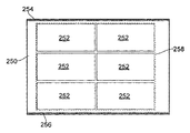
図2に本発明による装置200の概略図を示す。図示のように、図1の装置と同様に、装置200は、基板、例えばガラスFPDシート250を受容および処理する機械210を備える。理解されるように、FPDシート250は、ガラス以外の材料、例えば、プラスチックから作製され得、当然ながら、複合材料から作製され得る。FPDシート250は領域252を複数備え、その領域252はそれぞれ、機械210によって(多くの実施形態ではさらに複数の機械によって)FPDを形成するように処理される(しかし、理解されるように、本発明は、フラットパネルディスプレイ以外の構成部品、例えば電子回路ボードおよび/またはフレキシブル電子回路の製造での使用にも適している。理解されるように、処理は、多くの異なるタスクのうちの1つまたは複数を含むことができる。例えば、FPDシート250の処理は、1つまたは複数の領域252の個々のセル/ピクセルに液晶を注入するステップ、例えば領域252の少なくとも一部の少なくとも1つの画像を取得することによって、欠陥/不具合に関して1つまたは複数の領域252を検査するステップ、および/または例えばレーザを用いて破損したピクセルを取り除くことによって、領域252の少なくとも一部を修理するステップを含むことができる。機械210は、FPDシート250がその上に載せられるプラットフォーム212と、第1の垂直の柱および第2の垂直の柱116ならびにそれらの間を延びる横材218を備えるガントリ214とを備える。横材218は、基板処理部、例えば(例えばレーザまたは検査カメラなどの)ツール222がその上に載せられるツールホルダ220を携持する。従来技術の機械に関連して上記で説明したように、例えば1つのツールホルダ120または複数のツールホルダによって、ガントリ上に複数のツールが取り付けられ得る。さらに、1つの機械上にガントリが複数設けられ得る。制御システム230の制御下で、ガントリ214は、矢印Aで示すように、ベアリングおよびモータ(図示せず)によって、プラットフォーム212に沿ってy方向に移動することができ、ツールホルダ220は、矢印Bで示すように、ベアリングおよびモータ(図示せず)によって、横材218に沿ってx方向に移動することができる。理解されるように、他の実施形態では、ツールホルダ120は、横材118に対してz方向に、すなわちプラットフォーム112から垂直に離れるように、かつプラットフォーム112に垂直に向かうように移動することもできる。したがって、ツール222は、FPDシート250に対して、少なくとも2つの直交する方向に移動することができる。
FIG. 2 shows a schematic diagram of an
機械210の様々な可動部品の相対位置を判定する位置測定エンコーダが設けられている。例えば、図示しないが、x方向におけるそれらの相対位置を制御システム230にレポート可能にするように、ツールホルダ220および横材218上に読取りヘッド/スケール機構が設けられている。図1に示す実施形態とは異なり、プラットフォーム212の側面には、y方向におけるプラットフォーム212に対するガントリ214の位置の測定を可能にするためのスケールは取り付けられていない。そうではなく、図2に(さらに図3にも)示すように、FPDシート250の上面には、第1の方向にFPDシート250の対向する縁部に沿って延びる第1の計測スケール254および第2の計測スケール256が設けられている。第1のスケール254および第2のスケール256はそれぞれ、一連の絶対位置マーキングを備える。説明している実施形態では、第1のスケール254の一連のマーキングは第2のスケール256の一連のマーキングと同一であるが、必ずしもそのようにする必要があるとは限らない。
A position measurement encoder is provided that determines the relative positions of the various moving parts of the
さらに、図2から理解できるように、一方の柱216の内側に取り付けられた第1の読取りヘッド226と、他方の柱216の内側に取り付けられた第2の読取りヘッド228とが設けられており、そのため、FPDシート250が機械210のプラットフォーム212上に載せられるときに、第1の読取りヘッド226は第1のスケール254上の読取り位置に配置され第2の読取りヘッド228は第2のスケール256上の読取り位置に配置される。したがって、y方向におけるガントリ214(したがってツール222)とFPDシート250との相対位置は、第1の読取りヘッド224および第2の読取りヘッド228の出力によって判定およびモニタリングされ得る。
Further, as can be understood from FIG. 2, a
第1のスケール254および第2のスケール256の長さに平行な方向(すなわち図2の構成のy方向)におけるFPDシート250に対するツール222の位置は、第1のスケール254および第2のスケール256の長さに平行な方向において、FPDエリア252の配列によって画定されるエリア全体に関してモニタリングされ得る。この理由は、、図示のように、第1のスケール254および第2のスケール256が、FPDエリア252によって画定された(点線258で囲まれたエリアによって示されている)エリアの、第1のスケール254および第2のスケール256の長さに平行な方向にとった長さと少なくとも同じ長さであるからである。実際には、説明および図示の説明している実施形態では、第1のスケール254および第2のスケール256はFPDシート250の全長にわたって延びる。
The position of the
所望の場合は、例えばガントリ214およびプラットフォーム212上に、プラットフォーム212に対するガントリ214の位置を判定するための追加の位置測定エンコーダが設けられ得、そのためそれらの位置が判定され得る。例えば、図1に示すものと同様に構成された追加の読取りヘッドおよびスケールを設けられ得る。それにより、プラットフォーム212上にFPDシート250が載せられていないときにも、プラットフォーム212に対するガントリ214の位置を判定することが可能になる。それは、ガントリ214がプラットフォーム212の端部に近づいているときにそのことを判定するために使用することもできる。任意選択では、それは、フラットパネルディスプレイエリアのうちの処理される領域にツール222を動かすために使用することもできる。しかし、そのような場合でも、制御システム230は、ツール222がフラットパネルディスプレイエリアを処理できる位置にあるときの少なくともある時点で、FPDシート250上のスケール254、256を読み取る読取りヘッド226、228からの読取り値を使用し、こうすることで、処理されるフラットパネルディスプレイエリアに対してツール222がより正確に繰り返し可能に配置されるからである。例えば、ツール222が撮像ユニットである場合は、画像が撮られるときのFPDシート250とツール222との相対位置でFPDシート250上のスケール254、256からの読取り値が取られ得、そのため、ツール222とFPDシートとの相対位置のより正確な判定が行われ得る。代替的実施形態では、例えばツール222が少なくとも1つのフラットパネルディスプレイエリアを加工するツールである場合は、処理されるフラットパネルディスプレイエリア近傍にツール222が移動しているときには、追加の位置測定エンコーダからの読取り値が制御システムにフィードバックを行うように使用され得るが、それがフラットパネルディスプレイエリアを加工できる位置にあるときには、ツール222とFPDシート250との相対位置の測定値は、それらの相対位置に対してより優れた正確な制御を行うために、FPDシート250上のスケール254、256から取られ、ツール222とFPDシート250との相対位置を制御するために使用され得る。したがって、FPDシート250自体の上にあるスケール254、256が重要な瞬間に使用されて相対的な位置決めが確実に正確に行われるので、こうした追加の位置測定エンコーダは、図1の機械上に設けられるものよりもずっと安く簡素なものにしてもよい。実際は、こうした位置の測定値は、y方向におけるプラットフォームに対するガントリ214を移動させるモータ(複数可)のホールセンサによって提供され得る。
If desired, additional position measurement encoders can be provided on the
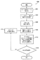
本発明によるFPDを製造する例示的な処理400に含まれるステップが図4に示されている。処理400は、第1のスケール254および第2のスケール256がFPD250上に(すなわち図2および図3に示すような)その対向する縁部に沿って形成されるステップ402で開始する。これは、スケールマーキングをガラス基板上に施す標準的な既知の処理を用いてガラスFPDシート250上に塗布され得る。例えば、金属材料(例えばクロム)がFPDシートに堆積され、次いで、レジスト材料の層でカバーされる、フォトリソグラフィ法が用いられ得る。次いで、フォトリソグラフィを用いて、レジストの一部を選択的に硬化させ、次いで未硬化の部分を洗い流すことができる。次いで、露出したクロムがエッチングされそのエッチングステップの後に残りのレジストが取り除かれる、エッチング法を用いることができる。残るのは、(クロムがエッチングされた)低反射の特徴部およびエッチングステップ中にクロムがレジストでカバーされた(比較的)高反射の特徴部を有するスケールである。理解されるように、FPDシート上にスケールマーキングを塗布するのに他の多くの技法が使用され得る。例えば、特許文献2に記載されている技法を用いるなどアブレーションによって、FPDガラスにスケールマーキングを形成するためにレーザが用いられ得る。他の代替的な方法はFPDシート250上に直接的に材料、例えば反射インクをプリントするステップを含むこともできる。
The steps involved in an
第1のスケール254および第2のスケール256がFPDシート250上に塗布されると、FPDシート250は試験機に送られる。(しかし、理解されるように、スケールを形成する機械と試験機とは同じ機械でよい。実際は、この同じ機械をFPDシートの処理のために使用することもできる)。試験機は、FPDシート250を受けるプラットフォームと、ガントリ上の図2に示すものと同様の、プラットフォームに沿って移動できる第1の読取りヘッドおよび第2の読取りヘッドとを有し、読取りヘッドが、プラットフォーム上に載せられるFPDシート上の第1のスケール254および第2のスケール256を読み取るという点で図2に示すものと同様である。しかし、それは、プラットフォームに対する読取りヘッドの位置を測定する追加の予め較正された装置を有することもできる。例えば、(例えば図1に示すものと同様に)少なくとも1つの追加の読取りヘッド/スケール一式を設けてもよい。任意選択では、プラットフォームに対する第1(および第2)の読取りヘッドの移動を正確に追跡するレーザ干渉システムを設けてもよい。プラットフォーム上に載せられたFPDシートはプラットフォームに対して静止した状態に維持され、FPDシートに対する第1(および第2)の読取りヘッドの移動は第1のスケール254および第2のスケール256によって測定される。第1のスケール254(および第2のスケール256)によって得られる測定値は、追加の測定装置(例えばレーザ干渉計)によって与えられた測定値と比較される。それら2つの間のいかなる誤差も、FPDシート上にプリントされたスケールの誤差のせいであると想定され得、したがって、FPDシートに関する誤差マップおよび/または誤差関数は、以下により詳細に説明するように後から使用するために生成および格納され得る。例えば、誤差マップおよび/または誤差関数は、FPDシートを処理するのに用いられる各機械と通信できるセントラルサーバまたはデータベースに格納され得る。
When the
誤差マップおよび/または誤差関数がFPDシート250に関して生成された後で、本方法は、FPDシート250が機械210上に載せられるステップ406に進む。これは、例えば操作者が手でまたは機械類の助けで試験機からのFPDシート250の持ち上げを制御し、FPDシート250を処理する機械210上にFPDシート250を配置することによって、手動で行われ得る。任意選択では、これは自動的に行われ得る。例えば、FPDシート250は、FPDシート250を摘み上げ、移動させ、配置するように構成されたロボットアームなど、適切な運搬機構によって、試験機からFPDシート250を処理する機械まで搬送され得る。
After the error map and / or error function is generated for the
ステップ408では、機械210は、その上に載せられたFPDシート250に関する誤差マップおよび/または誤差関数を検索する。(理解されるように、誤差マップおよび/または誤差関数は、FPDシート250が機械上に載せられる前、載せられた後、または載せられている途中に検索され得る)。説明している実施形態では、誤差マップおよび/または誤差関数は、機械が処理するFPDシート全てに関する全ての誤差マップおよび/または誤差関数を格納するセントラルサーバから検索される。当然ながら、他の実装形態が可能である。例えば、機械210は、それ自体が、FPDシート250およびそれが処理する他の任意のFPDシートに関する誤差マップおよび/または誤差関数を格納することができる。したがって、FPDシートを載せる際に、機械210は、そのローカルメモリから誤差マップおよび/または誤差関数を検索することができる。FPDシート250に関する誤差マップおよび/または誤差関数は、機械に関する以前に生成した誤差マップ(複数可)および/または誤差関数(複数可)があればそれと組み合わせられ得、それにより、機械構成、さらにFPDシート250の第1のスケール254および第2のスケール256によって起きた誤差を補償することが可能になる。
In
次いで、機械210は、ステップ410でその所定のルーチンに従ってFPDシート250を処理する。例えば、機械は、ツール222を用いて1つまたは複数の領域252の個々のセル/ピクセルに液晶を注入し、例えば領域252の少なくとも一部の少なくとも1つの画像を取得することによって欠陥/不具合について1つまたは複数の領域252を検査し、かつ/または例えばレーザを用いて破損したピクセルを取り除くことによって、領域252の少なくとも一部を修理することもできる。理解されるように、これは、ツールを適切な位置に配置するために、FPDシート250に対するツール222の移動を含む。処理動作中は、y軸におけるFPDシート250に対するツール222の位置は、FPDシート250上にプリントされた第1のスケール254および第2のスケール256を読み取る第1の読取りヘッド226および第2の読取りヘッド228の出力を用いてモニタリングされる。誤差マップおよび/または誤差関数を用いて、第1の読取りヘッド226および第2の読取りヘッド228から得られた測定値を補正する。その位置はFPDシート250自体から直接測定されるので、処理動作前におよび/またはその途中でFPDシート250がプラットフォームに対して移動しかつ/または熱膨張/熱収縮を受ける場合でも、y方向におけるFPDシート250に対するツール222の位置は正確に分かる。さらに、y方向においてプラットフォーム212上のFPDシート250の好ましい位置があってよい。好ましい位置からのFPDシート250のずれがある場合はそれが、FPDシート自体の上の第1のスケール254および第2のスケール256から判定され得る。機械のセットアップに応じて、これは、機械自体の上にあるエンコーダ/位置センサからの情報を必要とすることもある。こうした長手方向のずれがある場合はそれが、第1のスケール254および第2のスケール256を用いてFPDシート250を好ましい位置に戻すことによって低減される、もしくはなくなることもあり、かつ/またはそのずれが制御システム230によって自動的に補償されることもある。
The
機械210上でFPDシート250の処理が完了すると、ステップ412ではFPDシート250が後続の機械でさらに処理を必要とするか否かが判定される。実際は、FPDシート250は、それぞれのタスク(複数可)の処理を実行するようにそれぞれ構成された図2に示すのと同様の多くの機械によって処理されることが必要とされ得る。例えば、ある機械は領域252のピクセルに液晶を注入するように、別の機械は領域252のピクセルを検査するように、別の機械は領域252のピクセルを修理するように構成され得る。理解されるように、これらは単なる例であり、FPD製造ラインにはこうした機械がいくつも存在してよい。
When processing of the
後続の機械で処理が必要とされる場合は、FPDシート250は、ステップ414では、次の機械に(第1の機械210上にFPDシート250を載せることに関連して上記で説明したように手動でまたは自動的に)載せられる。次いで、こうした後続の機械は、ステップ408では(例えばセントラルサーバからまたはローカルメモリデバイスから)誤差マップおよび/または誤差関数を検索し、ステップ410ではその専用の処理動作に従ってFPDシート250を処理する。上記と同じく、これは、(誤差マップおよび/または誤差関数を用いて補正された)第1の読取りヘッド226および第2の読取りヘッド228の出力によって、後続の機械がy軸におけるFPDシートに対するガントリ上でのこうしたツールの位置を判定するステップを含む。ステップ408から414は、製造ラインの最後の機械によってFPDシート250の全ての処理が完了するまで続く。
If processing is required on a subsequent machine, the
図5に、図2に示すものと同様の本発明の代替的実施形態を示す。同様の部品は同様の参照番号を共有している。図5に示す実施形態は、FPDシート350がその一方の縁部に沿って設けられたスケール254を1つしか有しないという点で、図2に示すものとは異なる。理解されるように、y方向におけるツール222とFPDシート350との相対位置を追跡するためにスケールは1つしか必要とされない。それでも、以下により詳細に説明するように、2つのスケールをFPDシート250、350の対向する縁部にそれぞれ1つずつ設けることは、特にシートがプラットフォーム212上で完璧に位置合わせされないときには、ツールとFPDシートとの相対位置のより正確な測定値を得るために効果的な場合がある。図5の実施形態は、スケール254を読み取る読取りヘッド226がガントリ214の垂直の柱216上にアーム352を介して取り付けられている点でも異なる。アーム352は、旋回式の接続部を介して垂直の柱216に取り付けられており、そのため、読取りヘッド226がその読取り位置から矢印Aで示す向きに旋回することができる。このように読取りヘッド226が後退することで、プラットフォーム212にFPDシート350を載せる/降ろすことならびに機械310および読取りヘッド226のメンテナンス(例えば洗浄)を助けることができる。理解されるように、図2の実施形態に示す読取りヘッド226、228の一方または両方をこうした引き込み式のアームを介してガントリ214上に取り付けられ得る。
FIG. 5 shows an alternative embodiment of the invention similar to that shown in FIG. Similar parts share similar reference numbers. The embodiment shown in FIG. 5 differs from that shown in FIG. 2 in that the
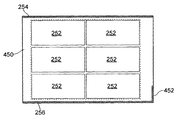
図6に本発明の別の実施形態によるFPDシート450の平面図を示す。図2および図3に示す実施形態と同様に、FPDシート450は、複数のFPDエリア252と、FPDシート450の対向する長手方向の縁部に沿って延びる第1のスケール254および第2のスケール256とを備える。しかし、図6に示すFPDシート450は第3のスケール452も備え、第3のスケール452は、その一方の端部でFPDシート450の幅の一部分にわたって第1のスケール254および第2のスケール256に垂直に延びる。これは、機械のプラットフォーム上に載せられたFPDシート450の横方向の位置がFPDシートの処理を始める前に判定可能になるように、ガントリに、具体的には機械の垂直の柱116に取り付けられた、固定式のアームに取り付けられた読取りヘッドによって読み取られ得る。したがって、FPDシート450の横方向のずれがあればそれが第3のスケール452を用いて補償され得る。理解されるように、他の実施形態では、第2のスケール452のための読取りヘッドは、ツールホルダ120上にまたはプラットフォーム112上にも設けられ得る。さらに、第3のスケール452は、FPDシート250の幅のうちの大部分、例えばFPDシート250の幅全体にわたって延びることもできる。第3のスケール452は、必ずしもFPDシート250の端部に配置される必要があるとは限らない。例えば、それは、FPDシート250に沿った途中の位置に、例えば領域252間に配置され得る。同じことが第1のスケール254および第2のスケール256にも適用可能であり、例えばそれらをFPDシート250の縁部に配置する必要はないが、縁部から離れた位置、例えば領域252の間に配置することもできる。さらに他の実施形態では、x方向とy方向の両方における位置情報を提供するために使用され得る2方向のスケールがFPDシート250上に形成され得る。例えば、グリッド様のスケールが、FPDシート250の下面に設けられ得、FPDシート250の下方に、例えばプラットフォームに配置された少なくとも1つの読取りヘッドによって読み取られ得る。2方向のスケールは、それがFPDシート250から取り除かれ得るように構成され得、例えば、スケールは、領域252が化学物質を用いて処理された後で洗い流され得る一時的なスケールとすることもできる。
FIG. 6 shows a plan view of an
図7に、機械210のプラットフォーム212上に載せられた図2および図3のFPDシート250の平面図を示す(単純にするために、図7にはガントリ214は示していないが第1の読取りヘッド226および第2の読取りヘッド228は示している)。理解され得るように、FPDシート250は、プラットフォームの平面に垂直な軸を中心に回転方向にずれるようにしてプラットフォーム上に載せられている。しかし、FPDシート250が回転方向にずれているので、回転方向のずれの角度は、第1の読取りヘッド226および第2の読取りヘッド228の出力によって判定され得る。実際は、図7に示すように、回転方向のずれのせいで、第1の読取りヘッドおよび第2の読取りヘッド228は、第1のスケール254および第2のスケール256の長さに沿って異なる点にあり、その差は、回転方向のずれの角度θ(例えば、図7に示すように、FPDシート250の長手方向の辺の間を垂直に延びる線260と、第1の読取りヘッド226と第2の読取りヘッド228との間を垂直に延びる線262との間の角度)を判定するために使用され得る。次いで、FPDシート250の位置は、回転方向のずれを低減する、もしくはなくすように調整することもでき、かつ/または制御システム230は、ずれを判定し読み取り、位置に関する誤差があればそれを計算し、処理動作中にその回転方向のずれを補償することができる。回転方向のずれが制御システム230によって単に補償されるか、または回転方向のずれがFPDシート250を移動させることによって低減されるかは、読取りヘッドがスケールから横方向にはみ出すことなしに補償され得る最大のずれ(読取りヘッド窓のサイズおよびスケールの幅に依存することができる)に基づくことができる。
FIG. 7 shows a top view of the
図8に、フレキシブル基板300上に複数の構成部品が作製され各構成部品が基板上の構成部品エリア302内に作製される、本発明の代替的実施形態を示す。それらの構成部品はオープンリール処理機械上で製造され、したがって、基板は、上記で説明した他の実施形態に示すようなプラットフォームに対向する、機械上の一連のリールまたはローラ304によって支持されそれによって移動する。オープンリール処理機械は、本発明の他の実施形態に関連して上記で説明したものと同様のツールなどの基板処理部(図示せず)も有し、基板処理部はオープンリール処理の少なくとも1つの段階で少なくとも1つの構成部品エリアを(例えば検査によってまたは少なくとも1つの構成部品エリアを加工することによって)処理する。他の実施形態に関連して上記で説明したものと実質的に同じ計測スケール306がフレキシブル基板300上に設けられ、基板300の長さに沿って第1の方向に延びる。基板処理部と基板300との相対位置を判定可能にするように、基板処理部に関連付けられた、計測スケール306を読み取る読取りヘッド(図示せず)が設けられる。
FIG. 8 illustrates an alternative embodiment of the present invention in which multiple components are fabricated on a
上記で説明した実施形態では、第1のスケール254および第2のスケール256は、一連の絶対位置を定め、アブソリュートスケールとして通常知られている(例えば特許文献3および特許文献4参照)。しかし、必ずしもそのようにする必要があるとは限らない。例えば、第1のスケール254および/または第2のスケール256は、(基準マーク位置ありまたはなしの)インクリメンタルスケール(例えば特許文献5および特許文献6参照)を備えることもできる。
In the embodiment described above, the
上記で説明した実施形態では、第1のスケール254および第2のスケール256は、連続した一連の特徴部によって設けられている。しかし、理解されるように、必ずしもそのようにする必要があるとは限らない。例えば、第1のスケール254および第2のスケール256は、FPDガラスの長さに沿って離間した一連の別々の群のスケール特徴部によって設けられ得る。例えば、第1のスケール254および第2のスケール256に、例えば異なる領域252間の隙間に、隙間がある場合がある。
In the embodiment described above, the
上記で説明した実施形態では、スケールはFPDシート250の上面に形成されており、その上面はFPDシート250のうちのそれがその上に載せられる機械で処理される側である。しかし、スケールは、FPDシート250の下側に形成され得る。この場合は、読取りヘッドは、FPDシート250を通してスケールを読み取るように構成され得、FPDシート250の下からスケールを読み取るように配置され得る。さらなる実施形態では、FPDシート250の垂直の縁部上に、すなわちFPDシート250のリム上に、少なくとも1つのスケールが設けられ得る。
In the embodiment described above, the scale is formed on the top surface of the
さらに、上記で説明した実施形態では、スケールはFPDシート250上に永久に形成されている。それらは、それらが領域252に位置しないので領域250に形成される最終製品に干渉しない。他の実施形態では、スケールは、例えば非永久インクを用いてスケールをFPDシート250上にプリントすることによって、FPDシート250上に一時的に形成され得る。処理後に、スケールマーキングは、適切な化学薬品を用いて洗い流すことによって除去され得る。これにより、領域252自体を含むFPDシート250上のどこにでもスケールを配置可能にすることができる。
Furthermore, in the embodiment described above, the scale is permanently formed on the
さらに、上記で説明した実施形態は、領域252がFPDシート250上に複数設けられることを説明している。しかし、理解されるように、FPDシート250上に設けられる領域が1つしかなくてもよい。
Further, the embodiment described above describes that a plurality of
さらに、上記で説明した実施形態は、基板250、300上の全ての領域252、302のために使用される第1(および任意選択では第2)のスケール254、306(256)を備える。しかし、理解されるように、異なる領域252、302のために別々のスケールが設けられ得る。例えば、各領域252、302に個々のスケールが1つ設けられ得る。任意選択では、第1の群の領域には少なくとも1つのスケールが、第2の群の領域には少なくとも1つの他のスケールが設けられ得る。
Furthermore, the embodiments described above comprise first (and optionally second) scales 254, 306 (256) that are used for all
Claims (24)
少なくとも前記基板処理部および基板は前記基板処理部が前記基板上の前記少なくとも1つの構成部品エリアを処理できる位置関係にあるときに、前記基板によって提供された少なくとも第1の計測スケールを読み取ることによって前記基板に対する前記基板処理部の位置を測定するステップ
を含むことを特徴とする方法。 A method of manufacturing at least one component in at least one component area on a substrate using a machine having a substrate processing section movable relative to the substrate,
By reading at least a first measurement scale provided by the substrate when the substrate processing unit and the substrate are in a positional relationship where the substrate processing unit can process the at least one component area on the substrate A method comprising measuring a position of the substrate processing unit with respect to the substrate.
を含むことを特徴とする請求項1または2に記載の方法。 The control system receives position information from a position sensor on the machine that reads the at least first measurement scale, and performs relative movement between the substrate processing unit of the machine and the substrate based on the position information. 3. A method according to claim 1 or 2, comprising the step of controlling.
をさらに含むことを特徴とする前記請求項のいずれかに記載の方法。 Generating an error map and / or an error function for the at least first measurement scale, and correcting the measured value of the relative position between the substrate processing unit of the machine and the substrate using the error map or the error function; The method according to any of the preceding claims, further comprising the step of:
基板の少なくとも1つの構成部品エリアを処理する基板処理部を備える機械であって、前記基板処理部および基板が互いに対して移動可能であり、そのため、前記基板処理部が前記基板上の前記少なくとも1つの構成部品エリアを処理できる位置関係に移動できる、機械と、
前記基板処理部および基板がこうした位置関係にあるときに位置センサが前記基板によって提供されたスケールを読み取ることができるように構成された少なくとも1つの位置センサと、
前記少なくとも1つの位置センサからの読取り値を受信し前記基板処理部と前記少なくとも1つの構成部品エリアとの相対位置を測定するように構成された制御システムと
を備えることを特徴とする装置。 An apparatus for producing at least one component on a substrate,
A machine comprising a substrate processing unit for processing at least one component area of a substrate, wherein the substrate processing unit and the substrate are movable relative to each other, so that the substrate processing unit is located on the substrate A machine that can be moved into a positional relationship that can handle one component area,
At least one position sensor configured to allow the position sensor to read a scale provided by the substrate when the substrate processing section and the substrate are in such a positional relationship;
An apparatus comprising: a control system configured to receive a reading from the at least one position sensor and measure a relative position between the substrate processing unit and the at least one component area.
前記少なくとも第1の計測スケールを使用して、前記基板と、前記少なくとも1つの構成部品エリアのうちの少なくとも1つを処理するのに使用される機械の基板処理部との相対位置をモニタリングする
ことを特徴とする構成部品を製造する方法。 Incorporating a substrate comprising at least one component area, the substrate having at least a first metrology scale comprising a series of position markings extending along the substrate;
Monitoring the relative position of the substrate and a substrate processing section of a machine used to process at least one of the at least one component area using the at least first metrology scale. A method of manufacturing a component characterized by:
前記基板を少なくとも1つの処理機械上に載せるステップと、
前記基板のスケールに関する前記誤差マップおよび/または誤差関数を前記少なくとも1つの機械に供給するステップと
を含み
前記機械は、前記加工物の処理中に前記基板のスケールおよび前記誤差マップおよび/または誤差関数を用いる
ことを特徴する方法。 Generating an error map and / or an error function for a measurement scale placed on the substrate;
Placing the substrate on at least one processing machine;
Providing said error map and / or error function for said substrate scale to said at least one machine, said machine comprising said substrate scale and said error map and / or error function during processing of said workpiece A method characterized by using.
Applications Claiming Priority (3)
| Application Number | Priority Date | Filing Date | Title |
|---|---|---|---|
| EP11250638 | 2011-07-06 | ||
| EP11250638.1 | 2011-07-06 | ||
| PCT/GB2012/000569 WO2013004992A1 (en) | 2011-07-06 | 2012-07-05 | Method of manufacture and apparatus therefor |
Publications (2)
| Publication Number | Publication Date |
|---|---|
| JP2014526140A true JP2014526140A (en) | 2014-10-02 |
| JP2014526140A5 JP2014526140A5 (en) | 2015-08-06 |
Family
ID=44511797
Family Applications (1)
| Application Number | Title | Priority Date | Filing Date |
|---|---|---|---|
| JP2014517910A Pending JP2014526140A (en) | 2011-07-06 | 2012-07-05 | Manufacturing method and manufacturing apparatus |
Country Status (7)
| Country | Link |
|---|---|
| US (1) | US20140123458A1 (en) |
| EP (1) | EP2729427A1 (en) |
| JP (1) | JP2014526140A (en) |
| KR (1) | KR20140039245A (en) |
| CN (1) | CN103619770A (en) |
| TW (1) | TWI502672B (en) |
| WO (1) | WO2013004992A1 (en) |
Families Citing this family (18)
| Publication number | Priority date | Publication date | Assignee | Title |
|---|---|---|---|---|
| JP5920943B2 (en) * | 2013-04-18 | 2016-05-18 | エーピー システムズ インコーポレイテッド | Horizontal beam for cradle and substrate processing apparatus using the same |
| CA2952633C (en) | 2014-06-20 | 2018-03-06 | Velo3D, Inc. | Apparatuses, systems and methods for three-dimensional printing |
| KR101720574B1 (en) * | 2014-12-12 | 2017-03-29 | 주식회사 이오테크닉스 | Apparatus laser processing and method for driving the same |
| US10065270B2 (en) | 2015-11-06 | 2018-09-04 | Velo3D, Inc. | Three-dimensional printing in real time |
| US10183330B2 (en) | 2015-12-10 | 2019-01-22 | Vel03D, Inc. | Skillful three-dimensional printing |
| US10252335B2 (en) | 2016-02-18 | 2019-04-09 | Vel03D, Inc. | Accurate three-dimensional printing |
| US10286452B2 (en) | 2016-06-29 | 2019-05-14 | Velo3D, Inc. | Three-dimensional printing and three-dimensional printers |
| US11691343B2 (en) | 2016-06-29 | 2023-07-04 | Velo3D, Inc. | Three-dimensional printing and three-dimensional printers |
| US20180093419A1 (en) | 2016-09-30 | 2018-04-05 | Velo3D, Inc. | Three-dimensional objects and their formation |
| US20180126462A1 (en) | 2016-11-07 | 2018-05-10 | Velo3D, Inc. | Gas flow in three-dimensional printing |
| US20180186082A1 (en) | 2017-01-05 | 2018-07-05 | Velo3D, Inc. | Optics in three-dimensional printing |
| US10442003B2 (en) | 2017-03-02 | 2019-10-15 | Velo3D, Inc. | Three-dimensional printing of three-dimensional objects |
| CN106938371A (en) * | 2017-03-16 | 2017-07-11 | 广东工业大学 | A kind of high-precision laser cutting machine and its crossbeam |
| US20180281237A1 (en) | 2017-03-28 | 2018-10-04 | Velo3D, Inc. | Material manipulation in three-dimensional printing |
| US10272525B1 (en) | 2017-12-27 | 2019-04-30 | Velo3D, Inc. | Three-dimensional printing systems and methods of their use |
| US10144176B1 (en) | 2018-01-15 | 2018-12-04 | Velo3D, Inc. | Three-dimensional printing systems and methods of their use |
| CN110508948A (en) * | 2018-05-22 | 2019-11-29 | 佛山市嘉实和生物科技有限公司 | A kind of multifunctional combination laser equipment |
| WO2021021469A1 (en) | 2019-07-26 | 2021-02-04 | Velo3D, Inc. | Quality assurance in formation of three-dimensional objects |
Citations (6)
| Publication number | Priority date | Publication date | Assignee | Title |
|---|---|---|---|---|
| JPH11281320A (en) * | 1998-03-30 | 1999-10-15 | Jasco Corp | Position sensing apparatus |
| JP2004337726A (en) * | 2003-05-14 | 2004-12-02 | Seiko Epson Corp | Droplet discharging apparatus, electro-optical device production method, electro-optical device, electronic device, and substrate |
| JP2006178463A (en) * | 2004-12-22 | 2006-07-06 | Asml Netherlands Bv | Lithographic apparatus, method of manufacturing device, and device manufactured thereby |
| JP2007012426A (en) * | 2005-06-30 | 2007-01-18 | Optrex Corp | Organic el display panel, its manufacturing and inspection methods |
| WO2008029757A1 (en) * | 2006-09-01 | 2008-03-13 | Nikon Corporation | Mobile object driving method, mobile object driving system, pattern forming method and apparatus, exposure method and apparatus, device manufacturing method and calibration method |
| JP2010510672A (en) * | 2006-11-15 | 2010-04-02 | ザイゴ コーポレーション | Distance measuring interferometer and encoder measuring system used in lithography tools |
Family Cites Families (10)
| Publication number | Priority date | Publication date | Assignee | Title |
|---|---|---|---|---|
| GB8616240D0 (en) * | 1986-07-03 | 1986-08-13 | Renishaw Plc | Opto-electronic scale reading apparatus |
| JPH0360437A (en) * | 1989-07-26 | 1991-03-15 | Hitachi Ltd | Cutting mark |
| US5279044A (en) | 1991-03-12 | 1994-01-18 | U.S. Philips Corporation | Measuring device for determining an absolute position of a movable element and scale graduation element suitable for use in such a measuring device |
| GB0109057D0 (en) | 2001-04-11 | 2001-05-30 | Renishaw Plc | Absolute postition measurement |
| WO2003001891A2 (en) | 2001-06-28 | 2003-01-09 | Entelos, Inc. | Method and apparatus for computer modeling of an adaptive immune response |
| JP2005326550A (en) * | 2004-05-13 | 2005-11-24 | Sanee Giken Kk | Exposure device |
| GB0413710D0 (en) | 2004-06-21 | 2004-07-21 | Renishaw Plc | Scale reading apparatus |
| WO2007044798A2 (en) * | 2005-10-11 | 2007-04-19 | Gsi Group Corporation | Optical metrological scale and laser-based manufacturing method therefor |
| GB2438600B (en) * | 2006-05-19 | 2008-07-09 | Exitech Ltd | Method for patterning thin films on moving substrates |
| US8294878B2 (en) * | 2009-06-19 | 2012-10-23 | Nikon Corporation | Exposure apparatus and device manufacturing method |
-
2012
- 2012-07-05 WO PCT/GB2012/000569 patent/WO2013004992A1/en active Application Filing
- 2012-07-05 US US14/127,104 patent/US20140123458A1/en not_active Abandoned
- 2012-07-05 JP JP2014517910A patent/JP2014526140A/en active Pending
- 2012-07-05 CN CN201280031693.XA patent/CN103619770A/en active Pending
- 2012-07-05 KR KR1020137035168A patent/KR20140039245A/en not_active Application Discontinuation
- 2012-07-05 EP EP12737851.1A patent/EP2729427A1/en not_active Withdrawn
- 2012-07-06 TW TW101124511A patent/TWI502672B/en not_active IP Right Cessation
Patent Citations (6)
| Publication number | Priority date | Publication date | Assignee | Title |
|---|---|---|---|---|
| JPH11281320A (en) * | 1998-03-30 | 1999-10-15 | Jasco Corp | Position sensing apparatus |
| JP2004337726A (en) * | 2003-05-14 | 2004-12-02 | Seiko Epson Corp | Droplet discharging apparatus, electro-optical device production method, electro-optical device, electronic device, and substrate |
| JP2006178463A (en) * | 2004-12-22 | 2006-07-06 | Asml Netherlands Bv | Lithographic apparatus, method of manufacturing device, and device manufactured thereby |
| JP2007012426A (en) * | 2005-06-30 | 2007-01-18 | Optrex Corp | Organic el display panel, its manufacturing and inspection methods |
| WO2008029757A1 (en) * | 2006-09-01 | 2008-03-13 | Nikon Corporation | Mobile object driving method, mobile object driving system, pattern forming method and apparatus, exposure method and apparatus, device manufacturing method and calibration method |
| JP2010510672A (en) * | 2006-11-15 | 2010-04-02 | ザイゴ コーポレーション | Distance measuring interferometer and encoder measuring system used in lithography tools |
Also Published As
| Publication number | Publication date |
|---|---|
| KR20140039245A (en) | 2014-04-01 |
| TW201312685A (en) | 2013-03-16 |
| US20140123458A1 (en) | 2014-05-08 |
| TWI502672B (en) | 2015-10-01 |
| WO2013004992A1 (en) | 2013-01-10 |
| CN103619770A (en) | 2014-03-05 |
| EP2729427A1 (en) | 2014-05-14 |
Similar Documents
| Publication | Publication Date | Title |
|---|---|---|
| JP2014526140A (en) | Manufacturing method and manufacturing apparatus | |
| TWI627887B (en) | Method and apparatus for automatically adjusting dispensing units of a dispenser | |
| JP5562424B2 (en) | Device for aligning two substrates | |
| KR102166641B1 (en) | Self-diagnosis of machine and method for precision calibration of machine | |
| TWI610341B (en) | Imprint apparatus, imprint system, and method of manufacturing article | |
| US8934081B2 (en) | Method and apparatus for performing alignment using reference board | |
| KR101362638B1 (en) | Exposure apparatus | |
| JP6457773B2 (en) | Imprint method, imprint apparatus and article manufacturing method | |
| KR20100055321A (en) | Alignment apparatus for inspection substrate | |
| JP2014241398A (en) | Imprint device, device manufacturing method, and imprint method | |
| JP2014524038A (en) | Alignment system for various materials and material flows | |
| JP2016205957A (en) | Method for correcting movable head position of x-y substrate inspection device, and x-y substrate inspection device | |
| CN107615450A (en) | Imprinting apparatus, method for stamping and the method for manufacturing product | |
| CN112695272B (en) | Mask manufacturing device and method | |
| JP5943523B2 (en) | Contact circuit pattern inspection apparatus and inspection method thereof | |
| JP2021531964A (en) | Systems and methods to transition from synchronous supply to asynchronous supply | |
| EP3680105B1 (en) | Screen printing machine | |
| KR101387312B1 (en) | Proximity exposure apparatus, method for determining a substrate position in the proximity exposure apparatus and method of manufacturing a display panel substrate | |
| JP2016205958A (en) | Method for correcting movable head position of x-y substrate inspection device, and x-y substrate inspection device | |
| US20090284719A1 (en) | Alignment method and apparatus of mask pattern | |
| CN107976869B (en) | Workpiece table non-orthogonal correction method and correction device | |
| JP5884273B2 (en) | Exposure unit and substrate pre-alignment method | |
| KR20130042367A (en) | Method for compensating position of measuring device on xy stage |
Legal Events
| Date | Code | Title | Description |
|---|---|---|---|
| A521 | Request for written amendment filed |
Free format text: JAPANESE INTERMEDIATE CODE: A523 Effective date: 20150617 |
|
| A621 | Written request for application examination |
Free format text: JAPANESE INTERMEDIATE CODE: A621 Effective date: 20150617 |
|
| A977 | Report on retrieval |
Free format text: JAPANESE INTERMEDIATE CODE: A971007 Effective date: 20160707 |
|
| A131 | Notification of reasons for refusal |
Free format text: JAPANESE INTERMEDIATE CODE: A131 Effective date: 20160712 |
|
| A601 | Written request for extension of time |
Free format text: JAPANESE INTERMEDIATE CODE: A601 Effective date: 20161007 |
|
| A601 | Written request for extension of time |
Free format text: JAPANESE INTERMEDIATE CODE: A601 Effective date: 20161212 |
|
| A02 | Decision of refusal |
Free format text: JAPANESE INTERMEDIATE CODE: A02 Effective date: 20170307 |