KR20140039245A - Method of manufacture and apparatus therefor - Google Patents
Method of manufacture and apparatus therefor Download PDFInfo
- Publication number
- KR20140039245A KR20140039245A KR1020137035168A KR20137035168A KR20140039245A KR 20140039245 A KR20140039245 A KR 20140039245A KR 1020137035168 A KR1020137035168 A KR 1020137035168A KR 20137035168 A KR20137035168 A KR 20137035168A KR 20140039245 A KR20140039245 A KR 20140039245A
- Authority
- KR
- South Korea
- Prior art keywords
- substrate
- scale
- machine
- metrology
- processing portion
- Prior art date
Links
Images


Classifications
-
- B—PERFORMING OPERATIONS; TRANSPORTING
- B23—MACHINE TOOLS; METAL-WORKING NOT OTHERWISE PROVIDED FOR
- B23K—SOLDERING OR UNSOLDERING; WELDING; CLADDING OR PLATING BY SOLDERING OR WELDING; CUTTING BY APPLYING HEAT LOCALLY, e.g. FLAME CUTTING; WORKING BY LASER BEAM
- B23K26/00—Working by laser beam, e.g. welding, cutting or boring
- B23K26/08—Devices involving relative movement between laser beam and workpiece
- B23K26/083—Devices involving movement of the workpiece in at least one axial direction
- B23K26/0838—Devices involving movement of the workpiece in at least one axial direction by using an endless conveyor belt
- B23K26/0846—Devices involving movement of the workpiece in at least one axial direction by using an endless conveyor belt for moving elongated workpieces longitudinally, e.g. wire or strip material
-
- B—PERFORMING OPERATIONS; TRANSPORTING
- B23—MACHINE TOOLS; METAL-WORKING NOT OTHERWISE PROVIDED FOR
- B23K—SOLDERING OR UNSOLDERING; WELDING; CLADDING OR PLATING BY SOLDERING OR WELDING; CUTTING BY APPLYING HEAT LOCALLY, e.g. FLAME CUTTING; WORKING BY LASER BEAM
- B23K26/00—Working by laser beam, e.g. welding, cutting or boring
- B23K26/08—Devices involving relative movement between laser beam and workpiece
- B23K26/0869—Devices involving movement of the laser head in at least one axial direction
- B23K26/0876—Devices involving movement of the laser head in at least one axial direction in at least two axial directions
-
- B—PERFORMING OPERATIONS; TRANSPORTING
- B23—MACHINE TOOLS; METAL-WORKING NOT OTHERWISE PROVIDED FOR
- B23K—SOLDERING OR UNSOLDERING; WELDING; CLADDING OR PLATING BY SOLDERING OR WELDING; CUTTING BY APPLYING HEAT LOCALLY, e.g. FLAME CUTTING; WORKING BY LASER BEAM
- B23K26/00—Working by laser beam, e.g. welding, cutting or boring
- B23K26/352—Working by laser beam, e.g. welding, cutting or boring for surface treatment
- B23K26/355—Texturing
-
- B—PERFORMING OPERATIONS; TRANSPORTING
- B23—MACHINE TOOLS; METAL-WORKING NOT OTHERWISE PROVIDED FOR
- B23K—SOLDERING OR UNSOLDERING; WELDING; CLADDING OR PLATING BY SOLDERING OR WELDING; CUTTING BY APPLYING HEAT LOCALLY, e.g. FLAME CUTTING; WORKING BY LASER BEAM
- B23K26/00—Working by laser beam, e.g. welding, cutting or boring
- B23K26/36—Removing material
- B23K26/361—Removing material for deburring or mechanical trimming
-
- B—PERFORMING OPERATIONS; TRANSPORTING
- B23—MACHINE TOOLS; METAL-WORKING NOT OTHERWISE PROVIDED FOR
- B23P—METAL-WORKING NOT OTHERWISE PROVIDED FOR; COMBINED OPERATIONS; UNIVERSAL MACHINE TOOLS
- B23P25/00—Auxiliary treatment of workpieces, before or during machining operations, to facilitate the action of the tool or the attainment of a desired final condition of the work, e.g. relief of internal stress
-
- Y—GENERAL TAGGING OF NEW TECHNOLOGICAL DEVELOPMENTS; GENERAL TAGGING OF CROSS-SECTIONAL TECHNOLOGIES SPANNING OVER SEVERAL SECTIONS OF THE IPC; TECHNICAL SUBJECTS COVERED BY FORMER USPC CROSS-REFERENCE ART COLLECTIONS [XRACs] AND DIGESTS
- Y10—TECHNICAL SUBJECTS COVERED BY FORMER USPC
- Y10T—TECHNICAL SUBJECTS COVERED BY FORMER US CLASSIFICATION
- Y10T29/00—Metal working
- Y10T29/49—Method of mechanical manufacture
- Y10T29/49764—Method of mechanical manufacture with testing or indicating
- Y10T29/49771—Quantitative measuring or gauging
Abstract
기판에 대하여 상대적으로 이동 가능한 기판 처리부를 갖는 기계를 이용하여 기판 상의 적어도 하나의 컴포넌트 영역에서 적어도 하나의 컴포넌트를 제조하는 방법이 제공된다. 본 방법은, 적어도, 기판 처리부와 기판이, 기판 처리부가 상기 기판 상에 적어도 하나의 컴포넌트 영역을 처리할 수 있는 위치 관계에 있을 때, 적어도 기판에 의해 제공된 제1 계측 스케일을 판독함으로써 기판에 대한 기판 처리부의 위치를 측정하는 단계를 포함한다.A method is provided for manufacturing at least one component in at least one component region on a substrate using a machine having a substrate processing portion relatively movable relative to the substrate. The method includes at least a substrate processing unit and a substrate having at least a first measurement scale provided by the substrate when the substrate processing unit is in a positional relationship in which the processing unit can process the at least one component region on the substrate. Measuring the position of the substrate processing unit.
Description
본 발명은, 예를 들어 평판 디스플레이(FPD(flat panel display))인 전자 컴포넌트와 같은 컴포넌트를 제조하는 제조 방법 및 제조 장치에 관한 것이다.The present invention relates to a manufacturing method and a manufacturing apparatus for manufacturing a component such as an electronic component, for example, a flat panel display (FPD).
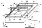
FPD와 같은 컴포넌트는 배치(batch)로 종종 제조되어, 예를 들어 복수의 개별 FPD가 동일한 유리 시트 상에 제조된다. 예를 들어, 도 1은 평판 디스플레이의 배치를 처리하기 위한 공지의 장치(100)에 대한 개략도를 제공한다. 특히, 장치는 FPD의 제조 동안 각각이 기계(110)(그리고, 많은 실시예에서는 복수의 추가적인 기계)에 의해 처리되는 복수의 영역(152)을 포함하는 FPD 시트(150)를 수용하여 처리하는 기계(110)를 포함한다. 기계(110)는 FPD 시트(150)가 로드되는 플랫폼(112)과, 제1 및 제2 직립 필러(pillar)(116)와 이들 사이에서 연장되어 도구(122)(예를 들어, 레이저, 액정 디스펜서 또는 검사 카메라)가 로드되는 도구 홀더(120)를 운반하는 크로스 부재(118)를 포함하는 갠트리(114)를 포함한다. (이해되는 바와 같이, 예를 들어 하나의 도구 홀더(120)를 통해 또는 여러 도구 홀더를 통해 여러 도구가 갠트리에 장착될 수 있다. 또한, 여러 갠트리가 하나의 기계 상에 제공될 수 있다) 제어 시스템(130)의 제어 하에서, 화살표 A로 나타낸 바와 같이, 갠트리(114)가 베어링과 모터(미도시)에 의해 y 차원에서 플랫폼(112)을 따라 이동될 수 있고, 화살표 B로 나타낸 바와 같이, 도구 홀더(120)기 베어링 및 모터(미도시)에 의해 x 차원에서 크로스 부재(118)를 따라 이동될 수 있다. 이해되는 바와 같이, 다른 실시예에서, 도구 홀더(120)는 크로스 부재(118)에 대하여 z 차원에서, 즉 플랫폼(112)으로부터 멀리 그리고 이를 향하여 수직으로 이동될 수 있다. 따라서, 도구(112)는 적어도 2개의 차원에서, 예를 들어 적어도 2개의 실질적으로 직교하는 차원에서, FPD 시트(150)에 대하여 이동될 수 있다.Components such as FPDs are often manufactured in batches, for example a plurality of individual FPDs are manufactured on the same glass sheet. For example, FIG. 1 provides a schematic diagram of a known
위치 측정 인코더가 기계(110)의 다양한 가동 부분(movable part)의 상대적인 위치를 결정하기 위하여 기계(110) 상에 제공된다. 예를 들어, y 차원을 따라 연장되는 계측 스케일(metrological scale)(124)이 플랫폼(112) 측 상에 장착되고 스케일(124)을 판독하기 위한 판독 헤드(readhead)(126)가 스케일(124)에 가장 가까운 필러(116) 상에 장착된다. 유사한 스케일 및 판독 헤드 배치가 x 차원에서의 크로스 부재(118)에 대한 도구 홀더(120)(그리고 이에 따른 도구(122))의 위치를 결정하기 위하여 제공된다(그러나, 도 1에서는 미도시). 각각의 판독 헤드는 이들의 위치 정보를 제어 시스템(130)에 다시 보고한다.A positioning encoder is provided on the
처리 전에, 기계(110) 상의 FPD시트(150)의 위치를 확립하는 것이 필요하다. 이러한 이유로, 복수의 기준(fiducial) 마크(154)가 제공된다. 도시된 바와 같이, 이들은 FPD 시트(150)의 각 코너에서 X의 형태로 있을 수 있다. 도구 홀더(120)에 장착된 카메라(도구(122) 대신에 또는 도구(122)와 함께, 예를 들어 도구의 일부로서 제공됨)는 기준 마크(154)를 찾아 이의 사진을 찍도록 구동된다. 제어 시스템(130)은 기계 싱에서의 FPD 시트(150)의 위치를 확립하고 오정렬을 교정하도록 그 프로그램에 대한 오프셋을 조정하기 위하여 이러한 기준 마크를 이용한다. 초기 위치가 찾아지기만 하면, FPD 시트(150)에 대한 도구(122)의 위치가 판독 헤드(126)로부터의 정보를 이용하여 추적된다.Prior to processing, it is necessary to establish the position of the
US2008/0094593은 도 1에 제공된 것과 같이 (특히 웨이퍼가 안착하는 웨이퍼 테이블 상에 제공되는) 피처리 기판(즉, 웨이퍼)에 분리된 장치의 부분 상에 제공된 스케일을 제공하는 웨이퍼 처리 장치를 개시한다.US2008 / 0094593 discloses a wafer processing apparatus that provides a scale provided on a portion of a device separated from a substrate to be processed (ie, a wafer) (especially provided on a wafer table on which the wafer rests) as provided in FIG. .
이해되는 바와 같이, 전술한 과정 및 기계는 LCD(liquid crystal display)), LED(light emitting diode) 디스플레이, OLED(orgarnic light-emitting diode) 디스플레이, 플라즈마 디스플레이 및/또는 전자 종이(e-페이퍼 및 전자 잉크 디스플레이 장치 포함)와 같은 모든 종류의 평판 디스플레이를 제조하는데 적합하다. 또한, 유사한 공정이 다른 종류의 전자 및 비전자(non-electronic) 컴포넌트의 제조 동안 이용된다.As will be appreciated, the processes and machines described above may be used in liquid crystal displays (LCDs), light emitting diode (LED) displays, orgaric light-emitting diode (OLED) displays, plasma displays and / or electronic paper (e-paper and electronics). Suitable for manufacturing all kinds of flat panel displays such as ink display devices). Similar processes are also used during the manufacture of other types of electronic and non-electronic components.
더 높은 품질, 더욱 신뢰성 있고 더 저렴한 FPD에 대한 요구는 이에 따라 FPD를 제조하는데 사용되는 장치 및 방법에서의 증가된 정확성 및 반복 가능성에 대한 요구를 생성한다. 또한, 이는 다른 종류의 전자 및 비전자 컴포넌트에 대하여도 적용된다.The need for higher quality, more reliable and cheaper FPDs thus creates a need for increased accuracy and repeatability in the devices and methods used to make FPDs. This also applies to other kinds of electronic and non-electronic components.
본 발명은 컴포넌트를 제조하는 개선된 방법 및 장치를 제공한다.The present invention provides an improved method and apparatus for manufacturing a component.
따라서, 본 출원은 적어도 하나의 컴포넌트가 상부에 제조되는 기판을 취하는 단계를 포함하는 제조 방법을 설명하며, 기판과 적어도 하나의 기판 처리부 사이의 상대적인 위치는 기판에 의해 제공되는 적어도 제1 계측 스케일을 통해 결정된다.Accordingly, the present application describes a manufacturing method comprising the step of taking a substrate on which at least one component is fabricated, wherein a relative position between the substrate and the at least one substrate processing portion is determined by at least the first metrology scale provided by the substrate. Is determined through.
본 발명의 제1 실시예에 따라, 기판에 대하여 상대적으로 이동 가능한 기판 처리부를 갖는 기계를 이용하여 상기 기판 상의 적어도 하나의 컴포넌트 영역에서 적어도 하나의 컴포넌트를 제조하는 방법에 있어서, 적어도, 기판 처리부와 기판이, 기판 처리부가 상기 기판 상에 적어도 하나의 컴포넌트 영역을 처리할 수 있는 위치 관계를 가질 때, 기판에 의해 제공된 적어도 제1 계측 스케일을 판독함으로써, 기판에 대한 기판 처리부의 위치를 측정하는 단계를 포함하는 제조 방법이 제공된다.According to a first embodiment of the present invention, there is provided a method of manufacturing at least one component in at least one component region on a substrate using a machine having a substrate processing portion relatively movable with respect to the substrate, the method comprising: Measuring the position of the substrate processing portion relative to the substrate by reading at least a first metrology scale provided by the substrate when the substrate has a positional relationship in which the substrate processing portion can process at least one component region on the substrate; There is provided a manufacturing method comprising a.
기판 처리부가 적어도 하나의 부품 영역을 처리할 수 있는 위치 관계에 이들이 있는 동안 기판 자체에 스케일을 제공하고 기판 처리부와 기판의 상대적인 위치를 측정하기 위하여 그 스케일을 이용하는 것은, 컴포넌트가 더 양호한 정확성을 가지면서 제조될 수 있게 한다는 것이 밝혀졌다. 특히, 이렇게 하는 것은 기계의 기판 처리부와 기판의 상대적인 위치의 측정에서의 에러 원인을 제거한다. 이는, 예를 들어, 기판의 임의의 측부 움직임 또는 오프셋과 기판의 임의의 열 팽창/수축이 기판 자체에 제공된 스케일을 판독하는 기계 덕분에 자동으로 검출되어 보상된다. 또한, 기판이 하나의 장치로부터 후속 처리를 위하여 다른 장치로 이송되는 경우에, 스케일이 기판과 함께 이송되고, 이는 각각의 기계에 대하여 동일한 스케일이 장치의 기판 처리부의 상대적인 위치를 결정하는데 이용된다는 것을 의미한다. 이것은 복수의 상이한 처리 장치에 걸친 기판의 처리에 대한 일관성과 반복 가능성을 보장하는데 도움을 준다. 이는 상이한 기계가 기판 상에 상이한 열적 효과를 가질 때 특히 유용하다.Providing a scale to the substrate itself and using that scale to measure the relative position of the substrate processing portion and the substrate while they are in a positional relationship where the substrate processing portion can process the at least one component area means that the component has better accuracy. It has been found that it can be manufactured. In particular, this eliminates the source of error in the measurement of the relative position of the substrate and the substrate processing portion of the machine. This is, for example, automatically detected and compensated for by the machine reading out any side movement or offset of the substrate and any thermal expansion / contraction of the substrate provided on the substrate itself. In addition, when the substrate is transferred from one apparatus to another for subsequent processing, the scale is transferred with the substrate, which means that for each machine the same scale is used to determine the relative position of the substrate processing portion of the apparatus. it means. This helps to ensure consistency and repeatability for processing of substrates across a plurality of different processing devices. This is particularly useful when different machines have different thermal effects on the substrate.
이해되는 바와 같이, 본 방법은 기판 처리부가 적어도 하나의 컴포넌트 영역을 처리하는 단계를 포함할 수 있다. 처리하는 단계는, 적어도 하나의 컴포넌트 영역을 검사하거나 그에 작용하는 단계를 포함한다. 또한, 이러한 처리 단계는 기판과 기판 처리부를 상대적으로 이동시키는 단계를 포함한다. 이것은, 기판이 검사되거나 작용되는 때와 동시에 수행되거나, 또는 이러한 검사/작용 이전에/이후에 수행될 수 있다. 따라서, 이러한 처리 단계는 기판 처리부와 기판 사이의 상대적인 이동을 포함할 수 있다. 이러한 처리 단계 동안의 기판 처리부와 기판의 상대적인 위치는 적어도 제1 계측 스케일을 판독함으로써 결정될 수 있다. 이해되는 바와 같이, 이러한 처리는, 기판 상의 기준을 검사함으로써 플랫폼 상의 기판의 위치를 확립하는 전술한 종래 기술의 방법과 같은 초기 기판 등록 과정으로부터 구분된다. 사실, 이러한 초기 등록 과정은, 기판과 기판 처리부의 상대적인 위치가 기판에 의해 제공된 적어도 제1 계측 스케일을 판독함으로써 측정되기 때문에, 본 발명의 방법을 이용할 때 필요하지 않으며, 이에 따라, 이들의 상대적인 위치의 직접적인 측정을 제공한다.As will be appreciated, the method may include processing the at least one component region by the substrate processing portion. Processing includes inspecting or acting on at least one component region. This processing step also includes relatively moving the substrate and the substrate processing portion. This may be done simultaneously with when the substrate is inspected or acted on, or may be performed before / after such inspection / acting. Thus, this processing step may include relative movement between the substrate processing portion and the substrate. The relative position of the substrate processing portion and the substrate during this processing step can be determined by reading at least the first metrology scale. As will be appreciated, this process is distinguished from the initial substrate registration process, such as the prior art method described above, which establishes the position of the substrate on the platform by examining the reference on the substrate. In fact, this initial registration process is not necessary when using the method of the present invention, since the relative position of the substrate and substrate processing is measured by reading at least the first metrology scale provided by the substrate, and thus their relative position. Provides a direct measure of
적어도 하나의 위치 센서, 그리고 특히 기판 처리부에 대하여 고정된 적어도 하나의 위치 센서가 적어도 제1 계측 스케일을 판독할 수 있다.At least one position sensor, and in particular at least one position sensor fixed relative to the substrate processing portion, can read at least the first metrology scale.
이해되는 바와 같이, 기판 처리부와 기판 사이의 상대적인 움직임은 기판, 또는 기판 처리부, 또는 그 양자를 이동시킴으로써 영향을 받을 수 있다.As will be appreciated, the relative movement between the substrate processing portion and the substrate can be affected by moving the substrate, or the substrate processing portion, or both.
바람직하게는, 본 방법은, 적어도 제1 계측 스케일을 이용하여 기판 처리부와 기판의 상대적인 위치를 모니터하는 단계, 예를 들어 상대적인 움직임을 모니터하는 단계를 포함한다.Preferably, the method comprises monitoring the relative position of the substrate processing portion and the substrate using at least the first metrology scale, eg, monitoring the relative movement.
또한, 이해되는 바와 같이, 본 방법은, 기판 처리부가 적어도 하나의 컴포넌트 영역을 처리할 수 있는 위치 관계에 이들이 있지 않을 때에도, 적어도 제1 계측 스케일을 판독함으로써 기판에 대한 기판 처리부의 위치를 측정하는 단계를 포함한다. 본 방법은 복수의 상이한 상대적인 위치에서 적어도 제1 계측 스케일을 판독함으로써 기판에 대한 기판 처리부의 위치를 측정하는 단계를 포함할 수 있다. 선택적으로, 상대적인 위치의 적어도 하나는, 기판 처리부가 적어도 하나의 컴포넌트 영역을 처리할 수 있는 위치 관계에 기판 처리부와 기판이 있을 때이고, 상대적인 위치의 적어도 하나는 이들이 이러한 관계에 있지 않을 때이다.Also, as will be appreciated, the method measures the position of the substrate processing portion relative to the substrate by reading at least the first metrology scale even when they are not in a positional relationship where the substrate processing portion can process the at least one component region. Steps. The method may include measuring the position of the substrate processing portion relative to the substrate by reading at least the first metrology scale at a plurality of different relative positions. Optionally, at least one of the relative positions is when the substrate processing portion and the substrate are in a positional relationship where the substrate processing portion can process the at least one component region, and at least one of the relative positions is when they are not in this relationship.
본 방법은 기계의 기판 처리부와 기판의 상대적인 움직임을 제어하기 위하여 제1 계측 스케일을 이용하는 단계를 포함할 수 있다. 예를 들어, 제어 시스템은 상대적인 움직임을 제어하기 위하여 제1 계측 스케일로부터의 정보를 이용할 수 있다. 특히, 본 방법은, 제어 시스템이, 예를 들어, 기판 처리부와 기판이 서로에 대하여 이동함에 따라, 적어도 제1 계측 스케일을 판독하는 위치 센서로부터 위치 정보를 수신하는 단계를 포함할 수 있다. 그 다음, 제어 시스템은 상기 위치 정보에 기초하여 기계의 기판 처리부 및 기판의 상대적인 움직임을 제어할 수 있다. 특히, 제어 시스템은 상기 위치 정보에 기초하여 기계의 기판 처리부와 기판의 상대적인인 움직임에 영향을 미치기 위하여 기계에 명령을 발행하도록 구성될 수 있다. 따라서, 적어도 제1 계측 스케일은 기계의 피드백, 예를 들어 기판 처리부와 기판의 상대적인 움직임을 제어하기 위한 서보(servo) 루프에 사용될 수 있다.The method may include using a first metrology scale to control relative movement of the substrate processing portion of the machine and the substrate. For example, the control system can use the information from the first metrology scale to control relative movement. In particular, the method may include the control system receiving position information from a position sensor that reads at least the first metrology scale, for example, as the substrate processing portion and the substrate move relative to each other. The control system can then control the relative movement of the substrate processing portion and the substrate of the machine based on the position information. In particular, the control system may be configured to issue a command to the machine to influence relative movement of the substrate and the substrate processing portion of the machine based on the positional information. Thus, at least the first metrology scale can be used in a servo loop for controlling the feedback of the machine, for example the relative movement of the substrate processor and the substrate.
적어도 제1 계측 스케일은 적어도 제1 차원으로 연장될 수 있다. 따라서, 본 방법은, 적어도 기판 처리부가 상기 기판 상의 적어도 하나의 컴포넌트 영역을 처리할 수 있는 위치 관계에 기판 처리부 및 기판이 있을 때, 제1 차원에서 기판을 따라 연장되고 기판에 의해 제공되는 적어도 제1 계측 스케일을 판독함으로써 기판에 대한 기판 처리부의 위치를 적어도 제1 차원에서 측정하는 단계를 포함할 수 있다.At least the first metrology scale may extend at least in the first dimension. Thus, the method provides at least a first dimension extending along the substrate and provided by the substrate in a first dimension when the substrate processing portion and the substrate are in a positional relationship at least where the substrate processing portion can process the at least one component region on the substrate. Measuring the position of the substrate processing portion relative to the substrate in at least a first dimension by reading the one metrology scale.
따라서, 적어도 제1 계측 스케일은 상기 제1 차원에서 기계의 기판 처리부와 기판의 상대적인 위치를 측정하는데 사용될 수 있다. 바람직하게는, 적어도 제1 계측 스케일은 제1 차원에서 적어도 하나의 컴포넌트 영역의 전체에 걸쳐 상기 제1 차원에서 기계의 기판 처리부와 기판의 상대적인 위치를 측정하는데 사용될 수 있다. 상기 제1 차원에서의 적어도 제1 계측 스케일의 길이는 적어도 상기 제1 차원에서의 상기 적어도 하나의 컴포넌트 영역의 최외각 경계들 사이의 길이일 수 있다. 물론, 이해되는 바와 같이, 제1 차원에서의 적어도 제1 계측 스케일은 단일의 연속하는 스케일에 의해 또는 제1 차원을 따라 연장되는 (예를 들어, 서로 일치하거나 또는 서로에 대하여 엇갈리는) 복수의 서브 스케일에 의해 제공될 수 있다.Thus, at least the first metrology scale can be used to measure the relative position of the substrate and the substrate processing portion of the machine in the first dimension. Preferably, the at least first metrology scale may be used to measure the relative position of the substrate and the substrate processing portion of the machine in the first dimension over the entirety of the at least one component area in the first dimension. The length of at least the first metrology scale in the first dimension may be a length between at least the outermost boundaries of the at least one component region in the first dimension. Of course, as will be appreciated, at least the first metrology scale in the first dimension may be a plurality of subs (eg, coincident with one another or staggered with respect to one another) by a single continuous scale or along the first dimension. Can be provided by scale.
따라서, 바람직하게는, 기계의 기판 처리부가 적어도 하나의 컴포넌트 영역을 처리할 수 있는 적어도 모든 상대적인 위치에 대하여, 상기 제1 차원에서 기판 처리부와 기판의 상대적인 위치를 측정하도록, 적어도 제1 계측 스케일이 판독될 수 있다.Thus, preferably, at least the first metrology scale is adapted to measure the relative position of the substrate processing portion and the substrate in the first dimension relative to at least all relative positions where the substrate processing portion of the machine can process the at least one component region. Can be read.
기판은 단일의 컴포넌트 영역만을 포함할 수 있다. 선택적으로, 기판은 복수의 컴포넌트 영역을 포함할 수 있다.The substrate may include only a single component region. Optionally, the substrate may comprise a plurality of component regions.
적어도 복수의 컴포넌트에 의해 정의된 영역에 대하여, 적어도 제1 계측 스케일이 상기 제1 차원에서 기계의 기판 처리부와 기판의 상대적인 위치를 측정하는데 사용될 수 있다.For an area defined by at least a plurality of components, at least a first metrology scale may be used to measure the relative position of the substrate and the substrate processing portion of the machine in the first dimension.
바람직하게는, 적어도 제1 계측 스케일은 제1 차원에서 복수의 컴포넌트 영역에 의해 정의되는 영역 전체에 걸쳐 상기 제1 차원에서 기계의 기판 처리부와 기판의 상대적인 위치를 측정하는데 사용될 수 있다. 상기 제1 차원에서의 적어도 제1 계측 스케일의 길이는 적어도 상기 제1 차원에서 상기 복수의 컴포넌트 영역의 최외각 경계들 사이의 길이일 수 있다.Preferably, the at least first metrology scale may be used to measure the relative position of the substrate and the substrate processing portion of the machine in the first dimension throughout the area defined by the plurality of component regions in the first dimension. The length of at least the first metrology scale in the first dimension may be a length between at least the outermost boundaries of the plurality of component regions in the first dimension.
복수의 컴포넌트 영역은 컴포넌트 영역의 어레이로서 설명될 수 있다. 컴포넌트 영역은 어레이 내에서 규칙적으로 또는 불규칙적으로 배열될 수 있다. 어레이는 1차원 또는 2차원일 수 있다. 적어도 컴포넌트 영역 어레이에 의해 정의된 영역에 대하여, 적어도 제1 계측 스케일은 상기 제1 차원에서 기계의 기판 처리부와 기판의 상대적인 위치를 측정하는데 사용될 수 있다. 상기 제1 차원에서의 적어도 제1 계측 스케일의 길이는 적어도 상기 제1 차원에서 상기 컴포넌트 영역 어레이의 최외각 경계들 사이의 길이일 수 있다.The plurality of component regions may be described as an array of component regions. The component regions may be arranged regularly or irregularly in the array. The array may be one-dimensional or two-dimensional. For at least the area defined by the component area array, at least a first metrology scale may be used to measure the relative position of the substrate and the substrate processing portion of the machine in the first dimension. The length of at least the first metrology scale in the first dimension may be the length between the outermost boundaries of the component region array in at least the first dimension.
따라서, 바람직하게는 기계의 기판 처리부가 적어도 복수의 컴포넌트 영역(예를 들어 컴포넌트 영역 어레이)을 처리할 수 있는 모든 상대적인 위치에 대하여, 적어도 제1 계측 스케일은 상기 제1 차원에서 기판 처리부와 기판의 상대적인 위치를 측정하도록 판독될 수 있다.Thus, preferably for all relative positions where the substrate processing portion of the machine can process at least a plurality of component regions (e.g., component region arrays), at least the first metrology scale is at least one of: Can be read to measure relative position.
본 방법은, 적어도 기판 처리부가 상기 기판 상의 제1 및 제2 컴포넌트 영역을 각각 처리할 수 있는 제1 및 제2 위치 관계에 대하여, 기판에 의해 제공된 적어도 제1 계측 스케일을 판독함으로써 기판에 대한 기판 처리부의 위치를 측정하는 단계를 포함할 수 있다. 따라서, 바람직하게는, 적어도 제1 계측 스케일이 적어도 제1 차원에서 컴포넌트 영역 어레이에 의해 적어도 정의되는 영역에 대하여 기판 처리부와 기판의 상대적인 위치를 측정하는데 사용될 수 있다. 따라서, 상기 제1 차원에서의 적어도 제1 계측 스케일의 길이는 적어도 상기 제1 차원에서 상기 어레이의 최외각 경계들 사이의 길이일 수 있다.The method includes reading at least a first metrology scale provided by the substrate to at least a first measurement scale provided by the substrate to at least a first and second positional relationship in which the substrate processing portion can process the first and second component regions on the substrate, respectively. And measuring the position of the processor. Thus, preferably, at least a first metrology scale can be used to measure the relative position of the substrate processing portion and the substrate relative to the region defined at least by the component region array in at least the first dimension. Thus, the length of at least the first metrology scale in the first dimension may be the length between at least the outermost boundaries of the array in the first dimension.
본 방법은 상기 기판 상에서 상기 제1 계측 스케일을 형성하는 단계를 포함할 수 있다. 이는 상기 기판이 기계 상으로 로드되기 전에 수행될 수 있다. 선택적으로, 이는 기판이 기계 상에 있는 동안 수행될 수 있다. 상기 제1 계측 스케일을 형성하는 단계는, 기판 상으로 상기 계측 스케일을 표시하는 단계를 포함할 수 있다. 선택적으로, 이는 미리 제조된 스케일을 기판 상으로 고정하는 단계를 포함할 수 있다.The method may include forming the first metrology scale on the substrate. This can be done before the substrate is loaded onto the machine. Optionally, this can be done while the substrate is on the machine. Forming the first metrology scale may include displaying the metrology scale on a substrate. Optionally, this may include securing the prefabricated scale onto the substrate.
바람직하게는, 적어도 제1 계측 스케일이 기판 상에 그리고/또는 기판 내에 직접적으로 마크에 의해 제공된다(즉, 기판 상으로 이후 고정되는 다른 중간 재료 상에 또는 그 내에 있는 마크와 반대로). 따라서, 선택적으로, 상기 제1 계측 스케일을 형성하는 단계는, 기판에 일련의 마크를 형성하는 단계를 포함할 수 있다. 예를 들어, 이는 예를 들어 기판의 일부를 애블레이션하도록 기판 내에 마크를 형성하기 위하여 레이저를 이용하고, 이에 의해 기판을 마킹하는 단계를 포함할 수 있다. 선택적으로, 예를 들어, 이는 기판 상으로 계측 스케일을 인쇄하는 단계를 포함할 수 있다. 선택적으로, 포토리소그라피 기술, 화학적 블랙킹(blacking), 화학적 에칭, 레이저 에칭 또는 다른 기술들이 계측 스케일을 형성하는데 사용될 수 있다.Preferably, at least a first metrology scale is provided by a mark directly on and / or within the substrate (ie, as opposed to a mark on or in another intermediate material which is subsequently fixed onto the substrate). Thus, optionally, forming the first metrology scale may include forming a series of marks on the substrate. For example, this can include, for example, using a laser to form a mark in the substrate to ablate a portion of the substrate, thereby marking the substrate. Optionally, for example, this may include printing the metrology scale onto the substrate. Optionally, photolithography techniques, chemical blacking, chemical etching, laser etching or other techniques can be used to form the metrology scale.
적어도 제1 계측 스케일은 일시적인 상태로 기판 상에 형성될 수 있다. 따라서, 본 방법은 기판으로부터 적어도 제1 계측 스케일을 제거하는 단계를 더 포함할 수 있다. 선택적으로, 적어도 제1 계측 스케일은 영구적인 상태로 기판 상에 형성될 수 있다. 예를 들어, 계측 스케일은 기판의 통합 부분이 되도록 형성될 수 있다.At least the first metrology scale may be formed on the substrate in a temporary state. Thus, the method may further include removing at least the first metrology scale from the substrate. Optionally, at least the first metrology scale can be formed on the substrate in a permanent state. For example, the metrology scale may be formed to be an integral part of the substrate.
적어도 제1 계측 스케일은 기판의 상부면에 제공될 수 있다; 이는 기계의 기판 처리부를 마주보고 이에 의해 처리되는 기판의 동일한 측이다. 선택적으로, 적어도 제1 계측 스케일은 기판의 하부면 하부면에 제공될 수 있다; 이는 면의 기판 처리부로부터 멀리 마주보는 기판의 측이다. 더 선택적으로, 적어도 제1 계측 스케일은 기판의 상부면 및 하부면 사이에서 연장되는 기판의 림(rim)에 제공된다.At least a first metrology scale may be provided on an upper surface of the substrate; This is the same side of the substrate facing and facing the substrate processing portion of the machine. Optionally, at least a first metrology scale may be provided on the bottom surface of the bottom surface of the substrate; This is the side of the substrate facing away from the substrate processing portion of the face. More optionally, at least a first metrology scale is provided on the rim of the substrate extending between the top and bottom surfaces of the substrate.
적어도 제1 계측 스케일을 판독하기 위한 위치 센서는 제1 계측 스케일이 제공되는 기판의 동일한 측으로부터 적어도 제1 계측 스케일을 판독하도록 구성될 수 있다. 선택적으로, 위치 센서는 적어도 제1 계측 스케일이 제공되는 기판의 반대측으로부터 적어도 제1 계측 스케일을 판독하도록 구성될 수 있다. 예를 들어, 위치 센서는 기판을 통해 적어도 제1 계측 스케일을 판독하도록 구성될 수 있다.The position sensor for reading at least the first metrology scale may be configured to read at least the first metrology scale from the same side of the substrate on which the first metrology scale is provided. Optionally, the position sensor can be configured to read at least the first metrology scale from at least the opposite side of the substrate provided with the first metrology scale. For example, the position sensor can be configured to read at least the first metrology scale through the substrate.
기계는 기판이 상부에 로드될 수 있는 적어도 하나의 지지부를 포함할 수 있다. 적어도 하나의 지지부는 기판이 상부에서 지지될 수 있는 플랫폼을 포함할 수 있다. 선택적으로, 적어도 하나의 지지부는 기판이 사이에 지지되어 통과되는 적어도 2개의 릴을 포함할 수 있다. 기계는, 적어도 하나의 지지부에 대하여 이동 가능한 아암, 예를 들어, 갠트리를 포함할 수 있다. 아암은 기계의 기판 처리부를 운반할 수 있다. 아암은 선형 차원에서 적어도 하나의 지지부에 대하여 이동 가능하다. 바람직하게는, 본 방법은 아암 및 이에 따른 기판 처리 도구가 적어도 제1 계측 스케일이 따라서 연장되는 제1 차원에 실질적으로 평행한 차원으로 적어도 하나의 지지부 상에 로드된 기판에 대하여 이동하는 단계를 포함한다. 선택적으로, 적어도 제1 계측 스케일을 판독하기 위한 위치 센서가 기계의 아암에 제공된다. 특히, 위치 센서는 아암의 수직 필라(pillar)에 제공될 수 있다. 선택적으로, 위치 센서는 기계의 적어도 하나의 지지부 내에 또는 그 상에 제공된다. 선택적으로, 위치 센서는, 위치 센서가 적어도 하나의 지지부로 로드된 기판 상에서 제1 계측 스케일을 판독할 수 있는 판독 위치와, 적어도 하나의 지지부 상으로의 기판의 로드 및 언로드를 용이하기 위하여 위치 센서가 후퇴되는 후퇴 위치 사이에 이동할 수 있도록, 장치에 장착된다. 위치 센서는 기계에 부착된 위치 센서 지지 아암에 제공될 수 있다. 위치 센서 지지 아암은, 판독 위치와 후퇴 위치 사이에 위치 센서를 피봇할 수 있도록 구성될 수 있다.The machine may comprise at least one support on which the substrate may be loaded. The at least one support may comprise a platform on which the substrate may be supported. Optionally, the at least one support may comprise at least two reels through which the substrate is supported and passed therebetween. The machine may comprise an arm, for example a gantry, that is movable relative to at least one support. The arm can carry the substrate processing portion of the machine. The arm is movable relative to the at least one support in a linear dimension. Preferably, the method comprises moving the arm and thus the substrate processing tool with respect to the substrate loaded on the at least one support in a dimension substantially parallel to a first dimension along which at least the first metrology scale extends. do. Optionally, a position sensor for reading at least the first metrology scale is provided on the arm of the machine. In particular, the position sensor may be provided on a vertical pillar of the arm. Optionally, the position sensor is provided in or on at least one support of the machine. Optionally, the position sensor includes a read position where the position sensor can read a first metrology scale on a substrate loaded with at least one support, and a position sensor to facilitate loading and unloading of the substrate onto the at least one support. It is mounted on the device so that it can move between the retracted positions to be retracted. The position sensor may be provided on a position sensor support arm attached to the machine. The position sensor support arm can be configured to pivot the position sensor between the read position and the retracted position.
적어도 제1 계측 스케일은, 예를 들어, 증분하는(incremental) 스케일을 정의하는 일련의 위치 마킹을 포함할 수 있다. 일련의 마킹은 적어도 제1 계측 스케일의 길이를 따라 기준 위치를 정의하는 적어도 하나의 기준 마크를 포함할 수 있다. 일련의 위치 마킹은 절대 스케일을 정의할 수 있다. 즉, 일련의 위치 마킹은 일련의 절대 위치 마킹을 포함할 수 있다. 이해되는 바와 같이, 일련의 절대 위치 마킹은 스케일의 길이를 따라 복수의 고유 위치를 정의한다. 다른 말로 하면, 이러한 스케일은 일반적으로 스케일의 측정 방향을 따라 고유 위치 데이터를 인코딩하는 복수의 특징부를 가진다. 따라서, 이것은, 스케일과, 스케일을 판독하는 위치 센서 사이의 상대적인 위치가 양자 사이의 상대적인 움직임을 필요로 하지 않으면서 결정될 수 있게 한다(증분하는 스케일의 경우와는 다르게). 종종, 절대 위치 마킹은 스케일의 길이를 따라 연장되는, 일련의 고유 코드 워드(code-word)와 같은 코드 워드의 형태로 제공된다. 선택적으로, 절대 스케일은 스케일 전체를 따라 각 지점에서 고유 위치 정보를 정의하는 일련의 위치 마킹을 포함할 수 있다. 따라서, 일련의 위치 마킹에 대한 일련의 절대 위치 마킹을 판독하는 장치의 위치가 일련의 위치 마킹의 길이를 따르는 임의의 지점에서의 단일 판독만으로부터 결정될 수 있다.At least the first metrology scale may include, for example, a series of position markings that define an incremental scale. The series of markings may comprise at least one reference mark defining a reference position along at least the length of the first metrology scale. A series of position markings can define an absolute scale. That is, the series of position markings may include a series of absolute position markings. As will be appreciated, a series of absolute position markings define a plurality of unique positions along the length of the scale. In other words, such scales generally have a plurality of features that encode unique position data along the scale's measurement direction. Thus, this allows the relative position between the scale and the position sensor reading the scale to be determined without requiring relative movement between them (unlike in the case of incremental scale). Often, absolute position marking is provided in the form of a code word, such as a series of unique code-words, extending along the length of the scale. Optionally, the absolute scale can include a series of position markings that define unique position information at each point along the entire scale. Thus, the position of the device reading a series of absolute position markings for a series of position markings can be determined from only a single read at any point along the length of the series of position markings.
바람직하게는, 일련의 위치 마킹은 단일 트랙으로부터 제공된다. 그러나, 이해되는 바와 같이, 이것은 반드시 그럴 필요는 없으며, 2 이상의 트랙에서 제공될 수 있다. 또한, 하나의 트랙은 절대 위치 마킹 및 다른 증분하는 위치 마킹을 포함할 수 있다.Preferably, a series of position markings are provided from a single track. However, as will be appreciated, this is not necessarily the case, and can be provided on two or more tracks. In addition, one track may include an absolute position marking and another incremental position marking.
바람직하게는, 실질적으로 연속하는 일련의 위치 마킹이 제공된다.Preferably, a substantially continuous series of position markings is provided.
본 방법은 상기 제1 계측 스케일에 대한 에러 맵 및/또는 에러 함수를 형성하는 단계를 더 포함할 수 있다. 이는 상기 기판이 기계 상으로 로드되기 전에 수행될 수 있다. 선택적으로, 이것은 기판이 기계 상에 있는 동안 수행될 수 있다. 이해되는 바와 같이, 에러 맵 및/또는 에러 함수는, 예를 들어 스케일 상의 특징부의 적어도 일부의 불규칙한 간격 때문에, 스케일에 의해 제공되는 위치 정보에서의 임의의 에러를 교정하는데 사용될 수 있다. 그 다음, 본 방법은 기계의 기판 처리부와 기판의 상대적인 위치의 측정값을 교정하기 위하여 상기 에러 맵 및/또는 에러 함수를 이용하는 단계를 더 포함할 수 있다. 에러 맵 및/또는 에러 함수는, 상이한 이동축의 직교성과 이동축의 직진성과 같은 기계에서의 에러 및/또는 예를 들어 기판이 상부에 지지되는 기계의 플랫폼의 임의의 비평탄성에 기인하는 에러의 모든 종류의 상이한 종류의 에러를 보정하는데 사용될 수 있는, 기계를 위한 임의의 미리 결정된 에러 맵 및/또는 에러 함수와 함께 그리고/또는 그와 결합하여 사용될 수 있다.The method may further comprise forming an error map and / or an error function for the first metrology scale. This can be done before the substrate is loaded onto the machine. Optionally, this can be done while the substrate is on the machine. As will be appreciated, the error map and / or error function can be used to correct any error in the location information provided by the scale, for example due to irregular spacing of at least some of the features on the scale. The method may then further comprise using the error map and / or error function to calibrate a measurement of the relative position of the substrate with the substrate processing portion of the machine. Error maps and / or error functions are all kinds of errors due to errors in the machine such as the orthogonality of the different moving axes and the straightness of the moving axes and / or any errors due to, for example, any unevenness of the platform of the machine on which the substrate is supported thereon. It may be used in conjunction with and / or in combination with any predetermined error map and / or error function for the machine, which may be used to correct for different kinds of errors of the.
적어도 제1 계측 스케일에 대하여 에러 맵 및/또는 에러 함수를 형성하는 단계는, 적어도 제1 계측 스케일로부터 취해진 위치 판독값을 캘리브레이션 위치 측정 시스템으로부터 취해진 위치 판독값과 비교하는 단계를 포함한다. 캘리브레이션 위치 측정 시스템은 미리 캘리브레이션된 위치 측정 시스템일 수 있다. 캘리브레이션 위치 측정 시스템은 레이저 간섭계(interferometer)일 수 있다. 적어도 제1 계측 스케일로부터 취해진 위치 판독값과 캘리브레이션 위치 측정 시스템으로부터 취해진 위치 측정값은 모두 기계의 동일한 부분(예를 들어, 적어도 제1 계측 스케일을 판독하기 위한 위치 센서가 위치되는 부분)의 위치에 관한 것일 수 있다. 기계는 처리를 위하여 기판이 로드되는 전술한 기판일 수 있다. 선택적으로, 기계는 상이한 기계일 수 있다. 예를 들어, 기계는 시험 기계일 수 있다.Forming an error map and / or an error function for at least the first metrology scale includes comparing a position reading taken from at least the first metrology scale with a position reading taken from a calibration position measurement system. The calibrated position measuring system may be a pre-calibrated position measuring system. The calibration position measuring system may be a laser interferometer. At least the position readings taken from the first metrology scale and the position measurements taken from the calibration position measurement system are both located at the same part of the machine (e.g., at least the part where the position sensor for reading the first metrology scale is located). It may be about. The machine may be the substrate described above in which the substrate is loaded for processing. Optionally, the machine can be a different machine. For example, the machine may be a test machine.
본 방법은, 적어도, 제2 기판 처리부와 기판이, 제2 기판 처리부가 상기 기판 상에 적어도 하나의 컴포넌트 영역을 처리할 수 있는 위치 관계에 있을 때, 기판에 의해 제공된 적어도 제1 계측 스케일을 판독함으로써, 기판에 대한 제2 기판 처리부의 위치를 측정하는 단계를 포함할 수 있다. 제2 기판 처리부의 상대적인 위치를 결정하기 위하여 판독되는 계측 스케일은 전술한 기판 처리부의 상대적인 위치를 결정하기 위하여 판독되는 것과 동일하다. 이해되는 바와 같이, 제2 기판 처리부는 적어도 하나의 기판을 처리하기 위한 일련의 기판 처리부에서의 라인에서 다음 기판 처리부일 수 있다. 선택적으로, 다른 기판 처리부가 있다. 이들은 전술한 기판 처리부와 제2 기판 처리부의 이전에, 이후에 또는 그 사이에 기판을 처리하는데 사용될 수 있다. 따라서, 본 방법은 복수의 기판 처리부가 적어도 하나의 컴포넌트 영역을 처리하는 단계를 포함할 수 있고, 기판 처리부의 적어도 일부에 대하여, 적어도 하나의 컴포넌트 영역을 처리할 수 있는 위치 관계에 적어도 있을 때 기판에 대한 그 상대적인 위치는 적어도 제1 계측 스케일을 판독함으로써 측정된다.The method reads at least the first measurement scale provided by the substrate when at least the second substrate processing portion and the substrate are in a positional relationship in which the second substrate processing portion can process at least one component region on the substrate. Thereby, measuring the position of the second substrate processing portion relative to the substrate. The measurement scale read out to determine the relative position of the second substrate processing portion is the same as that read out to determine the relative position of the substrate processing portion described above. As will be appreciated, the second substrate processing portion may be the next substrate processing portion in the line in the series of substrate processing portions for processing the at least one substrate. Optionally, there are other substrate processing portions. These may be used to process the substrate before, after or in between the substrate processing portion and the second substrate processing portion described above. Thus, the method may include the step of processing the at least one component region by a plurality of substrate processing portions, wherein at least a portion of the substrate processing portion is at least in a positional relationship that may process the at least one component region. Its relative position to is measured by reading at least the first metrology scale.
본 방법은 제2 기판 처리부가 적어도 하나의 컴포넌트 영역을 (예를 들어, 적어도 하나의 컴포넌트 영역을 검사하거나 그에 작용하기 위하여) 처리하는 단계를 포함할 수 있다. 이해되는 바와 같이 전술한 특징들은 제2 기판 처리부에 동일하게 적용 가능하다.The method may include the second substrate processing processing the at least one component region (eg, to inspect or act on the at least one component region). As will be appreciated, the above-described features are equally applicable to the second substrate processing section.
제2 기판 처리부는 제2 기계에 의해 제공될 수 있다. 따라서, 본 방법은 이어서 제2 기계 상으로 상기 기판을 로드하는 단계를 포함할 수 있다.The second substrate processing portion may be provided by the second machine. Thus, the method may then include loading the substrate onto a second machine.
적어도 제1 계측 스케일에 대한 에러 맵 및/또는 에러 함수는 전술한 기판 처리부와 제2 기판 처리부(및/또는 기계), 그리고 임의의 추가 기판 처리부(및/또는 기계)의 각각에 의해 기판과 기판 처리부의 상대적인 위치의 측정값을 교정하는데 사용될 수 있다. 에러 맵 및/또는 에러 함수는 각 기계와 관련된 메모리에 저장될 수 있다. 선택적으로, 에러 맵 및/또는 에러 함수는 상기 기계(들)로부터 원격에 있는 적어도 하나의 서버에 저장될 수 있고, 본 방법은 적어도 하나의 원격 서버로부터 에러 맵 및/또는 에러 함수를 검색하는 단계를 포함할 수 있다. 선택적으로, 에러 맵 및/또는 에러 함수는 에러 맵 및/또는 에러 함수의 생성에 사용된 기계에 저장될 수 있다. 따라서, 본 방법은 제2 기계가 적어도 하나의 원격 서버로부터 적어도 제1 계측 스케일에 대한 에러 맵 및/또는 에러 함수를 검색하는 단계를 포함할 수 있다.The error map and / or error function for at least the first metrology scale is determined by each of the substrate processing unit and the second substrate processing unit (and / or machine), and any additional substrate processing unit (and / or machine), respectively. It can be used to calibrate the measured value of the relative position of the processor. Error maps and / or error functions may be stored in memory associated with each machine. Optionally, the error map and / or error function may be stored on at least one server remote from the machine (s), the method further comprising retrieving the error map and / or error function from at least one remote server. It may include. Optionally, the error map and / or error function may be stored in the machine used to generate the error map and / or error function. Thus, the method may include the second machine retrieving an error map and / or an error function for at least the first metrology scale from the at least one remote server.
기판은 적어도 제2 계측 스케일을 포함할 수 있다. 제2 계측 스케일은 제1 계측 스케일에 실질적으로 평행하게 연장될 수 있다. 예를 들어, 이들은 모두 제1 차원에서 기판을 따라 연장될 수 있다. 적어도 제2 계측 스케일은 적어도 제1 계측 스케일로부터 이격될 수 있다. 따라서, 전술한 바와 함께, 적어도 제2 계측 스케일은, 기판 처리부와 기판의 상대적인 위치를 적어도 측정하기 위하여 이들이 기판 처리부가 적어도 하나의 컴포넌트 영역을 처리할 수 있는 위치 관계에 있을 때, 추가로 또는 대신에 판독될 수 있다. 따라서, 본 방법은 제어 시스템이 적어도 제2 계측 스케일을 판독하는 기계 상의 위치 센서로부터 위치 정보를 수신하는 단계를 포함할 수 있다. 따라서, 적어도 제2 계측 스케일을 판독하기 위한 기계 상에 적어도 제2 위치 센서가 제공될 수 있다. 이해되는 바와 같이, 적어도 제1 계측 스케일과 관련된 전술한 특징은 적어도 제2 계측 스케일도 적합하고 그에 동등하게 적용 가능하다.The substrate can include at least a second metrology scale. The second metrology scale may extend substantially parallel to the first metrology scale. For example, they can all extend along the substrate in the first dimension. At least the second metrology scale may be spaced apart from at least the first metrology scale. Thus, as noted above, at least the second metrology scale may be further or instead when they are in a positional relationship where the substrate processing portion can process the at least one component region to at least measure the relative position of the substrate processing portion and the substrate. Can be read. Thus, the method may include receiving position information from a position sensor on a machine that reads at least a second metrology scale. Thus, at least a second position sensor can be provided on the machine for reading at least the second metrology scale. As will be appreciated, the foregoing features relating to at least the first metrology scale are also suitable and equally applicable to at least the second metrology scale.
기판은 적어도 제1 보조 계측 스케일을 포함할 수 있다. 적어도 제1 보조 계측 스케일은 적어도 제1 계측 스케일에 대하여 상이한 차원으로 연장될 수 있다. 적어도 제1 보조 계측 스케일은 적어도 제1 계측 스케일에 직교하여 연장될 수 있다. 예를 들어, 적어도 제1 보조 스케일은 제2 차원에서 기판을 따라 연장될 수 있다. 제2 차원은 제1 차원에 직교할 수 있다. 이해되는 바와 같이, 적어도 제1 보조 계측 스케일이 제1 계측 스케일에 직교하여 연장되지 않더라도, 적어도 제1 계측 스케일에 직교하는 차원에서의 위치 정보가 적어도 제1 보조 계측 스케일로부터 해결될 수 있다. 본 방법은 적어도 제1 보조 스케일을 이용하여 기판의 위치를 확립하는 단계를 포함할 수 있다. 본 방법은 적어도 제1 보조 스케일을 이용하여 제2 차원에서 기계의 기판 처리부와 기판의 상대적인 위치를 확립하는 단계를 포함할 수 있다. 선택적으로, 적어도 제1 보조 스케일은, 제2 차원에서 기계의 기판 처리부와 기판의 상대적인 위치를 결정하는데, 예를 들어, 모니터하는데 사용된다. 따라서, 본 방법은, 기계의 기판 처리부와 기판의 상대적인 움직임을 제어하기 위하여 제1 보조 스케일을 이용하는 단계를 포함할 수 있다. 예를 들어, 제어 시스템은 상대적인 움직임을 제어하기 위하여 제1 보조 스케일로부터의 정보를 이용할 수 있다. 따라서, 본 방법은, 제어 시스템이 적어도 제1 보조 계측 스케일을 판독하는 기계 상의 위치 센서로부터 위치 정보를 수신하여, 상기 위치 정보에 기초하여 기계의 기판 처리부와 기판의 상대적인 움직임을 제어하는 단계를 포함할 수 있다. 적어도 제1 보조 계측 스케일은 제2 차원에서 기판에 부분적으로만 연장될 수 있다. 상기 제2 차원에서의 적어도 제1 보조 계측 스케일의 길이는 제2 차원에서 취해진 적어도 하나의 컴포넌트 영역의 최외각 경계들에 의해 정의되는 폭일 수 있다. 적어도 제1 보조 계측 스케일은 제2 차원에서 기판의 전체 폭에 걸쳐 연장될 수 있다. 특히, 복수의 컴포넌트 영역이 있는 실시예에서, 제1 보조 계측 스케일은 적어도 하나의 컴포넌트 영역의 적어도 하나를 처리하는 단계 동안 상기 제2 차원에서 기계의 기판 처리부와 기판의 상대적인 위치를 모니터하는데 사용될 수 있다. 상기 제2 차원에서의 적어도 제1 보조 계측 스케일의 길이는 적어도 상기 제2 차원에서 상기 복수의 컴포넌트 영역의 최외각 경계들 사이의 길이일 수 있다. 이해되는 바와 같이, 적어도 제1 계측 스케일과 관련되어 전술된 특징들은 적어도 제1 보조 계측 스케일에도 동등하게 관련되고 그에 적용된다.The substrate can include at least a first auxiliary metrology scale. At least the first auxiliary metrology scale may extend in a different dimension with respect to at least the first metrology scale. At least the first auxiliary measurement scale can extend at least perpendicular to the first measurement scale. For example, at least the first auxiliary scale can extend along the substrate in a second dimension. The second dimension may be orthogonal to the first dimension. As will be appreciated, even if at least the first auxiliary metrology scale does not extend orthogonal to the first metrology scale, position information in at least a dimension orthogonal to the first metrology scale can be resolved from at least the first auxiliary metrology scale. The method may include establishing a position of the substrate using at least the first auxiliary scale. The method may include establishing a relative position of the substrate processing portion of the machine and the substrate in the second dimension using at least the first auxiliary scale. Optionally, at least the first auxiliary scale is used to determine, for example, monitor the relative position of the substrate and the substrate processing portion of the machine in the second dimension. Thus, the method may include using a first auxiliary scale to control relative movement of the substrate processing portion of the machine and the substrate. For example, the control system can use the information from the first secondary scale to control relative movement. Thus, the method includes the control system receiving position information from a position sensor on the machine that reads at least the first auxiliary metrology scale, and controlling relative movement of the substrate processing portion of the machine and the substrate based on the position information. can do. At least the first auxiliary metrology scale may extend only partially to the substrate in the second dimension. The length of at least the first auxiliary metrology scale in the second dimension may be a width defined by the outermost boundaries of the at least one component region taken in the second dimension. At least the first auxiliary metrology scale can extend over the entire width of the substrate in the second dimension. In particular, in embodiments with multiple component regions, the first auxiliary metrology scale may be used to monitor the relative position of the substrate and the substrate processing portion of the machine in the second dimension during the processing of at least one of the at least one component region. have. The length of at least the first auxiliary metrology scale in the second dimension may be a length between the outermost boundaries of the plurality of component regions in at least the second dimension. As will be appreciated, the features described above in relation to at least the first metrology scale are equally related to and apply to at least the first auxiliary metrology scale.
따라서, 전술한 바로부터 명백한 바와 같이, 적어도 제1 계측 스케일(그리고, 선택적으로는 적어도 제2 계측 스케일 및/또는 적어도 제1 보조 스케일)은 적어도 하나의 평판 디스플레이 영역 중 적어도 하나를 처리하는 동안 기판과 기계의 기판 처리부의 상대적인 위치를 결정하는데, 예를 들어, 모니터하는데 사용될 수 있다. 기판, 또는 더욱 특별하게는 적어도 하나의 컴포넌트 영역을 처리하는 단계는, 적어도 하나의 컴포넌트 영역 중 적어도 하나를 검사하는 단계; 및 적어도 하나의 컴포넌트 영역 중 적어도 하나를 변경하기 위하여 상호 작용하는 단계를 포함한다. 검사하는 단계는, 예를 들어, 측정 또는 다른 목적으로 특징/결함의 위치를 식별하기 위하여, 예를 들어 제조되는 컴포넌트의 파라미터 및/또는 픽셀의 품질을 측정하기 위한 평판 디스플레이의 경우에, 적어도 하나의 컴포넌트 영역 중 적어도 하나에 대한 적어도 하나의 이미지를 획득하는 단계를 포함할 수 있다. 적어도 하나의 컴포넌트 영역 중 적어도 하나를 변경하기 위하여 상호 작용하는 단계는, 예를 들어, 평판 디스플레이의 경우에, 적어도 하나의 컴포넌트 영역에 더하거나(additive), 빼거나(subtractive) 또는 조종하는(manopulative) 공정을 수행하는 단계를 포함할 수 있으며, 이는 픽셀을 변경하거나 제거하기 위하여 액정을 픽셀로 주입하는 단계 및/또는 레이저 처리하는 단계를 포함할 수 있다.Thus, as will be apparent from the foregoing, at least a first metrology scale (and optionally at least a second metrology scale and / or at least a first auxiliary scale) may be applied to the substrate while processing at least one of the at least one flat panel display area. It can be used to determine, for example, the relative position of the substrate processing portion of the machine. Processing the substrate, or more particularly at least one component region, includes inspecting at least one of the at least one component region; And interacting to change at least one of the at least one component region. The inspecting step is at least one, for example in the case of a flat panel display for measuring the quality of pixels and / or parameters of the component being manufactured, for example for identifying the location of the feature / defect for measurement or other purposes. Obtaining at least one image of at least one of the component regions of the. Interacting to change at least one of the at least one component region may, for example, in the case of a flat panel display, add, subtractive, or manipulate to the at least one component region. Performing a process, which may include injecting liquid crystal into the pixel and / or laser processing to alter or remove the pixel.
적어도 제1 계측 스케일은 제1 및 제2 차원에서, 특히 직교하는 제1 및 제2 차원에서 연장될 수 있다. 따라서, 적어도 제1 계측 스케일은 2차원 스케일일 수 있다.At least the first metrology scale can extend in the first and second dimensions, in particular in the orthogonal first and second dimensions. Thus, at least the first metrology scale may be a two-dimensional scale.
선택적으로, 기계는 (예를 들어, 적어도 제1 차원에서) 기판 처리부와 기판의 위치를 결정하기 위한 2차 위치 측정 시스템을 포함할 수 있다. 특히, 2차 위치 측정 시스템은 기계의 기판 처리부 및/또는 다른 부분, 예를 들어, 기판이 로드되는 적어도 하나의 지지부의 상대적인 위치를 결정하도록, 예를 들어, 모니터하도록 구성될 수 있다. 2차 위치 측정 시스템은 적어도 제1 계측 스케일을 이용함으로써 제공되는 것에 비하여 더 하등의(coarse) 정확도로 이러한 위치 정보를 제공할 수 있다.Optionally, the machine may include a secondary position measurement system for determining the position of the substrate processing portion and the substrate (eg, at least in the first dimension). In particular, the secondary positioning system may be configured to determine, for example, monitor the relative position of the substrate processing portion and / or other portion of the machine, for example at least one support on which the substrate is loaded. The secondary position measurement system can provide such position information with more coarse accuracy than provided by using at least the first metrology scale.
기판은 적어도 하나의 컴포넌트가 제조될 수 있는 시트를 포함할 수 있다. 기판은 컴포넌트가 상부에 제조되는 재료 보드 또는 패널을 포함할 수 있다. 예를 들어, 기판은 평판 디스플레이로 제조될 적어도 하나의 평판 디스플레이 영역을 포함하는 평판 디스플레이 시트일 수 있다. 패널 또는 보드는 실질적으로 단단할 수 있다.The substrate may comprise a sheet from which at least one component may be manufactured. The substrate may comprise a material board or panel on which the component is fabricated. For example, the substrate may be a flat panel display sheet that includes at least one flat panel display area to be made into a flat panel display. The panel or board can be substantially rigid.
기판은 가요성 기판일 수 있다. 이것은 특히, 예를 들어 릴-투-릴(reel-to-reel) 처리 기계에서 기판이 복수의 릴에 의해 지지되고 복수의 릴 사이로 통과되는 경우이다. 따라서, 기판은 릴 상에 제공될 수 있다. 따라서, 기판은 적어도 하나의 컴포넌트의 제조 동안에 릴로부터 풀려서 복수의 릴 사이로 통과될 수 있다. 기판 처리부는 풀린 기판을 처리할 수 있다.The substrate may be a flexible substrate. This is especially the case when the substrate is supported by a plurality of reels and passed between the plurality of reels, for example in a reel-to-reel processing machine. Thus, the substrate can be provided on the reel. Thus, the substrate may be released from the reel and passed between the plurality of reels during the manufacture of the at least one component. The substrate processing unit may process the unwinded substrate.
전술한 바와 같이, 스케일은 많은 적합한 방법으로 기판에 의해 제공될 수 있다. 예를 들어, 미리 제조된 스케일이 기판 상으로 고정될 수 있다. 이 경우에, 스케일은 선택적으로 기판과 동일한 재료로 이루어지지만, 반드시 그럴 필요는 없다. 이러한 경우에, 바람직하게는, 스케일은 기판의 열 팽창/수축이 스케일의 임의의 이러한 열 팽창/수축에 대하여 우위를 차지하도록 기판에 대하여 제어된다. 즉, 스케일은 기판의 열적으로 유발된 팽창/수축에 대하여 지배될 수 있다. 다른 말로 하면, 바람직하게는, 스케일에 대한 기판의 열 팽창의 효과는 기판 상의 스케일에 비하여 더 크고, 바람직하게는 적어도 40배 더 크고, 특히 바람직하게는 적어도 100배 더 크다.As noted above, the scale can be provided by the substrate in a number of suitable ways. For example, a prefabricated scale can be fixed onto the substrate. In this case, the scale is optionally made of the same material as the substrate, but not necessarily. In this case, the scale is preferably controlled relative to the substrate such that the thermal expansion / contraction of the substrate predominates over any such thermal expansion / contraction of the scale. That is, the scale can be governed by thermally induced expansion / contraction of the substrate. In other words, preferably, the effect of thermal expansion of the substrate on the scale is greater than the scale on the substrate, preferably at least 40 times larger, particularly preferably at least 100 times larger.
따라서, 본 출원은, 또한, 적어도 하나의 컴포넌트 영역을 포함하는 기판을 얻는 단계를 포함하고, 기판은 기판을 따라 연장되는 일련의 위치 마킹을 포함하는 적어도 제1 계측 스케일을 갖고, 적어도 제1 계측 스케일은, 적어도 하나의 컴포넌트 영역의 적어도 하나를 처리하는데 사용되는 기계의 기판 처리부와 기판의 상대적인 위치를 모니터하는데 사용되는 컴포넌트 제조 방법을 설명한다.Thus, the present application also includes obtaining a substrate comprising at least one component region, the substrate having at least a first metrology scale comprising a series of position markings extending along the substrate, the at least first metrology The scale describes a component manufacturing method used to monitor the relative position of a substrate with a substrate processing portion of a machine used to process at least one of the at least one component region.
본 발명의 제2 양태에 따르면, 적어도 하나의 컴포넌트를 기판 상에 제조하는 제조 장치에 있어서, 적어도 하나의 컴포넌트 영역을 처리하는 기판 처리부를 포함하는 기계로서, 기판 처리부와 기판은, 기판 처리부가 상기 기판 상의 적어도 하나의 부품을 처리할 수 있는 위치 관계로 이동될 수 있도록, 서로에 대하여 이동 가능한, 상기 기계; 기판 처리부와 기판이 이러한 위치 관계에 있을 때, 기판에 의해 제공된 스케일을 판독할 수 있도록 구성된 적어도 하나의 위치 센서; 및 적어도 하나의 위치 센서로부터 이러한 판독값을 수신하고 기판 처리부와 적어도 하나의 컴포넌트 영역의 상대적인 위치를 측정하도록 구성된 제어 시스템을 포함하는, 제조 장치가 제공된다.According to a second aspect of the present invention, there is provided a manufacturing apparatus for manufacturing at least one component on a substrate, the machine comprising a substrate processing portion for processing at least one component region, wherein the substrate processing portion and the substrate are formed by the substrate processing portion. The machine movable relative to each other so as to be moved in a positional relationship capable of processing at least one component on a substrate; At least one position sensor configured to read the scale provided by the substrate when the substrate processing portion and the substrate are in this positional relationship; And a control system configured to receive such readings from at least one position sensor and to measure the relative position of the substrate processing portion and the at least one component region.
또한, 제어 시스템은 상기 처리 동안 기판 처리부와 기판의 상대적인 움직임을 제어하도록 구성될 수 있다.In addition, the control system may be configured to control the relative movement of the substrate processing portion and the substrate during the processing.
본 발명의 제3 양태에 따르면, 임의의 전술한 방법 또는 장치에 사용하기 위하여 기판에 의해 제공되는 적어도 제1 계측 스케일을 포함하는 기판이 제공된다.According to a third aspect of the invention, a substrate is provided comprising at least a first metrology scale provided by a substrate for use in any of the aforementioned methods or apparatus.
본 발명의 제4 양태에 따르면, 적어도 하나의 컴포넌트로 제조되는 적어도 하나의 컴포넌트 영역을 포함하는 기판에 있어서, 기판 처리부가 상대적인 위치를 측정하도록 적어도 하나의 컴포넌트 영역을 처리하기 위한 기판에 대한 위치 관계에 있을 때, 적어도 제1 계측 스케일이 판독될 수 있도록, 제1 차원에서 취해진 적어도 하나의 컴포넌트 영역의 길이와 적어도 동일한 길이만큼 제1 차원에서 기판을 따라 연장되는 적어도 제1 계측 스케일을 갖는, 기판이 제공된다. 따라서, 계측 스케일은, 상기 제1 차원에서 기판이 로드되는 기계의 기판 처리부와 기판의 상대적인 위치를 모니터하기 위하여 적어도 하나의 컴포넌트 영역의 적어도 하나를 처리하는 동안 사용될 수 있다.According to a fourth aspect of the invention, in a substrate comprising at least one component region made of at least one component, a positional relationship with respect to the substrate for processing the at least one component region to measure the relative position of the substrate processing portion A substrate having at least a first metrology scale extending along the substrate in the first dimension by a length at least equal to the length of the at least one component region taken in the first dimension such that when at least the first metrology scale is readable This is provided. Thus, the metrology scale can be used during processing at least one of the at least one component region to monitor the relative position of the substrate with the substrate processing portion of the machine on which the substrate is loaded in the first dimension.
전술한 바와 같이, 기판은 평판 디스플레이로 제조되는 적어도 하나의 평판 디스플레이 영역을 포함하는 평판 디스플레이 시트일 수 있다.As mentioned above, the substrate may be a flat panel display sheet including at least one flat panel display area made of a flat panel display.
본 발명의 다른 양태에 따르면, 기판 상에서 적어도 하나의 컴포넌트 영역에 적어도 하나의 컴포넌트를 제조하는 방법에 있어서, 기판 상에 (예를 들어, 판독 헤드에 의한 판독을 위하여) 적어도 제1 계측 스케일을 형성하는 단계를 포함하는 제조 방법이 제공된다. 바람직하게는, 적어도 제1 계측 스케일은 제1 차원에서 취해진 적어도 하나의 컴포넌트의 길이와 적어도 동일한 길이만큼 제1 차원에서 기판을 따라 연장된다. 전술한 바와 같이, 스케일은 컴포넌트를 처리하기 위하여 기판이 기계 상으로 로딩되기 전에 형성될 수 있다. 선택적으로, 이는 기판이 기계 상에 있는 동안 수행될 수 있다. 상기 제1 계측 스케일을 형성하는 단계는, 기판 상으로 상기 계측 스케일을 표시하는 단계를 포함할 수 있다. 이는 기판 상에 그리고/또는 기판 내에 직접 마크를 표시하는 단계를 포함할 수 있다. 예를 들어, 이는 계측 스케일을 기판 상으로 인쇄하는 단계를 포함할 수 있다. 선택적으로, 상기 제1 계측 스케일을 형성하는 단계는, 기판에서 일련의 마크를 형성하는 단계를 포함할 수 있다. 예를 들어, 이는 기판에서 마크를 형성하기 위하여, 예를 들어 기판의 일부를 애브레이션하도록, 레이저를 이용하고, 이에 의해 기판을 마킹하는 단계를 포함할 수 있다. 선택적으로, 상기 계측 스케일을 기판 상으로 표시하는 단계는, 미리 제조된 스케일을 기판 상으로 고정하는 단계를 포함할 수 있다.According to another aspect of the present invention, a method of manufacturing at least one component in at least one component region on a substrate, wherein at least a first metrology scale is formed on the substrate (eg, for reading by a read head). There is provided a manufacturing method comprising the step of: Preferably, at least the first metrology scale extends along the substrate in the first dimension by a length at least equal to the length of the at least one component taken in the first dimension. As noted above, the scale can be formed before the substrate is loaded onto the machine to process the component. Optionally, this can be done while the substrate is on the machine. Forming the first metrology scale may include displaying the metrology scale on a substrate. This may include marking the mark directly on and / or within the substrate. For example, this can include printing the metrology scale onto the substrate. Optionally, forming the first metrology scale may include forming a series of marks on the substrate. For example, this may include using a laser and thereby marking the substrate to form a mark in the substrate, for example to abbreviate a portion of the substrate. Optionally, displaying the metrology scale on a substrate may include securing the prefabricated scale onto the substrate.
또한, 본 출원은, 기판 상에 위치되는 계측 스케일에 대한 에러 맵 및/또는 에러 함수를 생성하는 단계; 처리를 위하여 적어도 하나의 기계 상으로 기판을 로드하는 단계로서, 기계는 워크피스의 처리 동안 기판의 스케일을 이용하는 단계; 및 기판의 스케일에 대한 에러 맵 및/또는 에러 함수를 상기 처리 동안 사용하기 위하여 적어도 하나의 기계에 공급하는 단계를 포함하는 제조 방법을 설명한다. 에러 맵 및/또는 에러 함수는 계측 스케일로부터 획득된 측정값을 교정하는데 사용될 수 있다. 선택적으로, 기판의 제조 동안, 기판은 워크피스의 처리 동안 기판의 스케일을 이용하는 복수의 기계 상으로 로드될 수 있다. 본 방법은 상기 기판의 처리 동안 사용하기 위하여 복수의 이러한 기계로 에러 맵 및/또는 에러 함수를 공급하는 단계를 포함할 수 있다. 각각의 기계는, 필요한 경우에, 예를 들어 기판이 기계 상에 로드될 때, 에러 맵 및/또는 에러 함수를 기계에 대하여 지역적인 메모리로부터 검색할 수 있다. 선택적으로, 에러 맵 및/또는 에러 함수는 원격 서버에 저장될 수 있으며, 에러 맵 및/또는 에러 함수는, 필요한 경우에, 예를 들어 기판이 기계 상에 로드될 때, 원격 서버로부터 검색될 수 있다. 이해되는 바와 같이, 기판은 평판 디스플레이 시트, 특히 위에서 그리고 아래에서 더욱 상세히 설명되는 것과 같은 평판 디스플레이일 수 있다.The application also includes generating an error map and / or an error function for a measurement scale located on a substrate; Loading a substrate onto at least one machine for processing, the machine using the scale of the substrate during processing of the workpiece; And supplying an error map and / or error function for the scale of the substrate to at least one machine for use during the processing. Error maps and / or error functions can be used to calibrate measurements taken from a metrology scale. Optionally, during manufacture of the substrate, the substrate may be loaded onto a plurality of machines utilizing the scale of the substrate during processing of the workpiece. The method may include supplying an error map and / or an error function to a plurality of such machines for use during processing of the substrate. Each machine may retrieve the error map and / or error function from local memory for the machine, if necessary, for example when the substrate is loaded on the machine. Optionally, the error map and / or error function can be stored at the remote server, and the error map and / or error function can be retrieved from the remote server if necessary, for example when the substrate is loaded on the machine. have. As will be appreciated, the substrate may be a flat panel display sheet, in particular a flat panel display as described in more detail above and below.
본 발명의 실시예들이 단지 예로서 다음과 같은 첨부된 도면을 참조하여 설명될 것이다.
도 1은 평판 디스플레이 시트를 처리하는 공지된 기계에 대한 개략적인 등측도를 도시한다;
도 2는 본 발명의 일 실시예에 따른 평판 디스플레이 시트를 처리하는 기계에 대한 개략적인 등측도를 도시한다;
도 3은 본 발명의 일 실시예에 따른 평판 디스플레이 시트의 평면이다;
도 4는 본 발명의 일 실시예에 따른 평판 디스플레이 시트를 처리하는데 포함되는 단계들을 도시하는 플로우 차트이다;
도 6은 본 발명의 일 실시예에 따른 평판 디스플레이 시트의 평면도이다;
도 7은 기계의 플랫폼 상에서 비스듬이 장착된 본 발명의 일 실시예에 따른 평판 디스플레이 시트의 평면도이다;
도 8은 복수의 컴포넌트가 릴-투-릴(reel-to-reel) 공정에서 제조되는 가요성 기판의 개략적인 등측도이다.Embodiments of the present invention will now be described with reference to the accompanying drawings, by way of example only.
1 shows a schematic isometric view of a known machine for processing flat panel display sheets;
2 shows a schematic isometric view of a machine for processing a flat panel display sheet according to an embodiment of the present invention;
3 is a plan view of a flat panel display sheet according to an embodiment of the present invention;
4 is a flow chart showing the steps involved in processing a flat panel display sheet according to an embodiment of the present invention;
6 is a plan view of a flat panel display sheet according to an embodiment of the present invention;
7 is a plan view of a flat panel display sheet according to one embodiment of the present invention mounted obliquely on a platform of a machine;
8 is a schematic isometric view of a flexible substrate from which a plurality of components are manufactured in a reel-to-reel process.
도면을 참조하면, 도 1은 컴포넌트 배치(batch), 특히 본 예에서는 평판 디스플레이 배치를 처리하는 공지된 장치의 개략적인 도시를 제공한다. 도 1의 장치는 본 발명에 대한 배경기술과 관련하여 이미 상세히 전술되었으며, 따라서 추가의 설명이 여기에서는 제공되지 않는다.Referring to the drawings, FIG. 1 provides a schematic illustration of a known apparatus for processing a batch of components, in particular a flat panel display in this example. The apparatus of FIG. 1 has already been described above in detail with respect to the background to the present invention, and therefore no further description is provided here.
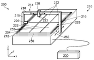
도 2는 본 발명에 따른 장치(200)의 개략적인 도시를 제공한다. 도시된 바와 같이, 도 1의 장치와 유사하게, 장치(200)는 기판, 예를 들어, 유리 FPD 시트(250)를 수용하여 처리하기 위한 기계(210)를 포함한다. 이해되는 바와 같이, FPD 시트(250)는 유리가 아닌 재료, 예를 들어 플라스틱으로 이루어질 수 있으며, 물론 복합 재료로 이루어질 수 있다. FPD 시트(250)는 FPD를 형성하기 위하여(그러나, 이해되는 바와 같이, 본 발명도 평판 디스플레이가 아닌 컴포넌트, 예를 들어 전자 회로 보드 및/또는 가요성 전자 회로의 제조에 사용하는데에도 적합하다) 각각이 기계(210)(그리고 많은 실시예에서 복수의 다른 기계)에 의해 처리되는 복수의 영역(252)을 포함한다. 이해되는 바와 같이, 처리는 하나 이상의 많은 상이한 작업을 포함할 수 있다. 예를 들어, FPD 시트(250)를 처리하는 단계는 다음을 포함할 수 있다: 하나 이상의 영역(252)에서 개별 셀/픽셀로 액정을 주입하는 단계; 하나 이상의 영역(252)을, 예를 들어 영역(252)의 적어도 일부에 대한 적어도 하나의 이미지를 획득하는 단계를 통해 불량/결함에 대하여 검사하는 단계; 및/또는 예를 들어 손상된 픽셀을 제거하기 위하여 레이저를 이용하여 영역(252)의 적어도 일부를 수리하는 단계. 기계(210)는, FPD 시트(250)가 로드되는 플랫폼(212)과, 제1 및 제2 직립 필라(116)와, 이들 사이에 연장되는 기판 처리부, 예를 들어 도구(222)(예를 들어, 레이저 또는 검사 카메라와 같은)가 로드되는 도구 홀더(220)를 운반하는 크로스 부재(218)를 포함하는 갠트리(214)를 포함한다. 종래 기술의 기계와 관련하여 전술한 바와 같이, 여러 도구가, 예를 들어 하나의 도구 홀더(120)를 통해 또는 여러 도구 홀더를 통해, 갠트리에 장착될 수 있다. 또한, 여러 갠트리가 하나의 기계에 제공될 수 있다. 제어 시스템(230)의 제어 하에서, 화살표 A로 나타낸 바와 같이, 갠트리(214)가 베어링과 모터(미도시)에 의해 y 차원에서 플랫폼(212)을 따라 이동될 수 있고, 화살표 B로 나타낸 바와 같이, 도구 홀더(220)가 베어링 및 모터(미도시)에 의해 x 차원에서 크로스 부재(218)를 따라 이동될 수 있다. 이해되는 바와 같이, 다른 실시예에서, 도구 홀더(120)는 크로스 부재(118)에 대하여 z 차원에서, 즉 플랫폼(112)으로부터 멀리 그리고 이를 향하여 수직으로 이동될 수 있다. 따라서, 도구(222)는 적어도 2개의 차원에서, 예를 들어 적어도 2개의 직교하는 차원에서, FPD 시트(250)에 대하여 이동될 수 있다.2 provides a schematic illustration of an
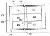
위치 측정 인코더가 기계(210)의 다양한 가동 부분(movable part)의 상대적 위치를 결정하기 위하여 제공된다. 예를 들어, 도시되지 않지만, 판독 헤드 및 스케일 배치가 도구 홀더(220) 및 크로스 부재(218)에 제공되어, x 차원에서의 이러한 상대적인 위치가 제어 시스템(230)으로 다시 보고될 수 있게 한다. 도 1에 도시된 실시예와는 다르게, y 차원에서 플랫폼(212)에 상대적인 갠트리(214)의 위치의 측정을 가능하기 하기 위한 플랫폼(212) 측에 장착된 스케일은 없다. 대신에, 도 2에(그리고 도 3에) 도시된 바와 같이, 제1 계측 스케일(254) 및 제2 계측 스케일(256)이 FPD 시트(250)의 대향하는 에지를 따라 제1 차원에서 연장되는 FPD 시트(250)의 상면에 제공된다. 제1 스케일(254) 및 제2 스케일(256)의 각각은 일련의 절대 위치 마킹을 포함한다. 설명된 실시예에서, 반드시 그럴 필요는 없지만, 제1 스케일(254)에서의 일련의 마킹은 제2 스케일(256)에서의 일련의 마킹에 일치한다.A positioning encoder is provided to determine the relative position of the various movable parts of the
또한, 도 2로부터 알 수 있는 바와 같이, FPD 시트(250)가 기계(210) 플랫폼(212)에 로드될 때 제1 판독 헤드(226)가 제1 스케일(254) 위로의 판독 위치에 위치되고 제2 판독 헤드(228)가 제2 스케일(256) 위로의 판독 위치에 위치되도록, 필라(216) 중 하나의 내부에 장착된 제1 판독 헤드(226)와 필라(216) 중 다른 하나의 내부에 장착된 제2 판독 헤드(228)가 제공된다. 따라서, 제1 판독 헤드(224)와 제2 판독 헤드(228)의 출력을 통하여 y 차원에서의 갠트리(214)(및 이에 따른 도구(222))와 FPD 시트(250)의 상대 위치가 결정되어 모니터될 수 있다.Also, as can be seen from FIG. 2, when the
제1 스케일(254) 및 제2 스케일(256)의 길이에 평행한 차원에서의(즉, 도 2에 도시된 설정에서는 y 차원에서의) FPD 시트(250)에 대한 도구(222)의 위치가 제1 스케일(254) 및 제2 스케일(256)의 길이에 평행한 차원에서의 FPD 영역(252) 어레이에 의해 정의된 전체 영역에 대하여 모니터될 수 있다. 이것은, 도시된 바와 같이, 제1 스케일(254) 및 제2 스케일(256)이 적어도 제1 스케일(254) 및 제2 스케일(256)의 길이에 평행한 차원에서 취해진 FPD 영역(252)(점선(258)으로 둘러싸인 영역에 의해 도시됨))에 의해 정의된 영역의 길이만큼 길기 때문이다. 사실, 설명되고 도시된 실시예에서, 제1 스케일(254) 및 제2 스케일(256)은 FPD 시트(250)의 전체 길이로 연장된다.Position of the
원한다면, 플랫폼(212)에 대한 갠트리(214)의 위치를 결정하기 위하여 추가 위치 측정 인코더가, 예를 들어, 갠트리(214)에 제공되어, 그 위치가 결정될 수 있다. 예를 들어, 도 1에 도시된 것과 유사하게 구성된 추가 판독 헤드 및 스케일이 제공될 수 있다. 이는 플랫폼(212) 상에 로드된 FPD 시트(250)가 없는 경우에도 플랫폼(212)에 대한 갠트리(214)의 위치가 결정될 수 있게 한다. 또한, 이는 갠트리(214)가 플랫폼(212)의 단부에 가까워지고 있는지 판단하는데 사용될 수 있다. 선택적으로, 이는 처리될 평판 디스플레이 영역의 부분으로 도구(222)를 구동하는데 사용될 수 있다. 그러나, 이러한 경우에서도, 처리되고 있는 평판 디스플레이 영역에 대한 도구(222)의 더 정확하고 반복 가능한 위치 설정을 제공할 수 있기 때문에, 도구(222)가 평판 디스플레이 영역을 처리할 수 있는 위치에 있는 적어도 일부 포인트에서, 제어 시스템(230)이 FPD 시트(250) 싱에서의 스케일(254, 256)을 판독하는 판독 헤드(226, 228)로부터의 판독값을 이용할 것이다. 예를 들어, 도구(222)가 촬상 유닛(imaging unit)이라면, FPD 시트(250)에서의 스케일(254, 256)로부터의 판독값은 이미지가 취해지는 도구(222) 및 FPD 시트(250)의 상대적인 위치에서 취해질 수 있어, 도구(222)와 FPD 시트의 상대적인 위치의 정확한 결정이 이루어질 수 있다. 다른 실시예에서, 예를 들어, 도구(222)가 적어도 하나의 평판 디스플레이 영역에 작용하여 추가 위치 측정 인코더로부터 판독하는 도구일 때, 도구(222)가 처리될 평판 디스플레이 영역의 근처로 이동될 때 도구(222)는 제어 시스템에 피드백을 제공하는데 사용될 수 있지만, 이것이 평판 디스플레이 영역에 작용할 수 있는 위치에 있을 때, 상대 위치에 대한 더 우수하고, 더 정확한 제어를 제공하기 위하여, 도구(222)와 FPD 시트(250)의 상대적 위치의 측정이 FPD 시트(250)에서 스케일(254, 256)로부터 취해져서 도구(222) 및 FPD 시트(250)의 상대적인 위치를 제어하는데 사용될 수 있다. 따라서, FPD 시트(250) 상의 스케일(254, 256) 자체가 정확한 상대적인 위치 설정을 보장하기 위하여 중요한 순간 동안에 사용됨에 따라, 이러한 추가 위치 측정 인코더는 도 1의 기계에서 제공된 것보다 훨씬 더 저렴하고 훨씬 더 하등(coarse)일 수 있다. 사실, 이러한 위치 측정은 y 차원에서 플랫폼에 대한 갠트리(214)의 이동에 영향을 미치는 모터(들) 상의 홀 센서(hall sensor)에 의해서도 제공될 수 있다.If desired, an additional position measuring encoder may be provided to the
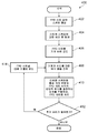
본 발명에 따른 FPD를 제조하는 예시적인 공정(400)에 포함된 단계들이 도 4에 도시된다. 방법(400)은 제1 스케일(254) 및 제2 스케일(256)이 FPD(250)에서 그 대향하는 에지를 따라 형성되는 단계 402(즉, 도 2 및 3에 도시된 바와 같이)에서 시작한다. 이것은 유리 기판 상에 스케일 마킹을 적용하기 위한 표준의 공지된 공정을 이용하여 유리 FPD 시트(250) 상에 표시될 수 있다. 예를 들어, 금속 재료(예를 들어, 크롬)이 FPD 시트에 부착되고, 이어 레지스트 재료층이 이를 덮는 포토리소그라피 공정이 사용될 수 있다. 그 다음, 레지스트 부분을 선택적으로 경화하는데 리소그라피가 사용될 수 있고, 이어 경화되지 않은 부분이 씻겨 없어진다. 그 다음, 에칭 공정이 노출된 크롬을 에칭하는데 사용될 수 있고, 에칭 단계 후에 남아 있는 레지스트가 제거된다. 남는 것은 (크롬이 에칭된) 저반사상 특징부와 에칭 단계 동안 레지스트에 의해 크롬이 덮인 (상대적인) 고반사성 특징부를 갖는 스케일이다. 이해되는 바와 같이, 많은 다른 기술이 FPD 시트 상에 스케일 마킹을 표시하는데 사용될 수 있다. 예를 들어, 국제 특허 출원 번호 PCT/GB03/00266(공보 번호 WO 03/061891)에 설명된 기술을 이용하는 것과 같이 레이저가 애블플레이션(ablation)을 통해 FPD 유리에 스케일 마킹을 형성하는데 사용될 수 있다. 다른 대체 방법이 FPD 시트(250) 상으로 재료, 예를 들어 반사성 잉크를 직접 인쇄하는 단계를 포함할 수 있다.The steps involved in an
제1 스케일(254) 및 제2 스케일(256)이 FPD 시트(250)로 표시되면, FPD 시트(250)는 시험 기계로 통과된다. (그러나. 이해되는 바와 같이, 스케일을 형성하기 위한 기계와 시험 기계는 동일한 기계일 수 있다. 사실, 동일한 기계가 FPD 기계를 처리하는데에도 사용될 수 있다.) 시험 기계는, FPD 시트(250)를 수용하기 위한 플랫폼과, 플랫폼 상에 로드된 FPD 시트에서 제1 스케일(254) 및 제2 스케일(256)을 판독하기 위하여 갠트리에서 도 2에 도시된 것과 유사하게 플랫폼을 따라 이동할 수 있는 제1 및 제2 판독 헤드를 가지는 점에서, 도 2에 도시된 것과 유사하다. 그러나, 이는 플랫폼에 대한 판독 헤드의 위치를 측정하기 위한 미리 캘리브레이션된 장치도 가진다. 예를 들어, 적어도 하나의 추가 판독 헤드 및 스케일 구성이 제공될 수 있다(예를 들어, 도 1에 도시된 것과 같이). 선택적으로, 플랫폼에 대한 제1(및 제2) 판독 헤드(들)의 움직임을 정확하게 추적하기 위한 레이저 간섭계 시스템이 제공될 수 있다. 플랫폼에 로드된 FPD 시트는 플랫폼에 대하여 고정 상태로 유지되고, FPD 시트에 대한 제1(및 제2) 판독 헤드(들)의 움직임이 제1 스케일(254) 및 제2 스케일(256)을 통해 측정된다. 제1 스케일(254)(및 제2 스케일(256))을 통해 획득된 측정값은 추가 측정 장치(예를 들어, 레이저 간섭계)에 의해 제공된 측정값에 비교된다. 양자 사이의 임의의 오차(에러)는 FPD 시트에 인쇄된 스케일에서의 오차에 기인하는 것으로 가정될 수 있으며, 따라서, FPD 시트에 대한 에러 맵 및/또는 에러 함수가 생성되어 아래에서 더욱 상세히 설명된 바와 같이 추후 사용을 위하여 저장될 수 있다. 예를 들어, 에러 맵 및/또는 에러 함수는 FPD 시트를 처리하는데 사용되는 기계들의 각각과 통신할 수 있는 중앙 서버 또는 데이터베이스에 저장될 수 있다If the
에러 맵 및/또는 에러 함수가 FPD 시트(250)에 대하여 생성된 후, 방법은 FPD 시트(250)가 기계(210) 상으로 로드되는 지점이 단계 406으로 진행한다. 이는 예를 들어 시험 기계로부터 FPD 시트(250)의 상승을 수동으로 제어하고, FPD 시트(250)를 처리하는 기계(210) 상에 배치하는 운전자를 통해 수동으로 수행될 수 있다. 선택적으로, 이는 자동으로 수행될 수 있다. 예를 들어, FPD 시트(250)는 FPD 시트(250)를 픽업하여 이동하고 배치하도록 구성된 로봇 아암과 같은 적합한 이송 기구를 통해 시험 기계로부터 FPD 시트(250)를 처리하기 위한 기계로 운송될 수 있다.After the error map and / or error function has been generated for the
단계 408에서, 기계(210)는 그 상에 로딩된 FPD 시트(250)에 대한 에러 맵 및/또는 에러 함수를 검색한다. (이해되는 바와 같이, 에러 맵 및/또는 에러 함수는 FPD 시트(250)가 기계 상에 로드되기 전에, 그 후에 또는 그 동안 검색될 수 있다.) 설명된 실시예에서, 에러 맵 및/또는 에러 함수는 기계가 처리하는 모든 FPD 시트에 대한 에러 맵 및/또는 에러 함수를 저장하는 중앙 서버로부터 검색된다. 물론, 다른 구현이 가능하다. 예를 들어, 기계(210)는 FPD 시트(250) 및 이것이 처리하는 임의의 다른 FPD 시트에 대한 에러 맵 및/또는 에러 함수를 자체 저장할 수 있다. 따라서, 기계(210)는 FPD 시트의 로드에 따라 자신의 로컬 메모리로부터 에러 맵 및/또는 에러 함수를 검색할 수 있다. FPD 시트(250)에 대한 에러 맵 및/또는 에러 함수는 기계에 대하여 이전에 생성된 임의의 에러 맵(들) 및/또는 에러 함수(들)과 결합될 수 있어, 이에 의해 기계 구성에 의해 그리고 FPD 시트(250)의 제1 스케일(254) 및 제2 스케일(256)에 의해 발생된 에러가 보상될 수 있게 한다.At
그 다음, 기계(210)는 단계 410에서 미리 결정된 루틴에 따라 FPD 시트(250)를 처리한다. 예를 들어, 기계는 액정을 하나 이상의 영역(252)에서의 개별 셀/픽셀로 주입하고, 예를 들어 영역(252)의 적어도 일부에 대한 적어도 하나의 이미지를 획득하는 단계를 통해, 하나 이상의 영역(252)을 불량/결함에 대하여 조사하고, 그리고/또는 손상된 픽셀을 제거하기 위하여 예를 들어 레이저를 이용하여 영역(252)의 적어도 일부를 수리하기 위하여 도구(222)를 이용할 수 있다. 이해되는 바와 같이, 이는 적합한 위치에 도구를 위치시키기 위한 FPD 시트(250)에 대한 도구(222)의 움직임을 포함할 수 있다. 처리 동작 동안, y 축에서의 FPD 시트(250)에 대한 도구(222)의 위치는 FPD 시트(250) 상에 인쇄된 제1 스케일(254) 및 제2 스케일(256)을 판독하는 제1 판독 헤드(226) 및 제2 판독 헤드(228)를 이용하여 모니터된다. 에러 맵 및/또는 에러 함수는 제1 판독 헤드(226) 및 제2 판독 헤드(228)를 통해 획득된 측정값을 교정하는데 사용된다. 위치가 FPD 시트(250) 자체에 직접 측정되기 때문에, FPD 시트(250)에 대한 도구(222)의 위치는, FPD 시트(250)가 플랫폼에 대하여 이동하고 그리고/또는 처리 동작 이전에 그리고/또는 그 동안 열 팽창/수축을 받더라도, y 차원에서 정확하게 알려진다. 또한, y 차원에서 플랫폼(212)에서 FPD 시트(250)의 바람직한 위치가 있을 수 있다. 바람직한 위치로부터의 FPD 시트(250)의 임의의 오프셋은 FPD 시트 자체에서 제1 스케일(254) 및 제2 스케일(256)로부터 결정될 수 있다. 또한, 기계 구성에 따라, 이는 기계 자체에서의 인코더/위치 센서로부터의 정보를 필요로 할 수 있다. 임의의 이러한 세로 방향 오프셋은 제1 스케일(254) 및 제2 스케일(256)을 이용하여 FPD 시트(250)를 바람직한 위치로 다시 이동시킴으로써 감소되거나 제거될 수 있고, 그리고/또는 오프셋은 제어 시스템(230)에 의해 자동으로 보상될 수 있다.The
기계(210) 상에서의 FPD 시트(250)의 처리가 완료되면, 단계 412에서 FPD 시트(250)가 후속 기계에서 더 많은 처리를 필요로 하는지 판단된다. 사실, FPD 시트(250)가 각각이 자신의 처리 작업(들)을 수행하도록 구성되는 도 2에 도시된 것과 유사한 많은 기계에 의해 처리될 필요가 있을 수 있다. 예를 들어, 하나의 기계가 영역(252)의 픽셀들로 액정을 추가하고, 다른 것이 영역(252)의 픽셀들을 검사하고, 다른 것이 영역(252)의 픽셀들을 수리하도록 구성될 수 있다. 이해되는 바와 같이, 이들은 단지 예이며, 수십 개의 많은 기계가 FPD 제조 라인에 있을 수 있다.Once the processing of the
처리가 후속 기계상에서 필요하다면, 단계 414에서, FPD 시트(250)는 (제1 기계(210) 상으로의 FPD 시트(250)의 로드와 관련하여 전술한 바와 같이 수동으로 또는 자동으로) 다음 기계로 로드된다. 그 다음, 이러한 후속 기계는 단계 408에서 에러 맵 및/또는 에러 함수를 (예를 들어, 중앙 서버로부터 또는 로컬 메모리 장치로부터) 검색하고 단계 410에서 자신의 전용 처리 동작에 따라 FPD 시트(250)를 처리한다. 전술한 것과 함께, 이는 후속 기계가 (에러 맵 및/또는 에러 함수를 이용하여 교정되는) 제1 판독 헤드(226) 및 제2 판독 헤드(228)의 출력을 통해 y 축에서 FPD 시트에 대한 갠트리 상의 임의의 이러한 도구의 위치를 결정하는 단계를 포함한다. 단계 408 내지 414는 FPD 시트(250)의 모든 처리가 제조 라인에서 마지막 기계에 의해 완료될 때까지 계속된다.If processing is needed on the subsequent machine, then at
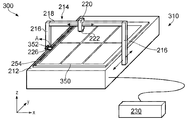
도 5는 도 2에 도시된 것에 유사한 본 발명의 대체 실시예를 도시하고, 유사한 부분은 유사한 도면 부호를 공유한다. 도 5에 도시된 실시예는, FPD 시트(350)가 자신의 에지 중 하나를 따라 제공된 하나의 스케일(254)만을 가진다는 점에서 도 2에 도시된 것과 다르다. 이해되는 바와 같이, y 차원에서 도구(222) 및 FPD 시트(350)의 상대적인 위치를 추적하기 위하여 단지 하나의 스케일만이 필요하다. 그럼에도 불구하고, 아래에서 더욱 상세히 설명되는 바와 같이, FPD 시트(250, 350)의 대향하는 에지의 각각에 하나씩 2개의 스케일의 제공은, 특히 시트가 플랫폼(212)에서 완벽하게 정렬되지 않을 때, 도구 및 FPD 시트의 상대적인 위치의 더욱 정확한 측정값을 제공하기 위하여 유용할 것이다. 또한, 도 5의 실시예는 스케일(254)를 판독하기 위한 판독 헤드(226)가 아암(352)을 통해 갠트리(214)의 직립 필라(216)에 장착된다는 점에서 상이하다. 아암(352)은, 판독 헤드(226)가 화살표 A로 도시된 방향으로 그 판독 위치로부터 멀리 스윙될 수 있도록, 피봇 조인트를 통해 직립 필라(216)에 장착된다. 판독 헤드(226)의 이러한 수축은 기계(310) 및 판독 헤드(226)의 유지 보수(예를 들어, 클리닝)뿐만 아니라 플랫폼(212) 상으로의 FPD 시트(250)의 로드/언로드를 도울 수 있다. 이해되는 바와 같이, 도 2의 실시예에서 도시된 판독 헤드(226, 228)의 하나 또는 양자가 이러한 수축 가능한 아암을 통해 갠트리(214)에 장착될 수 있다.FIG. 5 shows an alternative embodiment of the invention similar to that shown in FIG. 2, with like parts sharing like reference numerals. The embodiment shown in FIG. 5 differs from that shown in FIG. 2 in that the
도 6은 본 발명의 다른 실시예에 따른 FPD 시트(450)의 평면도를 도시한다. 도 2 및 3에 도시된 실시예와 유사하게, FPD 시트(450)는 복수의 FPD 영역(252)과, FPD 시트(450)의 대향하는 세로 방향 에지를 따라 연장되는 제1 스케일(254) 및 제2 스케일(256)을 포함한다. 그러나, 도 6에 도시된 FPD 시트(450)는 또한 자신의 단부들 중 하나에서 FPD 시트(450)의 폭에 걸쳐 부분적으로 제1 스케일(254) 및 제2 스케일(256)에 직교하여 연장되는 제3 스케일(452)을 포함한다. 이것은, 특히 기계의 플랫폼 상에 로드된 FPD 시트(450)의 측부 위치가 FPD 시트의 임의의 처리를 개시하기 이전에 결정되게 할 수 있도록, 갠트리, 특히 기계의 수직 필라(116)에 부착된 고정 아암에 장착된 판독 헤드에 의해 판독될 수 있다. 따라서, FPD 시트(450)의 임의의 측부 오프셋이 제3 스케일(452)를 이용하여 보상될 수 있다. 이해되는 바와 같이, 다른 실시예에서, 제3 스케일(452)에 대한 판독 헤드가 도구 홀더(120)에 또는 심지어 플랫폼(112) 상에 제공될 수 있다. 또한, 제3 스케일(452)은 더 큰 비율의 FPD 시트(250)의 폭, 예를 들어 FPD 시트(250)의 전체 폭에 걸쳐 연장될 수 있다. 또한, 제3 스케일(452)은 반드시 FPD 시트(250)의 단부에 배치될 필요가 없다. 예를 들어, 이는 FPD 시트(250)을 따라, 예를 들어, 영역(252)들 사이에서 중간에 배치될 수 있다. 또한, 동일한 것이 제1 스케일(254) 및 제2 스케일(256)에 적용되어, 예를 들어, 이들은 FPD 시트(250)의 에지에 배치될 필요가 없으며, 에지로부터 떨어져 예를 들어 영역(252)들 사이에 배치될 수 있다. 또 다른 실시예에서, x 및 y 차원 모두에서의 위치 정보를 제공하기 위하여 사용될 수 있는 2차원 스케일이 FPD 시트(250) 상에 형성될 수 있다. 예를 들어, 그리드형(grid-like) 스케일이 FPD 시트(250)의 하측에 제공되어, 예를 들어 플랫폼에서 FPD 시트(250)의 하부에 위치된 적어도 하나의 판독 헤드에 의해 판독될 수 있다. FPD 시트(250)로부터 제거될 수 있도록 2차원 스케일이 구성될 수 있고, 예를 들어, 스케일은 영역(252)이 화학품에 의해 처리된 후에 씻겨 없어질 수 있는 임시 스케일일 수 있다.6 shows a top view of an
도 7은 기계(210)의 플랫폼(212)에 로드된 도 2 및 3의 FPD 시트(250)의 평면도를 도시한다(간략함을 위하여, 갠트리(214)는 도 7에 도시되지 않지만, 제1 판독 헤드(226)와 제2 판독 헤드(228)가 도시된다). 도시된 바와 같이, 플랫폼의 평면에 수직인 축에 대하여 회전 방향으로 오프셋되는 방식으로 FPD 시트(250)가 플랫폼 상에 로드되었다. 그러나, FPD 시트(250)가 회전 방향으로 오프셋되고 회전 방향의 오프셋의 각도가 제1 판독 헤드(226) 및 제2 판독 헤드(228)에 의해 결정될 수 있다. 사실, 도 7에 도시된 바와 같이, 회전 방향 오프셋 때문에, 판독 헤드는 제1 스케일(254) 및 제2 스케일(256)의 길이를 따라 상이한 지점에 있을 것이고, 그 차이는 회전 방향 오프셋의 각도 θ(예를 들어, 도 7에 도시된 바와 같이 FPD 시트(250)의 세로 방향 측들 사이에 수직으로 연장되는 선(260)과 제1 판독 헤드(226) 및 제2 판독 헤드(228) 사이에 수직으로 연장되는 선(262) 사이의 각도)를 결정하는데 사용될 수 있다. 그 다음, FPD 시트(250)의 위치는 회전 방향 오프셋을 감소시키거나 제거하기 위하여 조정될 수 있으며, 그리고/또는 제어 시스템(230)은 처리 동작 동안 오프셋을 결정하여 판독하고, 임의의 위치 에러를 계산하고, 회전 방향 오프셋을 보상할 수 있다. 회전 방향 오프셋이 단지 제어 시스템(230)에 의해 보상되는지 또는 회전 방향 오프셋이 FPD 시트(250)을 이동시켜 감소될 수 있는지 여부는, 스케일을 측방향으로 진행하는 판독 헤드 없이 보상될 수 있는 최대 오프셋에 기초할 수 있다(이는 이어서 판독 헤드 윈도우의 크기 및 스케일의 폭에 의존할 수 있다).FIG. 7 shows a top view of the
도 8은 복수의 컴포넌트가 가요성 기판(300) 상에 제조되는 본 발명의 다른 대체적인 실시예를 도시하고, 각 컴포넌트는 기판 상에서 컴포넌트 영역(302) 내에 제조된다. 컴포넌트는 릴-투-릴(reel-to-reel) 처리 기계에서 제조되고, 따라서 전술한 다른 실시예에 도시된 바와 같이 플랫폼에 대향하여 기계 상에서 기판은 일련의 릴 또는 롤러(304)에 의해 지지되고 일련의 릴 또는 롤러(304)를 통해 이동된다. 또한, 릴-투-릴 처리 기계는, 릴-투-릴 공정에 따라 적어도 하나의 스테이지에서 (예를 들어, 검사를 통하거나 적어도 하나의 컴포넌트 영역에 작용함으로써) 적어도 하나의 부품 영역을 처리하기 위하여, 본 발명의 다른 실시예와 관련하여 전술한 것과 유사한 도구와 같은 기판 처리부(미도시)를 가진다. 다른 실시예와 관련하여 전술한 것과 실질적으로 동일한 계측 스케일(306)이 가요성 기판(300) 상에 제공되고 제1 차원에서 기판(300)의 길이를 따라 연장된다. 기판 처리부와 기판(300)의 상대적인 위치가 결정될 수 있게 하도록 계측 스케일(306)을 판독하는 기판 처리부와 관련된 판독 헤드(미도시)가 제공된다.8 illustrates another alternative embodiment of the present invention in which a plurality of components are fabricated on the
전술한 실시예에서, 제1 스케일(254) 및 제2 스케일(256)은 일련의 절대 위치를 정의하고, 예를 들어, US7499827 및 US5279044에 설명된 바와 같이, 절대 스케일로서 일반적으로 알려져 있다. 그러나, 이는 반드시 그럴 필요는 없다, 예를 들어, 제1 스케일(254) 및/또는 제2 스케일(256)은, 예를 들어, US4974962 및 US7659992에서 설명된 바와 같이, (기준 마크 위치를 가지거나 가지지 않는) 증분하는(incremental) 스케일을 포함할 수 있다.In the above embodiment, the
전술한 실시예들에서, 제1 스케일(254) 및 제2 스케일(256)은 연속하는 일련의 특징부에 의해 제공된다. 그러나, 이해되는 바와 같이, 이는 반드시 그럴 필요는 없다, 예를 들어, 제1 스케일(254) 및 제2 스케일(256)은 FPD 유리의 길이를 따라 이격된 일련의 개별 스케일 특징부 그룹에 의해 제공될 수 있다. 예를 들어, 제1 스케일(254) 및 제2 스케일(256)에서, 예를 들어 상이한 영역(252) 사이의 갭에서 갭이 있을 수 있다.In the above embodiments, the
전술한 실시예들에서, 스케일은 로드되는 기계에 의해 처리되는 FPD 시트(250) 측인 FPD 시트(250)의 상부측에 형성되었다. 그럼에도 불구하고, 스케일은 FPD 시트(250)의 하측에 형성될 수 있다. 이 경우에, 판독 헤드는 FPD 시트(250)를 통해 스케일을 판독하도록 구성될 수 있거나, 또는 FPD 시트(250)의 하부로부터 스케일을 판독하도록 위치될 수 있다. 다른 실시예에서, 스케일의 적어도 하나는 FPD 시트(250)의 수직 에지에, 즉 FPD 시트(250)의 림(rim)에 제공될 수 있다.In the above embodiments, the scale was formed on the top side of the
또한, 전술한 실시예들에서, 스케일은 FPD 시트(250)에 영구적으로 형성된다. 이는 영역(252)에 위치되지 않기 때문에, 영역(250)에 형성된 최종 제품과 간섭하지 않는다. 다른 실시예에서, 스케일은, 예를 들어, 비영구적 잉크를 이용하여 FPD 시트(250) 상에 스케일을 인쇄함으로써, FPD 시트(250)에 일시적으로 형성될 수 있다. 처리 후에, 스케일 마킹은 적합한 화학품을 이용하는 세정에 의해 제거될 수 있다. 이는 스케일이 영역(252) 그 자체를 포함하는 FPD 시트(250)에서의 어느 곳에서도 위치될 수 있게 한다.In addition, in the above embodiments, the scale is permanently formed in the
또한, 전술한 실시예들은 FPD 시트(250) 상에 제공된 복수의 영역(252)을 설명한다. 그러나, 이해되는 바와 같이, FPD 시트(250)에 제공된 하나의 영역과 같이 적을 수 있다.In addition, the embodiments described above describe a plurality of
또한, 전술한 실시예들은 기판(250, 300) 상에서의 모든 영역(252, 302)에 대하여 사용되는 제1 스케일(254, 306)(및 선택적으로는 제2 스케일(256))을 포함한다. 그러나, 이해되는 바와 같이, 상이한 영역(252, 302)에 대하여 개별 스케일이 제공될 수 있다. 예를 들어, 각각의 영역(252, 302)에 대하여 하나의 개별 스케일이 제공될 수 있다. 선택적으로, 제1 영역 그룹에 대한 적어도 하나의 스케일과 제2 영역 그룹에 대한 적어도 하나의 다른 스케일이 제공될 수 있다.In addition, the embodiments described above include
Claims (24)
적어도, 상기 기판 처리부와 상기 기판이, 상기 기판 처리부가 상기 기판 상에 상기 적어도 하나의 컴포넌트 영역을 처리할 수 있는 위치 관계를 가질 때, 상기 기판에 의해 제공된 적어도 제1 계측 스케일을 판독함으로써, 상기 기판에 대한 상기 기판 처리부의 위치를 측정하는 단계를 포함하는, 제조 방법.A method of manufacturing at least one component in at least one component region on a substrate using a machine having a substrate processing portion relatively movable relative to the substrate, the method comprising:
At least, when the substrate processing unit and the substrate have a positional relationship in which the substrate processing unit can process the at least one component region on the substrate, by reading at least the first measurement scale provided by the substrate, Measuring the position of the substrate treatment relative to the substrate.
기판의 적어도 하나의 컴포넌트 영역을 처리하는 기판 처리부를 포함하는 기계로서, 상기 기판 처리부와 상기 기판은, 상기 기판 처리부가 상기 기판 상의 상기 적어도 하나의 부품을 처리할 수 있는 위치 관계로 이동될 수 있도록, 서로에 대하여 이동 가능한, 상기 기계;
상기 기판 처리부와 상기 기판이 이러한 위치 관계에 있을 때, 상기 기판에 의해 제공된 스케일을 판독할 수 있도록 구성된 적어도 하나의 위치 센서; 및
상기 적어도 하나의 위치 센서로부터 판독값을 수신하고 상기 기판 처리부와 상기 적어도 하나의 컴포넌트 영역의 상대적인 위치를 측정하도록 구성된 제어 시스템
을 포함하는, 제조 장치.A manufacturing apparatus for manufacturing at least one component on a substrate,
A machine comprising a substrate processing portion for processing at least one component region of a substrate, wherein the substrate processing portion and the substrate are moved such that the substrate processing portion can be moved in a positional relationship that can process the at least one component on the substrate. The machine movable relative to each other;
At least one position sensor configured to read the scale provided by the substrate when the substrate processing portion and the substrate are in this positional relationship; And
A control system configured to receive a reading from the at least one position sensor and to measure a relative position of the substrate processing portion and the at least one component region
A manufacturing apparatus comprising a.
상기 기판은 상기 기판을 따라 연장되는 일련의 위치 마킹을 포함하는 적어도 제1 계측 스케일을 갖고,
상기 적어도 제1 계측 스케일은, 상기 기판과, 상기 적어도 하나의 컴포넌트 영역의 적어도 하나를 처리하는데 사용되는 기계의 기판 처리부의 상대적인 위치를 모니터하는데 사용되는, 컴포넌트 제조 방법.Obtaining a substrate comprising at least one component region,
The substrate has at least a first metrology scale comprising a series of position markings extending along the substrate,
And the at least first metrology scale is used to monitor a relative position of the substrate and a substrate processing portion of a machine used to process at least one of the at least one component region.
처리를 위하여 적어도 하나의 기계 상으로 상기 기판을 로드하는 단계; 및
상기 기판의 스케일에 대한 상기 에러 맵 및/또는 에러 함수를 상기 적어도 하나의 기계에 공급하는 단계
를 포함하고,
상기 기계는 워크피스의 처리 동안 상기 기판의 스케일과 상기 에러 맵 및/또는 에러 함수를 이용하는, 제조 방법.Generating an error map and / or an error function for a metrology scale located on the substrate;
Loading the substrate onto at least one machine for processing; And
Supplying the error map and / or error function for the scale of the substrate to the at least one machine
Lt; / RTI >
The machine utilizes the scale of the substrate and the error map and / or error function during processing of a workpiece.
Applications Claiming Priority (3)
| Application Number | Priority Date | Filing Date | Title |
|---|---|---|---|
| EP11250638 | 2011-07-06 | ||
| EP11250638.1 | 2011-07-06 | ||
| PCT/GB2012/000569 WO2013004992A1 (en) | 2011-07-06 | 2012-07-05 | Method of manufacture and apparatus therefor |
Publications (1)
| Publication Number | Publication Date |
|---|---|
| KR20140039245A true KR20140039245A (en) | 2014-04-01 |
Family
ID=44511797
Family Applications (1)
| Application Number | Title | Priority Date | Filing Date |
|---|---|---|---|
| KR1020137035168A KR20140039245A (en) | 2011-07-06 | 2012-07-05 | Method of manufacture and apparatus therefor |
Country Status (7)
| Country | Link |
|---|---|
| US (1) | US20140123458A1 (en) |
| EP (1) | EP2729427A1 (en) |
| JP (1) | JP2014526140A (en) |
| KR (1) | KR20140039245A (en) |
| CN (1) | CN103619770A (en) |
| TW (1) | TWI502672B (en) |
| WO (1) | WO2013004992A1 (en) |
Cited By (1)
| Publication number | Priority date | Publication date | Assignee | Title |
|---|---|---|---|---|
| KR20160071788A (en) * | 2014-12-12 | 2016-06-22 | 주식회사 이오테크닉스 | Apparatus laser processing and method for driving the same |
Families Citing this family (15)
| Publication number | Priority date | Publication date | Assignee | Title |
|---|---|---|---|---|
| JP5920943B2 (en) * | 2013-04-18 | 2016-05-18 | エーピー システムズ インコーポレイテッド | Horizontal beam for cradle and substrate processing apparatus using the same |
| CN106488819B (en) | 2014-06-20 | 2018-06-22 | 维洛3D公司 | For the equipment, system and method for 3 D-printing |
| US10065270B2 (en) | 2015-11-06 | 2018-09-04 | Velo3D, Inc. | Three-dimensional printing in real time |
| US10071422B2 (en) | 2015-12-10 | 2018-09-11 | Velo3D, Inc. | Skillful three-dimensional printing |
| US20170239891A1 (en) | 2016-02-18 | 2017-08-24 | Velo3D, Inc. | Accurate three-dimensional printing |
| US11691343B2 (en) | 2016-06-29 | 2023-07-04 | Velo3D, Inc. | Three-dimensional printing and three-dimensional printers |
| US10286452B2 (en) | 2016-06-29 | 2019-05-14 | Velo3D, Inc. | Three-dimensional printing and three-dimensional printers |
| US20180126462A1 (en) | 2016-11-07 | 2018-05-10 | Velo3D, Inc. | Gas flow in three-dimensional printing |
| US10611092B2 (en) | 2017-01-05 | 2020-04-07 | Velo3D, Inc. | Optics in three-dimensional printing |
| US10369629B2 (en) | 2017-03-02 | 2019-08-06 | Veo3D, Inc. | Three-dimensional printing of three-dimensional objects |
| CN106938371A (en) * | 2017-03-16 | 2017-07-11 | 广东工业大学 | A kind of high-precision laser cutting machine and its crossbeam |
| US20180281283A1 (en) | 2017-03-28 | 2018-10-04 | Velo3D, Inc. | Material manipulation in three-dimensional printing |
| US10272525B1 (en) | 2017-12-27 | 2019-04-30 | Velo3D, Inc. | Three-dimensional printing systems and methods of their use |
| US10144176B1 (en) | 2018-01-15 | 2018-12-04 | Velo3D, Inc. | Three-dimensional printing systems and methods of their use |
| CN110508948A (en) * | 2018-05-22 | 2019-11-29 | 佛山市嘉实和生物科技有限公司 | A kind of multifunctional combination laser equipment |
Family Cites Families (16)
| Publication number | Priority date | Publication date | Assignee | Title |
|---|---|---|---|---|
| GB8616240D0 (en) | 1986-07-03 | 1986-08-13 | Renishaw Plc | Opto-electronic scale reading apparatus |
| JPH0360437A (en) * | 1989-07-26 | 1991-03-15 | Hitachi Ltd | Cutting mark |
| US5279044A (en) | 1991-03-12 | 1994-01-18 | U.S. Philips Corporation | Measuring device for determining an absolute position of a movable element and scale graduation element suitable for use in such a measuring device |
| JPH11281320A (en) * | 1998-03-30 | 1999-10-15 | Jasco Corp | Position sensing apparatus |
| GB0109057D0 (en) | 2001-04-11 | 2001-05-30 | Renishaw Plc | Absolute postition measurement |
| US20030104475A1 (en) | 2001-06-28 | 2003-06-05 | Kelly Scott D. | Method and apparatus for computer modeling of an adaptive immune response |
| JP4320560B2 (en) * | 2003-05-14 | 2009-08-26 | セイコーエプソン株式会社 | Droplet discharge device |
| JP2005326550A (en) * | 2004-05-13 | 2005-11-24 | Sanee Giken Kk | Exposure device |
| GB0413710D0 (en) | 2004-06-21 | 2004-07-21 | Renishaw Plc | Scale reading apparatus |
| US7375795B2 (en) * | 2004-12-22 | 2008-05-20 | Asml Netherlands B.V. | Lithographic apparatus, device manufacturing method, and device manufactured thereby |
| JP2007012426A (en) * | 2005-06-30 | 2007-01-18 | Optrex Corp | Organic el display panel, its manufacturing and inspection methods |
| TWI310326B (en) * | 2005-10-11 | 2009-06-01 | Gsi Group Corp | Optical metrological scale and laser-based manufacturing method therefor |
| GB2438600B (en) * | 2006-05-19 | 2008-07-09 | Exitech Ltd | Method for patterning thin films on moving substrates |
| KR20180085820A (en) | 2006-09-01 | 2018-07-27 | 가부시키가이샤 니콘 | Mobile object driving method, mobile object driving system, pattern forming method and apparatus, exposure method and apparatus, device manufacturing method and calibration method |
| US7812964B2 (en) * | 2006-11-15 | 2010-10-12 | Zygo Corporation | Distance measuring interferometer and encoder metrology systems for use in lithography tools |
| US8294878B2 (en) * | 2009-06-19 | 2012-10-23 | Nikon Corporation | Exposure apparatus and device manufacturing method |
-
2012
- 2012-07-05 US US14/127,104 patent/US20140123458A1/en not_active Abandoned
- 2012-07-05 WO PCT/GB2012/000569 patent/WO2013004992A1/en active Application Filing
- 2012-07-05 EP EP12737851.1A patent/EP2729427A1/en not_active Withdrawn
- 2012-07-05 KR KR1020137035168A patent/KR20140039245A/en not_active Application Discontinuation
- 2012-07-05 JP JP2014517910A patent/JP2014526140A/en active Pending
- 2012-07-05 CN CN201280031693.XA patent/CN103619770A/en active Pending
- 2012-07-06 TW TW101124511A patent/TWI502672B/en not_active IP Right Cessation
Cited By (1)
| Publication number | Priority date | Publication date | Assignee | Title |
|---|---|---|---|---|
| KR20160071788A (en) * | 2014-12-12 | 2016-06-22 | 주식회사 이오테크닉스 | Apparatus laser processing and method for driving the same |
Also Published As
| Publication number | Publication date |
|---|---|
| TW201312685A (en) | 2013-03-16 |
| US20140123458A1 (en) | 2014-05-08 |
| EP2729427A1 (en) | 2014-05-14 |
| JP2014526140A (en) | 2014-10-02 |
| TWI502672B (en) | 2015-10-01 |
| CN103619770A (en) | 2014-03-05 |
| WO2013004992A1 (en) | 2013-01-10 |
Similar Documents
| Publication | Publication Date | Title |
|---|---|---|
| TWI502672B (en) | Method for manufacturing electronic or non-electronic comoponents, apparatus therefor, and substrate for manufacturing electronic or non-electronic components | |
| TWI641302B (en) | Method and apparatus for automatically adjusting dispensing units of a dispenser | |
| TWI645267B (en) | Optical measuring device and method | |
| TWI610341B (en) | Imprint apparatus, imprint system, and method of manufacturing article | |
| JP5563319B2 (en) | Imprint apparatus and article manufacturing method | |
| JP2013505592A (en) | Device for aligning two substrates | |
| JP2006346593A (en) | Paste applying apparatus | |
| KR100685216B1 (en) | Substrate processing apparatus and substrate processing method | |
| US10921719B2 (en) | Optical measurement device and method | |
| JP6457773B2 (en) | Imprint method, imprint apparatus and article manufacturing method | |
| JP2016205957A (en) | Method for correcting movable head position of x-y substrate inspection device, and x-y substrate inspection device | |
| US11784077B2 (en) | Wafer overlay marks, overlay measurement systems, and related methods | |
| JP5930699B2 (en) | Imprint apparatus, imprint method, and device manufacturing method | |
| JP2013131577A5 (en) | ||
| EP3680105B1 (en) | Screen printing machine | |
| KR101387312B1 (en) | Proximity exposure apparatus, method for determining a substrate position in the proximity exposure apparatus and method of manufacturing a display panel substrate | |
| JP2016205958A (en) | Method for correcting movable head position of x-y substrate inspection device, and x-y substrate inspection device | |
| JP2560462B2 (en) | Film thickness measuring device | |
| JP2021531964A (en) | Systems and methods to transition from synchronous supply to asynchronous supply | |
| JP4627938B2 (en) | Square glass plate shape measuring device | |
| JP6639082B2 (en) | Lithographic apparatus, lithographic method, and article manufacturing method | |
| JP7070712B2 (en) | How to correct the detected value of the linear scale | |
| JP5884273B2 (en) | Exposure unit and substrate pre-alignment method | |
| JP2009054962A (en) | Positioning detector | |
| JP2008076738A (en) | Exposure apparatus |
Legal Events
| Date | Code | Title | Description |
|---|---|---|---|
| WITN | Application deemed withdrawn, e.g. because no request for examination was filed or no examination fee was paid |