JP2014210041A - 撮像装置および電子内視鏡 - Google Patents
撮像装置および電子内視鏡 Download PDFInfo
- Publication number
- JP2014210041A JP2014210041A JP2013087584A JP2013087584A JP2014210041A JP 2014210041 A JP2014210041 A JP 2014210041A JP 2013087584 A JP2013087584 A JP 2013087584A JP 2013087584 A JP2013087584 A JP 2013087584A JP 2014210041 A JP2014210041 A JP 2014210041A
- Authority
- JP
- Japan
- Prior art keywords
- cable
- imaging device
- image
- circuit board
- synchronization signal
- Prior art date
- Legal status (The legal status is an assumption and is not a legal conclusion. Google has not performed a legal analysis and makes no representation as to the accuracy of the status listed.)
- Granted
Links
- 238000003384 imaging method Methods 0.000 title claims abstract description 77
- 238000003780 insertion Methods 0.000 claims abstract description 23
- 230000037431 insertion Effects 0.000 claims abstract description 23
- 230000003287 optical effect Effects 0.000 claims description 8
- 238000010030 laminating Methods 0.000 claims 1
- 239000000758 substrate Substances 0.000 abstract description 24
- 239000007787 solid Substances 0.000 abstract 2
- 239000012491 analyte Substances 0.000 abstract 1
- 238000005452 bending Methods 0.000 description 18
- 230000004048 modification Effects 0.000 description 7
- 238000012986 modification Methods 0.000 description 7
- 230000002093 peripheral effect Effects 0.000 description 6
- 239000011521 glass Substances 0.000 description 5
- 238000005286 illumination Methods 0.000 description 5
- 239000011347 resin Substances 0.000 description 5
- 229920005989 resin Polymers 0.000 description 5
- 238000007789 sealing Methods 0.000 description 5
- 239000000470 constituent Substances 0.000 description 3
- 238000005476 soldering Methods 0.000 description 3
- 230000000694 effects Effects 0.000 description 2
- 239000000463 material Substances 0.000 description 2
- 239000004593 Epoxy Substances 0.000 description 1
- 239000000919 ceramic Substances 0.000 description 1
- 239000004020 conductor Substances 0.000 description 1
- 238000007689 inspection Methods 0.000 description 1
- 238000000034 method Methods 0.000 description 1
- 239000013307 optical fiber Substances 0.000 description 1
- 238000005549 size reduction Methods 0.000 description 1
- 230000001360 synchronised effect Effects 0.000 description 1
Images


Classifications
-
- A—HUMAN NECESSITIES
- A61—MEDICAL OR VETERINARY SCIENCE; HYGIENE
- A61B—DIAGNOSIS; SURGERY; IDENTIFICATION
- A61B1/00—Instruments for performing medical examinations of the interior of cavities or tubes of the body by visual or photographical inspection, e.g. endoscopes; Illuminating arrangements therefor
- A61B1/04—Instruments for performing medical examinations of the interior of cavities or tubes of the body by visual or photographical inspection, e.g. endoscopes; Illuminating arrangements therefor combined with photographic or television appliances
-
- G—PHYSICS
- G02—OPTICS
- G02B—OPTICAL ELEMENTS, SYSTEMS OR APPARATUS
- G02B23/00—Telescopes, e.g. binoculars; Periscopes; Instruments for viewing the inside of hollow bodies; Viewfinders; Optical aiming or sighting devices
- G02B23/24—Instruments or systems for viewing the inside of hollow bodies, e.g. fibrescopes
- G02B23/26—Instruments or systems for viewing the inside of hollow bodies, e.g. fibrescopes using light guides
Abstract
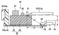
【解決手段】 撮像装置40は、被検体像を検出する受光素子部44aを備えた固体撮像素子44と、固体撮像素子44の駆動回路を構成する電子部品47,48が実装され、段差が設けられた回路基板部45,46と、回路基板部45,46に設けられたケーブル接続ランドと接続される複数のケーブル51,52,53,54,55と、を備え、複数のケーブル51,52,53,54,55のうち、画像信号を伝送する画像ケーブル51および同期信号を伝送する同期信号ケーブル53は、段差により離間する回路基板部45,46の異なる表面に接続されている。
【選択図】図4
Description
図2に示すように、内視鏡2の挿入部4の先端部31内には、撮像装置40が設けられ、この撮像装置40を嵌合保持する略円柱状の先端部本体41を備えている。この先端部本体41の基端外周部には、先端部31に撮像装置を収容する内部空間を形成する硬質管42が嵌合されている。
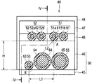
図3に示すように、対を成す画像信号ケーブル51a,51bからなる画像ケーブル51および対を成す制御信号ケーブル52a,52bからなるその他の制御ケーブル52は、リジット基板46の幅方向に並設され、それらの外皮が剥ぎ取られたそれぞれのケーブル芯線61,62がリジット基板46の表面上に設けられた複数のケーブル接続ランド(不図示)と半田付けにより接続される。
なお、図6および図7に示すように、リジット基板46の幅方向の寸法を小さくして、このリジット基板46の側面からFPC45に空いた領域を設け、この領域上に電子部品49を実装したり、同期信号ケーブル53を接続したりしてもよい。
2…電子内視鏡
3…周辺装置
4…挿入部
5…操作部
6…ユニバーサルコード
7…内視鏡コネクタ
8…架台
9…光源装置
10…ビデオプロセッサ
11…接続ケーブル
12…キーボード
13…モニタ
14…湾曲操作ノブ
15,16…ボタン類
17…処置具挿入口
18…固定用レバー
21…上下湾曲操作用ノブ
22…左右湾曲操作用ノブ
31…先端部
32…湾曲部
33…可撓管部
40…撮像装置
41…先端部本体
42…硬質管
43…レンズユニット
43a…対物レンズ
43b…レンズホルダ
44…固体撮像素子
44a…受光素子部
45…フレキシブルプリント基板
45a…封止樹脂
46…リジット基板
47,48…電子部品
49…ガラスリッド
50…回路基板部
51…画像ケーブル
51a,51b…画像信号ケーブル
52…制御ケーブル
52a,52b…制御信号ケーブル
53…同期信号ケーブル
54…電源ケーブル
55…グランドケーブル
61,62,63,64,65…ケーブル芯線
O…撮影光軸
Claims (9)
- 被検体像を検出する受光素子部を備えた固体撮像素子と、
前記固体撮像素子の駆動回路を構成する電子部品が実装され、段差が設けられた回路基板部と、
前記回路基板部に設けられたケーブル接続ランドと接続される複数のケーブルと、
を備え、
前記複数のケーブルのうち、画像信号を伝送する画像ケーブルおよび同期信号を伝送する同期信号ケーブルは、前記段差により離間する前記回路基板部の異なる表面に接続されていることを特徴とする撮像装置。 - 前記回路基板部は、フレキシブルプリント基板上にリジッド基板が積層接続されて形成され、前記フレキシブルプリント基板の表面および前記リジット基板の表面によって高さ方向に離間する前記段差が形成され、
前記画像ケーブルおよび前記同期信号ケーブルは、前記回路基板部の前記高さ方向に互いが離間する位置に接続されていることを特徴とする請求項1に記載の撮像装置。 - 前記画像ケーブルおよび前記同期信号ケーブルは、前記回路基板部の前記被検体像の撮影光軸に沿った長手方向に互いが離間する位置に接続されていることを特徴とする請求項1または請求項2に記載の撮像装置。
- 前記画像ケーブルおよび前記同期信号ケーブルは、前記回路基板部の幅方向に離間する位置に接続されていることを特徴とする請求項1から請求項3のいずれか1項に記載の撮像装置。
- 前記画像ケーブルおよび前記同期信号ケーブルは、前記回路基板部の前記被検体像の撮影光軸に沿った長手方向に直交する断面における対角方向に離間する位置に接続されていることを特徴とする請求項1から請求項4のいずれか1項に記載の撮像装置。
- 前記リジッド基板、前記電子部品および前記複数のケーブルは、前記被検体像の撮影光軸に沿った固体撮像素子の投影面積内に収容されていることを特徴とする請求項1から請求項5のいずれか1項に記載の撮像装置。
- 前記複数のケーブルのうち、電源ケーブルおよび/またはグランドケーブルが前記段差の前記高さ方向における下段側に接続されていることを特徴とする請求項2から請求項5のいずれか1項に記載の撮像装置。
- 前記段差は、0.2mm〜4.00mmの範囲内であることを特徴とする請求項1から請求項7のいずれか1項に記載の撮像装置。
- 請求項1から請求項7のいずれか1項に記載の撮像装置が挿入部の先端部に設けられたことを特徴とする電子内視鏡。
Priority Applications (5)
| Application Number | Priority Date | Filing Date | Title |
|---|---|---|---|
| JP2013087584A JP6321917B2 (ja) | 2013-04-18 | 2013-04-18 | 撮像装置および電子内視鏡 |
| CN201480021722.3A CN105208908A (zh) | 2013-04-18 | 2014-04-16 | 摄像装置和电子内窥镜 |
| PCT/JP2014/060818 WO2014171482A1 (ja) | 2013-04-18 | 2014-04-16 | 撮像装置および電子内視鏡 |
| EP14784990.5A EP2987448A4 (en) | 2013-04-18 | 2014-04-16 | IMAGING DEVICE AND ELECTRONIC ENDOSCOPE |
| US14/885,291 US20160037029A1 (en) | 2013-04-18 | 2015-10-16 | Image pickup apparatus and electronic endoscope |
Applications Claiming Priority (1)
| Application Number | Priority Date | Filing Date | Title |
|---|---|---|---|
| JP2013087584A JP6321917B2 (ja) | 2013-04-18 | 2013-04-18 | 撮像装置および電子内視鏡 |
Publications (2)
| Publication Number | Publication Date |
|---|---|
| JP2014210041A true JP2014210041A (ja) | 2014-11-13 |
| JP6321917B2 JP6321917B2 (ja) | 2018-05-09 |
Family
ID=51930297
Family Applications (1)
| Application Number | Title | Priority Date | Filing Date |
|---|---|---|---|
| JP2013087584A Active JP6321917B2 (ja) | 2013-04-18 | 2013-04-18 | 撮像装置および電子内視鏡 |
Country Status (1)
| Country | Link |
|---|---|
| JP (1) | JP6321917B2 (ja) |
Cited By (2)
| Publication number | Priority date | Publication date | Assignee | Title |
|---|---|---|---|---|
| WO2017158722A1 (ja) * | 2016-03-15 | 2017-09-21 | オリンパス株式会社 | 撮像装置、内視鏡、及び、撮像装置の製造方法 |
| CN113196738A (zh) * | 2018-12-19 | 2021-07-30 | Lg伊诺特有限公司 | 摄像头模块 |
Citations (3)
| Publication number | Priority date | Publication date | Assignee | Title |
|---|---|---|---|---|
| JP2003010111A (ja) * | 2001-06-27 | 2003-01-14 | Olympus Optical Co Ltd | 撮像装置 |
| JP2011050497A (ja) * | 2009-08-31 | 2011-03-17 | Olympus Medical Systems Corp | 撮像装置及び電子内視鏡 |
| JP2012183330A (ja) * | 2012-05-14 | 2012-09-27 | Olympus Medical Systems Corp | 撮像装置 |
-
2013
- 2013-04-18 JP JP2013087584A patent/JP6321917B2/ja active Active
Patent Citations (3)
| Publication number | Priority date | Publication date | Assignee | Title |
|---|---|---|---|---|
| JP2003010111A (ja) * | 2001-06-27 | 2003-01-14 | Olympus Optical Co Ltd | 撮像装置 |
| JP2011050497A (ja) * | 2009-08-31 | 2011-03-17 | Olympus Medical Systems Corp | 撮像装置及び電子内視鏡 |
| JP2012183330A (ja) * | 2012-05-14 | 2012-09-27 | Olympus Medical Systems Corp | 撮像装置 |
Cited By (5)
| Publication number | Priority date | Publication date | Assignee | Title |
|---|---|---|---|---|
| WO2017158722A1 (ja) * | 2016-03-15 | 2017-09-21 | オリンパス株式会社 | 撮像装置、内視鏡、及び、撮像装置の製造方法 |
| US11134829B2 (en) | 2016-03-15 | 2021-10-05 | Olympus Corporation | Image pickup apparatus, endoscope, and method for manufacturing image pickup apparatus |
| CN113196738A (zh) * | 2018-12-19 | 2021-07-30 | Lg伊诺特有限公司 | 摄像头模块 |
| CN113196738B (zh) * | 2018-12-19 | 2023-09-29 | Lg伊诺特有限公司 | 摄像头模块 |
| US11863850B2 (en) | 2018-12-19 | 2024-01-02 | Lg Innotek Co., Ltd. | Camera module |
Also Published As
| Publication number | Publication date |
|---|---|
| JP6321917B2 (ja) | 2018-05-09 |
Similar Documents
| Publication | Publication Date | Title |
|---|---|---|
| WO2014171482A1 (ja) | 撮像装置および電子内視鏡 | |
| CN107149460B (zh) | 内窥镜 | |
| CN106886089B (zh) | 内窥镜 | |
| EP3050491B1 (en) | Endoscope device | |
| US20180070803A1 (en) | Imaging device and endoscope system | |
| WO2016063603A1 (ja) | 固体撮像装置およびこの固体撮像装置を備えた電子内視鏡 | |
| JP5977892B1 (ja) | 撮像ユニットおよびこの撮像ユニットを備えた電子内視鏡 | |
| JP2011212161A (ja) | 固体撮像装置及び内視鏡装置 | |
| WO2015045630A1 (ja) | 撮像モジュールおよび内視鏡装置 | |
| WO2019044609A1 (ja) | 内視鏡 | |
| JP6650378B2 (ja) | 内視鏡 | |
| JP6205228B2 (ja) | 撮像モジュールおよび内視鏡装置 | |
| WO2017130371A1 (ja) | 撮像装置および内視鏡 | |
| US10517465B2 (en) | Cable connection structure and endoscope apparatus | |
| JP6321917B2 (ja) | 撮像装置および電子内視鏡 | |
| CN107115088B (zh) | 内窥镜 | |
| JP2016214660A (ja) | 医療用カメラヘッド及び医療用カメラ装置 | |
| JP2015080675A (ja) | 内視鏡及び内視鏡の製造方法 | |
| JP6321916B2 (ja) | 撮像装置および電子内視鏡 | |
| JP2018007715A (ja) | 内視鏡 | |
| JP6081347B2 (ja) | 撮像ユニットおよび内視鏡 | |
| JP7029296B2 (ja) | 内視鏡の基板ユニット | |
| JP6223092B2 (ja) | 内視鏡装置 | |
| WO2017115441A1 (ja) | 実装構造体、撮像装置および内視鏡 | |
| JP2015080633A (ja) | 電気ユニット及び電気ユニットを用いた内視鏡装置 |
Legal Events
| Date | Code | Title | Description |
|---|---|---|---|
| A621 | Written request for application examination |
Free format text: JAPANESE INTERMEDIATE CODE: A621 Effective date: 20160325 |
|
| A131 | Notification of reasons for refusal |
Free format text: JAPANESE INTERMEDIATE CODE: A131 Effective date: 20161108 |
|
| A601 | Written request for extension of time |
Free format text: JAPANESE INTERMEDIATE CODE: A601 Effective date: 20161118 |
|
| A521 | Request for written amendment filed |
Free format text: JAPANESE INTERMEDIATE CODE: A523 Effective date: 20170302 |
|
| A131 | Notification of reasons for refusal |
Free format text: JAPANESE INTERMEDIATE CODE: A131 Effective date: 20170711 |
|
| A601 | Written request for extension of time |
Free format text: JAPANESE INTERMEDIATE CODE: A601 Effective date: 20170901 |
|
| A521 | Request for written amendment filed |
Free format text: JAPANESE INTERMEDIATE CODE: A523 Effective date: 20171106 |
|
| TRDD | Decision of grant or rejection written | ||
| A01 | Written decision to grant a patent or to grant a registration (utility model) |
Free format text: JAPANESE INTERMEDIATE CODE: A01 Effective date: 20180313 |
|
| A61 | First payment of annual fees (during grant procedure) |
Free format text: JAPANESE INTERMEDIATE CODE: A61 Effective date: 20180406 |
|
| R150 | Certificate of patent or registration of utility model |
Ref document number: 6321917 Country of ref document: JP Free format text: JAPANESE INTERMEDIATE CODE: R150 |
|
| R250 | Receipt of annual fees |
Free format text: JAPANESE INTERMEDIATE CODE: R250 |
|
| R250 | Receipt of annual fees |
Free format text: JAPANESE INTERMEDIATE CODE: R250 |
|
| R250 | Receipt of annual fees |
Free format text: JAPANESE INTERMEDIATE CODE: R250 |
|
| R250 | Receipt of annual fees |
Free format text: JAPANESE INTERMEDIATE CODE: R250 |