JP2014210041A - Imaging device and electronic endoscope - Google Patents
Imaging device and electronic endoscope Download PDFInfo
- Publication number
- JP2014210041A JP2014210041A JP2013087584A JP2013087584A JP2014210041A JP 2014210041 A JP2014210041 A JP 2014210041A JP 2013087584 A JP2013087584 A JP 2013087584A JP 2013087584 A JP2013087584 A JP 2013087584A JP 2014210041 A JP2014210041 A JP 2014210041A
- Authority
- JP
- Japan
- Prior art keywords
- cable
- imaging device
- image
- circuit board
- synchronization signal
- Prior art date
- Legal status (The legal status is an assumption and is not a legal conclusion. Google has not performed a legal analysis and makes no representation as to the accuracy of the status listed.)
- Granted
Links
- 238000003384 imaging method Methods 0.000 title claims abstract description 77
- 238000003780 insertion Methods 0.000 claims abstract description 23
- 230000037431 insertion Effects 0.000 claims abstract description 23
- 230000003287 optical effect Effects 0.000 claims description 8
- 238000010030 laminating Methods 0.000 claims 1
- 239000000758 substrate Substances 0.000 abstract description 24
- 239000007787 solid Substances 0.000 abstract 2
- 239000012491 analyte Substances 0.000 abstract 1
- 238000005452 bending Methods 0.000 description 18
- 230000004048 modification Effects 0.000 description 7
- 238000012986 modification Methods 0.000 description 7
- 230000002093 peripheral effect Effects 0.000 description 6
- 239000011521 glass Substances 0.000 description 5
- 238000005286 illumination Methods 0.000 description 5
- 239000011347 resin Substances 0.000 description 5
- 229920005989 resin Polymers 0.000 description 5
- 238000007789 sealing Methods 0.000 description 5
- 239000000470 constituent Substances 0.000 description 3
- 238000005476 soldering Methods 0.000 description 3
- 230000000694 effects Effects 0.000 description 2
- 239000000463 material Substances 0.000 description 2
- 239000004593 Epoxy Substances 0.000 description 1
- 239000000919 ceramic Substances 0.000 description 1
- 239000004020 conductor Substances 0.000 description 1
- 238000007689 inspection Methods 0.000 description 1
- 238000000034 method Methods 0.000 description 1
- 239000013307 optical fiber Substances 0.000 description 1
- 238000005549 size reduction Methods 0.000 description 1
- 230000001360 synchronised effect Effects 0.000 description 1
Images


Classifications
-
- A—HUMAN NECESSITIES
- A61—MEDICAL OR VETERINARY SCIENCE; HYGIENE
- A61B—DIAGNOSIS; SURGERY; IDENTIFICATION
- A61B1/00—Instruments for performing medical examinations of the interior of cavities or tubes of the body by visual or photographical inspection, e.g. endoscopes; Illuminating arrangements therefor
- A61B1/04—Instruments for performing medical examinations of the interior of cavities or tubes of the body by visual or photographical inspection, e.g. endoscopes; Illuminating arrangements therefor combined with photographic or television appliances
-
- G—PHYSICS
- G02—OPTICS
- G02B—OPTICAL ELEMENTS, SYSTEMS OR APPARATUS
- G02B23/00—Telescopes, e.g. binoculars; Periscopes; Instruments for viewing the inside of hollow bodies; Viewfinders; Optical aiming or sighting devices
- G02B23/24—Instruments or systems for viewing the inside of hollow bodies, e.g. fibrescopes
- G02B23/26—Instruments or systems for viewing the inside of hollow bodies, e.g. fibrescopes using light guides
Abstract
Description
本発明は、撮像装置およびこの撮像装置が設けられた電子内視鏡に関する。 The present invention relates to an imaging device and an electronic endoscope provided with the imaging device.
周知の如く、内視鏡は、生体の体内(体腔内)における医療用の観察、処置など、または工業用のプラント設備内の検査、修理などのため広く用いられている。特に、医療用の内視鏡は、細長の挿入部を体腔内に挿入することにより、切開を必要とすることなく、体腔内の検査対象部位を観察でき、必要に応じ、処置具を用いて治療処置できるため広く用いられるようになった。 As is well known, endoscopes are widely used for medical observation and treatment in the body of a living body (inside a body cavity) or for inspection and repair in industrial plant equipment. In particular, medical endoscopes can observe a region to be examined in a body cavity by inserting an elongated insertion portion into the body cavity without requiring an incision. Since it can be treated, it has become widely used.
このような内視鏡には、例えば、特許文献1に開示されるような、挿入部の先端部に撮像装置が配設されている電子内視鏡がある。この従来の電子内視鏡の撮像装置は、回路基板に接続されるケーブルが回路基板の同一面上にそれぞれが近接して形成されたケーブル接続用ランドに半田付けされている。 An example of such an endoscope is an electronic endoscope in which an imaging device is disposed at a distal end portion of an insertion portion as disclosed in Patent Document 1. In this conventional electronic endoscope imaging apparatus, cables connected to a circuit board are soldered to cable connection lands formed on the same surface of the circuit board close to each other.
しかしながら、特許文献1の電子内視鏡のように、回路基板上に画像信号ケーブルと同期信号ケーブルを隣接して配置させると、同期信号ケーブルから生じる電磁波が画像信号ケーブルによって伝送される画像信号に干渉してノイズが生じてしまう恐れがある。画像信号にノイズが生じると、モニタに表示させる内視鏡画像が乱れたりして安定しなくなってしまうという問題がある。 However, when the image signal cable and the synchronization signal cable are arranged adjacent to each other on the circuit board as in the electronic endoscope of Patent Document 1, the electromagnetic wave generated from the synchronization signal cable is converted into an image signal transmitted by the image signal cable. There is a risk of noise due to interference. When noise occurs in the image signal, there is a problem that the endoscope image displayed on the monitor is disturbed and becomes unstable.
なお、特許文献1に開示されるように、回路基板のケーブルランド上に中継部材を設けるなどして、各種信号ケーブルの接続部に高低差を設けたり、基板の表裏面にケーブル接続用ランドを設けたりすることで、ケーブル同士の距離を離すこともできるが、中継部材を取り付ける工程が増えることや、基板の表裏面にはんだ付けをする煩わしさが課題として残ってしまう。 In addition, as disclosed in Patent Document 1, a relay member is provided on the cable land of the circuit board so that a difference in height is provided in the connection portion of various signal cables, or cable connection lands are provided on the front and back surfaces of the board. Although it is possible to increase the distance between the cables by providing them, the process of attaching the relay member increases and the trouble of soldering on the front and back surfaces of the substrate remains as a problem.
さらに、回路基板に中継部材を設けることで、回路基板が大型となり、撮像装置の小型化に限界が生じてしまう。そのため、撮像装置が内蔵される電子内視鏡の挿入部の先端部の小型化にも限界があり、電子内視鏡の挿入部の細径化を阻害しているという問題があった。 Furthermore, by providing the relay member on the circuit board, the circuit board becomes large, and there is a limit to downsizing of the imaging device. For this reason, there is a limit to miniaturization of the distal end portion of the insertion portion of the electronic endoscope in which the imaging device is built in, and there has been a problem that the diameter reduction of the insertion portion of the electronic endoscope is hindered.
そこで、本発明は、上記事情に鑑みてなされたものであり、その目的とするところは簡便な構成で画像信号に発生するノイズを低減して安定した画像が得られる小型な撮像装置となり、挿入部の先端部の小型化を可能として挿入部を細径化できる電子内視鏡を提供することを目的としている。 Therefore, the present invention has been made in view of the above circumstances, and an object of the present invention is a compact imaging device that can obtain a stable image by reducing noise generated in an image signal with a simple configuration, and is inserted. An object of the present invention is to provide an electronic endoscope capable of reducing the diameter of the insertion portion by allowing the tip portion of the portion to be miniaturized.
本発明の一態様の撮像装置は、被検体像を検出する受光素子部を備えた固体撮像素子と、前記固体撮像素子の駆動回路を構成する電子部品が実装され、段差が設けられた回路基板部と、前記回路基板部に設けられたケーブル接続ランドと接続される複数のケーブルと、を備え、前記複数のケーブルのうち、画像信号を伝送する画像ケーブルおよび同期信号を伝送する同期信号ケーブルは、前記段差により離間する前記回路基板部の異なる表面に接続されている。 An imaging apparatus according to an aspect of the present invention is a circuit board on which a solid-state imaging device including a light-receiving element portion that detects a subject image and an electronic component that constitutes a driving circuit of the solid-state imaging device are mounted and provided with a step. And a plurality of cables connected to cable connection lands provided on the circuit board unit, and among the plurality of cables, an image cable that transmits an image signal and a synchronization signal cable that transmits a synchronization signal are And connected to different surfaces of the circuit board portion separated by the step.
本発明の一態様の内視鏡は、被検体像を検出する受光素子部を備えた固体撮像素子と、前記固体撮像素子の駆動回路を構成する電子部品が実装され、段差が設けられた回路基板部と、前記回路基板部に設けられたケーブル接続ランドと接続される複数のケーブルと、を備え、前記複数のケーブルのうち、画像信号を伝送する画像ケーブルおよび同期信号を伝送する同期信号ケーブルは、前記段差により離間する前記回路基板部の異なる表面に接続されている撮像装置が挿入部の先端部に設けられている。 An endoscope according to an aspect of the present invention is a circuit in which a solid-state imaging device including a light-receiving element portion that detects a subject image and an electronic component that configures a driving circuit of the solid-state imaging device are mounted, and a step is provided. A board part and a plurality of cables connected to a cable connection land provided on the circuit board part, and among the plurality of cables, an image cable for transmitting an image signal and a synchronization signal cable for transmitting a synchronization signal The image pickup device connected to different surfaces of the circuit board portion separated by the step is provided at the distal end portion of the insertion portion.
本発明によれば、簡便な構成で画像信号に発生するノイズを低減して安定した画像が得られる小型な撮像装置となり、挿入部の先端部の小型化を可能として挿入部を細径化できる電子内視鏡を提供することができる。 According to the present invention, it is possible to reduce the noise generated in the image signal with a simple configuration and obtain a stable image, and to reduce the diameter of the insertion portion by reducing the size of the distal end of the insertion portion. An electronic endoscope can be provided.
以下、図面を参照して、本実施の形態の内視鏡先端構造を備える内視鏡について説明する。図1は、本実施形態を示す内視鏡を具備する内視鏡装置の外観を示す斜視図、図2は先端部の内部構成を示す断面図、図3は撮像装置を後方から見た平面図、図4は図3のIV−IV線に沿った撮像装置の構成を示す断面図、図5は撮像装置の構成を示す上面図、図6は変形例の撮像装置を後方から見た平面図、図7は変形例の撮像装置の構成を示す側面図である。 Hereinafter, with reference to the drawings, an endoscope provided with the endoscope tip structure of the present embodiment will be described. FIG. 1 is a perspective view illustrating an external appearance of an endoscope apparatus including an endoscope according to the present embodiment, FIG. 2 is a cross-sectional view illustrating an internal configuration of a distal end portion, and FIG. 3 is a plan view of the imaging apparatus viewed from the rear. 4 is a cross-sectional view illustrating the configuration of the imaging device along the line IV-IV in FIG. 3, FIG. 5 is a top view illustrating the configuration of the imaging device, and FIG. 6 is a plan view of the imaging device according to the modification viewed from the rear. 7 and 7 are side views showing the configuration of an imaging apparatus according to a modification.
なお、以下の説明において、実施の形態に基づく図面は、模式的なものであり、各部分の厚みと幅との関係、夫々の部分の厚みの比率などは現実のものとは異なることに留意すべきであり、図面の相互間においても互いの寸法の関係や比率が異なる部分が含まれている場合がある。 In the following description, the drawings based on the embodiments are schematic, and the relationship between the thickness and width of each part, the ratio of the thickness of each part, and the like are different from the actual ones. There should be a case where parts having different dimensional relationships and ratios are included in the drawings.
図1に示すように、内視鏡装置1は、電子内視鏡(以下、単に内視鏡という)2および周辺装置3により主要部が構成されている。内視鏡2は、被検体内に挿入される挿入部4と、この挿入部4の基端側に接続された操作部5と、ユニバーサルコード6と、内視鏡コネクタ7とから主要部が構成されている。
As shown in FIG. 1, an endoscope apparatus 1 is mainly composed of an electronic endoscope (hereinafter simply referred to as an endoscope) 2 and a
周辺装置3は、光源装置9、ビデオプロセッサ10、接続ケーブル11、キーボード12、モニタ13などが架台8に載置されてシステムが構成されている。また、このような構成を有する内視鏡2および周辺装置3とは、内視鏡コネクタ7により互いに接続されている。
In the
内視鏡2の操作部5には、湾曲操作ノブ14と、内視鏡機能を操作するボタン類15,16と、処置具挿入口17と、操作部材である回動自在な固定用レバー18とが設けられている。なお、湾曲操作ノブ14は、上下湾曲操作用ノブ21と左右湾曲操作用ノブ22とから構成されている。
The operation section 5 of the
内視鏡2の挿入部4は、先端側から順に、先端部31と、この先端部31の基端側に連設された動作部である複数方向に湾曲自在な湾曲部32と、この湾曲部32の基端側に連設された可撓管部33と、により構成されている。
The insertion portion 4 of the
湾曲部32は、操作部5に設けられた湾曲操作ノブ14の2つ上下湾曲操作用ノブ21と左右湾曲操作用ノブ22による回動操作入力によって動作する。即ち、湾曲部32は、湾曲操作ノブ14の操作によって湾曲するものであり、挿入部4内に挿通された湾曲操作ワイヤ(不図示)の牽引弛緩に伴い、例えば上下左右の4方向に湾曲自在となっている。
The
内視鏡2のユニバーサルコード6の先端に設けられた内視鏡コネクタ7は、周辺装置3の光源装置9に接続されている。内視鏡コネクタ7には、図示しない各種口金や、各種電気接点が設けられているとともに、ビデオプロセッサ10と接続ケーブル11を介して電気的に接続されている。
An endoscope connector 7 provided at the distal end of the
内視鏡2には、光源装置9からの照明光を伝送するライトガイドバンドル(不図示)が配設され、このライトガイドバンドルによる照明光の出射端に照明レンズ(不図示)が配置されている。この照明レンズは、挿入部4の先端部31に設けられており、照明光が被検体に向けて照射される。
The
なお、上述した内視鏡装置1の構成はあくまでも一例であり、上述の構成に限定されない。 Note that the configuration of the endoscope apparatus 1 described above is merely an example, and is not limited to the configuration described above.
次に、本実施の形態の内視鏡2の先端部31の構成と、この先端部31に配設される撮像装置の構成について以下に詳しく説明する。
図2に示すように、内視鏡2の挿入部4の先端部31内には、撮像装置40が設けられ、この撮像装置40を嵌合保持する略円柱状の先端部本体41を備えている。この先端部本体41の基端外周部には、先端部31に撮像装置を収容する内部空間を形成する硬質管42が嵌合されている。
Next, the configuration of the
As shown in FIG. 2, an
撮像装置40は、レンズユニット43、固体撮像素子44、FPC(フレキシブルプリント基板)45および回路基板としてのリジット基板46を主に有している。なお、リジット基板46およびFPC45には、複数の各種ケーブル51,52,53、電源ケーブル54またはグランド(GND)ケーブル55が接続されている(図3参照)。
The
レンズユニット43は、対物光学系である複数の対物レンズ43aを保持するレンズホルダ43bを備えており、このレンズホルダ43bが先端部本体41に挿嵌固定される。これにより、レンズユニット43が先端部本体41に固定される。
The
固体撮像素子44は、CCD、CMOSなどであって、レンズユニット43の複数の対物レンズによって集束された被検体像(図中の撮影光軸Oで示す撮影光)を検出する画素部としての受光素子部44aを備えている。そして、固体撮像素子44は、受光素子部44aを覆うようにガラスリッド49が貼着されている。
The solid-
ガラスリッド49は、前面がレンズユニット43の最基端の対物レンズ43aと固着されている。即ち、レンズユニット43と固体撮像素子44は、ガラスリッド49を介して固着されている。
The front surface of the
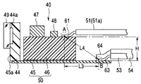
固体撮像素子44は、その表面下部の電極(不図示)に、FPC45のフライングリード(不図示)が電気的に接続され、封止樹脂45aにより封止されている。この封止樹脂45aは、FPC45の先端にて略90°折り曲げられているフライングリードを覆い、封止している。
The solid-
FPC45は、固体撮像素子44から後方側に延設されている。このFPC45の前方側の上部側の表面には、リジット基板46が電気的および機械的に積層するように接続されている。
The FPC 45 extends rearward from the solid-
これらFPC45およびリジット基板46によって撮像装置40の回路基板部50が構成されている。なお、FPC45は、リジット基板46の基端よりも、さらに後方へ延伸する長さを有している。
These
即ち、FPC45のベースフィルム、導体、カバーレイなどから構成された基材部の長手方向の寸法は、リジット基板46の長手方向の寸法より長く構成されている。なお、ここでのFPC45の長手方向は、撮影光軸Oに沿った方向である。
That is, the length in the longitudinal direction of the base material portion formed of the base film, conductor, coverlay, etc. of the
この後方へ延伸されたFPC45の基材部の表面上には、複数のケーブル接続ランド(不図示)が形成されており、これら複数のケーブル接続ランドに同期信号ケーブル53、電源ケーブル54またはGNDケーブル55が接続されている。
A plurality of cable connection lands (not shown) are formed on the surface of the base portion of the
即ち、FPC45は、リジット基板46が積層された状態でリジット基板46から後方へ露出する基材部上に複数のケーブル接続ランド(不図示)が設けられており、それらに同期信号ケーブル53、電源ケーブル54およびGNDケーブル55が半田付けされている。
That is, the
リジット基板46は、ガラスエポキシ基板、セラミック基板などから形成された基板である。このリジット基板46の上面には、固体撮像素子を駆動するための回路を構成する、複数、ここでは2つの電子部品47,48が実装されている。
The
そして、リジット基板46の後方の表面上には、複数のケーブル接続ランド(不図示)が形成されており、これら複数のケーブル接続ランド(不図示)に画像ケーブル51およびその他の制御ケーブル52が半田付けされて接続されている。
A plurality of cable connection lands (not shown) are formed on the rear surface of the
なお、リジット基板46は、内部に電子部品が内蔵された部品内蔵基板を用いて、基板面積を縮小した小型な構成としてもよい。
The
このように、本実施の形態の撮像装置40は、回路基板部50を構成するFPC45の上部側の基板表面とリジット基板46の上部側の基板表面とに高低差を設けた段差が形成されている。
As described above, in the
そして、FPC45の基板表面には、同期信号ケーブル53、電源ケーブル54およびGNDケーブル55が接続されており、リジット基板46の基板表面には、画像ケーブル51およびその他の制御ケーブル52が接続されている。
A
これら画像ケーブル51、その他の制御ケーブル52、同期信号ケーブル53、電源ケーブル54およびGNDケーブル55は、先端部31の基端部分から束ねられて外皮シースに覆われることで図示しない電気ケーブル束として挿入部4に挿通配置される。この電気ケーブル束は、図1に示した、操作部5およびユニバーサルコード6を介して、内視鏡コネクタ7まで延設される。
The
なお、撮像装置40は、接続されるレンズユニット43の基端部分から電気ケーブル束の先端部分までを覆うように熱収縮チューブが設けられていてもよい。この熱収縮チューブ内には、部品間の隙間を埋める封止樹脂を充填するとよい。さらに、先端部31の内部空間を埋めるように、熱収縮チューブと硬質管42との間にも封止樹脂を充填してもよい。
The
また、上述のライトガイドバンドル(不図示)は、光源装置9からの照明光を先端部に伝送する複数の光ファイバを束ねた構成となっており、外皮に被覆された状態で挿入部4の湾曲部32および可撓管部33に挿通配置され、図1に示した、操作部5およびユニバーサルコード6を介して、内視鏡コネクタ7まで延設されている。
The light guide bundle (not shown) has a configuration in which a plurality of optical fibers that transmit illumination light from the
次に、本実施形態の撮像装置40における画像ケーブル51、その他の制御ケーブル52、同期信号ケーブル53、電源ケーブル54およびGNDケーブル55のリジット基板46への接続構成について、以下に詳しく説明する。
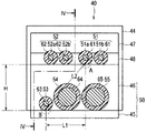
図3に示すように、対を成す画像信号ケーブル51a,51bからなる画像ケーブル51および対を成す制御信号ケーブル52a,52bからなるその他の制御ケーブル52は、リジット基板46の幅方向に並設され、それらの外皮が剥ぎ取られたそれぞれのケーブル芯線61,62がリジット基板46の表面上に設けられた複数のケーブル接続ランド(不図示)と半田付けにより接続される。
Next, the connection configuration of the
As shown in FIG. 3, the
具体的には、撮像装置40を後方から見たときに、図3に示すように、対を成す画像信号ケーブル51a,51bが右側となり、対を成す制御信号ケーブル52a、52bが左側となるように、回路基板部50の上段側となるリジット基板46の表面上で並設するように接続される。
Specifically, when the
同期信号ケーブル53、電源ケーブル54およびGNDケーブル55は、FPC45の幅方向に並設され、それらの外皮が剥ぎ取られたケーブル芯線63,64,65が、回路基板部50の下段側となるFPC45の表面上に設けられた複数のケーブル接続ランド(不図示)と半田付けにより接続される。
The
即ち、画像ケーブル51およびその他の制御ケーブル52と、同期信号ケーブル53、電源ケーブル54およびGNDケーブル55とは、FPC45の表面およびリジット基板46の表面による高低差となる回路基板部50の高さ方向に所定の距離Hで離間するように接続される。
That is, the
なお、画像ケーブル51は、リジット基板46の内方側となる中央寄りで接続される一方の画像信号ケーブル51aおよびリジット基板46の外方側となる側部寄り(ここでは後方から見た右側)で接続される他方の画像信号ケーブル51bの両方が同期信号ケーブル53に対して、回路基板部50の高さ方向に所定の距離Hで離間する位置で接続されている。
The
従って、画像ケーブル51と同期信号ケーブル53は、少なくとも回路基板部50の高さ方向に所定の距離Hで離間する位置で接続されている。
Accordingly, the
これに加えて、画像ケーブル51のうち、一方の上記画像信号ケーブル51aのケーブル芯線61がケーブル接続ランドと接続された接続部Aと、後方から見たFPC45の左側で同期信号ケーブル53のケーブル芯線63がケーブル接続ランドと接続された接続部Bとが、回路基板部50の幅方向に所定の距離L1で離間するように接続されている。
In addition to this, in the
そのため、一方の上記画像信号ケーブル51aよりもリジット基板46の側部(図3においては右側部)よりに位置する他方の上記画像信号ケーブル51bも、同期信号ケーブル53に対して、回路基板部50の幅方向に所定の距離L1以上で離間する位置で接続されている。
Therefore, the other
従って、画像ケーブル51と同期信号ケーブル53は、回路基板部50の幅方向に少なくとも所定の距離L1で離間する位置で接続されている。
Accordingly, the
なお、画像信号ケーブル51aの上記接続部Aと同期信号ケーブル53の上記接続部Bは、撮像装置40の回路基板部50を構成するFPC45およびリジット基板46の長手方向に直交する断面(短手方向の断面)における対角方向に所定の距離L2で離間している。なお、ここでの回路基板部50の長手方向は、撮影光軸Oに沿った方向である。
The connection portion A of the
そのため、一方の上記画像信号ケーブル51aよりもリジット基板46の側部よりに位置する他方の上記画像信号ケーブル51bも、同期信号ケーブル53に対して、回路基板部50の長手方向に直交する断面(短手方向の断面)における対角方向に所定の距離L2以上で離間する位置で接続されている。
For this reason, the other
従って、画像ケーブル51と画像信号ケーブル51bは、回路基板部50の長手方向に直交する断面(短手方向の断面)における対角方向に少なくとも所定の距離L2で離間する位置で接続されている。
Accordingly, the
さらに、上記画像信号ケーブル51aの上記接続部Aと、同期信号ケーブル53の上記接続部Bとが、図4に示すように、回路基板部50の側面視において長手方向に所定の距離L3で離間する位置で接続されている。
Further, the connection portion A of the
そのため、一方の上記画像信号ケーブル51aと幅方向に並設された他方の上記画像信号ケーブル51bも、同期信号ケーブル53に対して、回路基板部50の側面視において長手方向に所定の距離L3以上で離間する位置で接続されている。
For this reason, the one
従って、画像ケーブル51と画像信号ケーブル51bは、回路基板部50の側面視において長手方向に少なくとも所定の距離L3で離間する位置で接続されている。
Accordingly, the
なお、画像信号ケーブル51aの上記接続部Aと同期信号ケーブル53の上記接続部Bは、撮像装置40の回路基板部50を構成するFPC45およびリジット基板46の長手方向の断面における対角方向に所定の距離L4で離間している。
The connection portion A of the
そのため、一方の上記画像信号ケーブル51aに並設された他方の上記画像信号ケーブル51bも、同期信号ケーブル53に対して、回路基板部50の長手方向の断面における対角方向に所定の距離L4以上で離間する位置で接続されている。
Therefore, the other
従って、画像ケーブル51と画像信号ケーブル51bは、回路基板部50の長手方向の断面における対角方向に少なくとも所定の距離L4で離間するように接続されている。
Therefore, the
さらに、上記画像信号ケーブル51aの上記接続部Aと、同期信号ケーブル53の上記接続部Bとが、図5に示すように、回路基板部50の上面視において所定の距離L5で離間する位置で接続されている。
Further, as shown in FIG. 5, the connection portion A of the
そのため、一方の上記画像信号ケーブル51aと幅方向に並設された他方の上記画像信号ケーブル51bも、同期信号ケーブル53に対して、回路基板部50の上面視において所定の距離L5以上で離間する位置で接続されている。
Therefore, the one
従って、画像ケーブル51と画像信号ケーブル51bは、回路基板部50の上面視において少なくとも所定の距離L5で離間する位置で接続されている。
Therefore, the
以上に説明したように、本実施の形態の撮像装置40は、特に、同期信号ケーブル53接続されるFPC45の表面と画像ケーブル51が接続されるリジット基板46との表面とに所定の距離Hの段差を設け、この段差による高低差に加え、回路基板部50の長手方向に側面視においては所定の距離L3で離間する位置、且つ上面視においては所定の距離L5で離間する位置に同期信号ケーブル53と画像ケーブル51を接続した構成となっている。
As described above, the
このように撮像装置40は、画像ケーブル51と同期信号ケーブル53が空間的に離間して接続した構成としているため、同期信号ケーブル53から画像ケーブル51への電磁波の影響を抑制して、画像ケーブル51で伝送する画像信号への電磁波の干渉によって生じるノイズを抑制することができる。これにより、モニタに表示する内視鏡画像に乱れが生じることなく安定したものとなる。
As described above, since the
なお、撮像装置40は、リジット基板46の厚み、FPC45との接着層などによって高さ方向に所定の距離Hの段差を設けた構成を説明したが、その段差の高低差は0.2mm〜4.0mmの範囲内であることが好ましく、固体撮像素子44の高さ寸法と各種ケーブルの太さに応じて、この段差の大きさを選択することができる。
In addition, although the
さらに、リジット基板46、このリジット基板46に実装する電子部品47,48、画像ケーブル51、その他の制御ケーブル52、同期信号ケーブル53、電源ケーブル54およびGNDケーブル55の各種ケーブルは、固体撮像素子44の投影面積内に収まるように配置することで小型の撮像装置40が実現できる。
Further, the
即ち、撮像装置40は、図3に示したように、リジット基板46、このリジット基板46の上面に実装される2つの電子部品47,48、FPC45またはリジット基板46に接続される画像ケーブル51、その他の制御ケーブル52、同期信号ケーブル53、電源ケーブル54およびGNDケーブル55の各種ケーブルの全てが固体撮像素子44の投影面積内に収まるように配置されている。このため、撮像装置40の小型化が実現できる。
That is, as shown in FIG. 3, the
なお、撮像装置40は、固体撮像素子44の投影面積内にリジット基板46、電子部品47,48および全ての各種ケーブルが収まり、且つFPC45に設けられた下段側のケーブル接続ランドに接続される同期信号ケーブル53、電源ケーブル54およびGNDケーブル55がリジット基板46に設けられた上段側のケーブル接続ランドに接続される画像ケーブル51、およびその他の制御ケーブル52に干渉しないような所定の距離Hを有するFPC45の表面とリジット基板46の表面による段差とすることが好ましい。
Note that the
このような段差の高低差は、リジット基板46の厚みによって、所定の距離Hを有した比較的に大きなものとして容易に得ることができる。そのため、比較的に太径の電源ケーブル54、GNDケーブル55などをFPC45に設けられる下段側のケーブル接続ランドに接続することで、これら電源ケーブル54およびGNDケーブル55が固体撮像素子44の投影面積内からはみ出し難く、撮像装置40の細径化が容易になる。
Such a height difference of the step can be easily obtained as a relatively large one having a predetermined distance H depending on the thickness of the
なお、各種ケーブルのうち、比較的に太径としては同軸ケーブルを用いたものとなるため、電源ケーブル54またはGNDケーブル55に限らず、同軸ケーブルをFPC45に設けられる下段側のケーブル接続ランドに接続して、固体撮像素子44の投影面積内からはみ出し難くするとよい。
Of the various cables, a coaxial cable is used for a relatively large diameter, so that the coaxial cable is not limited to the
さらに、上述した撮像装置40では、回路基板部50の上段側に画像ケーブル51を接続し、回路基板部50の下段側に同期信号ケーブル53を接続した構成としたが、画像ケーブル51と同期信号ケーブル53が空間的に離間していればよいため、画像ケーブル51を下段側に、同期信号ケーブル53を上段側に、それぞれが上述した所定の距離(L1〜L5)で離間した位置に接続する構成としてもよい。
Furthermore, in the
以上の説明により、本実施の形態の撮像装置40は、特に、リジット基板46のケーブル接続ランド上に中継部材を設けたり、各種信号ケーブルの接続部に高低差を設けたり、FPC45またはリジット基板46の表裏面にケーブル接続用ランドを設けたりすることなく、簡便な構成として、画像信号に発生するノイズを低減して安定した画像が得られる小型な構成とすることができる。このように、撮像装置40が小型となるため、内視鏡2は、撮像装置40を実装する挿入部4の先端部31の小型化が可能となり、その結果、挿入部4を細径化できる。
As described above, in the
(変形例)
なお、図6および図7に示すように、リジット基板46の幅方向の寸法を小さくして、このリジット基板46の側面からFPC45に空いた領域を設け、この領域上に電子部品49を実装したり、同期信号ケーブル53を接続したりしてもよい。
(Modification)
As shown in FIGS. 6 and 7, the width of the
この変形例においても、上述と同様に、画像ケーブル51のうち、一方の上記画像信号ケーブル51aのケーブル芯線61がケーブル接続ランドと接続された接続部Aと、後方から見たFPC45の左側で同期信号ケーブル53のケーブル芯線63がケーブル接続ランドと接続された接続部Bとが、図6に示すように、回路基板部50の幅方向に所定の距離L6で離間するように接続されている。
Also in this modified example, as described above, among the
そのため、一方の上記画像信号ケーブル51aよりもリジット基板46の側部よりに位置する他方の上記画像信号ケーブル51bも、同期信号ケーブル53に対して、回路基板部50の幅方向に所定の距離L6以上で離間する位置で接続されている。
Therefore, the other
従って、画像ケーブル51と同期信号ケーブル53は、回路基板部50の幅方向に少なくとも所定の距離L6で離間する位置で接続されている。
Therefore, the
さらに、画像信号ケーブル51aの上記接続部Aと同期信号ケーブル53の上記接続部Bは、回路基板部50の長手方向に直交する断面における対角方向に所定の距離L7で離間している。
Further, the connection portion A of the
そのため、一方の上記画像信号ケーブル51aよりもリジット基板46の側部よりに位置する他方の上記画像信号ケーブル51bも、同期信号ケーブル53に対して、回路基板部50の長手方向に直交する断面における対角方向に所定の距離L7以上で離間する位置で接続されている。
Therefore, the other
従って、画像ケーブル51と画像信号ケーブル51bは、回路基板部50の長手方向に直交する断面(短手方向の断面)における対角方向に少なくとも所定の距離L7で離間する位置で接続されている。
Accordingly, the
なお、回路基板部50の長手方向においては、図7に示すように、画像信号ケーブル51aの上記接続部Aと同期信号ケーブル53の上記接続部Bが同位置に接続されており、回路基板部50の高さ方向に所定の距離L8で離間している。
In the longitudinal direction of the
そのため、一方の上記画像信号ケーブル51aよりもリジット基板46の側部よりに位置する他方の上記画像信号ケーブル51bも、同期信号ケーブル53に対して、回路基板部50の高さ方向に所定の距離L8で離間する位置で接続されている。
Therefore, the other
従って、画像ケーブル51と画像信号ケーブル51bは、リジット基板46の高さ方向に少なくとも所定の距離L8で離間する位置で接続されている。この所定の距離L8は、FPC45の表面およびリジット基板46の表面による高低差となる撮像装置40の高さ方向の所定の距離Hと略同じ(L8≒H)である。
Therefore, the
このような構成としても、撮像装置40は、画像ケーブル51と同期信号ケーブル53が空間的に離間して接続でき、上述の構成よりは効果が薄れるが、同期信号ケーブル53から画像ケーブル51への電磁波の影響を抑制して、画像ケーブル51で伝送する画像信号への電磁波の干渉によって生じるノイズを抑制することができる。その結果、モニタに表示する内視鏡画像に乱れが生じることなく安定したものとなる。
Even in such a configuration, the
上述の実施の形態に記載した発明は、その実施の形態および変形例に限ることなく、その他、実施段階ではその要旨を逸脱しない範囲で種々の変形を実施し得ることが可能である。さらに、上記実施の形態には、種々の段階の発明が含まれており、開示される複数の構成要件における適宜な組合せにより種々の発明が抽出され得るものである。 The invention described in the above-described embodiment is not limited to the embodiment and modifications, and various modifications can be made without departing from the scope of the invention in the implementation stage. Further, the above embodiments include inventions at various stages, and various inventions can be extracted by appropriately combining a plurality of disclosed constituent elements.
例えば、実施の形態に示される全構成要件から幾つかの構成要件が削除されても、述べられている課題が解決でき、述べられている効果が得られる場合には、この構成要件が削除された構成が発明として抽出され得るものである。 For example, even if some constituent requirements are deleted from all the constituent requirements shown in the embodiment, the described requirements can be deleted if the stated problem can be solved and the stated effect can be obtained. The configuration can be extracted as an invention.
1…内視鏡装置
2…電子内視鏡
3…周辺装置
4…挿入部
5…操作部
6…ユニバーサルコード
7…内視鏡コネクタ
8…架台
9…光源装置
10…ビデオプロセッサ
11…接続ケーブル
12…キーボード
13…モニタ
14…湾曲操作ノブ
15,16…ボタン類
17…処置具挿入口
18…固定用レバー
21…上下湾曲操作用ノブ
22…左右湾曲操作用ノブ
31…先端部
32…湾曲部
33…可撓管部
40…撮像装置
41…先端部本体
42…硬質管
43…レンズユニット
43a…対物レンズ
43b…レンズホルダ
44…固体撮像素子
44a…受光素子部
45…フレキシブルプリント基板
45a…封止樹脂
46…リジット基板
47,48…電子部品
49…ガラスリッド
50…回路基板部
51…画像ケーブル
51a,51b…画像信号ケーブル
52…制御ケーブル
52a,52b…制御信号ケーブル
53…同期信号ケーブル
54…電源ケーブル
55…グランドケーブル
61,62,63,64,65…ケーブル芯線
O…撮影光軸
DESCRIPTION OF SYMBOLS 1 ...
Claims (9)
前記固体撮像素子の駆動回路を構成する電子部品が実装され、段差が設けられた回路基板部と、
前記回路基板部に設けられたケーブル接続ランドと接続される複数のケーブルと、
を備え、
前記複数のケーブルのうち、画像信号を伝送する画像ケーブルおよび同期信号を伝送する同期信号ケーブルは、前記段差により離間する前記回路基板部の異なる表面に接続されていることを特徴とする撮像装置。 A solid-state imaging device having a light receiving element portion for detecting a subject image;
A circuit board portion on which electronic components constituting a driving circuit of the solid-state imaging device are mounted and provided with a step, and
A plurality of cables connected to cable connection lands provided in the circuit board unit;
With
An image pickup apparatus, wherein among the plurality of cables, an image cable for transmitting an image signal and a synchronization signal cable for transmitting a synchronization signal are connected to different surfaces of the circuit board portion separated by the step.
前記画像ケーブルおよび前記同期信号ケーブルは、前記回路基板部の前記高さ方向に互いが離間する位置に接続されていることを特徴とする請求項1に記載の撮像装置。 The circuit board portion is formed by laminating and connecting a rigid board on a flexible printed board, and the step is formed in the height direction by the surface of the flexible printed board and the surface of the rigid board,
The imaging device according to claim 1, wherein the image cable and the synchronization signal cable are connected to each other at positions separated from each other in the height direction of the circuit board unit.
Priority Applications (5)
| Application Number | Priority Date | Filing Date | Title |
|---|---|---|---|
| JP2013087584A JP6321917B2 (en) | 2013-04-18 | 2013-04-18 | Imaging apparatus and electronic endoscope |
| PCT/JP2014/060818 WO2014171482A1 (en) | 2013-04-18 | 2014-04-16 | Image capturing device and electronic endoscope |
| EP14784990.5A EP2987448A4 (en) | 2013-04-18 | 2014-04-16 | Image capturing device and electronic endoscope |
| CN201480021722.3A CN105208908A (en) | 2013-04-18 | 2014-04-16 | Image capturing device and electronic endoscope |
| US14/885,291 US20160037029A1 (en) | 2013-04-18 | 2015-10-16 | Image pickup apparatus and electronic endoscope |
Applications Claiming Priority (1)
| Application Number | Priority Date | Filing Date | Title |
|---|---|---|---|
| JP2013087584A JP6321917B2 (en) | 2013-04-18 | 2013-04-18 | Imaging apparatus and electronic endoscope |
Publications (2)
| Publication Number | Publication Date |
|---|---|
| JP2014210041A true JP2014210041A (en) | 2014-11-13 |
| JP6321917B2 JP6321917B2 (en) | 2018-05-09 |
Family
ID=51930297
Family Applications (1)
| Application Number | Title | Priority Date | Filing Date |
|---|---|---|---|
| JP2013087584A Active JP6321917B2 (en) | 2013-04-18 | 2013-04-18 | Imaging apparatus and electronic endoscope |
Country Status (1)
| Country | Link |
|---|---|
| JP (1) | JP6321917B2 (en) |
Cited By (2)
| Publication number | Priority date | Publication date | Assignee | Title |
|---|---|---|---|---|
| WO2017158722A1 (en) * | 2016-03-15 | 2017-09-21 | オリンパス株式会社 | Image pickup device, endoscope, and method for manufacturing image pickup device |
| CN113196738A (en) * | 2018-12-19 | 2021-07-30 | Lg伊诺特有限公司 | Camera module |
Citations (3)
| Publication number | Priority date | Publication date | Assignee | Title |
|---|---|---|---|---|
| JP2003010111A (en) * | 2001-06-27 | 2003-01-14 | Olympus Optical Co Ltd | Imaging device |
| JP2011050497A (en) * | 2009-08-31 | 2011-03-17 | Olympus Medical Systems Corp | Imaging device and electronic endoscope |
| JP2012183330A (en) * | 2012-05-14 | 2012-09-27 | Olympus Medical Systems Corp | Imaging device |
-
2013
- 2013-04-18 JP JP2013087584A patent/JP6321917B2/en active Active
Patent Citations (3)
| Publication number | Priority date | Publication date | Assignee | Title |
|---|---|---|---|---|
| JP2003010111A (en) * | 2001-06-27 | 2003-01-14 | Olympus Optical Co Ltd | Imaging device |
| JP2011050497A (en) * | 2009-08-31 | 2011-03-17 | Olympus Medical Systems Corp | Imaging device and electronic endoscope |
| JP2012183330A (en) * | 2012-05-14 | 2012-09-27 | Olympus Medical Systems Corp | Imaging device |
Cited By (5)
| Publication number | Priority date | Publication date | Assignee | Title |
|---|---|---|---|---|
| WO2017158722A1 (en) * | 2016-03-15 | 2017-09-21 | オリンパス株式会社 | Image pickup device, endoscope, and method for manufacturing image pickup device |
| US11134829B2 (en) | 2016-03-15 | 2021-10-05 | Olympus Corporation | Image pickup apparatus, endoscope, and method for manufacturing image pickup apparatus |
| CN113196738A (en) * | 2018-12-19 | 2021-07-30 | Lg伊诺特有限公司 | Camera module |
| CN113196738B (en) * | 2018-12-19 | 2023-09-29 | Lg伊诺特有限公司 | camera module |
| US11863850B2 (en) | 2018-12-19 | 2024-01-02 | Lg Innotek Co., Ltd. | Camera module |
Also Published As
| Publication number | Publication date |
|---|---|
| JP6321917B2 (en) | 2018-05-09 |
Similar Documents
| Publication | Publication Date | Title |
|---|---|---|
| WO2014171482A1 (en) | Image capturing device and electronic endoscope | |
| CN107149460B (en) | Endoscope with a detachable handle | |
| CN106886089B (en) | Endoscope with a detachable handle | |
| EP3050491B1 (en) | Endoscope device | |
| US20180070803A1 (en) | Imaging device and endoscope system | |
| WO2016063603A1 (en) | Solid-state imaging device and electronic endoscope provided with solid-state imaging device | |
| JP5977892B1 (en) | Imaging unit and electronic endoscope provided with the imaging unit | |
| JP2011212161A (en) | Solid-state image pickup device and endoscopic device | |
| WO2015045630A1 (en) | Imaging module and endoscope device | |
| WO2019044609A1 (en) | Endoscope | |
| JP6650378B2 (en) | Endoscope | |
| JP6205228B2 (en) | Imaging module and endoscope apparatus | |
| WO2017130371A1 (en) | Image pickup device and endoscope | |
| US10517465B2 (en) | Cable connection structure and endoscope apparatus | |
| JP6321917B2 (en) | Imaging apparatus and electronic endoscope | |
| CN107115088B (en) | Endoscope with a detachable handle | |
| JP2016214660A (en) | Medical camera head and medical camera device | |
| JP2015080675A (en) | Endoscope and endoscope manufacturing method | |
| JP6321916B2 (en) | Imaging apparatus and electronic endoscope | |
| JP2018007715A (en) | Endoscope | |
| JP6081347B2 (en) | Imaging unit and endoscope | |
| JP7029296B2 (en) | Endoscope board unit | |
| JP6223092B2 (en) | Endoscope device | |
| WO2017115441A1 (en) | Mounting structure, image pickup device, and endoscope | |
| JP2015080633A (en) | Electric unit and endoscope apparatus using electric unit |
Legal Events
| Date | Code | Title | Description |
|---|---|---|---|
| A621 | Written request for application examination |
Free format text: JAPANESE INTERMEDIATE CODE: A621 Effective date: 20160325 |
|
| A131 | Notification of reasons for refusal |
Free format text: JAPANESE INTERMEDIATE CODE: A131 Effective date: 20161108 |
|
| A601 | Written request for extension of time |
Free format text: JAPANESE INTERMEDIATE CODE: A601 Effective date: 20161118 |
|
| A521 | Request for written amendment filed |
Free format text: JAPANESE INTERMEDIATE CODE: A523 Effective date: 20170302 |
|
| A131 | Notification of reasons for refusal |
Free format text: JAPANESE INTERMEDIATE CODE: A131 Effective date: 20170711 |
|
| A601 | Written request for extension of time |
Free format text: JAPANESE INTERMEDIATE CODE: A601 Effective date: 20170901 |
|
| A521 | Request for written amendment filed |
Free format text: JAPANESE INTERMEDIATE CODE: A523 Effective date: 20171106 |
|
| TRDD | Decision of grant or rejection written | ||
| A01 | Written decision to grant a patent or to grant a registration (utility model) |
Free format text: JAPANESE INTERMEDIATE CODE: A01 Effective date: 20180313 |
|
| A61 | First payment of annual fees (during grant procedure) |
Free format text: JAPANESE INTERMEDIATE CODE: A61 Effective date: 20180406 |
|
| R150 | Certificate of patent or registration of utility model |
Ref document number: 6321917 Country of ref document: JP Free format text: JAPANESE INTERMEDIATE CODE: R150 |
|
| R250 | Receipt of annual fees |
Free format text: JAPANESE INTERMEDIATE CODE: R250 |
|
| R250 | Receipt of annual fees |
Free format text: JAPANESE INTERMEDIATE CODE: R250 |
|
| R250 | Receipt of annual fees |
Free format text: JAPANESE INTERMEDIATE CODE: R250 |
|
| R250 | Receipt of annual fees |
Free format text: JAPANESE INTERMEDIATE CODE: R250 |