JP2012502613A - Receive antenna placement for wireless power - Google Patents
Receive antenna placement for wireless power Download PDFInfo
- Publication number
- JP2012502613A JP2012502613A JP2011526275A JP2011526275A JP2012502613A JP 2012502613 A JP2012502613 A JP 2012502613A JP 2011526275 A JP2011526275 A JP 2011526275A JP 2011526275 A JP2011526275 A JP 2011526275A JP 2012502613 A JP2012502613 A JP 2012502613A
- Authority
- JP
- Japan
- Prior art keywords
- electronic device
- loop conductor
- antenna
- wireless
- receive antenna
- Prior art date
- Legal status (The legal status is an assumption and is not a legal conclusion. Google has not performed a legal analysis and makes no representation as to the accuracy of the status listed.)
- Withdrawn
Links
Images


Classifications
-
- H—ELECTRICITY
- H01—ELECTRIC ELEMENTS
- H01Q—ANTENNAS, i.e. RADIO AERIALS
- H01Q1/00—Details of, or arrangements associated with, antennas
- H01Q1/12—Supports; Mounting means
- H01Q1/22—Supports; Mounting means by structural association with other equipment or articles
- H01Q1/24—Supports; Mounting means by structural association with other equipment or articles with receiving set
- H01Q1/248—Supports; Mounting means by structural association with other equipment or articles with receiving set provided with an AC/DC converting device, e.g. rectennas
-
- H—ELECTRICITY
- H01—ELECTRIC ELEMENTS
- H01Q—ANTENNAS, i.e. RADIO AERIALS
- H01Q1/00—Details of, or arrangements associated with, antennas
- H01Q1/12—Supports; Mounting means
- H01Q1/22—Supports; Mounting means by structural association with other equipment or articles
- H01Q1/2208—Supports; Mounting means by structural association with other equipment or articles associated with components used in interrogation type services, i.e. in systems for information exchange between an interrogator/reader and a tag/transponder, e.g. in Radio Frequency Identification [RFID] systems
- H01Q1/2225—Supports; Mounting means by structural association with other equipment or articles associated with components used in interrogation type services, i.e. in systems for information exchange between an interrogator/reader and a tag/transponder, e.g. in Radio Frequency Identification [RFID] systems used in active tags, i.e. provided with its own power source or in passive tags, i.e. deriving power from RF signal
-
- H—ELECTRICITY
- H01—ELECTRIC ELEMENTS
- H01Q—ANTENNAS, i.e. RADIO AERIALS
- H01Q1/00—Details of, or arrangements associated with, antennas
- H01Q1/12—Supports; Mounting means
- H01Q1/22—Supports; Mounting means by structural association with other equipment or articles
- H01Q1/24—Supports; Mounting means by structural association with other equipment or articles with receiving set
- H01Q1/241—Supports; Mounting means by structural association with other equipment or articles with receiving set used in mobile communications, e.g. GSM
- H01Q1/242—Supports; Mounting means by structural association with other equipment or articles with receiving set used in mobile communications, e.g. GSM specially adapted for hand-held use
- H01Q1/243—Supports; Mounting means by structural association with other equipment or articles with receiving set used in mobile communications, e.g. GSM specially adapted for hand-held use with built-in antennas
-
- H—ELECTRICITY
- H01—ELECTRIC ELEMENTS
- H01Q—ANTENNAS, i.e. RADIO AERIALS
- H01Q7/00—Loop antennas with a substantially uniform current distribution around the loop and having a directional radiation pattern in a plane perpendicular to the plane of the loop
-
- H—ELECTRICITY
- H02—GENERATION; CONVERSION OR DISTRIBUTION OF ELECTRIC POWER
- H02J—CIRCUIT ARRANGEMENTS OR SYSTEMS FOR SUPPLYING OR DISTRIBUTING ELECTRIC POWER; SYSTEMS FOR STORING ELECTRIC ENERGY
- H02J50/00—Circuit arrangements or systems for wireless supply or distribution of electric power
- H02J50/005—Mechanical details of housing or structure aiming to accommodate the power transfer means, e.g. mechanical integration of coils, antennas or transducers into emitting or receiving devices
-
- H—ELECTRICITY
- H02—GENERATION; CONVERSION OR DISTRIBUTION OF ELECTRIC POWER
- H02J—CIRCUIT ARRANGEMENTS OR SYSTEMS FOR SUPPLYING OR DISTRIBUTING ELECTRIC POWER; SYSTEMS FOR STORING ELECTRIC ENERGY
- H02J50/00—Circuit arrangements or systems for wireless supply or distribution of electric power
- H02J50/10—Circuit arrangements or systems for wireless supply or distribution of electric power using inductive coupling
- H02J50/12—Circuit arrangements or systems for wireless supply or distribution of electric power using inductive coupling of the resonant type
-
- H—ELECTRICITY
- H02—GENERATION; CONVERSION OR DISTRIBUTION OF ELECTRIC POWER
- H02J—CIRCUIT ARRANGEMENTS OR SYSTEMS FOR SUPPLYING OR DISTRIBUTING ELECTRIC POWER; SYSTEMS FOR STORING ELECTRIC ENERGY
- H02J50/00—Circuit arrangements or systems for wireless supply or distribution of electric power
- H02J50/20—Circuit arrangements or systems for wireless supply or distribution of electric power using microwaves or radio frequency waves
-
- H—ELECTRICITY
- H02—GENERATION; CONVERSION OR DISTRIBUTION OF ELECTRIC POWER
- H02J—CIRCUIT ARRANGEMENTS OR SYSTEMS FOR SUPPLYING OR DISTRIBUTING ELECTRIC POWER; SYSTEMS FOR STORING ELECTRIC ENERGY
- H02J50/00—Circuit arrangements or systems for wireless supply or distribution of electric power
- H02J50/80—Circuit arrangements or systems for wireless supply or distribution of electric power involving the exchange of data, concerning supply or distribution of electric power, between transmitting devices and receiving devices
-
- H—ELECTRICITY
- H02—GENERATION; CONVERSION OR DISTRIBUTION OF ELECTRIC POWER
- H02J—CIRCUIT ARRANGEMENTS OR SYSTEMS FOR SUPPLYING OR DISTRIBUTING ELECTRIC POWER; SYSTEMS FOR STORING ELECTRIC ENERGY
- H02J7/00—Circuit arrangements for charging or depolarising batteries or for supplying loads from batteries
- H02J7/00032—Circuit arrangements for charging or depolarising batteries or for supplying loads from batteries characterised by data exchange
- H02J7/00036—Charger exchanging data with battery
-
- H—ELECTRICITY
- H02—GENERATION; CONVERSION OR DISTRIBUTION OF ELECTRIC POWER
- H02J—CIRCUIT ARRANGEMENTS OR SYSTEMS FOR SUPPLYING OR DISTRIBUTING ELECTRIC POWER; SYSTEMS FOR STORING ELECTRIC ENERGY
- H02J7/00—Circuit arrangements for charging or depolarising batteries or for supplying loads from batteries
- H02J7/00047—Circuit arrangements for charging or depolarising batteries or for supplying loads from batteries with provisions for charging different types of batteries
Abstract
【解決手段】 例示的実施形態は無線充電に向けられている。電子デバイスは、電子デバイス中に統合されかつ無線送信アンテナから無線電力を受け取るように構成されている少なくとも1つの受信アンテナを具備し得る。少なくとも1つの受信アンテナのループ導電体は電子デバイス内の各導電性構成要素から離されて構成されており得、その間に、ループ導電体の周囲での磁界の形成を可能にするように適合されている隙間を有する。
【選択図】 図13An exemplary embodiment is directed to wireless charging. The electronic device may comprise at least one receive antenna integrated into the electronic device and configured to receive wireless power from the wireless transmit antenna. The loop conductor of the at least one receiving antenna may be configured separately from each conductive component in the electronic device, between which it is adapted to allow the formation of a magnetic field around the loop conductor Have gaps.
[Selected figure] Figure 13
Description
この出願は、2008年9月8日に出願された「INTEGRATION OF WIRELESS CHARGING ANTENNAS INTO MOBILE DEVICES」と題された米国仮出願61/095,26435の第119条(e)の下の優先権を要求する。その開示の全体は、参照によって本明細書に取り込まれる。 This application claims priority under section 119 (e) of US Provisional Application 61 / 095,26435, entitled "INTEGRATION OF WIRELESS CHARGING ANTENNAS INTO MOBILE DEVICES," filed on September 8, 2008. Do. The entire disclosure is incorporated herein by reference.
本発明は、概して無線充電に関し、より具体的には電子デバイス中への統合に向けて構成されている無線受信アンテナに関する装置、システム、および方法に関する。 The present invention relates generally to wireless charging, and more particularly to an apparatus, system and method for a wireless receiving antenna configured for integration into an electronic device.
典型的には、無線電子デバイスのような電力供給される装置は各々、自身の有線の充電器および電源(これは通常、交流(AC)電力コンセントである)を必要とする。そのような有線の構成は、多くの装置が充電を必要とする場合、使いにくくなる。 Typically, each powered device, such as a wireless electronic device, requires its own wired charger and power supply (which is usually an alternating current (AC) power outlet). Such wired configurations can be difficult to use if many devices require charging.
送信器と充電される電子デバイスに結合されている受信器との間の無線経由または無線送電を使用するアプローチが開発されている。受信アンテナは放射された電力を集めて、これを、装置に電力供給するためまたは装置のバッテリを充電するのに使用可能な電力に整流する。 An approach has been developed that uses over-the-air or wireless transmission between the transmitter and a receiver coupled to the electronic device being charged. The receiving antenna collects the radiated power and rectifies it into power that can be used to power the device or charge the battery of the device.
無線エネルギー伝送は、電力供給または充電されるホスト電子デバイスに埋め込まれている、送信アンテナ、無線受信アンテナ、および整流回路を結合することに基づき得る。無線充電における重要な要素は、無線受信アンテナは電子デバイス内に組み込まれており得る無線受信アンテナのQ値(quality factor)である。無線受信アンテナのQ値は、無線受信アンテナの近くに存在する磁界によって影響され得る。無線受信アンテナに加えて、電子デバイスは様々な導電性の構成要素(コンポーネント、部品、component)を含んでおり得る。導電性構成要素は、関連する無線受信アンテナの性能に悪影響を及ぼし得る。具体的には、導電性構成要素は、無線受信アンテナに隣接して存在する磁界の振る舞いに悪影響を与え得る。そこで、統合された(一体化された、integrated)受信アンテナを有しかつ統合された受信アンテナのQ値およびインダクタンスを向上するように構成されている電子デバイスを提供する必要性がある。 Wireless energy transmission may be based on combining a transmit antenna, a wireless receive antenna, and a rectifier circuit embedded in a host electronic device to be powered or charged. An important factor in wireless charging is the quality factor of the wireless receiving antenna, which may be incorporated into the electronic device. The Q value of the wireless receive antenna can be influenced by the magnetic field present near the wireless receive antenna. In addition to the wireless receiving antenna, the electronic device may include various conductive components. Conductive components can adversely affect the performance of the associated wireless receive antenna. In particular, the conductive component can adversely affect the behavior of the magnetic field present adjacent to the wireless receiving antenna. Thus, there is a need to provide an electronic device having an integrated (integrated) receive antenna and configured to improve the Q factor and inductance of the integrated receive antenna.
「例示的」という文言は、「例、実例、または例証として役立つ」ことを意味するために本明細書において使用されている。「例示的」と本明細書において記述されている実施形態はいずれも、好ましいもの、または他の実施形態よりも有利なものとして必ずしも解釈されるべきではない。 The word "exemplary" is used herein to mean "serving as an example, instance, or illustration." Any embodiment described herein as "exemplary" is not necessarily to be construed as preferred or advantageous over other embodiments.
添付図面との関連で以下に記述されている詳細な説明は、例示的な実施形態の記述であることを意図されており、本発明を実行されることが可能な唯一の実施形態を表わすことを意図されていない。この記述の全体にわたって使用されている文言「例示的」は、「例、実例、または例証として役立つ」ことを意味し、必ずしも好ましいものまたは他の例示的な実施形態よりも有利なものとして解釈されるべきではない。詳細な説明は、発明の例示的な実施形態についての十分な理解をもたらす目的で諸詳細事項を含んでいる。発明の例示的な実施形態がこれらの詳細事項無しで実行され得ることは当業者にとって明らかだろう。いくつかの事例では、周知の構造および装置は本明細書において示されている例示的な実施形態の新規性を不明瞭にしないようにするためにブロック図の形態で示されている。 The detailed description set forth below in connection with the accompanying drawings is intended to be a description of exemplary embodiments and represent the only embodiments in which the present invention can be practiced. Not intended. The word "exemplary" is used throughout this description to mean "serving as an example, instance, or illustration" and is necessarily to be construed as preferred or advantageous over other exemplary embodiments. It should not be. The detailed description includes details for the purpose of providing a thorough understanding of the exemplary embodiments of the invention. It will be apparent to one skilled in the art that the exemplary embodiments of the invention may be practiced without these details. In some instances, well-known structures and devices are shown in block diagram form in order not to obscure the novelty of the exemplary embodiments set forth herein.
文言「無線電力(wireless power)」は、電界、磁界、電磁界に関連するエネルギーの任意の形態、または送信器から物理的な電磁気導体を使用することなく受信器に送信されるエネルギーの任意の形態を意味するために本明細書において使用されている。システム中での電力変換は、例えば携帯電話、コードレス電話機、iPod、MP3プレーヤー、ヘッドセットなどを含む装置を無線充電するために本明細書において記述されている。概括的には、無線エネルギー伝送の1つの根本原理は、(例えば30MHz未満の)周波数を使用した磁気結合共振(共鳴)(すなわち共振(共鳴)誘導)を含んでいる。しかしながら、例えば135kHz未満(LF)または13.56MHz(HF)での比較的高い放射レベルでのライセンス免除された動作が許可されている周波数を含む様々な周波数が使用され得る。無線周波数識別子(RFID)システムによって通常使用されるこれらの周波数では、システムは、ヨーロッパでのEN 300330またはアメリカでのFCC Part 15基準のような、干渉波および安全基準に従わなければならない。限定ではなく例証として、省略形LFおよびHFが本明細書において使用されており、「LF」はf0=135kHzを指し、「HF」はf0=13.56MHzを指す。 The term "wireless power" refers to any form of energy associated with electric fields, magnetic fields, electromagnetic fields, or any of the energy transmitted from the transmitter to the receiver without the use of a physical electromagnetic conductor. Used herein to mean form. Power conversion in the system is described herein for wireless charging devices including, for example, cell phones, cordless phones, iPods, MP3 players, headsets and the like. In general, one underlying principle of wireless energy transmission involves magnetic coupling resonance (resonance) (i.e. resonance (resonance) induction) using frequencies (e.g. less than 30 MHz). However, various frequencies may be used, including frequencies for which license-excluded operation at relatively high emission levels, for example below 135 kHz (LF) or 13.56 MHz (HF) is permitted. At these frequencies normally used by radio frequency identification (RFID) systems, the system must comply with interference and safety standards, such as EN 300330 in Europe or FCC Part 15 standards in the United States. By way of illustration and not limitation, the abbreviations LF and HF are used herein, “LF” refers to f 0 = 135 kHz, and “HF” refers to f 0 = 13.56 MHz.
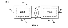
図1は様々な例示的な実施形態に従った、無線送電システム100を図示している。入力電源102は、エネルギー伝送をもたらすための磁界106を生成するための送信器104に提供される。受信器108は磁界106に結合しており、出力電力110を生成する。出力電力110は、出力電力110に結合されている装置(図示せず)による保存または消費ためのものである。送信器104および受信器108はともに、距離112によって離されている。一例示的実施形態では、送信器104および受信器108は相互共振(共鳴)関係に従って構成されており、受信器108の共振(共鳴)振動数と送信器104の共振振動数とが一致している場合、受信器108が磁界106の「近距離場(nera-field)」に位置していると送信器104と受信器108との間の送信損は最小である。
FIG. 1 illustrates a
送信器104は、さらに、エネルギー送信のための手段を提供するために送信アンテナ114を含んでおり、受信器108は、さらに、エネルギー受信または結合のための手段を提供するために受信アンテナ118を含んでいる。送信および受信アンテナは、自身と関連する適用形態(application)および装置に従った大きさとされている。上記のように、効率的なエネルギー伝送は、電磁波中のほとんどのエネルギーを遠距離(far-field)場に伝播するのではなく送信アンテナの近距離場内にあるエネルギーの大部分を受信アンテナに結合することによって起こる。この近距離場にあると、送信アンテナ114と受信アンテナ118との間で結合が確立され得る。この近距離場結合が起こり得るアンテナ114および118の周囲の領域は、本明細書では結合モード領域と称される。
The
図2は、無線送電システムの簡略化された概略図を示している。入力電源102によって駆動される送信器104は、発振器122と、電力増幅器124と、フィルタおよび整合回路126と、を含んでいる。発振器は、所望の周波数を生成するように構成されている。この周波数は調整信号123に応じて調整され得る。発振器信号は、電力増幅器124によって、制御信号125に応じた増幅量で増幅され得る。フィルタおよび整合回路126は、高調波または他の不要な周波数を濾波により除去しかつ送信器104のインピーダンスを送信アンテナ114に整合させるために含まれており得る。
FIG. 2 shows a simplified schematic of the wireless transmission system. The
受信器108は、整合回路132と、図2に示されているようなバッテリ136を充電するかまたは受信器に結合されている装置(図示せず)に電力供給するためのDC電力出力を生成するための整流器および切替え回路134と、を含み得る。整合回路132は、受信器108のインピーダンスを受信アンテナ118に整合するために含まれており得る。
The
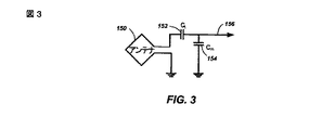
図3に図示されているように、例示的実施形態において使用されるアンテナは「ループ」アンテナ150として構成されており得る。ループ・アンテナ150は、本明細書において、「磁気(磁界)」アンテナ、「共振」アンテナ、または「磁気共振」アンテナとも称され得る。ループ・アンテナは、空芯またはフェライト・コアのような物理的なコアを含んでいるように構成され得る。さらに、空芯ループ・アンテナは、コア領域中での他の構成要素の配置を可能にする。また、空芯ループは、送信アンテナ114(図2)の平面内に受信アンテナ118(図2)を配置することをより簡単に可能にし得、送信アンテナ114(図2)の結合モード(結合されているモード)領域がより効果的であり得る。
As illustrated in FIG. 3, the antenna used in the exemplary embodiment may be configured as a “loop”
上記のように、送信器104と受信器108との間の効率的なエネルギー伝送は、送信器104と受信器108との間での一致またはほぼ一致した共振の際に起こる。しかしながら、送信器と受信器108との間の共振が一致しない場合でも、エネルギーはより低い効率で伝送され得る。エネルギー伝送は、送信アンテナの近距離場からのエネルギーを、送信アンテナからのエネルギーを空きスペースへと伝播するのではなくこの近距離場が確立されている近隣に位置する受信アンテナに結合することによって起こり得る。
As mentioned above, efficient energy transfer between
ループ・アンテナの共振振動数はインダクタンスとキャパシタンスに基づく。ループ・アンテナ中のインダクタンスは普通はループによって形成されたインダクタンスであるが、所望の共振振動数で共振する構造を形成するために普通はキャパシタンスがループ・アンテナのインダクタンスに加えられる。非制限的な例として、シヌソイドまたは疑似シヌソイド信号156を生成する共振回路を形成するために、キャパシタ152およびキャパシタ154がアンテナに加えられ得る。したがって、より大きな直径のループ・アンテナについては、共振を誘起するために必要とされるキャパシタンスの大きさは、ループの直径またはインダクタンスが増加するにつれて減少する。さらに、ループ・アンテナの直径が増加するにつれて、「近傍」結合されている装置にとっての、近距離場の効率的なエネルギー伝送面積は増加する。もちろん、他の共振回路が可能である。別の非制限的な例として、キャパシタはループ・アンテナの2つの端子の間に並列に配置され得る。また、当業者は、送信アンテナにとって共振信号156がループ・アンテナ150への入力であり得ることを認識するだろう。
The resonant frequency of the loop antenna is based on inductance and capacitance. The inductance in the loop antenna is usually the inductance formed by the loop, but usually a capacitance is added to the inductance of the loop antenna to form a structure that resonates at the desired resonant frequency. As a non-limiting example,
本発明の例示的な実施形態は、相互に近距離場内にある2つのアンテナの間で電力を結合することを含んでいる。上記のように、近距離場は、電磁界が存在はするがアンテナから離れる方向に伝搬または放射しないアンテナ周囲の領域である。近距離場は、典型的には、アンテナの物理的体積に近い体積に制限される。発明の例示的な実施形態では、1回巻または多巻きループ・アンテナのようなアンテナが送信(Tx)および受信(Rx)アンテナ・システムの両方のために使用される。なぜなら、恐らくアンテナ周囲のほとんどの環境は、誘電性であって、したがって電界と比較して磁界に対して有する影響がより少ないからである。さらに、支配的に「電気的」アンテナ(例えばダイポールおよびモノポール)として構成されているアンテナまたは磁気的アンテナおよび電気的アンテナの組合せも企図されている。 An exemplary embodiment of the invention involves coupling power between two antennas that are in the near field to each other. As mentioned above, the near field is the area around the antenna where the electromagnetic field is present but does not propagate or radiate away from the antenna. The near field is typically confined to a volume close to the physical volume of the antenna. In exemplary embodiments of the invention, antennas such as single-turn or multi-turn loop antennas are used for both transmit (Tx) and receive (Rx) antenna systems. This is probably because most of the environment around the antenna is dielectric and thus has less influence on the magnetic field compared to the electric field. In addition, antennas or combinations of magnetic and electrical antennas, which are predominantly configured as "electrical" antennas (e.g. dipoles and monopoles) are also contemplated.
Txアンテナは、十分に低い周波数で、かつ上記の遠距離場およびインダクタンス・アプローチで可能なものよりも著しく大きな距離で小さなRxアンテナへの良好な結合効率(例えば>10%)を達成するのに十分な大きさのアンテナ・サイズによって動作させられることが可能である。Txアンテナが適切な大きさにされていれば、ホスト装置上のRxアンテナが、駆動されているTxループ・アンテナの結合モード領域内に(すなわち近距離場または強く結合されている形で)位置すると、高い結合効率(例えば30%)が達成されることが可能である。 The Tx antenna achieves good coupling efficiency (e.g.> 10%) to a small Rx antenna at a sufficiently low frequency and at a significantly greater distance than possible with the above far-field and inductance approaches It is possible to operate with a sufficiently large antenna size. If the Tx antenna is appropriately sized, the Rx antenna on the host device is located within the coupled mode region of the Tx loop antenna being driven (ie in the near field or strongly coupled form) Then, high coupling efficiencies (eg 30%) can be achieved.
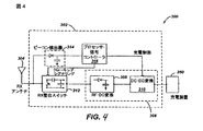
図4は実施形態に従った受信器のブロック図である。受信器300は受信回路302および受信アンテナ304を含んでいる。受信器300は、さらに、受信電力を提供するために装置350に結合している。受信器300は、装置350の外側にあることとして図示されているが、装置350中に統合され得ることに注意されたい。大まかには、エネルギーは、受信アンテナ304に無線で伝播され、次いで受信回路302によって装置350に結合される。
FIG. 4 is a block diagram of a receiver according to an embodiment. The
受信アンテナ304は送信アンテナ204(図10)と同じ周波数で、またはこの同じ周波数の近くで共振するように同調させられる。受信アンテナ304は、送信アンテナ204と同様の寸法にされ、または関連する装置350の寸法に基づいて、別の大きさにされており得る。例として、装置350は、送信アンテナ204の長さまたは直径より小さな直径(diametric)または長さ寸法を有する携帯電子デバイスであり得る。そのような例では、受信アンテナ304は同調キャパシタ(図示せず)のキャパシタンス値を減じかつ受信アンテナのインピーダンスを上げるために多巻きアンテナとして実現され得る。例として、受信アンテナ304は、アンテナ直径を最大限にしかつ受信アンテナのループ数(すなわち巻数)および巻き間(inter-winding、ループ間)キャパシタンスを減らすために装置350の実質的な円周の周囲(around)に配置され得る。
The receive
受信回路302は受信アンテナ304に対するインピーダンス整合をもたらす。受信回路302は、受け取られたRFエネルギー源を装置350による使用のために充電電源に変換するための電力変換回路306を含んでいる。電力変換回路306は、RFから直流へのコンバータ(RF・DCコンバータ)308を含んでおり、またDC・DC変換器310を含んでいる。RF・DCコンバータ308は、受信アンテナ304で受け取られたRFエネルギー信号を非交流電力に整流し、他方、DC・DC変換器310は、整流されたRFエネルギー信号を装置350と適合するエネルギー・ポテンシャル(例えば電圧)に変換する。部分整流器および全整流器、レギュレータ、ブリッジ、ダブラー、線形および切替え変換器を含む様々なRF・直流変換器が企図されている。
The receive
受信回路302は、さらに、受信アンテナ304を電力変換回路306に接続するための、または電力変換回路306を切断するための切替え回路312を含んでおり得る。受信アンテナ304を電力変換回路306から切断することは、装置350の充電を一時停止するだけでなく、より完全に下に説明されるように送信器200(図2)から「見た」「負荷」を変化させる。上に開示されているように、送信器200は、送信器電力増幅器210に提供されるバイアス電流の変動を検出する負荷検知回路216を含んでいる。したがって、送信器200は、受信器が送信器の近距離場内に位置しているときを決定するための機構を有する。
The
受信回路302は、さらに、受け取られたエネルギーの変動を特定するために使用される信号検出器およびビーコン回路314を含んでいる。これらは、送信器から受信器までの情報シグナリング(signaling、伝達)に相当し得る。さらに、シグナリングおよびビーコン回路314は、減じられたRF信号エネルギー(すなわちビーコン信号)の送信を検出しかつ減じられたRF信号エネルギーを受信回路302を無線充電に向けて構成するために受信回路302内の電力供給されていない回路または電力供給抑制されている回路を起こす(awake)ための公称電力へ整流するために使用されてもよい。
The
受信回路302は、本明細書において記述されている切替え回路312の制御を含めて、本明細書において記述されている受信器300の諸工程の調整のためのプロセッサ316をさらに含んでいる。また、受信器300のクローキング(遮蔽、croaking)は、装置350に充電電源を提供する外部有線充電源(例えば壁/USB電力)の検出を含む他のイベントの発生時に起こり得る。プロセッサ316は、また、受信器のクローキングの制御に加えて、ビーコン状態を決定するとともに送信器から送信されたメッセージを抽出するためにビーコン回路314を監視し得る。プロセッサ316は、また、改善された性能を目指してDC・DC変換器310を調整し得る。
The
本明細書において開示されている様々な例示的実施形態は、無線充電に向けて構成されてかつ各受信アンテナのループ導電体と電子デバイス内のあらゆる導電性構成要素との間に隙間(clearance)(すなわち物理的分離)をもたらすような方法で電子デバイス内に統合されるように構成されている1または複数の無線受信アンテナに関する。したがって、その隙間は、磁界がループ導電体の周囲において存在することを可能にし得る回避経路(escape path)を提供し得る。本明細書において参照されている「回避経路」が、あらゆる構成要素の空き領域空間内に存在し得ること、非導電性材料(例えばプラスチック)から構成される領域内に存在し得ること、またはそれらをあらゆる形で組合せたものの中に存在し得ることに注意されたい。さらに、様々な例示的実施形態に従って、本明細書において記述されている無線受信アンテナが既存の電子デバイスにレトロフィットされるように構成されるか、その初期のデザインおよび製造の一部として作製され得ることに注意されたい。 The various exemplary embodiments disclosed herein are configured for wireless charging and clearance between the loop conductor of each receive antenna and any conductive components within the electronic device. One or more wireless receive antennas configured to be integrated into an electronic device in a manner that results in (i.e. physical separation). Thus, the gap may provide an escape path that may allow a magnetic field to be present around the loop conductor. The "avoidance path" referred to herein may be present in the free space space of any component, may be present in the area composed of a non-conductive material (eg plastic), or It should be noted that there may be present in any combination of Furthermore, in accordance with various exemplary embodiments, the wireless receiving antenna described herein is configured to be retrofitted to existing electronic devices, or is fabricated as part of its initial design and manufacture. Note that you get.
例として、一例示的実施形態によれば、無線受信アンテナは、無線受信アンテナのループ導電体が、その統合時に、関連する無線受信アンテナの減衰していないQ値が約4を超える因数(factor)で悪化するのを防ぐのに十分な距離で電子デバイス内の各導電性構成要素から離されるように電子デバイス内に統合され得る。別の言い方をすれば、無線受信アンテナの減衰していないQ値は、電子デバイス中への統合時の無線受信アンテナのQ値の実質的に4倍を越えていないべきである。因数4を超えるQ値の劣化は、アンテナと少なくとも1つの導電性構成要素との間の分離距離が不適当であることを示し得ることに注意されたい。 By way of example, according to one exemplary embodiment, the wireless receiving antenna is a factor by which the loop conductor of the wireless receiving antenna has an unattenuated Q value of the associated wireless receiving antenna of greater than about 4 when integrated. Can be integrated within the electronic device so as to be separated from each conductive component in the electronic device by a distance sufficient to prevent deterioration. Stated differently, the unattenuated Q-factor of the wireless receive antenna should not exceed substantially four times the Q-factor of the wireless receive antenna upon integration into the electronic device. It should be noted that degradation of the Q factor by a factor of 4 may indicate that the separation distance between the antenna and the at least one conductive component is inadequate.
別の例示的な実施形態によれば、無線受信アンテナは、無線受信アンテナのループ導電体が、その統合時に、関連する無線受信アンテナの減衰していないQ値を約2の因数で悪化させるのに十分な距離で電子デバイス中の各導電性構成要素から離されるように電子デバイス内に統合され得る。別の言い方をすれば、無線受信アンテナの減衰していないQ値は、電子デバイス中への統合時の無線受信アンテナのQ値より実質的に2倍超であるべきである。より具体的かつ非制限的な例として、無線受信アンテナのループ導電体は、電子デバイス中に統合され、電子デバイス内の各導電性構成要素から少なくとも約1〜2ミリメートル離され得る。 According to another exemplary embodiment, the wireless receiving antenna causes the loop conductor of the wireless receiving antenna to degrade the unattenuated Q-factor of the associated wireless receiving antenna by a factor of about 2 when integrated. The electronic device can be integrated in the electronic device so as to be separated from each conductive component in the electronic device by a sufficient distance. Stated differently, the unattenuated Q-factor of the wireless receive antenna should be substantially greater than twice the Q-factor of the wireless receive antenna upon integration into the electronic device. As a more specific and non-limiting example, the loop conductor of the wireless receiving antenna may be integrated into the electronic device and spaced at least about 1-2 millimeters from each conductive component in the electronic device.
本明細書において記述されている無線受信アンテナが電気的に小さなアンテナを具備し得ることに注意されたい。当業者によって理解されるように、電気的に小さなアンテナは、動作波長よりはるかに小さな最大幾何学的寸法を有するアンテナである。電気的に小さなアンテナは、ラジアン球のごく一部分に収まることが可能なアンテナとして定義され得る。ラジアンスフィアは、以下のように定義された半径rmaxの球体である。 It should be noted that the radio receiving antenna described herein may comprise an electrically small antenna. As understood by those skilled in the art, an electrically small antenna is one having a maximum geometric dimension much smaller than the operating wavelength. An electrically small antenna may be defined as an antenna that can fit into a small fraction of a radian sphere. A radian sphere is a sphere of radius rmax defined as follows:
(1) rmax=l/k=λ/2π=c/2πf=dmax/2
ここで、kは波数であり、lは波長であり、cは光速であり、fは周波数であり、dmaxはラジアン球の直径である。
(1) r max = 1 / k = λ / 2π = c / 2πf = d max / 2
Here, k is the wave number, l is the wavelength, c is the speed of light, f is the frequency, and d max is the diameter of a radian sphere.
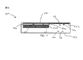
図5は、例示的実施形態に従った、少なくとも1つの統合された無線受信アンテナを有する電子デバイス500の簡略化された断面図を描いている。電子デバイス500は任意の電子デバイス、例えばあくまで例として携帯電話、携帯型メディア・プレイヤー、カメラ、ゲーム機、ナビゲーション装置、ヘッドセット(例えばBluetooth(登録商標)ヘッドセット)、ツール、玩具、あるいはそれらの任意の組合せ、を具備し得る。電子デバイス500は第1面510および第2面508を含んでおり得る。それらは金属フレームを含んでおり得る。さらに、電子デバイス500は、無線受信アンテナのループ導電体502を含んでいる。ループ導電体502は充電可能(chargeable)バッテリ504を無線充電するように構成されており、バッテリ504に動作可能に結合されており得る。バッテリ504は金属筐体を含んでおり得る。
FIG. 5 depicts a simplified cross-sectional view of an
図5に図示されているように、ループ導電体502は、第1面508および充電可能バッテリ504の各々と離されており、その間に隙間506を有している。本明細書において使用されている文言「隙間」は、空スペース、非導電性構成要素を具備するスペース、またはそれらの任意の組合せを具備し得る。図5に描かれている例において、隙間506の一部は、ループ導電体502と充電可能バッテリ504との間に位置する空スペース505を含んでいる。さらに、隙間506の別の部分はループ導電体502と第1面508との間に位置する空スペース511を含んでいる。したがって、隙間506は、ループ導電体502に関連しかつ隣接し得る磁界のための回避経路を提供し得る。具体的には、このように構成されている電子デバイス500は、ループ導電体502の全周囲(entirely around)に回避経路を提供し得る。上述のように、ループ導電体502に隣接する回避経路は、磁界がループ導電体502の周囲において存在することを可能にし、したがって関連する無線受信アンテナの機能が強化され得る。さらに、導電性構成要素(すなわち充電可能バッテリ504、第2面508、またはその両方)に起因するループ導電体502に隣接しかつ関連する磁界に対するあらゆる悪影響が制限され得る。
As illustrated in FIG. 5, the
無線受信アンテナは、無線受信アンテナのループ導電体502が、その統合時に、無線受信アンテナの減衰していないQ値が約4を超える因数で悪化するのを防ぐのに十分な距離で第1面508および充電可能バッテリ504の各々から離されるように電子デバイス500中に統合され得ることに注意されたい。別の言い方をすれば、無線受信アンテナの減衰していないQ値は、電子デバイス500中への統合時の無線受信アンテナのQ値の実質的に4倍を超えていないべきである。より具体的かつ非制限的な例として、ループ導電体502は、電子デバイス500中に統合され、充電可能バッテリ504から約1〜2ミリメートル離されており得る。
The wireless receive antenna is at a distance sufficient to prevent the
図6は、例示的実施形態に従った、少なくとも1つの統合された受信アンテナを有する別の電子デバイス600の簡略化された断面図を描いている。図5に描かれている電子デバイス500と同様に、電子デバイス600は、第1面610および第2面608を含んでいる。それらは金属フレームを含んでおり得る。さらに、電子デバイス500は、無線受信アンテナのループ導電体602を含んでいる。ループ導電体602は充電可能バッテリ604を無線充電するように構成されており、バッテリ604に動作可能に結合されており得る。バッテリ604は金属筐体を含んでおり得る。さらに、電子デバイス600は構成要素609を含んでいる。構成要素609は、ループ導電体602の一部に隣接し、非導電性材料から構成されている。
FIG. 6 depicts a simplified cross-sectional view of another
図6に図示されているように、ループ導電体602は充電可能バッテリ604から離されており、その間に隙間606が位置している。具体的には、隙間606の一部はループ導電体602と充電可能バッテリ604との間に位置する空スペース605を含んでいる。したがって、充電可能バッテリ604によって引き起こされるループ導電体602に隣接しかつ関連する磁界に対するあらゆる悪影響が制限され得る。
As illustrated in FIG. 6, the
また、隙間606の別の部分は構成要素609の一部を具備し得ることに注意されたい。上述のように、磁界が非導電性部分内および周囲に存在し得るので、構成要素609はループ導電体602に関連しかつ隣接する磁界に悪影響を及ぼさないかもしれない。したがって、隙間606は、ループ導電体に関連しかつ隣接し得る磁界のための回避経路を提供し得る。具体的には、このように構成されている電子デバイス600は、ループ導電体602の全周囲に回避経路を提供し得る。上述のように、ループ導電体602に隣接する回避経路は、磁界がループ導電体602の周囲において存在することを可能にし、したがって関連する無線受信アンテナの機能が強化され得る。
Also note that another portion of the gap 606 may comprise a portion of the component 609. As mentioned above, the component 609 may be associated with the
さらに、無線受信アンテナは、無線受信アンテナのループ導電体602が、その統合時に、無線受信アンテナの減衰していないQ値が約4を超える因数で悪化するのを防ぐのに十分な距離で充電可能バッテリ604から離されるように電子デバイス600中に統合され得ることに注意されたい。別の言い方をすれば、無線受信アンテナの減衰していないQ値は、電子デバイス600中への統合時の無線受信アンテナのQ値の実質的に4倍を越えていないべきである。より具体的かつ非制限的な例として、ループ導電体602は、電子デバイス600中に統合され、充電可能バッテリ604から約1〜2ミリメートル離されており得る。
In addition, the wireless receive antenna is charged at a distance sufficient to prevent the
図7は、例示的実施形態に従った、少なくとも1つの統合された受信アンテナを有する電子デバイス700のさらなる別の例の簡略化された断面図を描いている。上記の電子デバイス500および600と同様に、電子デバイス700は第1面710および第2面708を含んでいる。それらは金属フレームを含んでおり得る。さらに、電子デバイス700は、無線受信アンテナのループ導電体702を含んでいる。ループ導電体702は充電可能バッテリ704を無線充電するように構成されており、バッテリ704に動作可能に結合されており得る。バッテリ704は金属筐体を含んでおり得る。さらに、電子デバイス700は構成要素709を含んでいる。構成要素709は、ループ導電体702の一部に隣接し、非導電性材料から構成されている。
FIG. 7 depicts a simplified cross-sectional view of yet another example of an
図7に描かれているように、ループ導電体702は充電可能バッテリ704および第2面708から離されており、その間に隙間706が位置している。具体的には、隙間706の一部はループ導電体702と充電可能バッテリ704との間に位置する空スペース705を含んでいる。さらに、隙間706の別の部分は、ループ導電体702と第2面708との間に位置する空スペース711を含んでいる。その結果、充電可能バッテリ704、第2面708、または両方に起因する、ループ導電体702に隣接しかつ関連する磁界に対するあらゆる悪影響が制限され得る。
As depicted in FIG. 7, the
また、隙間706の別の部分は構成要素709の一部を具備し得ることに注意されたい。上述のように、磁界が非導電性部分内および周囲に存在し得るので、ループ導電体702に隣接しかつ関連する磁界は構成要素709によって悪影響を受けないかもしれない。したがって、隙間706は、ループ導電体702に関連しかつ隣接し得る磁界のための回避経路を提供し得る。上述のように、ループ導電体702に隣接する回避経路は、磁界がループ導電体702の周囲において存在することを可能にし、したがって関連する無線受信アンテナの機能が強化され得る。具体的には、このように構成されている電子デバイス700は、ループ導電体702の全周囲に回避経路を提供し得る。
Also, it should be noted that another portion of the
さらに、無線受信アンテナは、無線受信アンテナのループ導電体702が、その統合時に、無線受信アンテナの減衰していないQ値が約4を超える因数で悪化するのを防ぐのに十分な距離で第2面708および充電可能バッテリ704の各々から離されるように電子デバイス700中に統合され得ることに注意されたい。別の言い方をすれば、無線受信アンテナの減衰していないQ値は、電子デバイス700中への統合時の無線受信アンテナのQ値の実質的に4倍を越えていないべきである。 より具体的かつ非制限的な例として、ループ導電体702は電子デバイス700中に統合され、充電可能バッテリ704から約1〜2ミリメートル離されており得る。
In addition, the wireless receive antenna is at a distance sufficient to prevent the
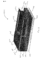
図8は、例示的実施形態に従った、少なくとも1つの統合された受信アンテナを有する電子デバイス570の断面図を図示している。電子デバイス570はディスプレイ装置574を含んでいる。ディスプレイ装置574は、キーボード(図示せず)およびディスプレイ領域を囲む金属フレームを具備し得る。電子デバイス570はまた、プリント回路基板578に隣接する電子モジュール576を含んでいる。それらは、各々導電性材料を含んでおり得る。また、電子デバイス570は、金属筐体を有するバッテリ580、および様々な導電性構成要素を含んでおり得るRF電子およびアンテナ・モジュール582を含んでいる。さらに、電子デバイス570は、金属筐体を有するカメラ584を含んでいる。
FIG. 8 illustrates a cross-sectional view of an electronic device 570 having at least one integrated receive antenna in accordance with an illustrative embodiment. Electronic device 570 includes a
図8に図示されているように、無線受信アンテナのループ導電体572は、無線充電するように構成されており得、ループ導電体572と電子デバイス570内の各導電性構成要素との間に位置する隙間586を含むように電子デバイス570内に統合されており得る。したがって、隙間586は、ループ導電体572に隣接して存在し得る磁界のための回避経路を提供し得る。上述のように、ループ導電体572に隣接する回避経路は、磁界がループ導電体572の周囲において存在することを可能にし、したがって関連する無線受信アンテナの機能を強化し得る。具体的には、このように構成されている電子デバイス570は、ループ導電体572の全周囲に回避経路を提供し得る。さらに、1つまたは複数の導電性構成要素によって引き起こされる、ループ導電体572に隣接しかつ関連するする磁界に対するあらゆる悪影響が制限され得る。
As illustrated in FIG. 8, the loop conductor 572 of the wireless receiving antenna may be configured to wirelessly charge, and between the loop conductor 572 and each conductive component in the electronic device 570. It may be integrated within electronic device 570 to include a
さらに、無線受信アンテナは、無線受信アンテナのループ導電体572が、その統合時に、無線受信アンテナの減衰していないQ値が約4を越える因数で悪化するのを防ぐのに十分な距離で電子デバイス570内の各導電性構成要素から離されるように電子デバイス570中に統合され得ることに注意されたい。別の言い方をすれば、無線受信アンテナの減衰していないQ値は、電子デバイス570中への統合時の無線受信アンテナのQ値の実質的に4倍を越えていないべきである。より具体的かつ非制限的な例として、ループ導電体572は、電子デバイス570中に統合され、各導電性構成要素から少なくとも約1〜2ミリメートル離されており得る。 In addition, the wireless receive antenna is electronic in sufficient distance to prevent the loop conductor 572 of the wireless receive antenna from aggravating the unattenuated Q of the wireless receive antenna by a factor of more than about 4 when integrated. It should be noted that it may be integrated into the electronic device 570 so as to be separated from each conductive component in the device 570. Stated differently, the unattenuated Q-factor of the wireless receive antenna should not exceed substantially four times the Q-factor of the wireless receive antenna upon integration into the electronic device 570. As a more specific and non-limiting example, the loop conductor 572 may be integrated into the electronic device 570 and separated from each conductive component by at least about 1-2 millimeters.
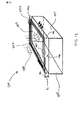
図9は、例示的実施形態に従った、少なくとも1つの統合された受信アンテナを有する別の電子デバイス670の断面図を図示している。電子デバイス670はディスプレイ装置674を含んでいる。ディスプレイ装置674は、キーボード(図示せず)およびディスプレイ領域を囲む金属フレームを具備し得る。電子デバイス670はまた、プリント回路基板678に隣接する電子モジュール676を含んでいる。それらは、各々導電性材料を含んでおり得る。また、電子デバイス570は、金属筐体を有するバッテリ580、および様々な導電性構成要素を含んでおり得るRF電子およびアンテナ・モジュール582を含んでいる。さらに、電子デバイス670は、金属筐体を有するカメラ684を含んでいる。さらに、電子デバイス670は構成要素688を含んでいる。構成要素688は無線受信アンテナ672に隣接し、非導電性材料から構成されている。
FIG. 9 illustrates a cross-sectional view of another electronic device 670 having at least one integrated receive antenna in accordance with an illustrative embodiment. Electronic device 670 includes a
図9に図示されているように、無線受信アンテナのループ導電体672は、無線充電するように構成されており、ループ導電体672と電子デバイス670内の各導電性構成要素との間に位置する隙間686を含むように電子デバイス670内に統合されており得る。別の言い方をすれば、ループ導電体672は、隙間686の一部によって電子デバイス670内の各導電性構成要素から離されている。その結果、電子デバイス670内の1つまたは複数の導電性構成要素によって引き起こされる、ループ導電体672に隣接しかつ関連する磁界に対するあらゆる悪影響が制限され得る。
As illustrated in FIG. 9, the loop conductor 672 of the wireless receiving antenna is configured to wirelessly charge and is positioned between the loop conductor 672 and each conductive component in the electronic device 670. Can be integrated into the electronic device 670 to include the
また、隙間686の別の部分は構成要素688の一部を具備し得ることに注意されたい。上記のように、磁界は非導電性構成要素内および周囲に存在し得、したがって、構成要素688はループ導電体672に隣接している磁界に悪影響を及ぼさないかもしれない。したがって、隙間686は、ループ導電体に関連しかつ隣接し得る磁界のための回避経路を提供し得る。具体的には、このように構成されている電子デバイス600は、ループ導電体670の全周囲に回避経路を提供し得る。上述のように、ループ導電体502に隣接する回避経路は、磁界がループ導電体502の周囲において存在することを可能にし、したがって関連する無線受信アンテナの機能を強化し得る。
Also note that another portion of the
さらに、無線受信アンテナは、無線受信アンテナのループ導電体672が、その統合時に、無線受信アンテナの減衰していないQ値が約4を超える因数で悪化するのを防ぐのに十分な距離で電子デバイス670内の各導電性構成要素から離されるように電子デバイス670中に統合され得ることに注意されたい。別の言い方をすれば、無線受信アンテナの減衰していないQ値は、電子デバイス570中への統合時の無線受信アンテナのQ値の実質的に4倍を越えていないべきである。より具体的かつ非制限的な例として、ループ導電体672は電子デバイス670中に統合され、各導電性構成要素から少なくとも約1〜2ミリメートル離され得る。 In addition, the wireless receive antenna is electronic in sufficient distance to prevent the loop conductor 672 of the wireless receive antenna from being degraded by a factor of about 4 or more when integrated with the wireless receive antenna. It should be noted that it may be integrated into the electronic device 670 so as to be separated from each conductive component in the device 670. Stated differently, the unattenuated Q-factor of the wireless receive antenna should not exceed substantially four times the Q-factor of the wireless receive antenna upon integration into the electronic device 570. As a more specific and non-limiting example, loop conductor 672 may be integrated into electronic device 670 and separated from each conductive component by at least about 1-2 millimeters.
図10は、例示的実施形態に従った、統合されかつ無線充電するように構成されている少なくとも1つの受信アンテナを有する電子デバイス800の簡略化された平面図を図示している。電子デバイス800は外面803を含んでおり得る。外面803は金属フレームを具備し得る。さらに、電子デバイス800は、無線受信アンテナのループ導電体802を含んでいる。ループ導電体802は充電可能バッテリ804に動作可能に結合されており得る。バッテリ804は金属筐体を含んでおり得る。図示されているように、ループ導電体802は電子デバイス800内に統合されており、隙間806によって充電可能バッテリ804および外面803の各々から離されている。例として、ループ導電体802は、電子デバイス800中に統合され、その統合時に、関連する無線受信アンテナの減衰していないQ値が約4を超える因数で悪化するのを防ぐのに十分な距離で外面803および充電可能バッテリ804の各々から離されており得る。別の言い方をすれば、無線受信アンテナの減衰していないQ値は、電子デバイス800中への統合時の無線受信アンテナのQ値の実質的に4倍を越えていないべきである。より具体的かつ非制限的例として、ループ導電体802は電子デバイス800中に統合され、充電可能バッテリ804および外面803から約1〜2ミリメートル以上、離されており得る。
FIG. 10 illustrates a simplified plan view of an
したがって、隙間806は、ループ導電体802に隣接しかつ関連し得る磁界のための回避経路を提供し得る。具体的には、このように構成されている電子デバイス800は、ループ導電体802の全周囲に回避経路を提供し得る。上述のように、ループ導電体802に隣接する回避経路は、磁界がループ導電体802の周囲において存在することを可能にし、したがって関連する無線受信アンテナの機能を強化し得る。また、外面803、充電可能バッテリ804、または両方によって引き起こされる、ループ導電体802に隣接しかつ関連する磁界に対するあらゆる悪影響が制限され得る。
Thus, the
図11は、例示的実施形態に従った、統合されかつ無線充電するように構成されている少なくとも1つの無線受信アンテナを有するさらに別の電子デバイス900の簡略化された平面図を描いている。上記の電子デバイス800と同様に、電子デバイス900は外面903を含んでおり得る。外面903は金属フレームを具備し得る。また、電子デバイス900は、無線受信アンテナのループ導電体902をさらに含んでいる。ループ導電体902は充電可能バッテリ904に動作可能に結合されており得る。バッテリ904は金属筐体を含んでおり得る。さらに、電子デバイス900は構成要素909を含んでいる。構成要素909は、ループ導電体902に隣接し、非導電性材料から構成されている。
FIG. 11 depicts a simplified plan view of yet another electronic device 900 having at least one wireless receive antenna configured to be integrated and wirelessly charged according to an illustrative embodiment. Similar to the
図11に図示されているように、ループ導電体902は電子デバイス900内に統合され、隙間906の一部によって外面903から離されており得る。したがって、外面903によって引き起こされる、ループ導電体902に隣接しかつ関連する磁界に対するあらゆる悪影響が制限され得る。例として、ループ導電体902は、電子デバイス900中に統合され、その統合時に、関連する無線受信アンテナに減衰していないQ値が約4を超える因数で悪化するのを防ぐのに十分な距離で外面903から離されており得る。別の言い方をすれば、無線受信アンテナの減衰していないQ値は、電子デバイス900中への統合時の無線受信アンテナのQ値の実質的に4倍を越えていないべきである。より具体的かつ非制限的な例として、ループ導電体902は電子デバイス900中に統合され、外面903から約1〜2ミリメートル離されており得る。
As illustrated in FIG. 11,
さらに、隙間906の別の部分は構成要素909の一部を具備し得ることに注意されたい。したがって、このように構成されている電子デバイス900は、ループ導電体902の全周囲に回避経路を提供し得る。上述のように、ループ導電体902に隣接する回避経路は、磁界がループ導電体902の周囲において存在することを可能にし、したがって関連する無線受信アンテナの機能を強化し得る。
Further, it should be noted that another portion of the
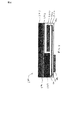
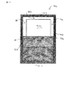
図12は、例示的な実施形態に従った、少なくとも1つの統合された受信アンテナを有する電子デバイス550についての様子を描いている。電子デバイス550はディスプレイ装置554を含んでいる。ディスプレイ装置554は、キーボード(図示せず)およびディスプレイ領域を囲む金属フレームを具備し得る。電子デバイス550はまた、プリント回路基板558に隣接する電子モジュール556を含んでいる。それらは、各々導電性材料を含んでおり得る。また、電子デバイス550は、金属筐体を有するバッテリ560、および様々な導電性構成要素を含んでおり得るRF電子およびアンテナ・モジュール562を含んでいる。さらに、電子デバイス550は、金属筐体を有するカメラ564を含んでいる。
FIG. 12 depicts an overview of an
図13は、電子デバイス550についての別の様子を図示している。図12および図13の各々に図示されているように、無線受信アンテナのループ導電体552は、電子デバイス550内の各導電性構成要素から物理的に離されている(すなわち、隙間が存在する)。具体的には、隙間は、ループ導電体552と、カメラ564、バッテリ560、およびRF電子およびアンテナ・モジュール562の各々との間に存在する。したがって、この間隔は、ループ導電体552に隣接して存在する磁界のための回避経路(矢印564によって図示されている)を提供し得る。このように構成されている電子デバイス550は、ループ導電体552の全周囲に回避経路を提供し得ることに注意されたい。上述のように、ループ導電体552に隣接する回避経路は、磁界がループ導電体552の周囲において存在することを可能にし、したがって関連する無線受信アンテナの機能が強化され得る。
FIG. 13 illustrates another aspect of the
例として、無線受信アンテナは、無線受信アンテナのループ導電体552が、その統合の際に、無線受信アンテナの減衰していないQ値が約4を超える因数で悪化するのを防ぐのに十分な距離で電子デバイス550内の各導電性構成要素から離されるように電子デバイス550中に統合され得る。別の言い方をすれば、無線受信アンテナの減衰していないQ値は、電子デバイス500中への統合時の無線受信アンテナのQ値の実質的に4倍を越えていないべきである。より具体的かつ非制限的な例として、ループ導電体552は電子デバイス500中に統合され、各導電性構成要素から約1〜2ミリメートル以上離され得る。
By way of example, the wireless receiving antenna is sufficient to prevent the
図14は、無線受信アンテナのループ導電体782および導電性構成要素784を含んだ電子デバイス780の簡略化された例示である。例えば、導電性構成要素784は、金属筐体を有する充電式電池を具備し得る。図14に図示されているように、ループ導電体782は、導電性構成要素784から、その間の隙間786を有する距離Lによって離されている。非制限的な例として、距離Lは約1〜2ミリメートルの範囲を有し得る。さらに、隙間786は、例えば、空スペース、非導電性構成要素、またはそれらの任意の組合せを含み得る。したがって、隙間786は、ループ導電体782に関連する磁界のための回避経路(矢印788によって描かれている)を提供し得る。その結果、ループ導電体782に隣接しかつ関連する磁界に対するあらゆる悪影響が制限され得る。
FIG. 14 is a simplified illustration of an
無線受信アンテナは、無線受信アンテナのループ導電体782が、その統合時に、無線受信アンテナの減衰していないQ値が約4を超える因数で悪化するのを防ぐのに十分な距離で導電性構成要素784から離されるように電子デバイス780中に統合され得ることに注意されたい。別の言い方をすれば、無線受信アンテナの減衰していないQ値は、電子デバイス780中への統合時の無線受信アンテナのQ値の実質的に4倍を越えていないべきである。
The wireless receive antenna is configured with a distance sufficient to prevent the
図15は、例示的実施形態に従った、方法のフローチャートを図示している。方法700は、本明細書において記述されている様々な構造によってサポートされる。方法700は、少なくとも1つの無線受信アンテナを電子デバイス中に統合するステップ702を含んでいる。方法700は、さらに、少なくとも1つのアンテナのループ導電体を電子デバイス内の各導電性構成要素から離すステップ704を含んでいる。
FIG. 15 illustrates a flow chart of a method according to an exemplary embodiment.
図15は、例示的な実施形態に従った、別の方法のフローチャートを図示している。方法705は、本明細書において記述されている様々な構造によってサポートされる。方法705は、電子デバイス内に統合されかつ電子デバイス内の各導電性構成要素から離されているループ導電体を有する少なくとも1つの受信アンテナにおいて無線電力を受け取るステップ706を含んでいる。方法705は、さらに、少なくとも1つの受信アンテナからそれに結合されている少なくとも1つの充電可能バッテリに電力を伝送するステップ708含んでいる。
FIG. 15 illustrates a flowchart of another method, in accordance with an illustrative embodiment.
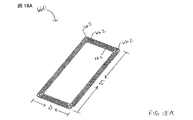
図17Aおよび図17Bは、例示的実施形態に従った、電子デバイス中への統合に向けて構成されている無線受信アンテナの1回巻きループ導体650を図示している。1回巻きループ導体650は、ワイヤまたはリボン652、例として銅線または銅製リボンを具備し得る。1つの例示的実施形態によれば、リボン652は、銀メッキを有する銅製リボンを具備し得る。さらに、図17Bに図示されているように、1回巻きループ導体650はキャパシタ654および端子656を含んでいる。図17Aを参照すると、非制限的な例として、1回巻きループ導体650は、約44.0ミリメートルの幅A、約89.0ミリメートルの高さBを有し得、リボン652は約3.0ミリメートルの幅Cを有し得る。さらに、1回巻きループ導体650は、リボン652の両端の間の間隔Fを有し得、間隔Fは単なる例として約1.0ミリメートルであり得る。間隔Fは、キャパシタ、例として図17Aに図示されているようなキャパシタ654、を配置するように構成されており得る。
17A and 17B illustrate a single
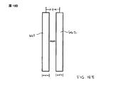
図18Aは、例示的実施形態に従った、電子デバイス中への統合に向けて構成されている無線受信アンテナの多巻きループ導電体660を図示している。図示されているように、多巻きループ導電体660は、複数のワイヤまたはリボン662具備し得る。ワイヤまたはリボン662の各々は、単なる例として銅を含み得る。さらに、非制限的な例として、多巻きループ導電体660は、約47ミリメートルの幅Dおよび約89ミリメートルの高さEを有し得る。また、図18Bに図示されているように、各ワイヤ662は幅Wを有し得、ワイヤ662同士は距離Xによって離されており得、隣接する配線662同士は中心・中心間距離Zを有し得る。「ルールオブサム(経験則、rules of thumb)」に従って、距離Xは、幅Wと実質的に等しく、中心・中心間距離Zは実質的に距離Xの値の2倍であり得る。単なる例として、幅Wおよび距離Xは各々約0.8ミリメートルであり得る。さらに、この例の場合、中心・中心間距離Zは約1.6ミリメートルであり得る。
FIG. 18A illustrates a
当業者は、制御情報および信号が様々な相違する科学的方法および技術のうちの任意のものを使用して表わされ得ることを理解するだろう。例えば、上記の記述の全体にわたって言及され得るデータ、命令、コマンド、情報、信号、ビット、シンボルおよびチップは、電圧、電流、電磁波、磁場または磁性粒子、光電場または光粒子、あるいはそれらの任意の組合せによって表わされ得る。 Those skilled in the art will appreciate that control information and signals may be represented using any of a variety of different scientific methods and techniques. For example, data, instructions, commands, information, signals, bits, symbols and chips that may be mentioned throughout the above description may be voltages, currents, electromagnetic waves, magnetic fields or particles, optical fields or particles, or any of them. It may be represented by a combination.
当業者は、さらに、本明細書において開示されている実施形態との関連で記述されている様々な例証用の論理ブロック、モジュール、回路、およびアルゴリズム・ステップが、電子回路ハードウェアとして実現され、コンピュータ・ソフトウェアによって制御され、または両方の組合せであり得ることを認識するであろう。このハードウェアとソフトウェアの互換性を明らかにするために、概して、様々な例証用の要素、ブロック、モジュール、回路、およびステップは、それらの機能の観点で上に記述された。そのような機能がハードウェアとしてまたはソフトウェアとして実現および制御されるかは、適用形態およびシステム全体に課されている具体的な設計制約に依存する。当業者は、記述されている機能を個々の具体的な適用形態向けの様々な形で実現し得、そのような実現形態を決定することは本発明の例示的実施形態の範囲からの逸脱を引き起こすものと解釈されるべきでない。 Those skilled in the art will further appreciate that the various illustrative logic blocks, modules, circuits, and algorithm steps described in the context of the embodiments disclosed herein are implemented as electronic circuit hardware. It will be appreciated that it may be controlled by computer software, or a combination of both. To illustrate this hardware and software compatibility, various illustrative elements, blocks, modules, circuits, and steps have been described above generally in terms of their functionality. Whether such functionality is implemented and controlled as hardware or software depends upon the application and specific design constraints imposed on the overall system. Those skilled in the art can realize the described functions in various ways for each specific application, and determining such an implementation deviates from the scope of the exemplary embodiments of the present invention. It should not be interpreted as causing.
本明細書において開示されている実施形態との関連で記述されている様々な例証用の論理ブロック、モジュール、回路は、汎用プロセッサ、ディジタル信号プロセッサ(DSP)、特定用途向けIC(ASIC)、フィールドプログラマブルゲートアレイ(FPGA)、または本明細書において記述されている機能を行なうように設計されている他のプログラム可能論理回路、ディスクリート型ゲートまたはトランジスタロジック、ディスクリート型ハードウェア構成機器またはそのあらゆる組合せによって制御され得る。汎用プロセッサはマイクロプロセッサであり得、または、汎用プロセッサは任意の従来のプロセッサ、コントローラ、マイクロコントローラ、あるいはステートマシンであり得る。プロセッサは、コンピュータ装置、例えばDSPとマイクロプロセッサの組合せ、複数のマイクロプロセッサ、DSPコアと協働する1つ以上のマイクロプロセッサ、または任意の他のそのような構成、の組合せとして実現され得る。 The various illustrative logic blocks, modules, circuits described in the context of the embodiments disclosed herein may be general purpose processors, digital signal processors (DSPs), application specific ICs (ASICs), fields. Programmable gate array (FPGA), or any other programmable logic circuit designed to perform the functions described herein, discrete gates or transistor logic, discrete hardware components, or any combination thereof It can be controlled. A general purpose processor may be a microprocessor, or a general purpose processor may be any conventional processor, controller, microcontroller, or state machine. The processor may be implemented as a combination of a computing device, such as a DSP and a microprocessor, a plurality of microprocessors, one or more microprocessors in cooperation with a DSP core, or any other such configuration.
本明細書において開示されている実施形態との関連において記述されている方法またはアルゴリズムの制御ステップは、ハードウェアで直接、プロセッサによって実行されるソフトウェア・モジュールで、またはこれら2つの組合せで具現さ得る。ソフトウェア・モジュールは、ランダム・アクセス・メモリ(RAM)、フラッシュ・メモリ、読み取り専用メモリ(ROM)、電気的プログラム可能ROM(EPROM)、電気的消去可能プログラマブルROM(EEPROM)、レジスタ、ハード・ディスク、取外し可能ディスク、CD−ROM、あるいは当技術において既知の記憶媒体のあらゆる他の形態内に存在し得る。例示的な記憶媒体は、プロセッサがこの記録媒体から情報を読み出し、この記録媒体に情報を書き込めるように、該プロセッサに接続されている。または、記憶媒体はプロセッサと一体化されていてもよい。プロセッサと記憶媒体はASIC内に存在していてもよい。ASICはユーザ端末内に存在し得る。または、プロセッサと記憶媒体はユーザ端末のディスクリート部品として存在し得る。 The control steps of a method or algorithm described in the context of the embodiments disclosed herein may be embodied directly in hardware, in a software module executed by a processor, or in a combination of the two. . The software modules include random access memory (RAM), flash memory, read only memory (ROM), electrically programmable ROM (EPROM), electrically erasable programmable ROM (EEPROM), registers, hard disk, It may reside in a removable disk, a CD-ROM, or any other form of storage medium known in the art. An exemplary storage medium is coupled to the processor such that the processor can read information from, and write information to, the storage medium. Alternatively, the storage medium may be integral to the processor. The processor and the storage medium may reside in an ASIC. The ASIC may reside in a user terminal. Alternatively, the processor and the storage medium may be present as discrete components of a user terminal.
1つまたは複数の例示的な実施形態において、記述されている制御機能は、ハードウェア、ソフトウェア、ファームウェア、またはそれらのあらゆる組合せにおいて実現され得る。ソフトウェアにおいて実現される場合、関数は1つまたは複数の指示またはコードとして、コンピュータ可読媒体上で格納または送信され得る。コンピュータ可読媒体は、コンピュータ記憶装置媒体、およびコンピュータ・プログラムのある位置から別の位置への移動を容易にするあらゆる媒体を含む通信媒体、の両方を含んでいる。記憶媒体は、コンピュータによってアクセスされることが可能なあらゆる利用可能な物理的媒体であり得る。限定ではなく例として、そのようなコンピュータ可読媒体は、RAM、ROM、EEPROM、CD−ROMまたは他の光学ディスク記憶装置、磁気ディスク記憶装置または他の磁気記憶装置、または命令またはデータ構造の形態の所望のプログラム・コードを運ぶか格納するために使用されることが可能で且つコンピュータによってアクセスされることが可能な他のあらゆる媒体を具備し得る。また、あらゆる接続も当然、コンピュータ可読媒体と称される。例えば、ソフトウェアが、同軸ケーブル、光ファイバーケーブル、撚線対、ディジタル加入者線(DSL)、または赤外線、無線およびマイクロ波のような無線技術を使用して、ウェブサイト、サーバ、または他の遠隔ソースから送信される場合、この同軸ケーブル、光ファイバーケーブル、撚線対、DSL、または赤外線、無線およびマイクロ波のような無線技術は、媒体の定義に含まれている。本明細書において使用されているディスク(disk)とディスク(disc)は、コンパクト・ディスク(CD)、レーザーディスク(登録商標)、光ディスク、ディジタル多用途ディスク(DVD)、フロッピー(登録商標)・ディスクおよびブルーレイ・ディスクを含んでいる。ここで、ディスク(disk)は通常磁気的にデータを再生し、他方、ディスク(disc)はレーザーでデータを光学的に再生する。上記のものの組合せもコンピュータ可読媒体の範囲内に含まれるべきである。 In one or more exemplary embodiments, the control functions described may be implemented in hardware, software, firmware, or any combination thereof. When implemented in software, the function may be stored or transmitted as one or more instructions or code on a computer readable medium. Computer-readable media includes both computer storage media and communication media including any medium that facilitates transfer of a computer program from one place to another. A storage media may be any available physical media that can be accessed by a computer. By way of example and not limitation, such computer readable media may be in the form of RAM, ROM, EEPROM, CD-ROM or other optical disk storage, magnetic disk storage or other magnetic storage, or instructions or data structures. It may comprise any other medium that can be used to carry or store the desired program code and can be accessed by a computer. Also, of course, any connection is termed a computer-readable medium. For example, software may use a coaxial cable, fiber optic cable, twisted pair, digital subscriber line (DSL), or wireless technology such as infrared, radio and microwave, a website, server or other remote source If transmitted from this, this coaxial cable, fiber optic cable, twisted pair, DSL, or wireless technologies such as infrared, radio and microwave are included in the definition of medium. The disks and discs used in the present specification are compact disks (CDs), laser disks (registered trademark), optical disks, digital versatile disks (DVDs), floppy disks And Blu-ray Disc included. Here, the disc normally reproduces data magnetically, while the disc optically reproduces data with a laser. Combinations of the above should also be included within the scope of computer readable media.
上に開示されている例示的実施形態の記述は、あらゆる当業者が本発明を実行または使用することを可能にするために提供されている。これらの例示的実施形態に対する様々な修正は当業者にとって容易に明らかになり、また、本明細書において定義されている包括的な原理は、発明の思想または範囲から逸脱することなく他の実施形態に適用され得る。 The description of the exemplary embodiments disclosed above is provided to enable any person skilled in the art to make or use the present invention. Various modifications to these exemplary embodiments will be readily apparent to those skilled in the art, and the generic principles defined herein are other embodiments without departing from the spirit or scope of the invention. Can be applied to
したがって、本発明は、本明細書において示されている実施形態に制限されることを意図されておらず、本明細書において開示されている原理および新規な特徴と一貫している最も広い範囲と一致するべきである。 Thus, the present invention is not intended to be limited to the embodiments shown herein but is to be accorded the widest scope consistent with the principles and novel features disclosed herein. Should match.
Claims (26)
前記少なくとも1つの受信アンテナのループ導電体は前記電子デバイス内の各導電性構成要素から離されて構成されており、その間に、前記ループ導電体の周囲での磁界の形成を可能にするように適合されている隙間を有する、電子デバイス。 Comprising at least one receive antenna integrated in the electronic device and configured to receive wireless power from the wireless transmit antenna;
The loop conductor of the at least one receiving antenna is configured to be separated from each conductive component in the electronic device, so as to enable the formation of a magnetic field around the loop conductor therebetween Electronic device having a gap that is adapted.
請求項1の電子デバイス。 The loop conductor of the at least one receive antenna comprises one of a single turn loop conductor and a multiple turn loop conductor.
The electronic device of claim 1.
請求項1の電子デバイス。 The loop conductor of the at least one receive antenna being configured apart from a chargeable battery in the electronic device;
The electronic device of claim 1.
請求項1の電子デバイス。 The loop conductor of the at least one receive antenna is adjacent to a nonconductive component,
The electronic device of claim 1.
請求項1の電子デバイス。 The gap comprises an empty space, a non-conductive component, or any combination thereof.
The electronic device of claim 1.
請求項1の電子デバイス。 The loop conductor of the at least one receive antenna is sufficient to prevent the Q factor of the associated wireless receive antenna from being degraded by a factor of more than about 4 upon integration of the wireless receive antenna into the electronic device. Separated from each conductive component by a distance,
The electronic device of claim 1.
請求項1の電子デバイス。 The loop conductors of the at least one wireless receiving antenna are each at a distance sufficient to degrade the Q factor of the associated wireless receiving antenna by at least a factor of about 2 upon integration of the wireless receiving antenna into the electronic device. Separated from the conductive component,
The electronic device of claim 1.
請求項1の電子デバイス。 The loop conductor of the at least one wireless receiving antenna causes the Q factor of the associated wireless receiving antenna to deteriorate by a factor of at least about a factor of 2 and less than a factor of 4 when integrating the wireless receiving antenna into the electronic device. Separated from each conductive component by a sufficient distance
The electronic device of claim 1.
請求項1の電子デバイス。 The loop conductors of the at least one receive antenna are spaced apart from each conductive component by at least about 1-2 millimeters.
The electronic device of claim 1.
前記少なくとも1つの受信アンテナのループ導電体は、前記ループ導電体と関連する磁界がループ導電体の全周囲において存在することを可能にするようにデバイス内に位置するように構成されている、装置。 Comprising at least one wireless receive antenna configured to receive wireless power from the wireless transmit antenna;
The apparatus wherein the loop conductor of the at least one receive antenna is configured to be located in a device to allow a magnetic field associated with the loop conductor to be present all around the loop conductor. .
請求項10の装置。 The loop conductor is configured to be located near the non-conductive component,
The device of claim 10.
請求項11の装置。 The magnetic field is present in the non-conductive component,
The device of claim 11.
請求項10の装置。 The loop conductor is configured to be separated from each conductive component, with at least a portion of a gap therebetween
The device of claim 10.
前記少なくとも1つのアンテナのループ導電体の周囲での磁界の形成を可能にすることと、
を具備する、電子デバイス中に受信アンテナを統合する方法。 Integrating at least one wireless receiving antenna into the electronic device;
Enabling the formation of a magnetic field around the loop conductor of the at least one antenna;
A method of integrating a receiving antenna into an electronic device, comprising:
請求項14の方法。 Allowing a magnetic field to be present around the loop conductor of the at least one antenna comprises separating the loop conductor from each conductive component in the electronic device,
The method of claim 14.
請求項15の方法。 Releasing the loop conductor prevents the loop conductor from degrading the Q factor of the associated wireless receive antenna by a factor of more than about 4 upon integration of the associated wireless receive antenna into the electronic device Separate from each conductive component in the electronic device by a sufficient distance
The method of claim 15.
請求項14の方法。 Further comprising positioning a non-conductive component adjacent to the loop conductor,
The method of claim 14.
請求項14の方法。 Separating the at least one loop conductor from each conductive component in the electronic device comprises separating the loop conductor from the rechargeable battery at a distance of about 1-2 millimeters therebetween.
The method of claim 14.
請求項14の方法。 Allowing the formation of a magnetic field adjacent to the loop conductor comprises allowing the formation of a magnetic field all around the loop conductor,
The method of claim 14.
前記少なくとも1つの受信アンテナからそれに結合されている少なくとも1つの充電可能バッテリに電力を伝送することと、
を具備する、電子デバイスを充電する方法。 Receiving wireless power at at least one receive antenna having a loop conductor integrated into the electronic device and separated from each conductive component in the electronic device;
Transmitting power from the at least one receive antenna to at least one rechargeable battery coupled thereto;
A method of charging an electronic device.
請求項20の方法。 Receiving wireless power at at least one receive antenna having a loop conductor degrades the Q value of the associated wireless receive antenna by a factor of more than about 4 upon integration of the associated wireless receive antenna into the electronic device Receiving wireless power at at least one receive antenna having a loop conductor separated from each conductive component to prevent
21. The method of claim 20.
前記少なくとも1つの受信アンテナからそれに結合されている少なくとも1つの充電可能バッテリに電力を伝送するための手段と、
を具備する、充電可能デバイスの充電を促進する方法。 Means for receiving wireless power at at least one receive antenna having a loop conductor integrated within the electronic device and separated from each conductive component within the electronic device;
Means for transferring power from the at least one receive antenna to at least one rechargeable battery coupled thereto;
A method of facilitating charging of a rechargeable device, comprising:
前記少なくとも1つの無線受信アンテナは、さらに、磁界が前記少なくとも1つの無線受信アンテナのループ導電体の周囲において存在することを可能にするように電子デバイス中での統合に向けて構成されている、システム。 Comprising at least one wireless receive antenna configured to receive wireless power from the wireless transmit antenna;
The at least one wireless receiving antenna is further configured for integration in an electronic device to allow a magnetic field to be present around a loop conductor of the at least one wireless receiving antenna. system.
請求項23のシステム。 The loop conductor of at least one wireless receiving antenna is located near at least one non-conductive component of the electronic device,
The system of claim 23.
請求項23のシステム。 The loop conductor of the at least one wireless receiving antenna is spaced approximately 1-2 millimeters from the nearest conductive component.
The system of claim 23.
請求項23のシステム。 The at least one wireless receiving antenna is further configured for integration in the electronic device to enable formation of a magnetic field around the entire loop conductor.
The system of claim 23.
Applications Claiming Priority (5)
| Application Number | Priority Date | Filing Date | Title |
|---|---|---|---|
| US9526408P | 2008-09-08 | 2008-09-08 | |
| US61/095,264 | 2008-09-08 | ||
| US12/554,478 | 2009-09-04 | ||
| US12/554,478 US8581542B2 (en) | 2008-09-08 | 2009-09-04 | Receive antenna arrangement for wireless power |
| PCT/US2009/056242 WO2010028375A1 (en) | 2008-09-08 | 2009-09-08 | Receive antenna arrangement for wireless power |
Related Child Applications (1)
| Application Number | Title | Priority Date | Filing Date |
|---|---|---|---|
| JP2014146946A Division JP6138733B2 (en) | 2008-09-08 | 2014-07-17 | Receiver antenna placement for wireless power |
Publications (2)
| Publication Number | Publication Date |
|---|---|
| JP2012502613A true JP2012502613A (en) | 2012-01-26 |
| JP2012502613A5 JP2012502613A5 (en) | 2014-01-16 |
Family
ID=41210494
Family Applications (2)
| Application Number | Title | Priority Date | Filing Date |
|---|---|---|---|
| JP2011526275A Withdrawn JP2012502613A (en) | 2008-09-08 | 2009-09-08 | Receive antenna placement for wireless power |
| JP2014146946A Active JP6138733B2 (en) | 2008-09-08 | 2014-07-17 | Receiver antenna placement for wireless power |
Family Applications After (1)
| Application Number | Title | Priority Date | Filing Date |
|---|---|---|---|
| JP2014146946A Active JP6138733B2 (en) | 2008-09-08 | 2014-07-17 | Receiver antenna placement for wireless power |
Country Status (6)
| Country | Link |
|---|---|
| US (1) | US8581542B2 (en) |
| EP (1) | EP2342778A1 (en) |
| JP (2) | JP2012502613A (en) |
| KR (1) | KR101290381B1 (en) |
| CN (1) | CN102292868B (en) |
| WO (1) | WO2010028375A1 (en) |
Cited By (4)
| Publication number | Priority date | Publication date | Assignee | Title |
|---|---|---|---|---|
| JP2011217496A (en) * | 2010-03-31 | 2011-10-27 | Nagano Japan Radio Co | Antenna device for noncontact power transmission, power transmitter, power receiving apparatus, and noncontact power transmission system |
| JP2017524324A (en) * | 2014-07-07 | 2017-08-24 | クアルコム,インコーポレイテッド | Wireless power transfer through metal objects |
| JP2017527251A (en) * | 2014-09-05 | 2017-09-14 | クアルコム,インコーポレイテッド | Wireless charging of electronic devices with metal back |
| JP2017201880A (en) * | 2009-02-13 | 2017-11-09 | ウィトリシティ コーポレーション | Wireless energy transmission in lossy environment |
Families Citing this family (306)
| Publication number | Priority date | Publication date | Assignee | Title |
|---|---|---|---|---|
| US7825543B2 (en) | 2005-07-12 | 2010-11-02 | Massachusetts Institute Of Technology | Wireless energy transfer |
| US8115448B2 (en) | 2007-06-01 | 2012-02-14 | Michael Sasha John | Systems and methods for wireless power |
| US9421388B2 (en) | 2007-06-01 | 2016-08-23 | Witricity Corporation | Power generation for implantable devices |
| EP2281322B1 (en) | 2008-05-14 | 2016-03-23 | Massachusetts Institute of Technology | Wireless energy transfer, including interference enhancement |
| US8629578B2 (en) | 2008-09-27 | 2014-01-14 | Witricity Corporation | Wireless energy transfer systems |
| EP3544196B1 (en) | 2008-09-27 | 2023-09-13 | WiTricity Corporation | Wireless energy transfer systems |
| US8471410B2 (en) | 2008-09-27 | 2013-06-25 | Witricity Corporation | Wireless energy transfer over distance using field shaping to improve the coupling factor |
| US8901778B2 (en) | 2008-09-27 | 2014-12-02 | Witricity Corporation | Wireless energy transfer with variable size resonators for implanted medical devices |
| US8643326B2 (en) | 2008-09-27 | 2014-02-04 | Witricity Corporation | Tunable wireless energy transfer systems |
| US8487480B1 (en) | 2008-09-27 | 2013-07-16 | Witricity Corporation | Wireless energy transfer resonator kit |
| US8466583B2 (en) | 2008-09-27 | 2013-06-18 | Witricity Corporation | Tunable wireless energy transfer for outdoor lighting applications |
| US8901779B2 (en) | 2008-09-27 | 2014-12-02 | Witricity Corporation | Wireless energy transfer with resonator arrays for medical applications |
| US8441154B2 (en) | 2008-09-27 | 2013-05-14 | Witricity Corporation | Multi-resonator wireless energy transfer for exterior lighting |
| US9544683B2 (en) | 2008-09-27 | 2017-01-10 | Witricity Corporation | Wirelessly powered audio devices |
| US9105959B2 (en) | 2008-09-27 | 2015-08-11 | Witricity Corporation | Resonator enclosure |
| US9601261B2 (en) | 2008-09-27 | 2017-03-21 | Witricity Corporation | Wireless energy transfer using repeater resonators |
| US8497601B2 (en) | 2008-09-27 | 2013-07-30 | Witricity Corporation | Wireless energy transfer converters |
| US8304935B2 (en) | 2008-09-27 | 2012-11-06 | Witricity Corporation | Wireless energy transfer using field shaping to reduce loss |
| US8587153B2 (en) | 2008-09-27 | 2013-11-19 | Witricity Corporation | Wireless energy transfer using high Q resonators for lighting applications |
| US9601270B2 (en) | 2008-09-27 | 2017-03-21 | Witricity Corporation | Low AC resistance conductor designs |
| US8552592B2 (en) | 2008-09-27 | 2013-10-08 | Witricity Corporation | Wireless energy transfer with feedback control for lighting applications |
| US9744858B2 (en) | 2008-09-27 | 2017-08-29 | Witricity Corporation | System for wireless energy distribution in a vehicle |
| US8947186B2 (en) | 2008-09-27 | 2015-02-03 | Witricity Corporation | Wireless energy transfer resonator thermal management |
| US8912687B2 (en) | 2008-09-27 | 2014-12-16 | Witricity Corporation | Secure wireless energy transfer for vehicle applications |
| US8461721B2 (en) | 2008-09-27 | 2013-06-11 | Witricity Corporation | Wireless energy transfer using object positioning for low loss |
| US9035499B2 (en) | 2008-09-27 | 2015-05-19 | Witricity Corporation | Wireless energy transfer for photovoltaic panels |
| US8482158B2 (en) | 2008-09-27 | 2013-07-09 | Witricity Corporation | Wireless energy transfer using variable size resonators and system monitoring |
| US9246336B2 (en) | 2008-09-27 | 2016-01-26 | Witricity Corporation | Resonator optimizations for wireless energy transfer |
| US8669676B2 (en) | 2008-09-27 | 2014-03-11 | Witricity Corporation | Wireless energy transfer across variable distances using field shaping with magnetic materials to improve the coupling factor |
| US8963488B2 (en) | 2008-09-27 | 2015-02-24 | Witricity Corporation | Position insensitive wireless charging |
| US8772973B2 (en) | 2008-09-27 | 2014-07-08 | Witricity Corporation | Integrated resonator-shield structures |
| US8686598B2 (en) | 2008-09-27 | 2014-04-01 | Witricity Corporation | Wireless energy transfer for supplying power and heat to a device |
| US9318922B2 (en) | 2008-09-27 | 2016-04-19 | Witricity Corporation | Mechanically removable wireless power vehicle seat assembly |
| US9065423B2 (en) | 2008-09-27 | 2015-06-23 | Witricity Corporation | Wireless energy distribution system |
| US9106203B2 (en) | 2008-09-27 | 2015-08-11 | Witricity Corporation | Secure wireless energy transfer in medical applications |
| US8928276B2 (en) | 2008-09-27 | 2015-01-06 | Witricity Corporation | Integrated repeaters for cell phone applications |
| US8461722B2 (en) | 2008-09-27 | 2013-06-11 | Witricity Corporation | Wireless energy transfer using conducting surfaces to shape field and improve K |
| US8922066B2 (en) | 2008-09-27 | 2014-12-30 | Witricity Corporation | Wireless energy transfer with multi resonator arrays for vehicle applications |
| US8957549B2 (en) | 2008-09-27 | 2015-02-17 | Witricity Corporation | Tunable wireless energy transfer for in-vehicle applications |
| US8410636B2 (en) | 2008-09-27 | 2013-04-02 | Witricity Corporation | Low AC resistance conductor designs |
| US9093853B2 (en) | 2008-09-27 | 2015-07-28 | Witricity Corporation | Flexible resonator attachment |
| US9184595B2 (en) | 2008-09-27 | 2015-11-10 | Witricity Corporation | Wireless energy transfer in lossy environments |
| US8933594B2 (en) | 2008-09-27 | 2015-01-13 | Witricity Corporation | Wireless energy transfer for vehicles |
| US8587155B2 (en) | 2008-09-27 | 2013-11-19 | Witricity Corporation | Wireless energy transfer using repeater resonators |
| US8907531B2 (en) | 2008-09-27 | 2014-12-09 | Witricity Corporation | Wireless energy transfer with variable size resonators for medical applications |
| US8692412B2 (en) | 2008-09-27 | 2014-04-08 | Witricity Corporation | Temperature compensation in a wireless transfer system |
| US9515494B2 (en) | 2008-09-27 | 2016-12-06 | Witricity Corporation | Wireless power system including impedance matching network |
| US8937408B2 (en) | 2008-09-27 | 2015-01-20 | Witricity Corporation | Wireless energy transfer for medical applications |
| US8946938B2 (en) | 2008-09-27 | 2015-02-03 | Witricity Corporation | Safety systems for wireless energy transfer in vehicle applications |
| US8400017B2 (en) | 2008-09-27 | 2013-03-19 | Witricity Corporation | Wireless energy transfer for computer peripheral applications |
| US8461720B2 (en) | 2008-09-27 | 2013-06-11 | Witricity Corporation | Wireless energy transfer using conducting surfaces to shape fields and reduce loss |
| US9160203B2 (en) | 2008-09-27 | 2015-10-13 | Witricity Corporation | Wireless powered television |
| US9601266B2 (en) | 2008-09-27 | 2017-03-21 | Witricity Corporation | Multiple connected resonators with a single electronic circuit |
| US8324759B2 (en) | 2008-09-27 | 2012-12-04 | Witricity Corporation | Wireless energy transfer using magnetic materials to shape field and reduce loss |
| US8598743B2 (en) | 2008-09-27 | 2013-12-03 | Witricity Corporation | Resonator arrays for wireless energy transfer |
| US9577436B2 (en) | 2008-09-27 | 2017-02-21 | Witricity Corporation | Wireless energy transfer for implantable devices |
| US9396867B2 (en) | 2008-09-27 | 2016-07-19 | Witricity Corporation | Integrated resonator-shield structures |
| US8476788B2 (en) | 2008-09-27 | 2013-07-02 | Witricity Corporation | Wireless energy transfer with high-Q resonators using field shaping to improve K |
| US8569914B2 (en) | 2008-09-27 | 2013-10-29 | Witricity Corporation | Wireless energy transfer using object positioning for improved k |
| US8692410B2 (en) | 2008-09-27 | 2014-04-08 | Witricity Corporation | Wireless energy transfer with frequency hopping |
| US8723366B2 (en) | 2008-09-27 | 2014-05-13 | Witricity Corporation | Wireless energy transfer resonator enclosures |
| US8362651B2 (en) | 2008-10-01 | 2013-01-29 | Massachusetts Institute Of Technology | Efficient near-field wireless energy transfer using adiabatic system variations |
| US11630366B2 (en) | 2009-12-22 | 2023-04-18 | View, Inc. | Window antennas for emitting radio frequency signals |
| US20130271813A1 (en) | 2012-04-17 | 2013-10-17 | View, Inc. | Controller for optically-switchable windows |
| US11732527B2 (en) | 2009-12-22 | 2023-08-22 | View, Inc. | Wirelessly powered and powering electrochromic windows |
| KR101142096B1 (en) * | 2010-08-02 | 2012-05-03 | 주식회사 네오펄스 | Harmonic emission prevented wireless power supply |
| US9602168B2 (en) | 2010-08-31 | 2017-03-21 | Witricity Corporation | Communication in wireless energy transfer systems |
| US8901775B2 (en) | 2010-12-10 | 2014-12-02 | Everheart Systems, Inc. | Implantable wireless power system |
| US9496924B2 (en) | 2010-12-10 | 2016-11-15 | Everheart Systems, Inc. | Mobile wireless power system |
| US9948145B2 (en) | 2011-07-08 | 2018-04-17 | Witricity Corporation | Wireless power transfer for a seat-vest-helmet system |
| US9384885B2 (en) | 2011-08-04 | 2016-07-05 | Witricity Corporation | Tunable wireless power architectures |
| WO2013036947A2 (en) | 2011-09-09 | 2013-03-14 | Witricity Corporation | Foreign object detection in wireless energy transfer systems |
| US20130062966A1 (en) | 2011-09-12 | 2013-03-14 | Witricity Corporation | Reconfigurable control architectures and algorithms for electric vehicle wireless energy transfer systems |
| US9479227B2 (en) | 2011-09-13 | 2016-10-25 | Samsung Electronics Co., Ltd. | Wireless electromagnetic receiver and wireless power transfer system |
| US9318257B2 (en) | 2011-10-18 | 2016-04-19 | Witricity Corporation | Wireless energy transfer for packaging |
| CN103988391A (en) | 2011-11-04 | 2014-08-13 | WiTricity公司 | Wireless energy transfer modeling tool |
| US9079043B2 (en) | 2011-11-21 | 2015-07-14 | Thoratec Corporation | Transcutaneous power transmission utilizing non-planar resonators |
| JP2015508987A (en) | 2012-01-26 | 2015-03-23 | ワイトリシティ コーポレーションWitricity Corporation | Wireless energy transmission with reduced field |
| US8933589B2 (en) | 2012-02-07 | 2015-01-13 | The Gillette Company | Wireless power transfer using separately tunable resonators |
| US11300848B2 (en) | 2015-10-06 | 2022-04-12 | View, Inc. | Controllers for optically-switchable devices |
| US9343922B2 (en) | 2012-06-27 | 2016-05-17 | Witricity Corporation | Wireless energy transfer for rechargeable batteries |
| US10008889B2 (en) | 2014-08-21 | 2018-06-26 | Energous Corporation | Method for automatically testing the operational status of a wireless power receiver in a wireless power transmission system |
| US9899873B2 (en) | 2014-05-23 | 2018-02-20 | Energous Corporation | System and method for generating a power receiver identifier in a wireless power network |
| US9893554B2 (en) | 2014-07-14 | 2018-02-13 | Energous Corporation | System and method for providing health safety in a wireless power transmission system |
| US9867062B1 (en) | 2014-07-21 | 2018-01-09 | Energous Corporation | System and methods for using a remote server to authorize a receiving device that has requested wireless power and to determine whether another receiving device should request wireless power in a wireless power transmission system |
| US9966765B1 (en) | 2013-06-25 | 2018-05-08 | Energous Corporation | Multi-mode transmitter |
| US10090886B1 (en) | 2014-07-14 | 2018-10-02 | Energous Corporation | System and method for enabling automatic charging schedules in a wireless power network to one or more devices |
| US9812890B1 (en) | 2013-07-11 | 2017-11-07 | Energous Corporation | Portable wireless charging pad |
| US10256657B2 (en) | 2015-12-24 | 2019-04-09 | Energous Corporation | Antenna having coaxial structure for near field wireless power charging |
| US9893555B1 (en) | 2013-10-10 | 2018-02-13 | Energous Corporation | Wireless charging of tools using a toolbox transmitter |
| US9876394B1 (en) | 2014-05-07 | 2018-01-23 | Energous Corporation | Boost-charger-boost system for enhanced power delivery |
| US10206185B2 (en) | 2013-05-10 | 2019-02-12 | Energous Corporation | System and methods for wireless power transmission to an electronic device in accordance with user-defined restrictions |
| US9893768B2 (en) | 2012-07-06 | 2018-02-13 | Energous Corporation | Methodology for multiple pocket-forming |
| US9252628B2 (en) | 2013-05-10 | 2016-02-02 | Energous Corporation | Laptop computer as a transmitter for wireless charging |
| US10965164B2 (en) | 2012-07-06 | 2021-03-30 | Energous Corporation | Systems and methods of wirelessly delivering power to a receiver device |
| US20140008993A1 (en) | 2012-07-06 | 2014-01-09 | DvineWave Inc. | Methodology for pocket-forming |
| US10063105B2 (en) | 2013-07-11 | 2018-08-28 | Energous Corporation | Proximity transmitters for wireless power charging systems |
| US10291055B1 (en) | 2014-12-29 | 2019-05-14 | Energous Corporation | Systems and methods for controlling far-field wireless power transmission based on battery power levels of a receiving device |
| US20150326070A1 (en) | 2014-05-07 | 2015-11-12 | Energous Corporation | Methods and Systems for Maximum Power Point Transfer in Receivers |
| US9882427B2 (en) | 2013-05-10 | 2018-01-30 | Energous Corporation | Wireless power delivery using a base station to control operations of a plurality of wireless power transmitters |
| US9438045B1 (en) | 2013-05-10 | 2016-09-06 | Energous Corporation | Methods and systems for maximum power point transfer in receivers |
| US10063064B1 (en) | 2014-05-23 | 2018-08-28 | Energous Corporation | System and method for generating a power receiver identifier in a wireless power network |
| US9847679B2 (en) | 2014-05-07 | 2017-12-19 | Energous Corporation | System and method for controlling communication between wireless power transmitter managers |
| US10141791B2 (en) | 2014-05-07 | 2018-11-27 | Energous Corporation | Systems and methods for controlling communications during wireless transmission of power using application programming interfaces |
| US9876648B2 (en) | 2014-08-21 | 2018-01-23 | Energous Corporation | System and method to control a wireless power transmission system by configuration of wireless power transmission control parameters |
| US10291066B1 (en) | 2014-05-07 | 2019-05-14 | Energous Corporation | Power transmission control systems and methods |
| US10224982B1 (en) | 2013-07-11 | 2019-03-05 | Energous Corporation | Wireless power transmitters for transmitting wireless power and tracking whether wireless power receivers are within authorized locations |
| US9847677B1 (en) | 2013-10-10 | 2017-12-19 | Energous Corporation | Wireless charging and powering of healthcare gadgets and sensors |
| US10992187B2 (en) | 2012-07-06 | 2021-04-27 | Energous Corporation | System and methods of using electromagnetic waves to wirelessly deliver power to electronic devices |
| US10211682B2 (en) | 2014-05-07 | 2019-02-19 | Energous Corporation | Systems and methods for controlling operation of a transmitter of a wireless power network based on user instructions received from an authenticated computing device powered or charged by a receiver of the wireless power network |
| US10218227B2 (en) | 2014-05-07 | 2019-02-26 | Energous Corporation | Compact PIFA antenna |
| US9991741B1 (en) | 2014-07-14 | 2018-06-05 | Energous Corporation | System for tracking and reporting status and usage information in a wireless power management system |
| US9853458B1 (en) | 2014-05-07 | 2017-12-26 | Energous Corporation | Systems and methods for device and power receiver pairing |
| US10223717B1 (en) | 2014-05-23 | 2019-03-05 | Energous Corporation | Systems and methods for payment-based authorization of wireless power transmission service |
| US10128693B2 (en) | 2014-07-14 | 2018-11-13 | Energous Corporation | System and method for providing health safety in a wireless power transmission system |
| US10193396B1 (en) | 2014-05-07 | 2019-01-29 | Energous Corporation | Cluster management of transmitters in a wireless power transmission system |
| US10263432B1 (en) | 2013-06-25 | 2019-04-16 | Energous Corporation | Multi-mode transmitter with an antenna array for delivering wireless power and providing Wi-Fi access |
| US10243414B1 (en) | 2014-05-07 | 2019-03-26 | Energous Corporation | Wearable device with wireless power and payload receiver |
| US10439448B2 (en) | 2014-08-21 | 2019-10-08 | Energous Corporation | Systems and methods for automatically testing the communication between wireless power transmitter and wireless power receiver |
| US10148097B1 (en) | 2013-11-08 | 2018-12-04 | Energous Corporation | Systems and methods for using a predetermined number of communication channels of a wireless power transmitter to communicate with different wireless power receivers |
| US9859797B1 (en) | 2014-05-07 | 2018-01-02 | Energous Corporation | Synchronous rectifier design for wireless power receiver |
| US9912199B2 (en) | 2012-07-06 | 2018-03-06 | Energous Corporation | Receivers for wireless power transmission |
| US10103582B2 (en) | 2012-07-06 | 2018-10-16 | Energous Corporation | Transmitters for wireless power transmission |
| US9825674B1 (en) | 2014-05-23 | 2017-11-21 | Energous Corporation | Enhanced transmitter that selects configurations of antenna elements for performing wireless power transmission and receiving functions |
| US9831718B2 (en) | 2013-07-25 | 2017-11-28 | Energous Corporation | TV with integrated wireless power transmitter |
| US10992185B2 (en) | 2012-07-06 | 2021-04-27 | Energous Corporation | Systems and methods of using electromagnetic waves to wirelessly deliver power to game controllers |
| US9948135B2 (en) | 2015-09-22 | 2018-04-17 | Energous Corporation | Systems and methods for identifying sensitive objects in a wireless charging transmission field |
| US9843213B2 (en) | 2013-08-06 | 2017-12-12 | Energous Corporation | Social power sharing for mobile devices based on pocket-forming |
| US9806564B2 (en) | 2014-05-07 | 2017-10-31 | Energous Corporation | Integrated rectifier and boost converter for wireless power transmission |
| US9973021B2 (en) | 2012-07-06 | 2018-05-15 | Energous Corporation | Receivers for wireless power transmission |
| US9923386B1 (en) | 2012-07-06 | 2018-03-20 | Energous Corporation | Systems and methods for wireless power transmission by modifying a number of antenna elements used to transmit power waves to a receiver |
| US10199835B2 (en) | 2015-12-29 | 2019-02-05 | Energous Corporation | Radar motion detection using stepped frequency in wireless power transmission system |
| US10128699B2 (en) | 2014-07-14 | 2018-11-13 | Energous Corporation | Systems and methods of providing wireless power using receiver device sensor inputs |
| US9887739B2 (en) | 2012-07-06 | 2018-02-06 | Energous Corporation | Systems and methods for wireless power transmission by comparing voltage levels associated with power waves transmitted by antennas of a plurality of antennas of a transmitter to determine appropriate phase adjustments for the power waves |
| US10205239B1 (en) | 2014-05-07 | 2019-02-12 | Energous Corporation | Compact PIFA antenna |
| US10141768B2 (en) | 2013-06-03 | 2018-11-27 | Energous Corporation | Systems and methods for maximizing wireless power transfer efficiency by instructing a user to change a receiver device's position |
| US10186913B2 (en) | 2012-07-06 | 2019-01-22 | Energous Corporation | System and methods for pocket-forming based on constructive and destructive interferences to power one or more wireless power receivers using a wireless power transmitter including a plurality of antennas |
| US9906065B2 (en) | 2012-07-06 | 2018-02-27 | Energous Corporation | Systems and methods of transmitting power transmission waves based on signals received at first and second subsets of a transmitter's antenna array |
| US10230266B1 (en) | 2014-02-06 | 2019-03-12 | Energous Corporation | Wireless power receivers that communicate status data indicating wireless power transmission effectiveness with a transmitter using a built-in communications component of a mobile device, and methods of use thereof |
| US9954374B1 (en) | 2014-05-23 | 2018-04-24 | Energous Corporation | System and method for self-system analysis for detecting a fault in a wireless power transmission Network |
| US9876379B1 (en) | 2013-07-11 | 2018-01-23 | Energous Corporation | Wireless charging and powering of electronic devices in a vehicle |
| US10381880B2 (en) | 2014-07-21 | 2019-08-13 | Energous Corporation | Integrated antenna structure arrays for wireless power transmission |
| US9939864B1 (en) | 2014-08-21 | 2018-04-10 | Energous Corporation | System and method to control a wireless power transmission system by configuration of wireless power transmission control parameters |
| US9838083B2 (en) | 2014-07-21 | 2017-12-05 | Energous Corporation | Systems and methods for communication with remote management systems |
| US10038337B1 (en) | 2013-09-16 | 2018-07-31 | Energous Corporation | Wireless power supply for rescue devices |
| US10063106B2 (en) | 2014-05-23 | 2018-08-28 | Energous Corporation | System and method for a self-system analysis in a wireless power transmission network |
| US10270261B2 (en) | 2015-09-16 | 2019-04-23 | Energous Corporation | Systems and methods of object detection in wireless power charging systems |
| US9899861B1 (en) | 2013-10-10 | 2018-02-20 | Energous Corporation | Wireless charging methods and systems for game controllers, based on pocket-forming |
| US9843201B1 (en) | 2012-07-06 | 2017-12-12 | Energous Corporation | Wireless power transmitter that selects antenna sets for transmitting wireless power to a receiver based on location of the receiver, and methods of use thereof |
| US10050462B1 (en) | 2013-08-06 | 2018-08-14 | Energous Corporation | Social power sharing for mobile devices based on pocket-forming |
| US10090699B1 (en) | 2013-11-01 | 2018-10-02 | Energous Corporation | Wireless powered house |
| US10211680B2 (en) | 2013-07-19 | 2019-02-19 | Energous Corporation | Method for 3 dimensional pocket-forming |
| US11502551B2 (en) | 2012-07-06 | 2022-11-15 | Energous Corporation | Wirelessly charging multiple wireless-power receivers using different subsets of an antenna array to focus energy at different locations |
| US9124125B2 (en) | 2013-05-10 | 2015-09-01 | Energous Corporation | Wireless power transmission with selective range |
| US9859756B2 (en) | 2012-07-06 | 2018-01-02 | Energous Corporation | Transmittersand methods for adjusting wireless power transmission based on information from receivers |
| US10199849B1 (en) | 2014-08-21 | 2019-02-05 | Energous Corporation | Method for automatically testing the operational status of a wireless power receiver in a wireless power transmission system |
| US10211674B1 (en) | 2013-06-12 | 2019-02-19 | Energous Corporation | Wireless charging using selected reflectors |
| US9787103B1 (en) | 2013-08-06 | 2017-10-10 | Energous Corporation | Systems and methods for wirelessly delivering power to electronic devices that are unable to communicate with a transmitter |
| US10312715B2 (en) | 2015-09-16 | 2019-06-04 | Energous Corporation | Systems and methods for wireless power charging |
| US9941754B2 (en) | 2012-07-06 | 2018-04-10 | Energous Corporation | Wireless power transmission with selective range |
| US10124754B1 (en) | 2013-07-19 | 2018-11-13 | Energous Corporation | Wireless charging and powering of electronic sensors in a vehicle |
| US10224758B2 (en) | 2013-05-10 | 2019-03-05 | Energous Corporation | Wireless powering of electronic devices with selective delivery range |
| US9871398B1 (en) | 2013-07-01 | 2018-01-16 | Energous Corporation | Hybrid charging method for wireless power transmission based on pocket-forming |
| WO2014018974A1 (en) | 2012-07-27 | 2014-01-30 | Thoratec Corporation | Magnetic power transmission utilizing phased transmitter coil arrays and phased receiver coil arrays |
| WO2014018972A1 (en) | 2012-07-27 | 2014-01-30 | Thoratec Corporation | Computer modeling for resonant power transfer systems |
| WO2014018967A1 (en) | 2012-07-27 | 2014-01-30 | Thoratec Corporation | Self-tuning resonant power transfer systems |
| WO2014018969A2 (en) | 2012-07-27 | 2014-01-30 | Thoratec Corporation | Resonant power transfer system and method of estimating system state |
| US10383990B2 (en) | 2012-07-27 | 2019-08-20 | Tc1 Llc | Variable capacitor for resonant power transfer systems |
| US9825471B2 (en) | 2012-07-27 | 2017-11-21 | Thoratec Corporation | Resonant power transfer systems with protective algorithm |
| EP2878062A4 (en) | 2012-07-27 | 2016-04-20 | Thoratec Corp | Resonant power transmission coils and systems |
| EP4257174A3 (en) | 2012-07-27 | 2023-12-27 | Tc1 Llc | Thermal management for implantable wireless power transfer systems |
| US9287607B2 (en) | 2012-07-31 | 2016-03-15 | Witricity Corporation | Resonator fine tuning |
| US10173539B2 (en) * | 2012-08-31 | 2019-01-08 | Siemens Aktiengesellschaft | Battery charging system and method for cableless charging of a battery with voltage and current sensors on both the primary and secondary sides and a DC-DC converter on the primary side involved in an efficiency calibration power loop |
| WO2014038265A1 (en) | 2012-09-05 | 2014-03-13 | ルネサスエレクトロニクス株式会社 | Non-contact charging device, and non-contact power supply system using same |
| US9595378B2 (en) | 2012-09-19 | 2017-03-14 | Witricity Corporation | Resonator enclosure |
| CN109969007A (en) | 2012-10-19 | 2019-07-05 | 韦特里西提公司 | External analyte detection in wireless energy transfer system |
| US9449757B2 (en) | 2012-11-16 | 2016-09-20 | Witricity Corporation | Systems and methods for wireless power system with improved performance and/or ease of use |
| KR101397668B1 (en) * | 2012-12-27 | 2014-05-23 | 전자부품연구원 | A transmitting antenna and a transmitter for wireless power charging |
| EP3490102B1 (en) | 2013-03-15 | 2020-08-05 | Tc1 Llc | Malleable tets coil with improved anatomical fit |
| WO2014145664A1 (en) | 2013-03-15 | 2014-09-18 | Thoratec Corporation | Integrated implantable tets housing including fins and coil loops |
| US9538382B2 (en) | 2013-05-10 | 2017-01-03 | Energous Corporation | System and method for smart registration of wireless power receivers in a wireless power network |
| US9537357B2 (en) | 2013-05-10 | 2017-01-03 | Energous Corporation | Wireless sound charging methods and systems for game controllers, based on pocket-forming |
| US10103552B1 (en) | 2013-06-03 | 2018-10-16 | Energous Corporation | Protocols for authenticated wireless power transmission |
| US10021523B2 (en) | 2013-07-11 | 2018-07-10 | Energous Corporation | Proximity transmitters for wireless power charging systems |
| US9979440B1 (en) | 2013-07-25 | 2018-05-22 | Energous Corporation | Antenna tile arrangements configured to operate as one functional unit |
| JP2016534698A (en) | 2013-08-14 | 2016-11-04 | ワイトリシティ コーポレーションWitricity Corporation | Impedance tuning |
| JP6516765B2 (en) | 2013-11-11 | 2019-05-22 | ティーシー1 エルエルシー | Resonant power transmission coil with hinge |
| US10695476B2 (en) | 2013-11-11 | 2020-06-30 | Tc1 Llc | Resonant power transfer systems with communications |
| WO2015070205A1 (en) | 2013-11-11 | 2015-05-14 | Thoratec Corporation | Resonant power transfer systems with communications |
| US9780573B2 (en) | 2014-02-03 | 2017-10-03 | Witricity Corporation | Wirelessly charged battery system |
| US10075017B2 (en) | 2014-02-06 | 2018-09-11 | Energous Corporation | External or internal wireless power receiver with spaced-apart antenna elements for charging or powering mobile devices using wirelessly delivered power |
| US9935482B1 (en) | 2014-02-06 | 2018-04-03 | Energous Corporation | Wireless power transmitters that transmit at determined times based on power availability and consumption at a receiving mobile device |
| WO2015123614A2 (en) | 2014-02-14 | 2015-08-20 | Witricity Corporation | Object detection for wireless energy transfer systems |
| CA3156883A1 (en) | 2014-03-05 | 2015-09-11 | View, Inc. | Monitoring sites containing switchable optical devices and controllers |
| WO2015134871A1 (en) | 2014-03-06 | 2015-09-11 | Thoratec Corporation | Electrical connectors for implantable devices |
| US9842687B2 (en) | 2014-04-17 | 2017-12-12 | Witricity Corporation | Wireless power transfer systems with shaped magnetic components |
| US9892849B2 (en) | 2014-04-17 | 2018-02-13 | Witricity Corporation | Wireless power transfer systems with shield openings |
| US10158257B2 (en) | 2014-05-01 | 2018-12-18 | Energous Corporation | System and methods for using sound waves to wirelessly deliver power to electronic devices |
| US9966784B2 (en) | 2014-06-03 | 2018-05-08 | Energous Corporation | Systems and methods for extending battery life of portable electronic devices charged by sound |
| US9837860B2 (en) | 2014-05-05 | 2017-12-05 | Witricity Corporation | Wireless power transmission systems for elevators |
| US9800172B1 (en) | 2014-05-07 | 2017-10-24 | Energous Corporation | Integrated rectifier and boost converter for boosting voltage received from wireless power transmission waves |
| WO2015171910A1 (en) | 2014-05-07 | 2015-11-12 | Witricity Corporation | Foreign object detection in wireless energy transfer systems |
| US10153653B1 (en) | 2014-05-07 | 2018-12-11 | Energous Corporation | Systems and methods for using application programming interfaces to control communications between a transmitter and a receiver |
| US10153645B1 (en) | 2014-05-07 | 2018-12-11 | Energous Corporation | Systems and methods for designating a master power transmitter in a cluster of wireless power transmitters |
| US10170917B1 (en) | 2014-05-07 | 2019-01-01 | Energous Corporation | Systems and methods for managing and controlling a wireless power network by establishing time intervals during which receivers communicate with a transmitter |
| US9954375B2 (en) | 2014-06-20 | 2018-04-24 | Witricity Corporation | Wireless power transfer systems for surfaces |
| AU2015281756A1 (en) | 2014-06-26 | 2017-02-02 | Solace Power Inc. | Wireless electric field power transmission system, transmitter and receiver therefor and method of wirelessly transferring power |
| US10574091B2 (en) | 2014-07-08 | 2020-02-25 | Witricity Corporation | Enclosures for high power wireless power transfer systems |
| US9842688B2 (en) | 2014-07-08 | 2017-12-12 | Witricity Corporation | Resonator balancing in wireless power transfer systems |
| US9871301B2 (en) | 2014-07-21 | 2018-01-16 | Energous Corporation | Integrated miniature PIFA with artificial magnetic conductor metamaterials |
| US10116143B1 (en) | 2014-07-21 | 2018-10-30 | Energous Corporation | Integrated antenna arrays for wireless power transmission |
| US10068703B1 (en) | 2014-07-21 | 2018-09-04 | Energous Corporation | Integrated miniature PIFA with artificial magnetic conductor metamaterials |
| US9917477B1 (en) | 2014-08-21 | 2018-03-13 | Energous Corporation | Systems and methods for automatically testing the communication between power transmitter and wireless receiver |
| US9965009B1 (en) | 2014-08-21 | 2018-05-08 | Energous Corporation | Systems and methods for assigning a power receiver to individual power transmitters based on location of the power receiver |
| EP2992776B1 (en) * | 2014-09-04 | 2019-11-06 | WITS Co., Ltd. | Case and apparatus including the same |
| JP6730257B2 (en) | 2014-09-05 | 2020-07-29 | ソレース・パワー・インコーポレイテッド | Wireless electric field power transmission system, method, and transmitter and receiver therefor |
| EP3826104B1 (en) | 2014-09-22 | 2023-05-03 | Tc1 Llc | Antenna designs for communication between a wirelessly powered implant to an external device outside the body |
| EP3204989B1 (en) | 2014-10-06 | 2019-08-21 | Tc1 Llc | Multiaxial connector for implantable devices |
| US20160111889A1 (en) * | 2014-10-20 | 2016-04-21 | Qualcomm Incorporated | Segmented conductive back cover for wireless power transfer |
| CN107112620B (en) | 2014-11-25 | 2019-12-31 | 唯景公司 | Window antenna |
| US11114742B2 (en) | 2014-11-25 | 2021-09-07 | View, Inc. | Window antennas |
| US10122415B2 (en) | 2014-12-27 | 2018-11-06 | Energous Corporation | Systems and methods for assigning a set of antennas of a wireless power transmitter to a wireless power receiver based on a location of the wireless power receiver |
| US9843217B2 (en) | 2015-01-05 | 2017-12-12 | Witricity Corporation | Wireless energy transfer for wearables |
| US9729210B2 (en) * | 2015-04-27 | 2017-08-08 | Avago Technologies General Ip (Singapore) Pte. Ltd. | Chassis NFC antenna booster |
| KR102389704B1 (en) | 2015-08-12 | 2022-04-25 | 삼성전자주식회사 | Electronic device with wireless power transmitting/receiving conductive pattern |
| US10148126B2 (en) | 2015-08-31 | 2018-12-04 | Tc1 Llc | Wireless energy transfer system and wearables |
| US10523033B2 (en) | 2015-09-15 | 2019-12-31 | Energous Corporation | Receiver devices configured to determine location within a transmission field |
| US9906275B2 (en) | 2015-09-15 | 2018-02-27 | Energous Corporation | Identifying receivers in a wireless charging transmission field |
| US10186893B2 (en) | 2015-09-16 | 2019-01-22 | Energous Corporation | Systems and methods for real time or near real time wireless communications between a wireless power transmitter and a wireless power receiver |
| US11710321B2 (en) | 2015-09-16 | 2023-07-25 | Energous Corporation | Systems and methods of object detection in wireless power charging systems |
| US10199850B2 (en) | 2015-09-16 | 2019-02-05 | Energous Corporation | Systems and methods for wirelessly transmitting power from a transmitter to a receiver by determining refined locations of the receiver in a segmented transmission field associated with the transmitter |
| US9941752B2 (en) | 2015-09-16 | 2018-04-10 | Energous Corporation | Systems and methods of object detection in wireless power charging systems |
| US10008875B1 (en) | 2015-09-16 | 2018-06-26 | Energous Corporation | Wireless power transmitter configured to transmit power waves to a predicted location of a moving wireless power receiver |
| US9893538B1 (en) | 2015-09-16 | 2018-02-13 | Energous Corporation | Systems and methods of object detection in wireless power charging systems |
| US9871387B1 (en) | 2015-09-16 | 2018-01-16 | Energous Corporation | Systems and methods of object detection using one or more video cameras in wireless power charging systems |
| US10778041B2 (en) | 2015-09-16 | 2020-09-15 | Energous Corporation | Systems and methods for generating power waves in a wireless power transmission system |
| US10211685B2 (en) | 2015-09-16 | 2019-02-19 | Energous Corporation | Systems and methods for real or near real time wireless communications between a wireless power transmitter and a wireless power receiver |
| US10158259B1 (en) | 2015-09-16 | 2018-12-18 | Energous Corporation | Systems and methods for identifying receivers in a transmission field by transmitting exploratory power waves towards different segments of a transmission field |
| US10050470B1 (en) | 2015-09-22 | 2018-08-14 | Energous Corporation | Wireless power transmission device having antennas oriented in three dimensions |
| US10027168B2 (en) | 2015-09-22 | 2018-07-17 | Energous Corporation | Systems and methods for generating and transmitting wireless power transmission waves using antennas having a spacing that is selected by the transmitter |
| US10033222B1 (en) | 2015-09-22 | 2018-07-24 | Energous Corporation | Systems and methods for determining and generating a waveform for wireless power transmission waves |
| US10020678B1 (en) | 2015-09-22 | 2018-07-10 | Energous Corporation | Systems and methods for selecting antennas to generate and transmit power transmission waves |
| US10153660B1 (en) | 2015-09-22 | 2018-12-11 | Energous Corporation | Systems and methods for preconfiguring sensor data for wireless charging systems |
| US10135294B1 (en) | 2015-09-22 | 2018-11-20 | Energous Corporation | Systems and methods for preconfiguring transmission devices for power wave transmissions based on location data of one or more receivers |
| US10128686B1 (en) | 2015-09-22 | 2018-11-13 | Energous Corporation | Systems and methods for identifying receiver locations using sensor technologies |
| US10135295B2 (en) | 2015-09-22 | 2018-11-20 | Energous Corporation | Systems and methods for nullifying energy levels for wireless power transmission waves |
| US10248899B2 (en) | 2015-10-06 | 2019-04-02 | Witricity Corporation | RFID tag and transponder detection in wireless energy transfer systems |
| US10177604B2 (en) | 2015-10-07 | 2019-01-08 | Tc1 Llc | Resonant power transfer systems having efficiency optimization based on receiver impedance |
| US10734717B2 (en) | 2015-10-13 | 2020-08-04 | Energous Corporation | 3D ceramic mold antenna |
| US10333332B1 (en) | 2015-10-13 | 2019-06-25 | Energous Corporation | Cross-polarized dipole antenna |
| EP3362804B1 (en) | 2015-10-14 | 2024-01-17 | WiTricity Corporation | Phase and amplitude detection in wireless energy transfer systems |
| WO2017070227A1 (en) | 2015-10-19 | 2017-04-27 | Witricity Corporation | Foreign object detection in wireless energy transfer systems |
| US10141788B2 (en) | 2015-10-22 | 2018-11-27 | Witricity Corporation | Dynamic tuning in wireless energy transfer systems |
| US9899744B1 (en) | 2015-10-28 | 2018-02-20 | Energous Corporation | Antenna for wireless charging systems |
| US9853485B2 (en) | 2015-10-28 | 2017-12-26 | Energous Corporation | Antenna for wireless charging systems |
| US10135112B1 (en) | 2015-11-02 | 2018-11-20 | Energous Corporation | 3D antenna mount |
| US10027180B1 (en) | 2015-11-02 | 2018-07-17 | Energous Corporation | 3D triple linear antenna that acts as heat sink |
| US10063108B1 (en) | 2015-11-02 | 2018-08-28 | Energous Corporation | Stamped three-dimensional antenna |
| US10075019B2 (en) | 2015-11-20 | 2018-09-11 | Witricity Corporation | Voltage source isolation in wireless power transfer systems |
| US10027159B2 (en) | 2015-12-24 | 2018-07-17 | Energous Corporation | Antenna for transmitting wireless power signals |
| US10038332B1 (en) | 2015-12-24 | 2018-07-31 | Energous Corporation | Systems and methods of wireless power charging through multiple receiving devices |
| US10079515B2 (en) | 2016-12-12 | 2018-09-18 | Energous Corporation | Near-field RF charging pad with multi-band antenna element with adaptive loading to efficiently charge an electronic device at any position on the pad |
| US10320446B2 (en) | 2015-12-24 | 2019-06-11 | Energous Corporation | Miniaturized highly-efficient designs for near-field power transfer system |
| US10256677B2 (en) | 2016-12-12 | 2019-04-09 | Energous Corporation | Near-field RF charging pad with adaptive loading to efficiently charge an electronic device at any position on the pad |
| US10141771B1 (en) | 2015-12-24 | 2018-11-27 | Energous Corporation | Near field transmitters with contact points for wireless power charging |
| US11863001B2 (en) | 2015-12-24 | 2024-01-02 | Energous Corporation | Near-field antenna for wireless power transmission with antenna elements that follow meandering patterns |
| US10008886B2 (en) | 2015-12-29 | 2018-06-26 | Energous Corporation | Modular antennas with heat sinks in wireless power transmission systems |
| CA3012325A1 (en) | 2016-02-02 | 2017-08-10 | Witricity Corporation | Controlling wireless power transfer systems |
| KR102612384B1 (en) | 2016-02-08 | 2023-12-12 | 위트리시티 코포레이션 | PWM capacitor control |
| WO2018057563A1 (en) | 2016-09-21 | 2018-03-29 | Tc1 Llc | Systems and methods for locating implanted wireless power transmission devices |
| EP3519889A4 (en) * | 2016-09-30 | 2020-04-29 | View, Inc. | Wirelessly powered and powering electrochromic windows |
| US10923954B2 (en) | 2016-11-03 | 2021-02-16 | Energous Corporation | Wireless power receiver with a synchronous rectifier |
| CN110235337A (en) | 2016-12-12 | 2019-09-13 | 艾诺格思公司 | Selectively activate method of the antenna area of near field charging pad to maximize transmitted wireless power |
| US10680319B2 (en) | 2017-01-06 | 2020-06-09 | Energous Corporation | Devices and methods for reducing mutual coupling effects in wireless power transmission systems |
| US10439442B2 (en) | 2017-01-24 | 2019-10-08 | Energous Corporation | Microstrip antennas for wireless power transmitters |
| US10389161B2 (en) | 2017-03-15 | 2019-08-20 | Energous Corporation | Surface mount dielectric antennas for wireless power transmitters |
| WO2018136592A2 (en) | 2017-01-18 | 2018-07-26 | Tc1 Llc | Systems and methods for transcutaneous power transfer using microneedles |
| WO2018183892A1 (en) | 2017-03-30 | 2018-10-04 | Energous Corporation | Flat antennas having two or more resonant frequencies for use in wireless power transmission systems |
| US10511097B2 (en) | 2017-05-12 | 2019-12-17 | Energous Corporation | Near-field antennas for accumulating energy at a near-field distance with minimal far-field gain |
| US20180328903A1 (en) * | 2017-05-12 | 2018-11-15 | Qualcomm Incorporated | Multi-power source perishable item sensor apparatus |
| US11462949B2 (en) | 2017-05-16 | 2022-10-04 | Wireless electrical Grid LAN, WiGL Inc | Wireless charging method and system |
| US10848853B2 (en) | 2017-06-23 | 2020-11-24 | Energous Corporation | Systems, methods, and devices for utilizing a wire of a sound-producing device as an antenna for receipt of wirelessly delivered power |
| CN111108662B (en) | 2017-06-29 | 2023-12-12 | 韦特里西提公司 | Protection and control of wireless power systems |
| US10122219B1 (en) | 2017-10-10 | 2018-11-06 | Energous Corporation | Systems, methods, and devices for using a battery as a antenna for receiving wirelessly delivered power from radio frequency power waves |
| US11342798B2 (en) | 2017-10-30 | 2022-05-24 | Energous Corporation | Systems and methods for managing coexistence of wireless-power signals and data signals operating in a same frequency band |
| EP3480963A1 (en) * | 2017-11-07 | 2019-05-08 | STMicroelectronics Austria GmbH | Nfc antenna device in a metallic environment |
| EP3735733B1 (en) | 2018-01-04 | 2024-01-17 | Tc1 Llc | Systems and methods for elastic wireless power transmission devices |
| US10615647B2 (en) | 2018-02-02 | 2020-04-07 | Energous Corporation | Systems and methods for detecting wireless power receivers and other objects at a near-field charging pad |
| US11159057B2 (en) | 2018-03-14 | 2021-10-26 | Energous Corporation | Loop antennas with selectively-activated feeds to control propagation patterns of wireless power signals |
| US11515732B2 (en) | 2018-06-25 | 2022-11-29 | Energous Corporation | Power wave transmission techniques to focus wirelessly delivered power at a receiving device |
| CN108899721B (en) * | 2018-06-27 | 2020-07-28 | 珠海市魅族科技有限公司 | Charging interconnection module |
| US11437735B2 (en) | 2018-11-14 | 2022-09-06 | Energous Corporation | Systems for receiving electromagnetic energy using antennas that are minimally affected by the presence of the human body |
| US11211827B2 (en) * | 2018-11-19 | 2021-12-28 | Ossia Inc. | Wireless power receiver technology |
| KR20210117283A (en) | 2019-01-28 | 2021-09-28 | 에너저스 코포레이션 | Systems and methods for a small antenna for wireless power transmission |
| CN113661660B (en) | 2019-02-06 | 2023-01-24 | 艾诺格思公司 | Method of estimating optimal phase, wireless power transmitting apparatus, and storage medium |
| KR102105688B1 (en) * | 2019-09-11 | 2020-04-28 | 울산과학기술원 | Apparatus and method for wireless charging |
| US11381118B2 (en) | 2019-09-20 | 2022-07-05 | Energous Corporation | Systems and methods for machine learning based foreign object detection for wireless power transmission |
| WO2021055900A1 (en) | 2019-09-20 | 2021-03-25 | Energous Corporation | Classifying and detecting foreign objects using a power amplifier controller integrated circuit in wireless power transmission systems |
| WO2021055898A1 (en) | 2019-09-20 | 2021-03-25 | Energous Corporation | Systems and methods for machine learning based foreign object detection for wireless power transmission |
| EP4032166A4 (en) | 2019-09-20 | 2023-10-18 | Energous Corporation | Systems and methods of protecting wireless power receivers using multiple rectifiers and establishing in-band communications using multiple rectifiers |
| EP4073905A4 (en) | 2019-12-13 | 2024-01-03 | Energous Corp | Charging pad with guiding contours to align an electronic device on the charging pad and efficiently transfer near-field radio-frequency energy to the electronic device |
| US10985617B1 (en) | 2019-12-31 | 2021-04-20 | Energous Corporation | System for wirelessly transmitting energy at a near-field distance without using beam-forming control |
| TW202206925A (en) | 2020-03-26 | 2022-02-16 | 美商視野公司 | Access and messaging in a multi client network |
| US11799324B2 (en) | 2020-04-13 | 2023-10-24 | Energous Corporation | Wireless-power transmitting device for creating a uniform near-field charging area |
| US11631493B2 (en) | 2020-05-27 | 2023-04-18 | View Operating Corporation | Systems and methods for managing building wellness |
| US11916398B2 (en) | 2021-12-29 | 2024-02-27 | Energous Corporation | Small form-factor devices with integrated and modular harvesting receivers, and shelving-mounted wireless-power transmitters for use therewith |
Citations (4)
| Publication number | Priority date | Publication date | Assignee | Title |
|---|---|---|---|---|
| JPH07264272A (en) * | 1994-03-25 | 1995-10-13 | Sony Corp | Cordless telephone set |
| JPH1069533A (en) * | 1996-06-18 | 1998-03-10 | Toppan Printing Co Ltd | Non-contact ic card |
| JP2006115562A (en) * | 2004-10-12 | 2006-04-27 | Matsushita Electric Ind Co Ltd | Noncontact charging battery system, charger and battery pack |
| JP2008205216A (en) * | 2007-02-20 | 2008-09-04 | Seiko Epson Corp | Laminated coil unit and electronic apparatus having the same, and charger |
Family Cites Families (29)
| Publication number | Priority date | Publication date | Assignee | Title |
|---|---|---|---|---|
| JPH08236334A (en) * | 1995-02-28 | 1996-09-13 | Sony Corp | Rotary transformer |
| JPH1141824A (en) * | 1997-07-14 | 1999-02-12 | Casio Comput Co Ltd | Portable electronic equipment |
| JPH1140208A (en) * | 1997-07-23 | 1999-02-12 | Sanyo Electric Co Ltd | Charging table and pack battery set on the same |
| JPH1195922A (en) | 1997-09-22 | 1999-04-09 | Tokin Corp | Mouse pad, cordless mouse and combination thereof |
| JPH11103531A (en) | 1997-09-29 | 1999-04-13 | Nec Mori Energy Kk | Noncontact charger |
| DE69831226T2 (en) | 1997-11-20 | 2006-03-30 | Seiko Epson Corp. | ELECTRONIC DEVICE |
| JPH11243024A (en) * | 1998-02-25 | 1999-09-07 | Kyocera Corp | Electrical equipment applicable to non-contact charger |
| JP2000078763A (en) * | 1998-09-01 | 2000-03-14 | Matsushita Electric Ind Co Ltd | Non-contact charger |
| FR2812962B1 (en) * | 2000-08-08 | 2004-09-24 | Schneider Electric Ind Sa | ELECTRICAL APPARATUS COMPRISING A CONTROL DEVICE, SUPPORT AND MONITORING DEVICE FOR SUCH AN APPARATUS, AND ELECTRICAL INSTALLATION COMPRISING SAME |
| JP2002299138A (en) * | 2001-04-02 | 2002-10-11 | Kawasaki Steel Corp | Planar magnetic element for noncontact charger |
| EP1547222B1 (en) | 2002-06-10 | 2018-10-03 | City University of Hong Kong | Planar inductive battery charger |
| JP2006174256A (en) * | 2004-12-17 | 2006-06-29 | Yonezawa Densen Kk | Antenna coil |
| JP4624768B2 (en) * | 2004-11-29 | 2011-02-02 | オリンパス株式会社 | Intra-subject introduction apparatus and intra-subject introduction system |
| US7561114B2 (en) * | 2004-12-03 | 2009-07-14 | Nitta Corporation | Electromagnetic interference suppressor, antenna device and electronic information transmitting apparatus |
| US7495414B2 (en) | 2005-07-25 | 2009-02-24 | Convenient Power Limited | Rechargeable battery circuit and structure for compatibility with a planar inductive charging platform |
| JP4592542B2 (en) * | 2005-09-08 | 2010-12-01 | 三菱電機株式会社 | Semiconductor device |
| US8169185B2 (en) * | 2006-01-31 | 2012-05-01 | Mojo Mobility, Inc. | System and method for inductive charging of portable devices |
| KR101052961B1 (en) * | 2006-03-24 | 2011-07-29 | 도시바 마테리알 가부시키가이샤 | Power reception device, electronic device and non-contact charging device using the same |
| US8132026B2 (en) * | 2006-06-02 | 2012-03-06 | Semiconductor Energy Laboratory Co., Ltd. | Power storage device and mobile electronic device having the same |
| JP4057038B2 (en) * | 2006-06-05 | 2008-03-05 | メレアグロス株式会社 | Power transmission method, method for selecting and using coil of power transmission device |
| JP2008029125A (en) * | 2006-07-21 | 2008-02-07 | Sony Corp | Electromagnetic induction processor |
| KR100836634B1 (en) * | 2006-10-24 | 2008-06-10 | 주식회사 한림포스텍 | Non-contact charger available of wireless data and power transmission, charging battery-pack and mobile divice using non-contact charger |
| US20100314946A1 (en) * | 2006-10-26 | 2010-12-16 | Koninklijke Philips Electronics N.V. | Floor covering and inductive power system |
| US7683572B2 (en) * | 2006-11-10 | 2010-03-23 | Sanyo Electric Co., Ltd. | Battery charging cradle and mobile electronic device |
| JP4737109B2 (en) * | 2007-02-20 | 2011-07-27 | セイコーエプソン株式会社 | Non-contact rechargeable electronic equipment |
| US7667431B2 (en) * | 2007-03-16 | 2010-02-23 | Motorola, Inc. | Mechanically featureless inductive charging using an alignment marking feature |
| TW200922073A (en) * | 2007-11-08 | 2009-05-16 | Amic Technology Corp | Charger system capable of enhancing convenience |
| KR100976161B1 (en) * | 2008-02-20 | 2010-08-16 | 정춘길 | Charging control method of non-contact charging system of wireless power transmision and chrging control method thereof |
| KR101094253B1 (en) * | 2008-04-28 | 2011-12-19 | 정춘길 | Non-contact power receier, non-contact power trasmitter related to the same and non-contact power transmitting and receiving system |
-
2009
- 2009-09-04 US US12/554,478 patent/US8581542B2/en active Active
- 2009-09-08 WO PCT/US2009/056242 patent/WO2010028375A1/en active Application Filing
- 2009-09-08 CN CN200980135159.1A patent/CN102292868B/en not_active Expired - Fee Related
- 2009-09-08 KR KR1020117008070A patent/KR101290381B1/en active IP Right Grant
- 2009-09-08 JP JP2011526275A patent/JP2012502613A/en not_active Withdrawn
- 2009-09-08 EP EP09792322A patent/EP2342778A1/en not_active Withdrawn
-
2014
- 2014-07-17 JP JP2014146946A patent/JP6138733B2/en active Active
Patent Citations (4)
| Publication number | Priority date | Publication date | Assignee | Title |
|---|---|---|---|---|
| JPH07264272A (en) * | 1994-03-25 | 1995-10-13 | Sony Corp | Cordless telephone set |
| JPH1069533A (en) * | 1996-06-18 | 1998-03-10 | Toppan Printing Co Ltd | Non-contact ic card |
| JP2006115562A (en) * | 2004-10-12 | 2006-04-27 | Matsushita Electric Ind Co Ltd | Noncontact charging battery system, charger and battery pack |
| JP2008205216A (en) * | 2007-02-20 | 2008-09-04 | Seiko Epson Corp | Laminated coil unit and electronic apparatus having the same, and charger |
Cited By (4)
| Publication number | Priority date | Publication date | Assignee | Title |
|---|---|---|---|---|
| JP2017201880A (en) * | 2009-02-13 | 2017-11-09 | ウィトリシティ コーポレーション | Wireless energy transmission in lossy environment |
| JP2011217496A (en) * | 2010-03-31 | 2011-10-27 | Nagano Japan Radio Co | Antenna device for noncontact power transmission, power transmitter, power receiving apparatus, and noncontact power transmission system |
| JP2017524324A (en) * | 2014-07-07 | 2017-08-24 | クアルコム,インコーポレイテッド | Wireless power transfer through metal objects |
| JP2017527251A (en) * | 2014-09-05 | 2017-09-14 | クアルコム,インコーポレイテッド | Wireless charging of electronic devices with metal back |
Also Published As
| Publication number | Publication date |
|---|---|
| CN102292868B (en) | 2014-04-16 |
| CN102292868A (en) | 2011-12-21 |
| JP6138733B2 (en) | 2017-05-31 |
| US8581542B2 (en) | 2013-11-12 |
| JP2014239644A (en) | 2014-12-18 |
| WO2010028375A1 (en) | 2010-03-11 |
| KR20110051291A (en) | 2011-05-17 |
| KR101290381B1 (en) | 2013-08-07 |
| US20100210233A1 (en) | 2010-08-19 |
| EP2342778A1 (en) | 2011-07-13 |
Similar Documents
| Publication | Publication Date | Title |
|---|---|---|
| JP6138733B2 (en) | Receiver antenna placement for wireless power | |
| JP6069256B2 (en) | Variable wireless power transmission | |
| CN106953419B (en) | Wireless power receiver with multiple receiver coils | |
| US9559405B2 (en) | Devices and methods related to a display assembly including an antenna | |
| EP3127210B1 (en) | Systems, apparatus, and methods for wireless power receiver coil configuration | |
| US9013141B2 (en) | Parasitic devices for wireless power transfer | |
| EP3189579B1 (en) | Systems and methods for adjusting magnetic field distribution using ferromagnetic material | |
| EP2599233B1 (en) | Low power detection of wireless power devices | |
| US9240633B2 (en) | Tunable wireless power device |
Legal Events
| Date | Code | Title | Description |
|---|---|---|---|
| A131 | Notification of reasons for refusal |
Free format text: JAPANESE INTERMEDIATE CODE: A131 Effective date: 20121113 |
|
| A521 | Request for written amendment filed |
Free format text: JAPANESE INTERMEDIATE CODE: A523 Effective date: 20130213 |
|
| A131 | Notification of reasons for refusal |
Free format text: JAPANESE INTERMEDIATE CODE: A131 Effective date: 20130820 |
|
| A524 | Written submission of copy of amendment under article 19 pct |
Free format text: JAPANESE INTERMEDIATE CODE: A524 Effective date: 20131120 |
|
| A02 | Decision of refusal |
Free format text: JAPANESE INTERMEDIATE CODE: A02 Effective date: 20140318 |
|
| A521 | Request for written amendment filed |
Free format text: JAPANESE INTERMEDIATE CODE: A523 Effective date: 20140717 |
|
| A761 | Written withdrawal of application |
Free format text: JAPANESE INTERMEDIATE CODE: A761 Effective date: 20140724 |