JP2012175857A - Elevator - Google Patents
Elevator Download PDFInfo
- Publication number
- JP2012175857A JP2012175857A JP2011037066A JP2011037066A JP2012175857A JP 2012175857 A JP2012175857 A JP 2012175857A JP 2011037066 A JP2011037066 A JP 2011037066A JP 2011037066 A JP2011037066 A JP 2011037066A JP 2012175857 A JP2012175857 A JP 2012175857A
- Authority
- JP
- Japan
- Prior art keywords
- power
- elevator
- car
- contact
- battery
- Prior art date
- Legal status (The legal status is an assumption and is not a legal conclusion. Google has not performed a legal analysis and makes no representation as to the accuracy of the status listed.)
- Pending
Links
Images


Classifications
-
- Y—GENERAL TAGGING OF NEW TECHNOLOGICAL DEVELOPMENTS; GENERAL TAGGING OF CROSS-SECTIONAL TECHNOLOGIES SPANNING OVER SEVERAL SECTIONS OF THE IPC; TECHNICAL SUBJECTS COVERED BY FORMER USPC CROSS-REFERENCE ART COLLECTIONS [XRACs] AND DIGESTS
- Y02—TECHNOLOGIES OR APPLICATIONS FOR MITIGATION OR ADAPTATION AGAINST CLIMATE CHANGE
- Y02E—REDUCTION OF GREENHOUSE GAS [GHG] EMISSIONS, RELATED TO ENERGY GENERATION, TRANSMISSION OR DISTRIBUTION
- Y02E60/00—Enabling technologies; Technologies with a potential or indirect contribution to GHG emissions mitigation
- Y02E60/10—Energy storage using batteries
Abstract
Description
本発明の実施形態は、カウンタウエイトに受電装置を備え、昇降路内に設置された非接触給電装置から電力を非接触で受けるエレベータに関する。 Embodiments of the present invention relate to an elevator that includes a power receiving device in a counterweight and receives electric power in a non-contact manner from a non-contact power feeding device installed in a hoistway.
近年、非接触給電方式を適用したエレベータが普及している。特に、カウンタウエイトに受電装置を備え、昇降路内に設置された非接触給電装置から電力を非接触で受けて動作するエレベータがある。 In recent years, elevators using a non-contact power feeding method have become widespread. In particular, there is an elevator that includes a power receiving device in a counterweight and operates by receiving electric power in a non-contact manner from a non-contact power feeding device installed in a hoistway.
この種のエレベータでは、カウンタウエイトにバッテリとモータを備えており、通常時はバッテリに蓄えられた電力でモータを駆動して運転動作する。そして、給電時は昇降路内に設置された給電装置とカウンタウエイトに設置された受電装置とを対向させ、非接触給電装置から非接触で電力を受け、これをバッテリに蓄えるようにしている。 In this type of elevator, the counterweight is provided with a battery and a motor, and normally operates by driving the motor with electric power stored in the battery. And at the time of electric power feeding, the electric power feeder installed in the hoistway and the electric power receiving apparatus installed in the counterweight are made to oppose, it receives electric power from a non-contact electric power feeder non-contactedly, and this is stored in a battery.
上述したような非接触給電方式のエレベータにあっては、非接触給電装置あるいは受電装置に何らかの異常が生じると、バッテリ残量が足りなくなり、運転を継続できなくなる問題がある。 In the elevator of the non-contact power feeding method as described above, there is a problem that if any abnormality occurs in the non-contact power feeding device or the power receiving device, the remaining battery capacity becomes insufficient and the operation cannot be continued.
また、非接触給電装置は、カウンタウエイト側の受電装置と精度良く向かい合っていないと給電できない。ところが、経年変化に伴うロープの伸びやシーブの摩耗等により非接触給電装置と受電装置の位置合わせにずれが生じ、給電効率が著しく低下してバッテリ不足になることがある。 Further, the non-contact power feeding device cannot feed power unless it faces the power receiving device on the counterweight side with high accuracy. However, the alignment of the non-contact power feeding device and the power receiving device may be shifted due to the elongation of the rope accompanying the secular change and the wear of the sheave, and the power feeding efficiency may be significantly reduced, resulting in a shortage of the battery.
本発明が解決しようとする課題は、非接触給電装置からの給電が不足した状態に対処して運転を継続することのできるエレベータを提供することである。 The problem to be solved by the present invention is to provide an elevator capable of coping with a state where power supply from a non-contact power supply device is insufficient and continuing operation.
実施形態に係るエレベータは、昇降路内を乗りかごと共に昇降動作するカウンタウエイトに非接触で電力を供給する非接触給電装置を備えたエレベータにおいて、上記カウンタウエイトに設けられ、上記乗りかごが各階で着床したときに上記非接触給電装置に対向して上記非接触給電装置から供給される電力を受ける受電装置と、この受電装置を通じて得られる給電時の電力を監視する電力監視手段と、この電力監視手段によって電力が一定値以下に低下している状態が検出された場合に、省エネ運転モードに切り替えて運転する運転制御手段とを具備する。 An elevator according to an embodiment is provided in the counterweight in an elevator including a non-contact power feeding device that supplies power in a non-contact manner to a counterweight that moves up and down with a car in a hoistway, and the car is provided on each floor. A power receiving device that receives power supplied from the non-contact power supply device facing the non-contact power supply device when landing, a power monitoring unit that monitors power at the time of power supply obtained through the power receiving device, and the power And an operation control means for switching to the energy saving operation mode when the monitoring means detects a state where the electric power is reduced below a certain value.
以下、図面を参照して実施形態を説明する。 Hereinafter, embodiments will be described with reference to the drawings.
(第1の実施形態)
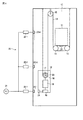
図1は第1の実施形態に係るエレベータの構成を示す図であり、2:1ローピンク形式のエレベータの構成が示されている。
(First embodiment)
FIG. 1 is a diagram showing the configuration of the elevator according to the first embodiment, and shows the configuration of a 2: 1 low pink type elevator.
昇降路10の中に乗りかご11とカウンタウエイト(吊り合い錘)12が設けられており、それぞれに図示せぬガイドレールに昇降動作可能に支持されている。乗りかご11は、かご下にシーブ14を有しており、そのシーブ14の下側に一端が昇降路頂上部に固定されたロープ13が架設されている。
A
このロープ13は、昇降路頂上部に設けられたシーブ15を介してカウンタウエイト12に設けられたトラクションシーブ16に巻回され、その他端部を昇降路頂上部に固定している。これにより、乗りかご11とカウンタウエイト12を2:1ローピンク形式で支持している。
The
また、カウンタウエイト12には、モータ17、制御装置18、バッテリ19が搭載されている。モータ17は、乗りかご11とカウンタウエイト12を昇降動作させるための駆動装置である。このモータ17の回転軸に取り付けられたトラクションシーブ16が回転することで、トラクションシーブ16に巻回されたロープ13を介して乗りかご11とカウンタウエイト12がつるべ式に昇降動作する。
Further, the counterweight 12 is equipped with a
制御装置18は、モータ17の駆動制御を含むエレベータ全体の制御を行う。なお、この制御装置18の機能構成については、後に図2を参照して説明する。バッテリ19は、エレベータの駆動に必要な電力を蓄える。
The
また、本実施形態において、昇降路10にはカウンタウエイト12に非接触で所要の電力を供給するための給電システム20が設けられている。
In the present embodiment, the
この給電システム20は、三相交流電源21に接続された複数の電源装置22−1,22−2,…22−nと、これらの電源装置22−1,22−2,…22−nに接続された非接触給電装置23−1,23−2,…23−nとからなる。
This
電源装置22−1,22−2,…22−nは、建物の各階に対応して設けられており、それぞれに三相交流電源21から供給される電力をエレベータの駆動に必要な電力に変換する。
The power supply devices 22-1 2-2,... 22-n are provided corresponding to the respective floors of the building, and each converts power supplied from the three-phase
非接触給電装置23−1,23−2,…23−nは、乗りかご11が各階で停止しているときのカウンタウエイト12の位置に合わせて昇降路10内に配設されている。これらの非接触給電装置23−1,23−2,…23−nは、カウンタウエイト12に設けられた受電装置24と対向したときに非接触で給電を行う。
The contactless power feeding devices 23-1, 23-2, ... 23-n are arranged in the
なお、非接触給電の方式としては、例えば電磁誘導方式が用いられる。「電磁誘導方式」は、2つの隣接するコイルの一方(給電側コイル)に電流を流したときに発生する磁束を媒介として他方のコイル(受電側コイル)に送電する方式である。この他に、電流を電磁波に変換し、アンテナを介して送電する「電波方式」や、電磁界の共鳴現象を利用した「電磁界共鳴方式」などがあるが、本発明ではこれらの方式に特に限定されるものではない。 For example, an electromagnetic induction method is used as a non-contact power supply method. The “electromagnetic induction method” is a method of transmitting power to the other coil (power receiving side coil) through the magnetic flux generated when a current is passed through one of the two adjacent coils (power feeding side coil). In addition to this, there are a "radio wave system" that converts current into electromagnetic waves and transmits power through an antenna, and an "electromagnetic field resonance system" that uses the resonance phenomenon of electromagnetic fields. It is not limited.
また、図1の例では、各階に非接触給電装置23−1,23−2,…23−nが設置されているが、その個数は任意であり、例えば最上階と最下階にだけ設置しておくことでも良い。 In addition, in the example of FIG. 1, the non-contact power feeding devices 23-1, 23-2, ... 23-n are installed on each floor, but the number is arbitrary, for example, installed only on the top floor and the bottom floor. It is also possible to keep it.
また、モータ17の回転軸にパルスジェネレータ25が設けられている。パルスジェネレータ25は、モータ17の回転を検出し、1回転に数百回のパルス信号を出力する。制御装置18は、このパルス信号をカウントすることで、現在の乗りかご11の位置を把握する。
A
一方、乗りかご11の底部には、積載荷重を検出するための荷重センサ26が設けられている。この荷重センサ26によって検出された積載荷重を示す信号は、図示せぬ伝送ケーブルを介して制御装置18に与えられる。
On the other hand, a load sensor 26 for detecting a loaded load is provided at the bottom of the
このような構成において、カウンタウエイト12に搭載されたバッテリ19から電力を得ることで、モータ17を駆動して乗りかご11とカウンタウエイト12を運転動作させる。また、乗りかご11が各階で停止したときに、非接触給電装置23−1,23−2,…23−nの中でカウンタウエイト12に設けられた受電装置24と対向した非接触給電装置を通じて電力を受け、その電力をバッテリ19に蓄える。
In such a configuration, by obtaining power from the
ここで、非接触給電装置23−1,23−2,…23−nは、カウンタウエイト12側の受電装置24と精度良く向かい合っていないと給電できない。また、非接触給電装置23−1,23−2,…23−nや受電装置24に何らかの異常が発生すると、著しく給電効率が低下してバッテリ不足となり、エレベータを正常に運転できなくなる。
Here, the non-contact power feeding devices 23-1, 23-2,... 23-n cannot feed power unless they face the power receiving
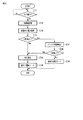
図2は第1の実施形態におけるエレベータの制御装置18の機能構成を示すブロック図である。なお、図2では、各階の乗場に設置された非接触給電装置23−1,23−2,…23−nを代表して任意の階に設置された非接触給電装置に符号23を付して説明する。
FIG. 2 is a block diagram showing a functional configuration of the
図1に示したように、カウンタウエイト12には受電装置24が設置されている。受電装置24は、乗りかご11の着床に伴い、非接触給電装置23と対向したときに非接触給電装置23から所要の電力を非接触で受ける。
As shown in FIG. 1, a
ここで、第1の実施形態において、受電装置24内に非接触給電装置23から得られる電流値(受電量)を検出するための電流センサ31が設けられており、その電流センサ31の検出信号が制御装置18に入力されるようになっている。
Here, in the first embodiment, a
制御装置18には、電力監視部32、外部発報部33、制御パラメータ切替部34、運転制御部35が備えられている。
The
電力監視部32は、電流センサ31によって検出された電流値に基づいて給電時の電力量を監視し、その電力が一定値以下に低下している状態が検出された場合に異常信号を外部発報部33と制御パラメータ切替部34に出力する。
The
外部発報部33は、電力監視部32から電力低下の異常信号を入力すると、外部に対して、その旨を発報する。ここで言う「外部」とは、建物内の図示せぬエレベータ監視室あるいは遠隔地でエレベータの状態を通信ネットワークを介して遠隔監視している図示せぬ監視センタなどである。
When receiving the power drop abnormality signal from the
制御パラメータ切替部34は、電力監視部32から電力低下の異常信号を入力すると、エレベータの運転パラメータを省エネ運転用に切り替える。運転パラメータとは、エレベータの運転に関わるパラメータのことであり、例えば定格速度、加減速度、ジャーク(加減速度の時間変化率)、ドアの開閉速度やかご内照明の照度、かご内のアナウンス装置や空調装置の動作条件などを含む。
When the control
運転制御部35は、モータ17の駆動を制御して、乗りかご11とカウンタウエイト12を昇降動作させる。その際、制御パラメータ切替部34から省エネ運転用の運転パラメータが与えられると、運転制御部35は、その運転パラメータを用いてエレベータの運転モードを省エネ運転モードに切り替えて運転する。
The
なお、36はモータ17の駆動装置として用いられるインバータ装置である。このインバータ装置36は、図1では図示を省略しているが、実際にはモータ17と共にカウンタウエイト12に設けられている。
次に、第1の実施形態の動作を説明する。
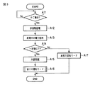
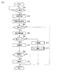
図3は第1の実施形態におけるエレベータの運転動作を示すフローチャートである。
Next, the operation of the first embodiment will be described.
FIG. 3 is a flowchart showing the operation of the elevator according to the first embodiment.
乗りかご11が走行中にあるときは、カウンタウエイト12に搭載されたバッテリ19から電力を得て、モータ17が回転駆動している。
When the
乗りかご11が任意の階に着床すると(ステップA11のYes)、カウンタウエイト12に設置された受電装置24と非接触給電装置23と対向して、非接触給電装置23から非接触で電力を受け、その電力をバッテリ19に蓄える(ステップA12)。
When the
ここで、受電装置24に設けられた電流センサ31によって給電時の電流値が検出される。制御装置18では、電流センサ31によって検出される電流値を監視する(ステップA13)。その電流値が一定値以下(例えば給電正常時の半分以下)であった場合に(ステップA14のYes)、制御装置18は、何らかの原因で給電時の電力が低下した状態にあるものと判断し、その旨を外部(エレベータ管理室あるいは監視センタ)に発報する(ステップA15)。
Here, a current value during power feeding is detected by a
また、制御装置18は、エレベータの運転パラメータを省エネ用に切り替え、省エネ運転モードでエレベータを運転する(ステップA16)。具体的には、例えばエレベータ(乗りかご)の定格速度、加減速度、ジャークを通常時の20%減に落したり、かごドアの戸開閉速度を通常時の20%減に落すなどして、走行中に消費される電力を極力抑えて運転する。なお、この省エネ運転中に乗りかご11内の照明機器の輝度や空調の動作頻度を通常時より下げるようにしても良い。
Further, the
一方、電流センサ31によって検出される電流値が一定値より多く、給電に問題ないと判断された場合には(ステップA14のNo)、制御装置18は、通常の運転モードを継続する(ステップA17)。
On the other hand, when the current value detected by the
このように、何らかの原因で給電時の電力が低下した状態が検出された場合に外部に発報して、その間、省エネ運転モードに切り替えることで、保守員が現場に到着するまでの間、消費電力を抑えながら運転を継続することができる。 In this way, when it is detected that the power supply during power supply has been reduced for some reason, it is reported to the outside, and during that time, switching to the energy-saving operation mode allows consumption until maintenance personnel arrive at the site. Operation can be continued while suppressing power.
なお、給電時の電力低下により省エネ運転モードに切り替えた場合に、常に省エネ運転を行うのではなく、力行運転時にのみ省エネ運転を行うようにしても良い。 In addition, when switching to the energy saving operation mode due to power reduction during power feeding, the energy saving operation may be performed only during the power running operation instead of always performing the energy saving operation.
すなわち、例えば乗りかご11が昇降路10の下方向に動く場合に、そのときの乗りかご11の荷重がカウンタウエイト12より重ければ、バランス方向に動くため、モータ17が発電機として機能することになり、電力が生じる。同様に、乗りかご11が上方向に動く場合に、そのときの乗りかご11の荷重がカウンタウエイト12より軽ければ、バランス方向に動くため、モータ17が発電機として機能して電力が生じる。
That is, for example, when the
このように、バランス方向に動くことにより動力を必要とせずに乗りかご11を運転することを「回生運転」と呼び、そのときに発生する電力を「回生電力」と呼ぶ。また、その逆に、モータ17の動力を必要する運転のことを「力行運転」と呼ぶ。なお、現在の運転状態が回生運転であるのか力行運転であるのかは、乗りかご11の運転方向と積載荷重から判断できる。
Thus, operating the
図4は第1の実施形態における省エネ運転モード時のエレベータの運転動作を示すフローチャートである。 FIG. 4 is a flowchart showing the operation operation of the elevator in the energy saving operation mode in the first embodiment.
制御装置18は、エレベータの運転情報として乗りかご11の運転方向と積載荷重を取得する(ステップB11)。運転方向は現在位置と呼びの方向から判断でき、積載荷重は乗りかご11の底部に設置された荷重センサ26によって検出される。
The
制御装置18は、乗りかご11の運転方向と積載荷重に基づいて呼びに対する運転が力行運転であるか回生運転であるかを判断する(ステップB12)。その結果、力行運転であった場合に(ステップB12のYes)、制御装置18は省エネ運転を実行し、定格速度を下げるなどして乗りかご11を呼びのあった階に応答させる(ステップB13)。
The
一方、回生運転であれば(ステップB12のNo)、制御装置18は省エネ運転にせずに、そのまま通常運転により乗りかご11を呼びのあった階に応答させる(ステップB14)。
On the other hand, if the operation is a regenerative operation (No in Step B12), the
このように、電力を必要とする力行運転時にのみ省エネ運転を行うことで、できるだけ運転効率を下げないようにして運転を継続することが可能となる。 As described above, by performing the energy saving operation only during the power running operation that requires electric power, it is possible to continue the operation without reducing the operation efficiency as much as possible.
(第2の実施形態)
次に、第2の実施形態を説明する。
(Second Embodiment)
Next, a second embodiment will be described.
第2の実施形態では、上記第1の実施形態の構成に加え、バッテリ残量が一定値以下に低下した場合に省エネ運転モードに切り替えるようにしたものである。 In the second embodiment, in addition to the configuration of the first embodiment, when the remaining battery level falls below a certain value, the mode is switched to the energy saving operation mode.
図5は第2の実施形態におけるエレベータの制御装置18の機能構成を示すブロック図である。なお、上記第1の実施形態における図2の構成と同一部分には同一符号を付して、その説明は省略するものとする。
FIG. 5 is a block diagram showing a functional configuration of the
図2との違いは、制御装置18にバッテリ残量検出部37が追加されている点である。バッテリ残量検出部37は、バッテリ19の電圧から現在の残量(電力量)を検出する機能を備え、バッテリ19の残量が一定以下に低下した場合に異常信号を外部発報部33と制御パラメータ切替部34に出力する。
The difference from FIG. 2 is that a remaining battery
図6は第2の実施形態におけるエレベータの運転動作を示すフローチャートである。 FIG. 6 is a flowchart showing the operation of the elevator in the second embodiment.
乗りかご11が走行中にあるときは、カウンタウエイト12に搭載されたバッテリ19から電力を得て、モータ17が回転駆動している。
When the
乗りかご11が任意の階に着床すると(ステップC11のYes)、カウンタウエイト12に設置された受電装置24と非接触給電装置23と対向して、非接触給電装置23から非接触で電力を受け、その電力をバッテリ19に蓄える(ステップC12)。
When the
ここで、受電装置24に設けられた電流センサ31によって給電時の電流値が検出される。制御装置18では、電流センサ31によって検出される電流値を監視する(ステップC13)。その電流値が一定値以下(例えば給電正常時の半分以下)であった場合に(ステップC14のYes)、制御装置18は、何らかの原因で給電時の電力が低下した状態にあるものと判断し、その旨を外部(エレベータ管理室あるいは監視センタ)に発報する(ステップC15)。
Here, a current value during power feeding is detected by a
また、制御装置18は、エレベータの運転パラメータを省エネ用に切り替え、省エネ運転モードでエレベータを運転する(ステップC16)。具体的には、例えばエレベータ(乗りかご)の定格速度、加減速度、ジャークを通常時の20%減に落したり、かごドアの戸開閉速度を通常時の20%減に落すなどして、走行中に消費される電力を極力抑えて運転する。なお、この省エネ運転中に乗りかご11内の照明機器の輝度や空調の動作頻度を通常時より下げるようにしても良い。
Further, the
一方、電流センサ31によって検出される電流値が一定値より多いと判断された場合に(ステップC14のNo)、制御装置18は、バッテリ19の電圧から現在の残量を検出する(ステップC17)。その結果、バッテリ19の残量が一定値以下(例えば、バッテリ容量の半分以下)であった場合には(ステップC18のYes)、制御装置18は、電力不足により運転に支障が生じるものと判断し、その旨を外部に発報すると共に(ステップC15)、エレベータの運転パラメータを省エネ用に切り替え、省エネ運転モードでエレベータを運転する(ステップC16)。
On the other hand, when it is determined that the current value detected by the
このように、給電中の電力に加え、バッテリ残量も監視することで、より確実に現在のエレベータの電力状態を把握でき、電力不足により運転に支障が生じる場合に適切に対応することができる。 In this way, by monitoring the remaining battery level in addition to the power being fed, the current power state of the elevator can be grasped more reliably, and it is possible to respond appropriately when troubles occur due to power shortage. .
なお、ここでは給電中の電力とバッテリ残量の両方を監視する構成としたが、バッテリ残量だけ監視して、一定値以下に低下した場合に外部発報と共に省エネ運転モードに切り替えるようにしても良い。 In addition, although it was set as the structure which monitors both the electric power and the battery remaining charge during feeding here, when only the battery remaining amount is monitored, when it falls below a fixed value, it will switch to energy saving operation mode with an external alarm. Also good.
さらに、省エネ運転モードでは、図4で説明したように力行運転時にのみ省エネ運転を実行することでも良い。 Further, in the energy saving operation mode, as described with reference to FIG. 4, the energy saving operation may be executed only during the power running operation.
(第3の実施形態)
次に、第3の実施形態について説明する。
(Third embodiment)
Next, a third embodiment will be described.
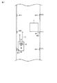
図7は第3の実施形態におけるエレベータの乗りかごの着床時の状態を示す図である。乗りかご11の底部には、乗りかご11の着床レベルを検出するための着床検出センサ41が設けられている。この着床検出センサ41は、昇降路12内の各階の乗り場口の下側に設けられた着検板42−1,42−2…42−nのいずれかに接近することで、乗りかご11が乗り場に着床したことを検出する。
FIG. 7 is a diagram showing a state of the elevator car when landing in the third embodiment. A
このとき、通常は、カウンタウエイト12に設けられた受電装置24は、非接触給電装置23−1,23−2,…23−nのいずれに対向して給電可能な状態にある。ところが、ロープ13の伸びやトラクションシーブ16の摩耗等により非接触給電装置23−1,23−2,…23−nと受電装置24との間に位置ずれが生じている場合がある。このような位置ずれが生じていると、給電効率が低下するため、エレベータ側では電力不足(バッテリ不足)となり、運転に支障が出る。
At this time, normally, the
第3の実施形態では、非接触給電装置23−1,23−2,…23−nと受電装置24との位置ずれによる電力低下を防ぐようにしたものである。
In the third embodiment, the power reduction due to the positional deviation between the non-contact power feeding devices 23-1, 23-2,... 23-n and the
図8は第3の実施形態におけるエレベータの制御装置18の機能構成を示すブロック図である。なお、上記第1の実施形態における図2の構成と同一部分には同一符号を付して、その説明は省略するものとする。
FIG. 8 is a block diagram illustrating a functional configuration of the
図2との違いは、制御装置18に位置調整部38が追加されている点である。位置調整部38は、乗りかご11の着床時に電力監視部32によって電力低下が検出された場合に着床位置の微調整を行う。この調整動作で電力が上がった場合に、運転制御部35はその調整後の位置を記憶しておき、次回の運転から乗りかご11を上記微調整後の位置に着床させるように位置制御を行う。
The difference from FIG. 2 is that a
図9は第3の実施形態におけるエレベータの運転動作を示すフローチャートである。 FIG. 9 is a flowchart showing the operation of the elevator according to the third embodiment.
乗りかご11が走行中にあるときは、カウンタウエイト12に搭載されたバッテリ19から電力を得て、モータ17が回転駆動している。
When the
乗りかご11が任意の階に着床すると(ステップD11のYes)、カウンタウエイト12に設置された受電装置24と非接触給電装置23と対向して、非接触給電装置23から非接触で電力を受け、その電力をバッテリ19に蓄える(ステップD12)。
When the
ここで、受電装置24に設けられた電流センサ31によって給電時の電流値が検出される。制御装置18では、電流センサ31によって検出される電流値を監視する(ステップD13)。その電流値が一定値以下(例えば給電正常時の半分以下)であった場合に(ステップD14のYes)、制御装置18は、非接触給電装置23と受電装置24との位置ずれの可能性を考え、着床位置の微調整を行う(ステップD15)。
Here, a current value during power feeding is detected by a
具体的には、モータ17を駆動して、乗りかご11を上方向あるいは下方向に着床レベルに影響でない程度に少しだけ動かす。なお、この微調整の動作は、一定時間以上呼びがない状態で行うことが好ましい。
Specifically, the
この微調整により電力がアップした場合、つまり、電流センサ31によって検出される電流値が一定値よりも上がった場合に(ステップD16のYes)、制御装置18は、非接触給電装置23と受電装置24との位置ずれが原因であったと判断し、その調整後の位置(パルスジェネレータ25のパルス数)を記憶しておき、次回の運転から乗りかご11を上記微調整後の位置に着床させるように位置制御を行う(ステップD17)。
When the power is increased by this fine adjustment, that is, when the current value detected by the
さらに着床位置の調整量が一定以上となった場合は(ステップD20Yes)、着床時のかごと乗り場に生じる段差の大きさが許容範囲外であるとし外部発報をし、非接触給電装置23あるいは受電装置24の取り付け位置に調整が必要なことを連絡する(ステップD21)。
Further, when the amount of adjustment of the landing position becomes equal to or greater than a certain level (Step D20 Yes), an external notification is given that the size of the step generated at the landing and the platform is outside the allowable range, and the non-contact
一方、微調整により電力がアップしない場合、つまり、電流センサ31によって検出される電流値が一定値以下であれば(ステップD16のNo)、制御装置18は、電力不足により運転に支障が生じるものと判断し、その旨を外部に発報すると共に(ステップD18)、エレベータの運転パラメータを省エネ用に切り替え、省エネ運転モードでエレベータを運転する(ステップD19)。
On the other hand, if the power does not increase due to the fine adjustment, that is, if the current value detected by the
このように、着床位置を微調整する機能を備えることで、非接触給電装置23と受電装置24との位置ずれによる電力低下を防ぐことができる。
As described above, by providing the function of finely adjusting the landing position, it is possible to prevent power reduction due to the positional deviation between the non-contact
なお、ここでは給電中の電力を監視する構成としたが、上記第2の実施形態のように給電中の電力とバッテリ残量の両方を監視する構成としても良い。 In addition, although it was set as the structure which monitors the electric power in electric power feeding here, it is good also as a structure which monitors both the electric power in electric power feeding and a battery remaining charge like the said 2nd Embodiment.
さらに、省エネ運転モードでは、図4で説明したように力行運転時にのみ省エネ運転を実行することでも良い。 Further, in the energy saving operation mode, as described with reference to FIG. 4, the energy saving operation may be executed only during the power running operation.
以上述べた少なくとも1つの実施形態によれば、非接触給電装置からの給電が不足した状態に対処して運転を継続することのできるエレベータを提供することができる。 According to at least one embodiment described above, it is possible to provide an elevator capable of coping with a state where power supply from the non-contact power supply device is insufficient and continuing operation.
なお、本発明のいくつかの実施形態を説明したが、これらの実施形態は、例として提示したものであり、発明の範囲を限定することは意図していない。これら新規な実施形態は、その他の様々な形態で実施されることが可能であり、発明の要旨を逸脱しない範囲で、種々の省略、置き換え、変更を行うことができる。これら実施形態やその変形は、発明の範囲や要旨に含まれるとともに、特許請求の範囲に記載された発明とその均等の範囲に含まれる。 In addition, although some embodiment of this invention was described, these embodiment is shown as an example and is not intending limiting the range of invention. These novel embodiments can be implemented in various other forms, and various omissions, replacements, and changes can be made without departing from the scope of the invention. These embodiments and modifications thereof are included in the scope and gist of the invention, and are included in the invention described in the claims and the equivalents thereof.
10…昇降路、11…乗りかご、12…カウンタウエイト、13…ロープ、14…シーブ、15…シーブ、16…トラクションシーブ、17…モータ、18…制御装置、19…バッテリ、20…給電システム、21…三相交流電源、22−1,22−2〜22−n…電源装置、23−1,23−2〜23−n…非接触給電装置、24…受電装置、25…パルスジェネレータ、26…荷重センサ、31…電流センサ、32…電力監視部、33…外部発報部、34…制御パラメータ切替部、35…運転制御部、36…インバータ装置、37…バッテリ残量検出部、38…位置調整部。
DESCRIPTION OF
Claims (6)
上記カウンタウエイトに設けられ、上記乗りかごが各階で着床したときに上記非接触給電装置に対向して上記非接触給電装置から供給される電力を受ける受電装置と、
この受電装置を通じて得られる給電時の電力を監視する電力監視手段と、
この電力監視手段によって電力が一定値以下に低下している状態が検出された場合に、省エネ運転モードに切り替えて運転する運転制御手段と
を具備したことを特徴とするエレベータ。 In an elevator equipped with a non-contact power feeding device that supplies power in a non-contact manner to a counterweight that moves up and down with a car in a hoistway,
A power receiving device that is provided in the counterweight and receives power supplied from the non-contact power feeding device opposite the non-contact power feeding device when the car is landed on each floor;
Power monitoring means for monitoring the power at the time of power supply obtained through the power receiving device;
An elevator comprising: an operation control unit that switches to an energy-saving operation mode when a state in which the power is reduced to a predetermined value or less is detected by the power monitoring unit.
このバッテリの残量を検出するバッテリ残量検出手段とを備え、
上記運転制御手段は、
上記電力監視手段によって電力が一定値以下に低下している状態が検出された場合、あるいは、上記バッテリ残量検出手段によってバッテリ残量が一定値以下に低下している状態が検出された場合に、省エネ運転モードに切り替えて運転することを特徴とする請求項1記載のエレベータ。 A battery for storing electric power supplied from the contactless power supply device;
Battery remaining amount detecting means for detecting the remaining amount of the battery,
The operation control means includes
When the power monitoring means detects that the power is decreasing below a certain value, or when the battery remaining capacity detecting means detects that the remaining battery power is below a certain value The elevator according to claim 1, wherein the elevator is operated by switching to an energy saving operation mode.
上記乗りかごの運転方向と積載荷重に基づいて力行運転であるか否かを判断し、力行運転の場合に上記省エネ運転モードに切り替えて運転することを特徴とする請求項1記載のエレベータ。 The operation control means includes
2. The elevator according to claim 1, wherein it is determined whether or not a power running operation is performed based on a driving direction of the car and a loaded load, and the power saving operation mode is switched to the energy saving operation mode in the case of the power running operation.
上記電力監視手段は、
上記電流センサによって検出された電流値に基づいて給電時の電力を監視することを特徴とする請求項1記載のエレベータ。 A current sensor provided in the power receiving device for detecting a current value obtained from the non-contact power feeding device;
The power monitoring means includes
The elevator according to claim 1, wherein the electric power during power feeding is monitored based on a current value detected by the current sensor.
上記運転制御手段は、
上記位置調整手段による調整動作で電力が上がった場合に、次回の運転から上記乗りかごを上記調整後の位置に着床させるように位置制御を行うことを特徴とする請求項1記載のエレベータ。 A position adjusting means for finely adjusting the landing position of the car when the power monitoring means detects a state in which the power is reduced below a certain value;
The operation control means includes
2. The elevator according to claim 1, wherein position control is performed so that, when power is increased by the adjustment operation by the position adjustment means, the car is landed at the adjusted position from the next operation.
Priority Applications (2)
| Application Number | Priority Date | Filing Date | Title |
|---|---|---|---|
| JP2011037066A JP2012175857A (en) | 2011-02-23 | 2011-02-23 | Elevator |
| CN201110386658.7A CN102649522B (en) | 2011-02-23 | 2011-11-29 | Elevator |
Applications Claiming Priority (1)
| Application Number | Priority Date | Filing Date | Title |
|---|---|---|---|
| JP2011037066A JP2012175857A (en) | 2011-02-23 | 2011-02-23 | Elevator |
Publications (1)
| Publication Number | Publication Date |
|---|---|
| JP2012175857A true JP2012175857A (en) | 2012-09-10 |
Family
ID=46691656
Family Applications (1)
| Application Number | Title | Priority Date | Filing Date |
|---|---|---|---|
| JP2011037066A Pending JP2012175857A (en) | 2011-02-23 | 2011-02-23 | Elevator |
Country Status (2)
| Country | Link |
|---|---|
| JP (1) | JP2012175857A (en) |
| CN (1) | CN102649522B (en) |
Cited By (10)
| Publication number | Priority date | Publication date | Assignee | Title |
|---|---|---|---|---|
| JP2013071796A (en) * | 2011-09-27 | 2013-04-22 | Toshiba Elevator Co Ltd | Noncontact power feeding system for elevator |
| JP2014172705A (en) * | 2013-03-08 | 2014-09-22 | Toshiba Elevator Co Ltd | Elevator control device, and elevator control method |
| CN104555680A (en) * | 2014-12-29 | 2015-04-29 | 昆山京都电梯有限公司 | Lift capable of automatically charging storage batteries |
| JP5882429B1 (en) * | 2014-09-12 | 2016-03-09 | 東芝エレベータ株式会社 | Power supply |
| JP2018162113A (en) * | 2017-03-24 | 2018-10-18 | 東芝エレベータ株式会社 | Non-contact power supply system of elevator |
| WO2019106949A1 (en) * | 2017-11-28 | 2019-06-06 | 株式会社日立製作所 | Elevator and elevator control device |
| JP2019156545A (en) * | 2018-03-09 | 2019-09-19 | 東芝エレベータ株式会社 | Non-contact power supply system for elevator |
| WO2020194826A1 (en) * | 2019-03-28 | 2020-10-01 | 株式会社日立製作所 | Elevator system |
| CN113247717A (en) * | 2020-02-13 | 2021-08-13 | 东芝电梯株式会社 | Elevator control system |
| JP7336084B1 (en) | 2022-07-07 | 2023-08-31 | フジテック株式会社 | Proximity notification device for counterweight in elevator |
Families Citing this family (10)
| Publication number | Priority date | Publication date | Assignee | Title |
|---|---|---|---|---|
| US10135299B2 (en) * | 2015-08-25 | 2018-11-20 | Otis Elevator Company | Elevator wireless power transfer system |
| JP2018020899A (en) * | 2016-08-05 | 2018-02-08 | 株式会社日立製作所 | Elevator system |
| JP2018024496A (en) * | 2016-08-09 | 2018-02-15 | 株式会社日立製作所 | Elevator device |
| CN106655262B (en) * | 2016-11-25 | 2019-01-18 | 上海工程技术大学 | A kind of elevator energy recycling wireless charging system |
| JP6795462B2 (en) * | 2017-06-15 | 2020-12-02 | 株式会社日立製作所 | Elevator device |
| CN107473041A (en) * | 2017-08-08 | 2017-12-15 | 曾美枝 | A kind of emergency staircase |
| WO2019053825A1 (en) * | 2017-09-13 | 2019-03-21 | 三菱電機株式会社 | Control device and control method for elevators |
| US11670961B2 (en) * | 2018-12-14 | 2023-06-06 | Otis Elevator Company | Closed loop control wireless power transmission system for conveyance system |
| US20200195047A1 (en) * | 2018-12-14 | 2020-06-18 | Otis Elevator Company | Car to call point wireless power charging |
| CN110182668A (en) * | 2019-06-10 | 2019-08-30 | 攀枝花攀钢集团设计研究院有限公司 | Outdoor Solar-energy elevator |
Citations (12)
| Publication number | Priority date | Publication date | Assignee | Title |
|---|---|---|---|---|
| JP2001163533A (en) * | 1999-12-09 | 2001-06-19 | Hitachi Ltd | Elevator |
| JP2002037546A (en) * | 2000-07-24 | 2002-02-06 | Hitachi Ltd | Elevator device |
| WO2002057171A1 (en) * | 2001-01-19 | 2002-07-25 | Hitachi, Ltd. | Elevator |
| JP2002338147A (en) * | 2001-05-16 | 2002-11-27 | Mitsubishi Electric Corp | Elevator device and its operating method |
| JP2003209903A (en) * | 2001-11-07 | 2003-07-25 | Tsubakimoto Chain Co | Non-contact power feeder and non-contact power feeding system |
| JP2005029291A (en) * | 2003-07-07 | 2005-02-03 | Hitachi Ltd | Tail-cordless elevator |
| JP2006193275A (en) * | 2005-01-13 | 2006-07-27 | Mitsubishi Electric Corp | Power supply system of elevator car |
| JP2007153574A (en) * | 2005-12-07 | 2007-06-21 | Mitsubishi Electric Corp | Elevator device |
| JP2009286635A (en) * | 2007-04-13 | 2009-12-10 | Hitachi Ltd | Electric power control device of elevator car |
| JP2010148210A (en) * | 2008-12-17 | 2010-07-01 | Nippon Soken Inc | Contactless power supply circuit and induction type power supply circuit |
| JP2010149989A (en) * | 2008-12-25 | 2010-07-08 | Mitsubishi Electric Building Techno Service Co Ltd | Elevator |
| JP2011026034A (en) * | 2009-07-22 | 2011-02-10 | Mitsubishi Electric Corp | Group supervisory operation control method of elevator |
Family Cites Families (3)
| Publication number | Priority date | Publication date | Assignee | Title |
|---|---|---|---|---|
| JP2002211855A (en) * | 2001-01-12 | 2002-07-31 | Mitsubishi Electric Corp | Control system for elevator |
| JP4927277B2 (en) * | 2001-09-28 | 2012-05-09 | 東芝エレベータ株式会社 | elevator |
| JP4727166B2 (en) * | 2004-05-13 | 2011-07-20 | 三菱電機株式会社 | Elevator control device |
-
2011
- 2011-02-23 JP JP2011037066A patent/JP2012175857A/en active Pending
- 2011-11-29 CN CN201110386658.7A patent/CN102649522B/en active Active
Patent Citations (12)
| Publication number | Priority date | Publication date | Assignee | Title |
|---|---|---|---|---|
| JP2001163533A (en) * | 1999-12-09 | 2001-06-19 | Hitachi Ltd | Elevator |
| JP2002037546A (en) * | 2000-07-24 | 2002-02-06 | Hitachi Ltd | Elevator device |
| WO2002057171A1 (en) * | 2001-01-19 | 2002-07-25 | Hitachi, Ltd. | Elevator |
| JP2002338147A (en) * | 2001-05-16 | 2002-11-27 | Mitsubishi Electric Corp | Elevator device and its operating method |
| JP2003209903A (en) * | 2001-11-07 | 2003-07-25 | Tsubakimoto Chain Co | Non-contact power feeder and non-contact power feeding system |
| JP2005029291A (en) * | 2003-07-07 | 2005-02-03 | Hitachi Ltd | Tail-cordless elevator |
| JP2006193275A (en) * | 2005-01-13 | 2006-07-27 | Mitsubishi Electric Corp | Power supply system of elevator car |
| JP2007153574A (en) * | 2005-12-07 | 2007-06-21 | Mitsubishi Electric Corp | Elevator device |
| JP2009286635A (en) * | 2007-04-13 | 2009-12-10 | Hitachi Ltd | Electric power control device of elevator car |
| JP2010148210A (en) * | 2008-12-17 | 2010-07-01 | Nippon Soken Inc | Contactless power supply circuit and induction type power supply circuit |
| JP2010149989A (en) * | 2008-12-25 | 2010-07-08 | Mitsubishi Electric Building Techno Service Co Ltd | Elevator |
| JP2011026034A (en) * | 2009-07-22 | 2011-02-10 | Mitsubishi Electric Corp | Group supervisory operation control method of elevator |
Cited By (16)
| Publication number | Priority date | Publication date | Assignee | Title |
|---|---|---|---|---|
| JP2013071796A (en) * | 2011-09-27 | 2013-04-22 | Toshiba Elevator Co Ltd | Noncontact power feeding system for elevator |
| JP2014172705A (en) * | 2013-03-08 | 2014-09-22 | Toshiba Elevator Co Ltd | Elevator control device, and elevator control method |
| JP5882429B1 (en) * | 2014-09-12 | 2016-03-09 | 東芝エレベータ株式会社 | Power supply |
| CN104555680A (en) * | 2014-12-29 | 2015-04-29 | 昆山京都电梯有限公司 | Lift capable of automatically charging storage batteries |
| JP2018162113A (en) * | 2017-03-24 | 2018-10-18 | 東芝エレベータ株式会社 | Non-contact power supply system of elevator |
| JPWO2019106949A1 (en) * | 2017-11-28 | 2020-10-22 | 株式会社日立製作所 | Elevator and elevator control device |
| WO2019106949A1 (en) * | 2017-11-28 | 2019-06-06 | 株式会社日立製作所 | Elevator and elevator control device |
| CN111212801A (en) * | 2017-11-28 | 2020-05-29 | 株式会社日立制作所 | Elevator and elevator control device |
| JP2019156545A (en) * | 2018-03-09 | 2019-09-19 | 東芝エレベータ株式会社 | Non-contact power supply system for elevator |
| WO2020194826A1 (en) * | 2019-03-28 | 2020-10-01 | 株式会社日立製作所 | Elevator system |
| JPWO2020194826A1 (en) * | 2019-03-28 | 2021-12-23 | 株式会社日立製作所 | Elevator system |
| JP7138773B2 (en) | 2019-03-28 | 2022-09-16 | 株式会社日立製作所 | elevator system |
| CN113247717A (en) * | 2020-02-13 | 2021-08-13 | 东芝电梯株式会社 | Elevator control system |
| JP2021127210A (en) * | 2020-02-13 | 2021-09-02 | 東芝エレベータ株式会社 | Elevator control system |
| CN113247717B (en) * | 2020-02-13 | 2023-03-31 | 东芝电梯株式会社 | Elevator control system |
| JP7336084B1 (en) | 2022-07-07 | 2023-08-31 | フジテック株式会社 | Proximity notification device for counterweight in elevator |
Also Published As
| Publication number | Publication date |
|---|---|
| CN102649522B (en) | 2015-06-17 |
| CN102649522A (en) | 2012-08-29 |
Similar Documents
| Publication | Publication Date | Title |
|---|---|---|
| JP2012175857A (en) | Elevator | |
| EP2318300B1 (en) | Method for operating an elevator in an emergency mode | |
| CN101715426B (en) | Fail-safe power control apparatus | |
| US7637353B2 (en) | Control device for elevator | |
| JP5733917B2 (en) | Elevator power supply system | |
| JP4632795B2 (en) | Electric power supply device for elevator car | |
| JP5800650B2 (en) | Elevator contactless power supply system | |
| JP5473883B2 (en) | Elevator equipment | |
| EP2576406B1 (en) | Method for limiting the loading of an elevator assembly, and an elevator assembly | |
| JP6687173B1 (en) | Elevator wireless power supply system and elevator system | |
| EP2800718B1 (en) | Battery mounting in elevator hoistway | |
| EP3447016B1 (en) | Power system for vertical transportation, method and vertical transportation arrangements | |
| JP2019156545A (en) | Non-contact power supply system for elevator | |
| JP2013014424A (en) | Elevator | |
| JP2012246119A (en) | Contactless power feeding system of elevator | |
| JP5800638B2 (en) | Elevator contactless power supply system | |
| JP2013047137A (en) | Contactless power feeding system for elevator | |
| JP2013060262A (en) | Elevator | |
| JP2012184049A (en) | Elevator | |
| JP2013049511A (en) | Non-contacting feed system of elevator | |
| CN102485627A (en) | Carrying device and carrying system | |
| JP5764838B2 (en) | Elevator door system | |
| EP3666704B1 (en) | Car to car wireless power transfer | |
| EP3715303B1 (en) | Multi-shaft power charging | |
| CN111327125B (en) | Closed loop control wireless power transfer system for a conveyor system |
Legal Events
| Date | Code | Title | Description |
|---|---|---|---|
| A621 | Written request for application examination |
Free format text: JAPANESE INTERMEDIATE CODE: A621 Effective date: 20130709 |
|
| RD02 | Notification of acceptance of power of attorney |
Free format text: JAPANESE INTERMEDIATE CODE: A7422 Effective date: 20130709 |
|
| A521 | Written amendment |
Free format text: JAPANESE INTERMEDIATE CODE: A523 Effective date: 20130827 |
|
| A131 | Notification of reasons for refusal |
Free format text: JAPANESE INTERMEDIATE CODE: A131 Effective date: 20140218 |
|
| A02 | Decision of refusal |
Free format text: JAPANESE INTERMEDIATE CODE: A02 Effective date: 20140617 |