EP2800718B1 - Battery mounting in elevator hoistway - Google Patents
Battery mounting in elevator hoistway Download PDFInfo
- Publication number
- EP2800718B1 EP2800718B1 EP12864591.8A EP12864591A EP2800718B1 EP 2800718 B1 EP2800718 B1 EP 2800718B1 EP 12864591 A EP12864591 A EP 12864591A EP 2800718 B1 EP2800718 B1 EP 2800718B1
- Authority
- EP
- European Patent Office
- Prior art keywords
- hoistway
- machine
- bedplate
- power source
- elevator
- Prior art date
- Legal status (The legal status is an assumption and is not a legal conclusion. Google has not performed a legal analysis and makes no representation as to the accuracy of the status listed.)
- Active
Links
- 238000000034 method Methods 0.000 claims description 6
- 230000005540 biological transmission Effects 0.000 description 4
- 230000001419 dependent effect Effects 0.000 description 3
- 230000008901 benefit Effects 0.000 description 2
- 239000004020 conductor Substances 0.000 description 2
- 238000007599 discharging Methods 0.000 description 2
- 238000009434 installation Methods 0.000 description 1
- 238000012423 maintenance Methods 0.000 description 1
- 239000000463 material Substances 0.000 description 1
- 238000012986 modification Methods 0.000 description 1
- 230000004048 modification Effects 0.000 description 1
- 238000004804 winding Methods 0.000 description 1
Images


Classifications
-
- B—PERFORMING OPERATIONS; TRANSPORTING
- B66—HOISTING; LIFTING; HAULING
- B66B—ELEVATORS; ESCALATORS OR MOVING WALKWAYS
- B66B11/00—Main component parts of lifts in, or associated with, buildings or other structures
- B66B11/0035—Arrangement of driving gear, e.g. location or support
- B66B11/0045—Arrangement of driving gear, e.g. location or support in the hoistway
-
- B—PERFORMING OPERATIONS; TRANSPORTING
- B66—HOISTING; LIFTING; HAULING
- B66B—ELEVATORS; ESCALATORS OR MOVING WALKWAYS
- B66B7/00—Other common features of elevators
-
- B—PERFORMING OPERATIONS; TRANSPORTING
- B66—HOISTING; LIFTING; HAULING
- B66B—ELEVATORS; ESCALATORS OR MOVING WALKWAYS
- B66B11/00—Main component parts of lifts in, or associated with, buildings or other structures
- B66B11/001—Arrangement of controller, e.g. location
- B66B11/002—Arrangement of controller, e.g. location in the hoistway
-
- B—PERFORMING OPERATIONS; TRANSPORTING
- B66—HOISTING; LIFTING; HAULING
- B66B—ELEVATORS; ESCALATORS OR MOVING WALKWAYS
- B66B11/00—Main component parts of lifts in, or associated with, buildings or other structures
- B66B11/04—Driving gear ; Details thereof, e.g. seals
- B66B11/08—Driving gear ; Details thereof, e.g. seals with hoisting rope or cable operated by frictional engagement with a winding drum or sheave
Definitions
- Particular embodiments may include any of the features of dependent claims 2 to 6.
- the battery 46 and inverter 48 need not be mounted directly to the bedplate but rather could be mounted elsewhere within the hoistway 22 while still providing significant advantages over current elevator systems in which the battery 46 and inverter 48 are mounted outside of the hoistway.
- the battery 46 and/or inverter 48 could be mounted in the pit 26, on the counterweight 34, on the car 32, on a door lintel 54 provided at each floor at which the elevator stops, on a hoistway wall 56, on a ceiling 58 of the hoistway 22, or anywhere else within the hoistway 22.
Description
- The present disclosure generally relates to elevators, and more particularly relates to battery powered elevators.
- Elevators are well-known devices for navigating people and cargo up and down within multi-story buildings. Traditionally, people and cargo are carried in elevator cars which navigate through hoistways provided vertically within the buildings. Each car is mounted on a plurality of rails to allow for linear translation of the car through the hoistway and is powered by a machine such as an electric motor connected to the car by way of belts, cables, or the like. A counterweight is also typically mounted on adjacent rails to facilitate the smooth movement of the car through the hoistway. The machine, as well as the other mechanical components of the elevator such as a sheave, governor or the like, is typically mounted on a bedplate provided at the top of the hoistway.
- With relatively large elevators, the power and power electronics for energizing the machine are typically provided within a machine room provided at the top of the building. Alternatively, such equipment can be provided within a landing cabinet provided somewhere in the building other than the hoistway. This facilitates maintenance of the system, as well as connection of the building power grid and/or utility power grid to the machine, or if in a relatively large installation, machines for multiple elevators.
US 2002/112924 A1 discloses an elevator having a car and a counterweight which are suspended by a rope with its end fixed at the top of a hoistway. Further, a driving apparatus comprising a winding engine and an electric motor are provided which are mounted in the counter weight. A power feeding apparatus for moving the counter weight is provided which is supported by a power feeding apparatus supporting member extended from a counter weight guide rail.
EP 1 106 559 A2 discloses a power feeding system for an elevator, wherein a rotary motor for driving a counter weight of the elevator car is installed in the counter weight, whereas a feed system for supplying the electric power to the control panel of the counter weight is installed in the hoistway.
WO 03/072478 A1 - In more recent applications, the power used to energize the machine is not fixed or tied to an existing utility grid, but rather is provided by way of self-contained power sources, such as batteries. Among other things, such batteries lower power draw from the building power grid and often times are more reliable than utilities or generators in that they are not dependent on the utility power grid being up and running at all times.
- While effective, as elevator systems have typically employed the aforementioned machine rooms or landing cabinets outside of the hoistways, with existing battery-powered elevator systems, the batteries are therefore currently housed outside the hoistway as well. Typically, the inverter and other power electronics used for the system are also mounted outside of the hoistway.
- It has been discovered that known elevator systems possess inherent inefficiencies resulting from the physical configuration of the systems' components. Furthermore, it has been discovered that these inefficiencies may be mitigated or eliminated by utilizing any of the alternate configurations disclosed herein. By minimizing the physical length of the large gauge lines over which low voltage - high current electrical power signals are transmitted, it is possible to eliminate the significant efficiency losses, elevator performance issues, and the battery life issues inherent in the known elevator systems.
- In accordance with one aspect of the invention, an elevator system is disclosed according to claim 1.
- Particular embodiments may include any of the features of dependent claims 2 to 6.
- Although the exemplary embodiments are described as containing batteries, a person skilled in the art at the time of the invention having the benefit of this disclosure would have understood that the disclosed batteries may be replaced with other power sources without departing from the scope should be deleted of the invention. The battery supplies all the power needed by the machine to move the passenger car under normal operating conditions of the elevator system.
- In accordance with another aspect of the invention, a method is disclosed according to claim 7.
- Particular embodiments may include any of the features of dependent claims 8 and 9.
- While the exemplary embodiments are described as separate embodiments, a person skilled in the art at the time of the invention would have understood that many of the disclosed features are suitable for use in any of the embodiments. For example, any of the embodiments may additionally comprise: a battery as the power source; a motor as the machine; a bed plate to which the power source, the machine, or other electronics (such as an inverter) may be mounted; a counterweight to which the power source may be mounted; and/or a plurality of lintels to which the power source may be mounted.
- Similarly, a method according to any of the disclosed embodiments may also comprise similar features.
- These and other aspects of the disclosure will become more readily apparent upon reading the following detailed description when taken in conjunction with the accompanying drawings.
-
-
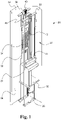
FIG. 1 is a perspective view of an elevator system constructed in accordance with the teachings of the disclosure; -
FIG. 2 is a side view of an elevator system not covered by the claims; and -
FIG. 3 is a schematic representation of alternative embodiments of elevator systems constructed in accordance with the teachings of the disclosure. - While the following disclosure will be made with reference to certain exemplary embodiments, it should be understood that various changes may be made and equivalents may be substituted for elements thereof without departing from the scope of the invention. In addition, many modifications may be made to adapt a particular situation or material to the teachings of the disclosure without departing from its scope. It is intended that the disclosure not be limited to the particular embodiments disclosed as the best mode contemplated for carrying out this disclosure, but that the scope of the invention should include all embodiments falling with the scope of the appended claims
- Referring now to the drawings, and with specific reference to
FIG. 1 , an elevator system constructed in accordance with the teachings of the disclosure is generally referred to byreference numeral 20. As shown therein, theelevator system 20 may include ahoistway 22 defining a vertically-disposed, open channel through a multistory building (not shown) employing theelevator system 20. Theelevator system 20 may further include a plurality ofrails 24 extending from a bottom orpit 26 of thehoistway 22 to atop 28 of thehoistway 22 where therails 24 terminate in a connection to abedplate 30. Therails 24 provide structure to facilitate linear movement of anelevator car 32 through thehoistway 22. Moreover,rails 33 provide a similar mechanism by which acounterweight 34 can also move linearly through thehoistway 22. - In order to drive the
car 32 through thehoistway 22, amachine 36 is employed. Themachine 36 may be provided in the form of an electric motor or any other form of prime mover. As shown in conjunction withFIG. 2 as well, themachine 36 may include anoutput shaft 38 on which one ormore sheaves 40 are mounted. Belts, cables, or other loopedpower transmission devices 42 are then trained around thesheave 40 for connection to thepassenger car 32 at afirst end 44, and to thecounterweight 34 at asecond end 45. - Referring now to
FIG. 2 , which is not covered by the claims thebedplate 30 can also be used to mount the power source and power electronics for themachine 36. InFIG. 2 , abattery 46 and inverter 48 or other drive mechanism are mounted directly to thebedplate 30. In the depicted embodiment, themachine 36 andsheave 40 are mounted to atop surface 50 of thebedplate 30, with thebattery 46 and drive 48 mounted to abottom surface 52 of the bedplate. However, in alternative embodiments, it is to be understood that themachine 36,battery 46, andinverter 48 can be mounted in different positions on or around thebedplate 30. What is of importance is that the distance over which the power needs to be communicated from thebattery 46 to themachine 36 be minimized so as to avoid efficiency losses therebetween. - Moreover, in still further alternative embodiments, the
battery 46 andinverter 48 need not be mounted directly to the bedplate but rather could be mounted elsewhere within thehoistway 22 while still providing significant advantages over current elevator systems in which thebattery 46 andinverter 48 are mounted outside of the hoistway. For example, as shown best inFIG. 3 , thebattery 46 and/orinverter 48 could be mounted in thepit 26, on thecounterweight 34, on thecar 32, on adoor lintel 54 provided at each floor at which the elevator stops, on ahoistway wall 56, on aceiling 58 of thehoistway 22, or anywhere else within thehoistway 22. - Again, a primary concern is that the transmission distance over which the high current signals are transmitted is minimized to reduce power transmission losses. For example, such losses can generally be calculated using the equation: Pl = I2R, wherein Pl = power loss, I = current, and R = resistance. To put such losses into practical perspective, traditional 1000kg elevator cars moving at 1 meter per second typically have a peek current draw of approximately 225 amps. In order to safely transmit currents of this magnitude, 0 or 00 gauge wire is generally used. Such wires (or conductors) not only cost several dollars per meter, but two such connectors are typically required between the
battery 46 and theinverter 48, and three are typically required between theinverter 48 andmachine 36. By reducing the distances over which these conductors have to navigate, the resistance R is reduced, resulting in less power transmission losses. Additionally, by locating thebattery 46 closer to themachine 36 and inverter 48, less wire will be required. - From the foregoing, it can be seen that the present disclosure sets forth an improved elevator system which enables batteries to be used as the power source for the elevator at greatly improved efficiency levels as compared to previously known elevator systems. By mounting the battery and power electronics inside the hoistway, the distances over which the electrical power must be communicated is greatly reduced.
Claims (9)
- An elevator system (20), comprising:an elevator car (32) movably mounted within a hoistway (22);a machine (36) operatively connected to the passenger car (32) and capable of moving the elevator car (32) within the hoistway (22);a power source mounted within the hoistway (22) and operatively connected to the machine (36), the power source configured to supply power to the machine (36), wherein the supplied power is sufficient to move the elevator car (3 2) under normal operating conditions, anda bedplate (30) mounted within the hoistway (22),characterized in that the power source and the machine (36) are mounted to the bedplate (30), wherein the bedplate (30) is hollow, and the power source is mounted within the bedplate (30).
- The elevator system (20) of claim 1, wherein the power source comprises a battery (46) and the machine (36) comprises a motor.
- The elevator system (20) of claim 1 or 2, wherein the bedplate (30) is mounted in a pit of the hoistway (22).
- The elevator system (20) of any of claims 1 to 3, further comprising a counterweight (34).
- The elevator system (20) of any of claims 1 to 4, further comprising a plurality of door lintels (54) positioned in the hoistway (22).
- The elevator system (20) of any of claims 1 to 5, further comprising an inverter (48) mounted on the bedplate (30).
- A method comprising:movably mounting an elevator car (32) within a hoistway (22);mounting a machine (36) within the hoistway (22); andmounting a power source within the hoistway (22), wherein the machine (36) is configured to be powered exclusively by the power source during normal operation, wherein the method further comprises the steps ofmounting the power source to a bedplate (30) located within the hoistway (22), wherein the bedplate (30) is hollow, and the power source is mounted within the bedplate (30).
- The method of claim 7, wherein the power source is a battery (46).
- The method of claim 7 or 8, further comprising mounting the machine (36) and an inverter on the bedplate (30).
Applications Claiming Priority (1)
| Application Number | Priority Date | Filing Date | Title |
|---|---|---|---|
| PCT/US2012/020473 WO2013103354A1 (en) | 2012-01-06 | 2012-01-06 | Battery mounting in elevator hoistway |
Publications (3)
| Publication Number | Publication Date |
|---|---|
| EP2800718A1 EP2800718A1 (en) | 2014-11-12 |
| EP2800718A4 EP2800718A4 (en) | 2015-09-09 |
| EP2800718B1 true EP2800718B1 (en) | 2023-03-01 |
Family
ID=48745343
Family Applications (1)
| Application Number | Title | Priority Date | Filing Date |
|---|---|---|---|
| EP12864591.8A Active EP2800718B1 (en) | 2012-01-06 | 2012-01-06 | Battery mounting in elevator hoistway |
Country Status (5)
| Country | Link |
|---|---|
| US (1) | US9815665B2 (en) |
| EP (1) | EP2800718B1 (en) |
| JP (1) | JP5909564B2 (en) |
| CN (1) | CN104271487B (en) |
| WO (1) | WO2013103354A1 (en) |
Families Citing this family (9)
| Publication number | Priority date | Publication date | Assignee | Title |
|---|---|---|---|---|
| WO2014130030A1 (en) * | 2013-02-21 | 2014-08-28 | Otis Elevator Company | Low profile drive unit for elevator system |
| MY176739A (en) | 2013-10-02 | 2020-08-20 | Velocity Magnetic Inc | Solid state energy storage and management system |
| CN106276519A (en) * | 2015-06-10 | 2017-01-04 | 史迪乐电梯(昆山)有限公司 | Accumulator elevator |
| WO2017089855A1 (en) * | 2015-11-25 | 2017-06-01 | Otis Elevator Company | Machine mounting structure for elevator system |
| CN106525041B (en) * | 2016-08-31 | 2021-06-01 | 天津港湾水运工程有限公司 | Measuring method of deepwater jumper pipe |
| US20190002241A1 (en) * | 2017-06-28 | 2019-01-03 | Otis Elevator Company | Elevator car power supply system |
| US20190100929A1 (en) * | 2017-09-29 | 2019-04-04 | Safeworks, Llc | Hoist system with direct current power supply |
| EP3705442A1 (en) * | 2019-03-07 | 2020-09-09 | KONE Corporation | An elevator car energy storage mounting arrangement and a maintenance method |
| EP4349761A1 (en) * | 2022-10-05 | 2024-04-10 | TK Elevator Innovation and Operations GmbH | Elevator arrangement exhibiting a bedplate assembly for supporting a drive unit as well as bedplate assembly provided therefor |
Family Cites Families (44)
| Publication number | Priority date | Publication date | Assignee | Title |
|---|---|---|---|---|
| FR2491045A1 (en) | 1980-09-30 | 1982-04-02 | Otis Elevator Co | AUTOMOTIVE ELEVATOR USING AS A COUNTERWEIGHT A LINEAR ELECTRIC MOTOR |
| US5226508A (en) * | 1991-12-02 | 1993-07-13 | Otis Elevator Company | Disc brake for elevator drive sheave |
| FI94123C (en) * | 1993-06-28 | 1995-07-25 | Kone Oy | Pinion Elevator |
| FI98210C (en) * | 1993-06-28 | 1997-05-12 | Kone Oy | Arrangement for connecting an elevator machine to a building |
| US6148962A (en) * | 1993-06-28 | 2000-11-21 | Kone Oy | Traction sheave elevator, hoisting unit and machine space |
| FI93632C (en) * | 1993-06-28 | 1995-05-10 | Kone Oy | Sub-lift type drive lift |
| US5899301A (en) * | 1993-12-30 | 1999-05-04 | Kone Oy | Elevator machinery mounted on a guide rail and its installation |
| FI96198C (en) | 1994-11-03 | 1996-05-27 | Kone Oy | Pinion Elevator |
| US5732795A (en) * | 1996-04-10 | 1998-03-31 | Otis Elevator Company | Power and communication for elevator car without traveling cable |
| JP4115015B2 (en) | 1998-09-08 | 2008-07-09 | 東芝エレベータ株式会社 | Elevator control device |
| JP2001058771A (en) * | 1999-08-20 | 2001-03-06 | Mitsubishi Electric Corp | Elevator |
| JP3480403B2 (en) | 1999-12-09 | 2003-12-22 | 株式会社日立製作所 | Elevator |
| US6446762B1 (en) * | 1999-12-16 | 2002-09-10 | Otis Elevator Company | Elevator machine support frame mounted to hoistway wall |
| JP4261010B2 (en) * | 2000-02-28 | 2009-04-30 | 三菱電機株式会社 | Elevator control device |
| JP3915414B2 (en) | 2001-02-21 | 2007-05-16 | 株式会社日立製作所 | Elevator |
| FR2830245B1 (en) * | 2001-09-28 | 2004-01-02 | Otis Elevator Co | COMPACT DRIVE DEVICE, PARTICULARLY FOR TRANSLATING THE ELEVATOR CAB DOORS, MOTOR ASSEMBLY AND SPEED REDUCER USED, AND SUPPORT LINET |
| CN100352131C (en) * | 2002-02-27 | 2007-11-28 | 株式会社日立制作所 | Power-supply system |
| EP1522519B8 (en) | 2002-07-17 | 2017-07-26 | Mitsubishi Denki Kabushiki Kaisha | Elevator system |
| CN2583058Y (en) * | 2002-10-21 | 2003-10-29 | 王俊智 | Linear driven control equipment |
| JP2004155526A (en) * | 2002-11-05 | 2004-06-03 | Mitsubishi Electric Corp | Elevator device |
| US7494596B2 (en) * | 2003-03-21 | 2009-02-24 | Hewlett-Packard Development Company, L.P. | Measurement of etching |
| JP4245392B2 (en) * | 2003-03-27 | 2009-03-25 | 東芝エレベータ株式会社 | Elevator car door device |
| EP1638881B1 (en) * | 2003-06-12 | 2011-02-16 | Otis Elevator Company | Low overhead machine roomless elevator configuration |
| AU2003238308A1 (en) * | 2003-06-20 | 2005-02-04 | Otis Elevator Company | Compact bedplate with integrated, accessible dead end hitches |
| ZA200406979B (en) * | 2003-09-29 | 2005-09-28 | Inventio Ag | Door frame of a shaft door with a control arrangement for a lift shaft and method for access to a control unit |
| JP2005263490A (en) * | 2004-03-15 | 2005-09-29 | Inventio Ag | Elevator for large load |
| JP4866849B2 (en) * | 2004-07-19 | 2012-02-01 | オーチス エレベータ カンパニー | Machine roomless elevator car guide device |
| WO2006114820A1 (en) * | 2005-04-01 | 2006-11-02 | Mitsubishi Denki Kabushiki Kaisha | Electric-power supply system for elevator |
| CN2910877Y (en) | 2006-01-23 | 2007-06-13 | 施凤鸣 | Non-axle load and gearless type dragging machine |
| ES2407981T3 (en) * | 2006-06-14 | 2013-06-17 | Inventio Ag | Elevator |
| GB2468087B (en) * | 2007-12-07 | 2012-06-20 | Otis Elevator Co | Methods and devices for surveying elevator hoistways |
| US8883345B2 (en) * | 2007-12-28 | 2014-11-11 | Encell Technology Llc | Prismatic battery |
| JP5475000B2 (en) * | 2008-12-05 | 2014-04-16 | オーチス エレベータ カンパニー | Elevator system including control electronics supported by elevator machine support |
| US20110061976A1 (en) | 2009-09-17 | 2011-03-17 | Tiner James L | Battery counterweighted elevator |
| CN102666350B (en) * | 2009-10-29 | 2016-06-08 | 奥的斯电梯公司 | Elevator door controller system |
| KR101392082B1 (en) * | 2010-03-12 | 2014-05-07 | 미쓰비시덴키 가부시키가이샤 | Suspension body supporting device for elevator |
| CN101746655A (en) * | 2010-03-16 | 2010-06-23 | 唐海山 | Microcomputer controlled and storage battery driven high-rise building fire high-speed escape elevator |
| CN101905829A (en) * | 2010-06-02 | 2010-12-08 | 施凤鸣 | New energy battery lift |
| CN201961933U (en) * | 2010-08-09 | 2011-09-07 | 北京时代中天停车管理有限公司 | Elevator capable of generating power by utilizing renewable energy sources |
| EP2530043A1 (en) * | 2011-05-30 | 2012-12-05 | Inventio AG | Lift shaft cover with a lift control assembly |
| WO2013022425A1 (en) * | 2011-08-08 | 2013-02-14 | Otis Elevator Company | Drive and elevator electronics in bedplate |
| FI123845B (en) * | 2011-08-25 | 2013-11-15 | Kone Corp | Drive unit, lift and method of operating the lift |
| US9573791B2 (en) * | 2013-02-13 | 2017-02-21 | Kone Corporation | Elevators and elevator arrangements with maintenance cabinet in landing wall |
| US9837860B2 (en) * | 2014-05-05 | 2017-12-05 | Witricity Corporation | Wireless power transmission systems for elevators |
-
2012
- 2012-01-06 WO PCT/US2012/020473 patent/WO2013103354A1/en active Application Filing
- 2012-01-06 CN CN201280066312.1A patent/CN104271487B/en active Active
- 2012-01-06 US US14/370,201 patent/US9815665B2/en active Active
- 2012-01-06 JP JP2014551228A patent/JP5909564B2/en not_active Expired - Fee Related
- 2012-01-06 EP EP12864591.8A patent/EP2800718B1/en active Active
Also Published As
| Publication number | Publication date |
|---|---|
| JP2015508366A (en) | 2015-03-19 |
| EP2800718A4 (en) | 2015-09-09 |
| EP2800718A1 (en) | 2014-11-12 |
| US9815665B2 (en) | 2017-11-14 |
| WO2013103354A1 (en) | 2013-07-11 |
| CN104271487A (en) | 2015-01-07 |
| JP5909564B2 (en) | 2016-04-26 |
| US20150083526A1 (en) | 2015-03-26 |
| CN104271487B (en) | 2017-10-20 |
Similar Documents
| Publication | Publication Date | Title |
|---|---|---|
| EP2800718B1 (en) | Battery mounting in elevator hoistway | |
| CA1174608A (en) | Self-propelled elevator using electric linear motor as counterweight | |
| US9850095B2 (en) | Elevator generating electric energy using displacement thereof | |
| US7264087B2 (en) | Control of a counterweightless elevator using total mass of the elevator | |
| EP3194319B1 (en) | Elevator car with removable battery | |
| EP3431433A2 (en) | Elevator car power supply system | |
| JP2010064864A (en) | Elevator system | |
| EP3318527A1 (en) | Electrically autonomous elevator system | |
| EP3210923A1 (en) | Advanced smooth rescue operation | |
| JP5317500B2 (en) | Tail cordless elevator system | |
| JP2013060262A (en) | Elevator | |
| JP2018043833A (en) | Non-contact power supply system for elevator | |
| JP2003267640A (en) | Elevator device | |
| EP3666704B1 (en) | Car to car wireless power transfer | |
| EP3715303B1 (en) | Multi-shaft power charging | |
| EP3670417A1 (en) | Car to call point wireless power charging | |
| CN113800361A (en) | Elevator driving system based on electric chassis | |
| CN111327125A (en) | Closed-loop control wireless power transfer system for a conveyor system | |
| JP2016060617A (en) | Power supply device of tail-cordless elevator | |
| JP2015051851A (en) | Power generating/charging device of elevator | |
| CN218010669U (en) | Power supply device for building fire rescue system |
Legal Events
| Date | Code | Title | Description |
|---|---|---|---|
| PUAI | Public reference made under article 153(3) epc to a published international application that has entered the european phase |
Free format text: ORIGINAL CODE: 0009012 |
|
| 17P | Request for examination filed |
Effective date: 20140704 |
|
| AK | Designated contracting states |
Kind code of ref document: A1 Designated state(s): AL AT BE BG CH CY CZ DE DK EE ES FI FR GB GR HR HU IE IS IT LI LT LU LV MC MK MT NL NO PL PT RO RS SE SI SK SM TR |
|
| DAX | Request for extension of the european patent (deleted) | ||
| RA4 | Supplementary search report drawn up and despatched (corrected) |
Effective date: 20150806 |
|
| RIC1 | Information provided on ipc code assigned before grant |
Ipc: B66B 1/30 20060101ALI20150731BHEP Ipc: B66B 11/04 20060101AFI20150731BHEP |
|
| RAP1 | Party data changed (applicant data changed or rights of an application transferred) |
Owner name: OTIS ELEVATOR COMPANY |
|
| STAA | Information on the status of an ep patent application or granted ep patent |
Free format text: STATUS: EXAMINATION IS IN PROGRESS |
|
| STAA | Information on the status of an ep patent application or granted ep patent |
Free format text: STATUS: EXAMINATION IS IN PROGRESS |
|
| 17Q | First examination report despatched |
Effective date: 20201222 |
|
| STAA | Information on the status of an ep patent application or granted ep patent |
Free format text: STATUS: EXAMINATION IS IN PROGRESS |
|
| GRAJ | Information related to disapproval of communication of intention to grant by the applicant or resumption of examination proceedings by the epo deleted |
Free format text: ORIGINAL CODE: EPIDOSDIGR1 |
|
| GRAP | Despatch of communication of intention to grant a patent |
Free format text: ORIGINAL CODE: EPIDOSNIGR1 |
|
| GRAP | Despatch of communication of intention to grant a patent |
Free format text: ORIGINAL CODE: EPIDOSNIGR1 |
|
| STAA | Information on the status of an ep patent application or granted ep patent |
Free format text: STATUS: GRANT OF PATENT IS INTENDED |
|
| INTG | Intention to grant announced |
Effective date: 20220713 |
|
| INTC | Intention to grant announced (deleted) | ||
| INTG | Intention to grant announced |
Effective date: 20220803 |
|
| GRAS | Grant fee paid |
Free format text: ORIGINAL CODE: EPIDOSNIGR3 |
|
| GRAA | (expected) grant |
Free format text: ORIGINAL CODE: 0009210 |
|
| STAA | Information on the status of an ep patent application or granted ep patent |
Free format text: STATUS: THE PATENT HAS BEEN GRANTED |
|
| AK | Designated contracting states |
Kind code of ref document: B1 Designated state(s): AL AT BE BG CH CY CZ DE DK EE ES FI FR GB GR HR HU IE IS IT LI LT LU LV MC MK MT NL NO PL PT RO RS SE SI SK SM TR |
|
| REG | Reference to a national code |
Ref country code: GB Ref legal event code: FG4D |
|
| REG | Reference to a national code |
Ref country code: CH Ref legal event code: EP Ref country code: AT Ref legal event code: REF Ref document number: 1550848 Country of ref document: AT Kind code of ref document: T Effective date: 20230315 |
|
| REG | Reference to a national code |
Ref country code: DE Ref legal event code: R096 Ref document number: 602012079333 Country of ref document: DE |
|
| REG | Reference to a national code |
Ref country code: IE Ref legal event code: FG4D |
|
| REG | Reference to a national code |
Ref country code: LT Ref legal event code: MG9D |
|
| REG | Reference to a national code |
Ref country code: NL Ref legal event code: MP Effective date: 20230301 |
|
| PG25 | Lapsed in a contracting state [announced via postgrant information from national office to epo] |
Ref country code: RS Free format text: LAPSE BECAUSE OF FAILURE TO SUBMIT A TRANSLATION OF THE DESCRIPTION OR TO PAY THE FEE WITHIN THE PRESCRIBED TIME-LIMIT Effective date: 20230301 Ref country code: NO Free format text: LAPSE BECAUSE OF FAILURE TO SUBMIT A TRANSLATION OF THE DESCRIPTION OR TO PAY THE FEE WITHIN THE PRESCRIBED TIME-LIMIT Effective date: 20230601 Ref country code: LV Free format text: LAPSE BECAUSE OF FAILURE TO SUBMIT A TRANSLATION OF THE DESCRIPTION OR TO PAY THE FEE WITHIN THE PRESCRIBED TIME-LIMIT Effective date: 20230301 Ref country code: LT Free format text: LAPSE BECAUSE OF FAILURE TO SUBMIT A TRANSLATION OF THE DESCRIPTION OR TO PAY THE FEE WITHIN THE PRESCRIBED TIME-LIMIT Effective date: 20230301 Ref country code: HR Free format text: LAPSE BECAUSE OF FAILURE TO SUBMIT A TRANSLATION OF THE DESCRIPTION OR TO PAY THE FEE WITHIN THE PRESCRIBED TIME-LIMIT Effective date: 20230301 Ref country code: ES Free format text: LAPSE BECAUSE OF FAILURE TO SUBMIT A TRANSLATION OF THE DESCRIPTION OR TO PAY THE FEE WITHIN THE PRESCRIBED TIME-LIMIT Effective date: 20230301 |
|
| REG | Reference to a national code |
Ref country code: AT Ref legal event code: MK05 Ref document number: 1550848 Country of ref document: AT Kind code of ref document: T Effective date: 20230301 |
|
| PG25 | Lapsed in a contracting state [announced via postgrant information from national office to epo] |
Ref country code: SE Free format text: LAPSE BECAUSE OF FAILURE TO SUBMIT A TRANSLATION OF THE DESCRIPTION OR TO PAY THE FEE WITHIN THE PRESCRIBED TIME-LIMIT Effective date: 20230301 Ref country code: PL Free format text: LAPSE BECAUSE OF FAILURE TO SUBMIT A TRANSLATION OF THE DESCRIPTION OR TO PAY THE FEE WITHIN THE PRESCRIBED TIME-LIMIT Effective date: 20230301 Ref country code: NL Free format text: LAPSE BECAUSE OF FAILURE TO SUBMIT A TRANSLATION OF THE DESCRIPTION OR TO PAY THE FEE WITHIN THE PRESCRIBED TIME-LIMIT Effective date: 20230301 Ref country code: GR Free format text: LAPSE BECAUSE OF FAILURE TO SUBMIT A TRANSLATION OF THE DESCRIPTION OR TO PAY THE FEE WITHIN THE PRESCRIBED TIME-LIMIT Effective date: 20230602 Ref country code: FI Free format text: LAPSE BECAUSE OF FAILURE TO SUBMIT A TRANSLATION OF THE DESCRIPTION OR TO PAY THE FEE WITHIN THE PRESCRIBED TIME-LIMIT Effective date: 20230301 |
|
| PG25 | Lapsed in a contracting state [announced via postgrant information from national office to epo] |
Ref country code: SM Free format text: LAPSE BECAUSE OF FAILURE TO SUBMIT A TRANSLATION OF THE DESCRIPTION OR TO PAY THE FEE WITHIN THE PRESCRIBED TIME-LIMIT Effective date: 20230301 Ref country code: RO Free format text: LAPSE BECAUSE OF FAILURE TO SUBMIT A TRANSLATION OF THE DESCRIPTION OR TO PAY THE FEE WITHIN THE PRESCRIBED TIME-LIMIT Effective date: 20230301 Ref country code: PT Free format text: LAPSE BECAUSE OF FAILURE TO SUBMIT A TRANSLATION OF THE DESCRIPTION OR TO PAY THE FEE WITHIN THE PRESCRIBED TIME-LIMIT Effective date: 20230703 Ref country code: EE Free format text: LAPSE BECAUSE OF FAILURE TO SUBMIT A TRANSLATION OF THE DESCRIPTION OR TO PAY THE FEE WITHIN THE PRESCRIBED TIME-LIMIT Effective date: 20230301 Ref country code: CZ Free format text: LAPSE BECAUSE OF FAILURE TO SUBMIT A TRANSLATION OF THE DESCRIPTION OR TO PAY THE FEE WITHIN THE PRESCRIBED TIME-LIMIT Effective date: 20230301 Ref country code: AT Free format text: LAPSE BECAUSE OF FAILURE TO SUBMIT A TRANSLATION OF THE DESCRIPTION OR TO PAY THE FEE WITHIN THE PRESCRIBED TIME-LIMIT Effective date: 20230301 |
|
| PG25 | Lapsed in a contracting state [announced via postgrant information from national office to epo] |
Ref country code: SK Free format text: LAPSE BECAUSE OF FAILURE TO SUBMIT A TRANSLATION OF THE DESCRIPTION OR TO PAY THE FEE WITHIN THE PRESCRIBED TIME-LIMIT Effective date: 20230301 Ref country code: IS Free format text: LAPSE BECAUSE OF FAILURE TO SUBMIT A TRANSLATION OF THE DESCRIPTION OR TO PAY THE FEE WITHIN THE PRESCRIBED TIME-LIMIT Effective date: 20230701 |
|
| REG | Reference to a national code |
Ref country code: DE Ref legal event code: R097 Ref document number: 602012079333 Country of ref document: DE |
|
| PLBE | No opposition filed within time limit |
Free format text: ORIGINAL CODE: 0009261 |
|
| STAA | Information on the status of an ep patent application or granted ep patent |
Free format text: STATUS: NO OPPOSITION FILED WITHIN TIME LIMIT |
|
| PG25 | Lapsed in a contracting state [announced via postgrant information from national office to epo] |
Ref country code: SI Free format text: LAPSE BECAUSE OF FAILURE TO SUBMIT A TRANSLATION OF THE DESCRIPTION OR TO PAY THE FEE WITHIN THE PRESCRIBED TIME-LIMIT Effective date: 20230301 Ref country code: DK Free format text: LAPSE BECAUSE OF FAILURE TO SUBMIT A TRANSLATION OF THE DESCRIPTION OR TO PAY THE FEE WITHIN THE PRESCRIBED TIME-LIMIT Effective date: 20230301 |
|
| PGFP | Annual fee paid to national office [announced via postgrant information from national office to epo] |
Ref country code: FR Payment date: 20231219 Year of fee payment: 13 |
|
| 26N | No opposition filed |
Effective date: 20231204 |