JP2012148231A - Water treatment plant - Google Patents
Water treatment plant Download PDFInfo
- Publication number
- JP2012148231A JP2012148231A JP2011008376A JP2011008376A JP2012148231A JP 2012148231 A JP2012148231 A JP 2012148231A JP 2011008376 A JP2011008376 A JP 2011008376A JP 2011008376 A JP2011008376 A JP 2011008376A JP 2012148231 A JP2012148231 A JP 2012148231A
- Authority
- JP
- Japan
- Prior art keywords
- aerobic tank
- aerobic
- concentration
- tank
- nitrogen concentration
- Prior art date
- Legal status (The legal status is an assumption and is not a legal conclusion. Google has not performed a legal analysis and makes no representation as to the accuracy of the status listed.)
- Pending
Links
Images


Classifications
-
- Y—GENERAL TAGGING OF NEW TECHNOLOGICAL DEVELOPMENTS; GENERAL TAGGING OF CROSS-SECTIONAL TECHNOLOGIES SPANNING OVER SEVERAL SECTIONS OF THE IPC; TECHNICAL SUBJECTS COVERED BY FORMER USPC CROSS-REFERENCE ART COLLECTIONS [XRACs] AND DIGESTS
- Y02—TECHNOLOGIES OR APPLICATIONS FOR MITIGATION OR ADAPTATION AGAINST CLIMATE CHANGE
- Y02W—CLIMATE CHANGE MITIGATION TECHNOLOGIES RELATED TO WASTEWATER TREATMENT OR WASTE MANAGEMENT
- Y02W10/00—Technologies for wastewater treatment
- Y02W10/10—Biological treatment of water, waste water, or sewage
Abstract
Description
本発明は、水処理において生物反応槽より生成する一酸化二窒素を抑制するのに好適な水処理設備に関する。 The present invention relates to a water treatment facility suitable for suppressing dinitrogen monoxide generated from a biological reaction tank in water treatment.
温暖化問題が顕在化しており、下水処理プロセスにおいても、下水処理場全体の温室効果ガスの10%に相当する一酸化二窒素(N2O)ガスの生成が問題視されており、その対策が急務でとなっている。 The issue of global warming has become apparent, and in the sewage treatment process, the production of dinitrogen monoxide (N 2 O) gas equivalent to 10% of the greenhouse gas in the sewage treatment plant is regarded as a problem. Has become an urgent matter.
N2Oは、生物反応槽において好気条件下で進行する硝化反応,無酸素条件で進行する脱窒反応の両過程で生成する。このうち硝化反応は、酸素存在下で進行する酸化反応で、まずアンモニア性窒素(以下、NH4−N)が主にアンモニア酸化菌による働きで亜硝酸性窒素(以下、NO2−N)に酸化され、さらに、亜硝酸酸化菌の働きにより硝酸性窒素(以下、NO3−N)にまで酸化される。その反応過程で、NO2−Nの一部がアンモニア酸化菌の働きにより還元される際に、副生成物としてN2Oが生成するというメカニズムが考えられている(〔非特許文献1〕)。このN2Oは溶存態として生成するが、好気槽では曝気気泡のパージにより大気中に放出される。 N 2 O is generated in both the nitrification reaction that proceeds under aerobic conditions and the denitrification reaction that proceeds under anoxic conditions in the biological reaction tank. Of these, the nitrification reaction is an oxidation reaction that proceeds in the presence of oxygen. First, ammoniacal nitrogen (hereinafter referred to as NH 4 -N) is converted into nitrite nitrogen (hereinafter referred to as NO 2 -N) mainly by the action of ammonia oxidizing bacteria. Oxidized and further oxidized to nitrate nitrogen (hereinafter referred to as NO 3 -N) by the action of nitrite oxidizing bacteria. In the reaction process, when a part of NO 2 —N is reduced by the action of ammonia oxidizing bacteria, a mechanism is considered that N 2 O is generated as a by-product ([Non-patent Document 1]). . This N 2 O is generated in a dissolved state, but is released into the atmosphere by purging aerated bubbles in the aerobic tank.
硝化工程におけるN2Oガス抑制制御技術に、〔特許文献1〕に記載の生物反応槽から発生するN2Oガスの濃度を直接測定して、供給する酸素の量を制御する方法がある。この方法では、N2Oガス濃度の上昇に基づき、供給する酸素の量を減少させることで、硝化反応の進行を抑制する。その結果、硝化反応の副生成物として生成する溶存N2OおよびN2Oガスの生成が抑制される。 The N 2 O gas suppression control technique in the nitrification process includes a method of directly measuring the concentration of N 2 O gas generated from the biological reaction tank described in [Patent Document 1] and controlling the amount of oxygen supplied. In this method, the progress of the nitrification reaction is suppressed by reducing the amount of oxygen to be supplied based on the increase in the N 2 O gas concentration. As a result, the generation of dissolved N 2 O and N 2 O gas generated as a by-product of the nitrification reaction is suppressed.
〔特許文献1〕の方法では、硝化反応を抑制することでN2Oガスの生成を低減する。すなわち、N2Oガスが増加した際に硝化反応が抑制されるため、処理水の水質の悪化が懸念される。処理水の水質を維持しつつN2Oガスの生成量を抑制するためには、好気槽全体に供給する酸素の量を変動させずに、N2Oガスの生成量を抑制する制御を実施する必要がある。 In the method of [Patent Document 1], the generation of N 2 O gas is reduced by suppressing the nitrification reaction. That is, since the nitrification reaction is suppressed when the N 2 O gas increases, there is a concern that the quality of the treated water is deteriorated. In order to suppress the amount of N 2 O gas generated while maintaining the quality of the treated water, control is performed to suppress the amount of N 2 O gas generated without changing the amount of oxygen supplied to the entire aerobic tank. Need to be implemented.
本発明の目的は、水処理プロセスでの処理水質を悪化させることなく、N2Oガスの生成量を抑制できる水処理設備を提供することにある。 An object of the present invention, without degrading the quality of treated water in the water treatment process, to provide a water treatment facility capable of suppressing the generation of N 2 O gas.
上記目的を達成するために、本発明の水処理設備は、複数の好気槽と、複数の好気槽のそれぞれに酸素を供給する酸素供給手段と、複数の好気槽において亜硝酸性窒素濃度が最大となる好気槽を推定する推定手段と、亜硝酸性窒素濃度が最大となると推定される好気槽の配分比が、それ以外の好気槽の配分比より大きくなるように、酸素供給手段により複数の好気槽のそれぞれに供給する酸素の配分比を制御する配分比制御手段を備えたことを特徴とする。 In order to achieve the above object, the water treatment facility of the present invention comprises a plurality of aerobic tanks, an oxygen supply means for supplying oxygen to each of the plurality of aerobic tanks, and nitrite nitrogen in the plurality of aerobic tanks. The estimation means for estimating the aerobic tank with the maximum concentration and the distribution ratio of the aerobic tank estimated to have the maximum nitrite nitrogen concentration are larger than the distribution ratio of the other aerobic tanks. A distribution ratio control means for controlling a distribution ratio of oxygen supplied to each of the plurality of aerobic tanks by the oxygen supply means is provided.
又、推定手段が、複数の好気槽に設置されたそれぞれの亜硝酸性窒素濃度の検出手段により検出された亜硝酸性窒素濃度に基づいて亜硝酸性窒素濃度が最大となる好気槽を推定することを特徴とする。 In addition, the estimation means is provided with an aerobic tank in which the nitrite nitrogen concentration is maximized based on the nitrite nitrogen concentration detected by each nitrite nitrogen concentration detection means installed in a plurality of aerobic tanks. It is characterized by estimating.
又、推定手段が、複数の好気槽から大気中に放出されるそれぞれの一酸化二窒素ガスの濃度の検出手段と、検出手段で検出された一酸化二窒素ガスの濃度が最大となる好気槽を亜硝酸性窒素濃度が最大となる好気槽と推定する演算手段とで、構成されることを特徴とする。 Further, the estimation means includes a means for detecting the concentration of each nitrous oxide gas released into the atmosphere from a plurality of aerobic tanks, and a means for maximizing the concentration of the nitrous oxide gas detected by the detecting means. The air tank is composed of an aerobic tank in which the nitrite nitrogen concentration is maximized, and calculating means for estimating the air tank.
又、推定手段が、複数の好気槽のうち少なくとも一つの好気槽に設置されたアンモニア性窒素濃度の検出手段と、検出手段で検出されたアンモニア性窒素濃度が大きくなるほど、より下流側の好気槽を、亜硝酸性窒素濃度が最大となる好気槽と推定する演算手段とで、構成されることを特徴とする。 In addition, the estimation means includes a detection means for ammonia nitrogen concentration installed in at least one aerobic tank among a plurality of aerobic tanks, and the more downstream the ammonia nitrogen concentration detected by the detection means, the more the downstream side. The aerobic tank is constituted by an arithmetic unit that estimates the aerobic tank having the maximum nitrite nitrogen concentration.
又、推定手段が、複数の好気槽のうち少なくとも一つの好気槽に設置された硝酸性窒素濃度の検出手段と、検出手段で検出された硝酸性窒素濃度が大きくなるほど、より上流側の好気槽を、亜硝酸性窒素濃度が最大となる好気槽と推定する演算手段とで、構成されることを特徴とする。 In addition, the estimation means includes a detection means for nitrate nitrogen concentration installed in at least one aerobic tank among a plurality of aerobic tanks, and the higher the nitrate nitrogen concentration detected by the detection means, the higher the upstream side. The aerobic tank is constituted by an arithmetic unit that estimates the aerobic tank having the maximum nitrite nitrogen concentration.
又、推定手段が、複数の好気槽のうち少なくとも一つの好気槽に設置された酸化還元電位の検出手段と、検出手段で検出された酸化還元電位が大きくなるほど、より上流側の好気槽を、亜硝酸性窒素濃度が最大となる好気槽と推定する演算手段とで、構成されることを特徴とする。 In addition, the estimation means includes a redox potential detection means installed in at least one aerobic tank among a plurality of aerobic tanks, and the higher the redox potential detected by the detection means, the more upstream the aerobic tank. The tank is composed of an aerobic tank in which the concentration of nitrite nitrogen is maximized, and calculating means for estimating the tank.
又、推定手段が、季節,時刻,水温,流入流量,酸素供給手段による酸素の供給量の少なくとも一つと、亜硝酸性窒素濃度が最大となる好気槽の関係を表すデータベースを含むことを特徴とする。 Further, the estimation means includes a database representing a relationship between at least one of the season, time, water temperature, inflow rate, oxygen supply amount by the oxygen supply means, and an aerobic tank in which the nitrite nitrogen concentration is maximized. And
本発明によれば、水処理プロセスでの処理水質を悪化させることなく、N2Oガスの生成量を抑制できる。 According to the present invention, the amount of N 2 O gas generated can be suppressed without deteriorating the quality of treated water in the water treatment process.
本発明の各実施例を図面により説明する。 Embodiments of the present invention will be described with reference to the drawings.
図1は、本発明の実施例1の水処理設備の構成図である。本実施例の水処理設備は、活性汚泥により好気的に生物処理する生物反応槽として、上流側より、第一好気槽10と、第二好気槽20と、第三好気槽30が設置され、それぞれの好気槽は連通されている。流入下水100は、第一好気槽10へ流入し、第三好気槽30より処理水101として流出する。
FIG. 1 is a configuration diagram of a water treatment facility according to a first embodiment of the present invention. The water treatment facility of the present embodiment is a first
それぞれの好気槽の底部には散気管が設置されている。第一好気槽10の底部に設置した第一散気管11は、第一弁12を経て酸素供給手段であるブロワ40に連通する。第二好気槽20の底部に設置される第二散気管21は、第二弁22を経てブロワ40に連通する。第三好気槽30の底部に設置される第三散気管31は、第三弁32を経てブロワに連通する。
A diffuser tube is installed at the bottom of each aerobic tank. The
それぞれの好気槽には亜硝酸性窒素濃度の検出手段として亜硝酸性窒素濃度計測器が設置される。第一好気槽10には第一亜硝酸性窒素濃度計測器13が、第二好気槽20には第二亜硝酸性窒素濃度計測器23が、第三好気槽30には第三亜硝酸性窒素濃度計測器33が設置される。これらの亜硝酸性窒素濃度計測器13,23,33の計測値に基づき、演算手段41で第一弁12,第二弁22,第三弁32のそれぞれの弁の開度を演算し、配分比制御手段42でそれぞれの弁の開度を制御する。
Each aerobic tank is provided with a nitrite nitrogen concentration measuring device as a means for detecting the nitrite nitrogen concentration. The first
好気槽における硝化プロセスについて説明する。図2は、好気槽に流入する汚泥をビーカー中で曝気した回分実験時の基質の変化を示している。横軸の時間は、流入下水を連続処理する下水処理の流下方向の位置と対応付けることができる。この例では、時間Aを第一好気槽10に、時間Bを第二好気槽20に、時間Cを第三好気槽30に対応付けている。
The nitrification process in the aerobic tank will be described. FIG. 2 shows changes in the substrate during a batch experiment in which sludge flowing into the aerobic tank was aerated in a beaker. The time on the horizontal axis can be associated with the downstream position of the sewage treatment for continuously treating the inflowing sewage. In this example, time A is associated with the first
時間の経過とともに、流入下水が、第一好気槽10から第二好気槽20,第三好気槽30へと流下して硝化が進行し、NH4−NがNO3−Nに酸化される。その中間生成物のNO2−Nが硝化の進行にともない蓄積し、時間B(第二好気槽20に対応)で最大となり、残存するNH4−Nがなくなる時間C(第三好気槽30に対応)で減少する。NO2−Nの一部は、N2Oガスに転換して大気中に放出されるため、N2Oガスの濃度はNO2−Nの蓄積量と相関する。
As time passes, inflow sewage flows from the first
硝化反応の進行度は供給する酸素量と相関する。硝化反応を抑制することなく、N2Oガスの放出を抑制するためには、NO2−NからN2Oガスへの転換率を低減させる必要がある。 The progress of the nitrification reaction is correlated with the amount of oxygen supplied. In order to suppress the release of N 2 O gas without suppressing the nitrification reaction, it is necessary to reduce the conversion rate from NO 2 —N to N 2 O gas.
図3は、図2と同様に、回分実験時の溶存酸素濃度(DO)とN2Oガス転換率の関係を示す図である。ここで、N2Oガス転換率はNO2−N濃度に対するN2Oガス濃度の比と定義すると、DOが大きくなるとN2Oガス転換率を低減できることがわかる。NO2−NからN2Oへの反応は還元反応であり、DOが大きい酸化雰囲気では生じにくい反応のためである。 FIG. 3 is a diagram showing the relationship between the dissolved oxygen concentration (DO) and the N 2 O gas conversion rate during the batch experiment, as in FIG. Here, when the N 2 O gas conversion rate is defined as the ratio of the N 2 O gas concentration to the NO 2 —N concentration, it can be seen that the N 2 O gas conversion rate can be reduced as DO increases. This is because the reaction from NO 2 —N to N 2 O is a reduction reaction and is difficult to occur in an oxidizing atmosphere with a large DO.
硝化プロセスの全てのDOを増加するとN2Oガスの生成は抑制されるが、必要となる酸素の供給量、すなわちブロワ風量が大きくなる。効率よくN2Oガスの生成を抑制するためには、NO2−Nの蓄積時にブロワ風量を増加し、DOを増加すればよい。 If all the DOs in the nitrification process are increased, the generation of N 2 O gas is suppressed, but the required supply amount of oxygen, that is, the blower air volume increases. In order to efficiently suppress the production of N 2 O gas, it is only necessary to increase the blower air volume and increase DO during the accumulation of NO 2 —N.
実施例1では、全体のブロワ風量は変えずに、亜硝酸性窒素濃度が最大の好気槽、すなわちNO2−N濃度が最大となる好気槽へのブロワ風量を大きくする。 In Example 1, the blower air volume to the aerobic tank having the maximum nitrite nitrogen concentration, that is, the aerobic tank having the maximum NO 2 —N concentration is increased without changing the entire blower air volume.
NO2−Nの濃度が最大となる好気槽は常に同一ではなく、流入下水のNH4−N濃度とブロワ風量および季節,水温,汚泥性状などの環境因子によって変化する。同じブロワ風量でもNH4−N濃度が大きくなると、蓄積NO2−N濃度が減少するので、残存NH4−Nが減少する好気槽が下流側になるため、NO2−N濃度が最大となる好気槽は下流側になる。実施例1では、それぞれの好気槽のNO2−N濃度を亜硝酸性窒素計測器であるNO2−N濃度計により計測し、NO2−N濃度が最大となる好気槽を特定する。 The aerobic tank in which the concentration of NO 2 -N is maximum is not always the same, and varies depending on the NH 4 -N concentration of the inflowing sewage, the blower air volume, and environmental factors such as season, water temperature, and sludge properties. When the NH 4 -N concentration increases even with the same blower air volume, the accumulated NO 2 -N concentration decreases. Therefore, the aerobic tank in which the remaining NH 4 -N decreases becomes downstream, so that the NO 2 -N concentration reaches the maximum. The aerobic tank becomes downstream. In Example 1, the NO 2 —N concentration of each aerobic tank is measured by a NO 2 —N concentration meter, which is a nitrite nitrogen measuring device, and the aerobic tank having the maximum NO 2 —N concentration is specified. .
好気槽へのブロワ風量の制御について述べる。全ブロワ風量に対する各好気槽へのブロワ風量との比を、酸素の配分比である酸素配分比とすると、実施例1ではNO2−N濃度が最大となる好気槽への酸素配分比を、弁開度を制御することで大きくする。表1にNO2−N濃度が最大となる好気槽と、各好気槽の弁開度の関係を示す。 The control of the blower air volume to the aerobic tank will be described. Assuming that the ratio of the blower air volume to each aerobic tank relative to the total blower air volume is the oxygen distribution ratio which is the oxygen distribution ratio, in Example 1, the oxygen distribution ratio to the aerobic tank where the NO 2 —N concentration is maximum. Is increased by controlling the valve opening. Table 1 shows the relationship between the aerobic tank having the maximum NO 2 —N concentration and the valve opening of each aerobic tank.

第一弁12は、第一好気槽10でNO2−N濃度が最大となる場合に酸素配分比が最大となる。また、第二弁22は、第二好気槽20でNO2−N濃度が最大となる場合に酸素配分比が最大となる。第三弁32は、第三好気槽30でNO2−Nが最大となる場合に風量配分比が最大となる。各好気槽の酸素配分比は、流入下水の水質に応じて変化させてもよく、季節や水温や汚泥性状などの環境要因やその結果としての硝化速度に応じて変化させても良い。また、表ではなく、NO2−N濃度に応じた関数形でもよい。
The
実施例1では、NO2−N濃度が最大となる好気槽を特定するため各好気槽のNO2−N濃度を直接計測したが、一酸化二窒素ガスの濃度の検出手段であるN2Oガス濃度計で計測したN2Oガス濃度とNO2−N濃度の相関関係を利用して、N2Oガス濃度が最大となる好気槽をNO2−N濃度が最大となる好気槽としてもよい。 In Example 1, the NO 2 —N concentration in each aerobic tank was directly measured in order to identify the aerobic tank having the maximum NO 2 —N concentration, but N 2 is a means for detecting the concentration of nitrous oxide gas. Utilizing the correlation between the N 2 O gas concentration measured with the 2 O gas concentration meter and the NO 2 -N concentration, the aerobic tank with the maximum N 2 O gas concentration is selected as the favorable NO 2 -N concentration. It is good also as an air tank.
また、必ずしも全ての好気槽でNO2−N濃度やN2Oガス濃度を計測する必要はなく、計測した好気槽における計測値から外挿,内挿あるいは補間曲線を用いてNO2−N濃度が最大となる好気槽を推定してもよい。 Moreover, it is not necessary to measure the NO 2 -N concentration and N 2 O gas concentration necessarily in all aerobic tank, extrapolated from the measured value in the aerobic tank measured, using interpolation or interpolation curve NO 2 - You may estimate the aerobic tank in which N density | concentration becomes the maximum.
また、実施例1ではブロワの全風量を変化させずに、弁の開度のみを変化させたが、DO一定制御や流入流量比例制御や硝化量制御などブロワの全風量を変動させる制御と組み合わせても良い。 Further, in the first embodiment, only the opening degree of the valve is changed without changing the total air volume of the blower. However, this is combined with the control for changing the total air volume of the blower such as DO constant control, inflow flow rate proportional control, and nitrification amount control. May be.
また、実施例1ではNO2−N濃度を亜硝酸性窒素計測器であるNO2−N濃度計により計測したが、手分析や他の代替手段で計測してもよい。 Further, in Example 1, the NO 2 —N concentration was measured by a NO 2 —N concentration meter, which is a nitrite nitrogen measuring device, but may be measured by hand analysis or other alternative means.
図4は本発明の実施例2の水処理設備の構成図である。本実施例の水処理設備は、実施例1の第一亜硝酸性窒素濃度計測器13と亜硝酸性窒素濃度計測器23と第三亜硝酸性窒素濃度計測器33の代わりに、第一好気槽10にアンモニア性窒素濃度の検出手段であるアンモニア性窒素計測器14が設置されている。
FIG. 4 is a configuration diagram of the water treatment facility according to the second embodiment of the present invention. The water treatment facility of the present embodiment is a first preferred alternative to the first nitrite nitrogen
実施例1で述べたように、同じブロワ風量でもNH4−N濃度が大きくなると、NO2−N濃度が最大となる好気槽は下流側になる。そこで、実施例2では、第一好気槽10のNH4−N濃度を計測することで、NO2−N濃度が最大となる好気槽を推定する。
As described in the first embodiment, when the NH 4 —N concentration increases even with the same blower air volume, the aerobic tank in which the NO 2 —N concentration is maximized is on the downstream side. Therefore, in Example 2, by measuring the NH 4 —N concentration in the first
図5にNH4−N濃度とNO2−N濃度が最大となる好気槽の関係を示す。第一好気槽10のNH4−N濃度が大きくなると、NO2−N濃度が最大となる好気槽が下流側になることがわかる。NO2−N濃度が最大となる好気槽の推定は、図5に示すグラフに基づいて作成した、第一好気槽10のNH4−N濃度とNO2−N濃度が最大となる好気槽の関係を表す表を用いて行う。この表の一例を表2に示す。
FIG. 5 shows the relationship between the aerobic tank in which the NH 4 —N concentration and the NO 2 —N concentration are maximized. It can be seen that when the NH 4 —N concentration in the first
表2に示した関係式は、時刻や季節などの環境条件や、ブロワ風量やMLSSといった運転条件によって変化するため、これらで場合分けした表を用いてもよい。 Since the relational expressions shown in Table 2 vary depending on environmental conditions such as time and season, and operating conditions such as blower air volume and MLSS, a table classified according to these cases may be used.
第一好気槽10よりも上流の流入水において計測したNH4−N濃度が大きくなると、NO2−N濃度が最大となる好気槽が下流側になるという傾向が得られる。また、第一好気槽10よりも下流の好気槽において計測したNH4−N濃度が大きくなると、NO2−N濃度が最大となる好気槽が下流側になるという同様の傾向が得られる。
When the NH 4 —N concentration measured in the inflow water upstream from the first
実施例2では、第一好気槽10でNH4−N濃度を計測したが、第一好気槽10よりも上流側の流入水、あるいは第一好気槽10よりも下流側の好気槽でNH4−N濃度を計測し、NO2−N濃度が最大となる好気槽を推定しても良い。
In Example 2, the NH 4 —N concentration was measured in the first
好気槽へのブロワ風量の制御については実施例1と同様である。また、実施例1ではブロワの全風量を変化させずに、弁の開度を変化させたが、 DO一定制御や流入流量比例制御や硝化量制御などブロワの全風量を変動させる制御と組み合わせても良い。 The control of the blower air volume to the aerobic tank is the same as in the first embodiment. In Example 1, the opening of the valve was changed without changing the total air flow of the blower, but this was combined with control that fluctuates the total air flow of the blower, such as DO constant control, inflow flow rate proportional control, and nitrification amount control. Also good.
図6は本発明の実施例3の水処理設備の構成図である。本実施例の水処理設備は、実施例2のアンモニア性窒素計測器14の代わりに、第三好気槽30に硝酸性窒素濃度の検出手段である硝酸性窒素計測器35が設置されている。
FIG. 6 is a configuration diagram of the water treatment facility according to the third embodiment of the present invention. In the water treatment facility of this embodiment, instead of the ammonia
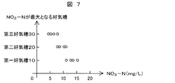
硝化工程においてNH4−Nは最終的にはNO3−Nに酸化する。そのため、NH4−Nの減少分はNO3−Nの増加分に概ね相当する。図7に、第三好気槽30のNO3−N濃度とNO2濃度が最大となる好気槽の関係を示す。第三好気槽30のNO3−N濃度が小さくなると、NO2−N濃度が最大となる好気槽が下流側になることが分かる。NO2−N濃度が最大となる好気槽の推定には、図7のグラフに基づいて作成したNO3−N濃度とNO2濃度が最大となる好気槽の関係を表す表を用いる。この表の一例を表3に示す。
In the nitrification step, NH 4 —N is finally oxidized to NO 3 —N. Therefore, the decrease amount of NH 4 —N substantially corresponds to the increase amount of NO 3 —N. FIG. 7 shows the relationship between the aerobic tank in which the NO 3 —N concentration and the NO 2 concentration in the third
表3に示す関係式は、時刻や季節などの環境条件や、ブロワ風量やMLSSといった運転条件によって変化するため、これらで場合分けした表を用いてもよい。 Since the relational expressions shown in Table 3 vary depending on environmental conditions such as time and season, and operating conditions such as blower air volume and MLSS, a table classified according to these cases may be used.
第三好気槽30よりも上流の生物反応槽(好気槽のほか嫌気槽,無酸素槽も含む)において計測したNO3−N濃度が小さくなると、NO2−N濃度が最大となる好気槽が下流側になるという傾向が得られる。実施例3では、好気槽のうち最も下流側に位置する第三好気槽30でNO3−N濃度を計測したが、上流側の生物反応槽でNO3−N濃度を計測し、NO2−N濃度が最大となる好気槽を推定しても良い。
When the NO 3 —N concentration measured in the biological reaction tank upstream of the third aerobic tank 30 (including anaerobic tanks, anaerobic tanks and anoxic tanks) is reduced, the NO 2 —N concentration is maximized. The tendency that an air tank becomes downstream is obtained. In Example 3, the NO 3 —N concentration was measured in the third
好気槽へのブロワ風量の制御については実施例1と同様である。また、実施例1ではブロワの全風量を変化させずに、弁の開度を変化させたが、DO一定制御や流入流量比例制御や硝化量制御などブロワの全風量を変動させる制御と組み合わせても良い。 The control of the blower air volume to the aerobic tank is the same as in the first embodiment. Further, in the first embodiment, the opening degree of the valve is changed without changing the total air volume of the blower. However, in combination with the control for changing the total air volume of the blower such as DO constant control, inflow flow rate proportional control, and nitrification amount control. Also good.
図8は本発明の実施例4の水処理設備の構成図である。本実施例の水処理設備は、実施例2のアンモニア性窒素計測器14のかわりに、第二好気槽20に酸化還元電位の検出手段である酸化還元電位計測器26が設置されている。
FIG. 8 is a configuration diagram of the water treatment facility according to the fourth embodiment of the present invention. In the water treatment facility of this embodiment, an oxidation-reduction
酸化還元電位は、ある酸化還元反応系における電子のやり取りの際に発生する電位のことで、有機物,DO,NH4−N,NO3−Nなどの濃度に影響を受ける。特にNH4−NとNO3−Nの濃度の影響は大きく、NH4−N濃度はORPと負の相関があり、NO3−N濃度とは正の相関がある。 The oxidation-reduction potential is a potential generated when electrons are exchanged in a certain oxidation-reduction reaction system, and is affected by the concentration of organic matter, DO, NH 4 —N, NO 3 —N, and the like. In particular, the influence of the concentrations of NH 4 -N and NO 3 -N is large, and the NH 4 -N concentration has a negative correlation with the ORP and has a positive correlation with the NO 3 -N concentration.
この結果、実施例2のアンモニア性窒素計測器あるいは実施例3の硝酸性窒素計測器と同様に酸化還元電位計測器により、NO2−N濃度が最大となる好気槽を推定できる。 As a result, the aerobic tank in which the NO 2 —N concentration is maximized can be estimated by the oxidation-reduction potential measuring instrument in the same manner as the ammonia nitrogen measuring instrument of Example 2 or the nitrate nitrogen measuring instrument of Example 3.
図9に第二好気槽20のORPとNO2濃度が最大となる好気槽の関係を示す。第二好気槽20のORPが小さくなると、NO2−N濃度が最大となる好気槽が下流側になることがわかる。NO2−N濃度が最大となる好気槽の推定には、図9のグラフに基づいて作成した、ORPとNO2濃度が最大となる好気槽の関係を表す表を用いる。この表の一例を表4に示す。
FIG. 9 shows the relationship between the ORP in the second
表4の関係式は、時刻や季節などの環境条件や、ブロワ風量やMLSSといった運転条件によって変化するため、これらを考慮した表を用いてもよい。 Since the relational expressions in Table 4 vary depending on environmental conditions such as time and season, and operating conditions such as blower air volume and MLSS, a table that takes these into consideration may be used.
第二好気槽20よりも上流あるいは下流の好気槽において計測したORPが小さくなると、NO2−Nが最大となる好気槽が下流側になるという傾向が得られる。実施例4では、第二好気槽20でORPを計測したが、上流側の好気槽あるいは下流側の好気槽でORPを計測し、NO2−N濃度が最大となる好気槽を推定しても良い。
When the ORP measured in the aerobic tank upstream or downstream of the second
好気槽へのブロワ風量の制御については実施例1と同様である。また、実施例1ではブロワの全風量を変化させずに、弁の開度を変化させたが、DO一定制御や流入流量比例制御や硝化量制御などブロワの全風量を変動させる制御と組み合わせても良い。 The control of the blower air volume to the aerobic tank is the same as in the first embodiment. Further, in the first embodiment, the opening degree of the valve is changed without changing the total air volume of the blower. However, in combination with the control for changing the total air volume of the blower such as DO constant control, inflow flow rate proportional control, and nitrification amount control. Also good.
図10は本発明の実施例5の水処理設備の構成図である。本実施例の水処理設備は、好気槽に計測器を設置していない。代わりに、NO2−N濃度最大槽条件入力手段43を備えており、NO2−N濃度最大槽条件入力手段43で入力された情報は演算手段41に送られる。 FIG. 10 is a configuration diagram of a water treatment facility according to the fifth embodiment of the present invention. The water treatment facility of this example does not have a measuring instrument installed in the aerobic tank. Instead, NO 2 —N concentration maximum tank condition input means 43 is provided, and information input by the NO 2 —N concentration maximum tank condition input means 43 is sent to the calculation means 41.
NO2−N濃度が最大となる好気槽は、時刻や季節や、流入下水100の水温や流入流量、ブロワ40で供給される全ブロワ風量や好気槽内のMLSSなどの下水処理場の環境条件や運転条件などと、NO2−Nが最大となる好気槽の関係を表すデータベースである表を用いることで推定できる。これらの表は過去の計測値から構築することができる。この表の一例を表5から表7に示す。
The aerobic tank in which the NO 2 -N concentration is maximized is the time and season, the temperature and flow rate of the
表5は、季節と時刻からNO2−N濃度が最大となる好気槽を推定する表である。この表の例では、流入するNH4−N濃度が小さい夜間にNO2−Nが最大となる好気槽は上流側になる。また、水温が上昇して硝化反応が促進される季節(7〜10月)にNO2−Nが最大となる好気槽は上流側になる。 Table 5 is a table for estimating the aerobic tank in which the NO 2 -N concentration is maximum from the season and time. In the example of this table, the aerobic tank in which NO 2 —N is maximized at night when the inflowing NH 4 —N concentration is small is upstream. In addition, the aerobic tank in which NO 2 -N is maximized is on the upstream side in the season (July to October) when the water temperature rises and the nitrification reaction is promoted.
表6は、水温と時刻からNO2−N濃度が最大となる好気槽を推定する表である。この表の例では、流入するNH4−N濃度が小さい夜間にNO2−Nが最大となる好気槽は上流側になる。また、硝化反応が促進される水温上昇時にNO2−Nが最大となる好気槽は上流側になる。 Table 6 is a table for estimating an aerobic tank in which the NO 2 —N concentration is maximum from the water temperature and time. In the example of this table, the aerobic tank in which NO 2 —N is maximized at night when the inflowing NH 4 —N concentration is small is upstream. Further, the aerobic tank in which NO 2 -N is maximized when the water temperature is increased to promote the nitrification reaction is upstream.
表7は、流入流量と全ブロワ風量からNO2−N濃度が最大となる好気槽を推定する表である。この表の例では、流入するNH4−Nの量が多くなる流入流量の増加時にNO2−Nが最大となる好気槽は下流側になる。また、硝化反応が促進する全ブロワ風量増加時にNO2−Nが最大となる好気槽は上流側になる。 Table 7 is a table for estimating the aerobic tank in which the NO 2 —N concentration is maximized from the inflow flow rate and the total blower air volume. In the example of this table, the aerobic tank in which NO 2 —N is maximized when the inflow rate increases so that the amount of NH 4 —N increases becomes downstream. In addition, the aerobic tank in which NO 2 -N is maximized when the total blower air volume is increased by the nitrification reaction is upstream.
実施例5では季節と時刻など二つの項目から表を作成し、NO2−N濃度が最大となる好気槽を推定したが、一つあるいは三つ以上の項目を組み合わせても良い。また、実施例1から実施例4で示した検出手段を組み合わせても良い。 In Example 5, a table was created from two items such as season and time, and the aerobic tank with the maximum NO 2 —N concentration was estimated. However, one or three or more items may be combined. Further, the detection means shown in the first to fourth embodiments may be combined.
好気槽へのブロワ風量の制御については実施例1と同様である。また、実施例1ではブロワの全風量を変化させずに、弁の開度のみを変化させたが、DO一定制御や流入流量比例制御や硝化量制御などブロワの全風量を変動させる制御と組み合わせても良い。 The control of the blower air volume to the aerobic tank is the same as in the first embodiment. Further, in the first embodiment, only the opening degree of the valve is changed without changing the total air volume of the blower. However, this is combined with the control for changing the total air volume of the blower such as DO constant control, inflow flow rate proportional control, and nitrification amount control. May be.
10 第一好気槽
11 第一散気管
12 第一弁
13 第一亜硝酸性窒素濃度計測器
14 アンモニア性窒素計測器
20 第二好気槽
21 第二散気管
22 第二弁
23 第二亜硝酸性窒素濃度計測器
26 酸化還元電位計測器
30 第三好気槽
31 第三散気管
32 第三弁
33 第三亜硝酸性窒素濃度計測器
35 硝酸性窒素計測器
40 ブロワ
41 演算手段
42 配分比制御手段
DESCRIPTION OF
Claims (7)
Priority Applications (1)
| Application Number | Priority Date | Filing Date | Title |
|---|---|---|---|
| JP2011008376A JP2012148231A (en) | 2011-01-19 | 2011-01-19 | Water treatment plant |
Applications Claiming Priority (1)
| Application Number | Priority Date | Filing Date | Title |
|---|---|---|---|
| JP2011008376A JP2012148231A (en) | 2011-01-19 | 2011-01-19 | Water treatment plant |
Publications (1)
| Publication Number | Publication Date |
|---|---|
| JP2012148231A true JP2012148231A (en) | 2012-08-09 |
Family
ID=46791053
Family Applications (1)
| Application Number | Title | Priority Date | Filing Date |
|---|---|---|---|
| JP2011008376A Pending JP2012148231A (en) | 2011-01-19 | 2011-01-19 | Water treatment plant |
Country Status (1)
| Country | Link |
|---|---|
| JP (1) | JP2012148231A (en) |
Cited By (2)
| Publication number | Priority date | Publication date | Assignee | Title |
|---|---|---|---|---|
| JP2016203077A (en) * | 2015-04-21 | 2016-12-08 | 帝人株式会社 | Multistage biological treatment apparatus |
| EP3067330B1 (en) * | 2015-03-11 | 2019-07-24 | Grundfos Holding A/S | Water treatment plant and process for the treatment of urea containing water |
-
2011
- 2011-01-19 JP JP2011008376A patent/JP2012148231A/en active Pending
Cited By (2)
| Publication number | Priority date | Publication date | Assignee | Title |
|---|---|---|---|---|
| EP3067330B1 (en) * | 2015-03-11 | 2019-07-24 | Grundfos Holding A/S | Water treatment plant and process for the treatment of urea containing water |
| JP2016203077A (en) * | 2015-04-21 | 2016-12-08 | 帝人株式会社 | Multistage biological treatment apparatus |
Similar Documents
| Publication | Publication Date | Title |
|---|---|---|
| Rodríguez-Caballero et al. | Minimizing N2O emissions and carbon footprint on a full-scale activated sludge sequencing batch reactor | |
| Bollon et al. | N2O emissions from full-scale nitrifying biofilters | |
| JP5140545B2 (en) | Air supply system and air supply method | |
| JP5733785B2 (en) | Waste water treatment method and waste water treatment equipment | |
| JP5188451B2 (en) | Water treatment equipment | |
| JP5075926B2 (en) | Sewage treatment apparatus and sewage treatment method | |
| Stenström et al. | Oxygen-induced dynamics of nitrous oxide in water and off-gas during the treatment of digester supernatant | |
| JP2005246136A (en) | Nitration method for ammonia nitrogen-containing water and treatment method therefor | |
| JP2010269255A (en) | Sewage treatment method | |
| JP5833791B1 (en) | Aeration control method for activated sludge | |
| JP6974795B2 (en) | Aeration air volume control method and equipment for aeration tanks in sewage treatment equipment | |
| JP2004275826A (en) | Sewage treatment plant water quality monitoring and controlling device | |
| JP5956372B2 (en) | Water treatment apparatus and water treatment method | |
| Weissenbacher et al. | NOx monitoring of a simultaneous nitrifying–denitrifying (SND) activated sludge plant at different oxidation reduction potentials | |
| KR102281691B1 (en) | Operation Apparatus and Method to Maximize Partial Nitritation by Controling Free Ammonia and Free Nitrous Acid Concentration in SBR Reactor for treating High Strength Nitrogen Wastewater | |
| JP2012148231A (en) | Water treatment plant | |
| JP6062328B2 (en) | Waste water treatment method, waste water treatment device, control method, control device, and program | |
| JP6391325B2 (en) | N2O suppression type water treatment method and treatment apparatus | |
| JP6334244B2 (en) | Water treatment process control system | |
| JP6375257B2 (en) | Water treatment equipment | |
| JP5656656B2 (en) | Water treatment equipment | |
| JP2015051389A (en) | Water treatment controller | |
| JP2013039577A (en) | Sewage treatment method | |
| JP2015029981A (en) | Nitrite-type nitrification method of ammoniac nitrogen-containing effluent | |
| KR102250418B1 (en) | Annamox reactor and water treatment method using the same |
Legal Events
| Date | Code | Title | Description |
|---|---|---|---|
| RD04 | Notification of resignation of power of attorney |
Free format text: JAPANESE INTERMEDIATE CODE: A7424 Effective date: 20120521 |