JP2012144992A - エアクリーナ - Google Patents
エアクリーナ Download PDFInfo
- Publication number
- JP2012144992A JP2012144992A JP2011001890A JP2011001890A JP2012144992A JP 2012144992 A JP2012144992 A JP 2012144992A JP 2011001890 A JP2011001890 A JP 2011001890A JP 2011001890 A JP2011001890 A JP 2011001890A JP 2012144992 A JP2012144992 A JP 2012144992A
- Authority
- JP
- Japan
- Prior art keywords
- cleaner
- fuel
- carburetor
- air cleaner
- outlet
- Prior art date
- Legal status (The legal status is an assumption and is not a legal conclusion. Google has not performed a legal analysis and makes no representation as to the accuracy of the status listed.)
- Granted
Links
Images

Classifications
-
- F—MECHANICAL ENGINEERING; LIGHTING; HEATING; WEAPONS; BLASTING
- F02—COMBUSTION ENGINES; HOT-GAS OR COMBUSTION-PRODUCT ENGINE PLANTS
- F02M—SUPPLYING COMBUSTION ENGINES IN GENERAL WITH COMBUSTIBLE MIXTURES OR CONSTITUENTS THEREOF
- F02M35/00—Combustion-air cleaners, air intakes, intake silencers, or induction systems specially adapted for, or arranged on, internal-combustion engines
- F02M35/02—Air cleaners
- F02M35/024—Air cleaners using filters, e.g. moistened
-
- F—MECHANICAL ENGINEERING; LIGHTING; HEATING; WEAPONS; BLASTING
- F02—COMBUSTION ENGINES; HOT-GAS OR COMBUSTION-PRODUCT ENGINE PLANTS
- F02M—SUPPLYING COMBUSTION ENGINES IN GENERAL WITH COMBUSTIBLE MIXTURES OR CONSTITUENTS THEREOF
- F02M35/00—Combustion-air cleaners, air intakes, intake silencers, or induction systems specially adapted for, or arranged on, internal-combustion engines
- F02M35/02—Air cleaners
- F02M35/04—Air cleaners specially arranged with respect to engine, to intake system or specially adapted to vehicle; Mounting thereon ; Combinations with other devices
-
- F—MECHANICAL ENGINEERING; LIGHTING; HEATING; WEAPONS; BLASTING
- F02—COMBUSTION ENGINES; HOT-GAS OR COMBUSTION-PRODUCT ENGINE PLANTS
- F02M—SUPPLYING COMBUSTION ENGINES IN GENERAL WITH COMBUSTIBLE MIXTURES OR CONSTITUENTS THEREOF
- F02M17/00—Carburettors having pertinent characteristics not provided for in, or of interest apart from, the apparatus of preceding main groups F02M1/00 - F02M15/00
- F02M17/34—Other carburettors combined or associated with other apparatus, e.g. air filters
-
- F—MECHANICAL ENGINEERING; LIGHTING; HEATING; WEAPONS; BLASTING
- F02—COMBUSTION ENGINES; HOT-GAS OR COMBUSTION-PRODUCT ENGINE PLANTS
- F02M—SUPPLYING COMBUSTION ENGINES IN GENERAL WITH COMBUSTIBLE MIXTURES OR CONSTITUENTS THEREOF
- F02M35/00—Combustion-air cleaners, air intakes, intake silencers, or induction systems specially adapted for, or arranged on, internal-combustion engines
- F02M35/10—Air intakes; Induction systems
- F02M35/1015—Air intakes; Induction systems characterised by the engine type
- F02M35/1017—Small engines, e.g. for handheld tools, or model engines; Single cylinder engines
-
- F—MECHANICAL ENGINEERING; LIGHTING; HEATING; WEAPONS; BLASTING
- F02—COMBUSTION ENGINES; HOT-GAS OR COMBUSTION-PRODUCT ENGINE PLANTS
- F02M—SUPPLYING COMBUSTION ENGINES IN GENERAL WITH COMBUSTIBLE MIXTURES OR CONSTITUENTS THEREOF
- F02M35/00—Combustion-air cleaners, air intakes, intake silencers, or induction systems specially adapted for, or arranged on, internal-combustion engines
- F02M35/10—Air intakes; Induction systems
- F02M35/1015—Air intakes; Induction systems characterised by the engine type
- F02M35/10196—Carburetted engines
Landscapes
- Engineering & Computer Science (AREA)
- Chemical & Material Sciences (AREA)
- Combustion & Propulsion (AREA)
- Mechanical Engineering (AREA)
- General Engineering & Computer Science (AREA)
- Filtering Of Dispersed Particles In Gases (AREA)
- Lubrication Details And Ventilation Of Internal Combustion Engines (AREA)
Abstract
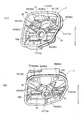
【解決手段】気化器側に位置するクリーナ底壁15Aに設けられたクリーナ出口20の近傍にそれを囲繞するように形成され、気化器から吹き返された混合燃料を溜める燃料溜部30と、クリーナ出口20を介してエアクリーナ内に吹き返された混合燃料がフィルタ側ではなく燃料溜部30側に向かうように誘導する吹き返し誘導部材19と、燃料溜部30に溜まる燃料を吸気負圧を利用して気化器側へ還流させるべく、一端が燃料溜部30に連通するとともに、他端がクリーナ出口20に連通する戻し流路41、42、43、44とを備え、この戻し流路41、42、43、44は、上端面がクリーナ出口20に向かって下り勾配のスロープ面とされ、クリーナ出口20を中心として放射状に設けられている。
【選択図】図1
Description
前記戻し流路は、好ましくは、前記クリーナ底壁に立設された、上端面が前記クリーナ出口に向かって下り勾配のスロープ面とされた流路形成板部を含んで構成される。
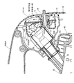
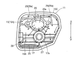
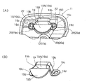
図1(A)は、本発明に係るエアクリーナの一実施例のケース部分を示す平面図、図1(B)は、図1(A)に示されるケースに吹き返し誘導部材を取り付けた状態を示す平面図、図2(A)は、図1(A)のP方向斜視図、図2(B)は、図1(A)のR方向斜視図である。
11 ケース
12 フィルタ
13 カバー
19 吹き返し誘導部材
20 クリーナ出口
30 燃料溜部
31、32 堰状板部
41、42、43、44 戻し流路
41A、42A、43A、44A 流路形成板部
Claims (3)
- エンジンの吸気系における気化器の直上流に配設されるエアクリーナであって、
前記気化器側に位置するクリーナ底壁に設けられたクリーナ出口の近傍にそれを囲繞するように形成され、前記気化器から吹き返された混合燃料を溜めておく燃料溜部と、前記クリーナ出口を介して当該エアクリーナ内に吹き返された混合燃料がフィルタ側ではなく前記燃料溜部側に向かうように誘導する吹き返し誘導部材と、前記燃料溜部に溜まる燃料を吸気負圧を利用して前記気化器側へ還流させるべく、一端が前記クリーナ出口に連通するとともに、他端が前記燃料溜部に連通する戻し流路とを備え、
前記戻し流路は、前記クリーナ出口を中心として放射状に複数個形成されていることを特徴とするエアクリーナ。 - 前記燃料溜部は、前記クリーナ底壁に立設された堰状板部を含んで構成されていることを特徴とする請求項1に記載のエアクリーナ。
- 前記戻し流路は、前記クリーナ底壁に立設された、上端面が前記クリーナ出口に向かって下り勾配のスロープ面とされた流路形成板部を含んで構成されていることを特徴とする請求項1又は2に記載のエアクリーナ。
Priority Applications (3)
| Application Number | Priority Date | Filing Date | Title |
|---|---|---|---|
| JP2011001890A JP5685445B2 (ja) | 2011-01-07 | 2011-01-07 | エアクリーナ |
| EP12000031.0A EP2474732B1 (en) | 2011-01-07 | 2012-01-04 | Air cleaner |
| US13/344,920 US8591618B2 (en) | 2011-01-07 | 2012-01-06 | Air cleaner |
Applications Claiming Priority (1)
| Application Number | Priority Date | Filing Date | Title |
|---|---|---|---|
| JP2011001890A JP5685445B2 (ja) | 2011-01-07 | 2011-01-07 | エアクリーナ |
Publications (2)
| Publication Number | Publication Date |
|---|---|
| JP2012144992A true JP2012144992A (ja) | 2012-08-02 |
| JP5685445B2 JP5685445B2 (ja) | 2015-03-18 |
Family
ID=45497795
Family Applications (1)
| Application Number | Title | Priority Date | Filing Date |
|---|---|---|---|
| JP2011001890A Expired - Fee Related JP5685445B2 (ja) | 2011-01-07 | 2011-01-07 | エアクリーナ |
Country Status (3)
| Country | Link |
|---|---|
| US (1) | US8591618B2 (ja) |
| EP (1) | EP2474732B1 (ja) |
| JP (1) | JP5685445B2 (ja) |
Cited By (2)
| Publication number | Priority date | Publication date | Assignee | Title |
|---|---|---|---|---|
| JP2015203357A (ja) * | 2014-04-14 | 2015-11-16 | 株式会社マキタ | 携帯型作業機のキャブレタ取付け構造及び取付け方法 |
| WO2019012925A1 (ja) * | 2017-07-12 | 2019-01-17 | 川崎重工業株式会社 | 吹返し燃料の吸戻し構造 |
Families Citing this family (3)
| Publication number | Priority date | Publication date | Assignee | Title |
|---|---|---|---|---|
| JP6407550B2 (ja) * | 2014-04-03 | 2018-10-17 | 株式会社やまびこ | 吹き返し防止構造 |
| DE202016102198U1 (de) * | 2016-04-26 | 2017-07-28 | Makita Corporation | Luftfiltereinrichtung zur Filterung einer Ansaugluft einer Brennkarftmaschine, insbesondere für ein handhaltbares Kleinarbeitsgerät |
| EP3456495B1 (de) * | 2017-09-15 | 2021-06-30 | Andreas Stihl AG & Co. KG | Handgeführtes arbeitsgerät |
Citations (1)
| Publication number | Priority date | Publication date | Assignee | Title |
|---|---|---|---|---|
| JPS414474Y1 (ja) * | 1964-08-25 | 1966-03-15 |
Family Cites Families (10)
| Publication number | Priority date | Publication date | Assignee | Title |
|---|---|---|---|---|
| DE3424774C2 (de) | 1984-07-05 | 1994-04-07 | Stihl Maschf Andreas | Zweitaktmotor |
| JPS6375559U (ja) | 1986-11-04 | 1988-05-19 | ||
| DE4427739A1 (de) * | 1994-08-05 | 1996-02-08 | Stihl Maschf Andreas | Ansaugluftfilter |
| DE10016430B4 (de) * | 2000-04-01 | 2016-02-18 | Andreas Stihl Ag & Co. | Luftfiltergehäuse mit Pralltopf |
| JP2005083241A (ja) * | 2003-09-08 | 2005-03-31 | Kioritz Corp | 携帯型動力作業機 |
| JP4340504B2 (ja) * | 2003-09-19 | 2009-10-07 | 川崎重工業株式会社 | 背負式作業機 |
| DE10358030A1 (de) * | 2003-12-11 | 2005-07-07 | Hilti Ag | Zyklonabscheider |
| US7776119B2 (en) * | 2004-02-04 | 2010-08-17 | Notaras John A | Air filter arrangement |
| DE102005000126A1 (de) * | 2005-09-22 | 2007-03-29 | Hilti Ag | Schnellkupplungsanschlussteil mit Filter |
| US7628834B2 (en) * | 2007-08-10 | 2009-12-08 | De Poan Pneumatic Corp. | Compressed air filter assembly for nail gun |
-
2011
- 2011-01-07 JP JP2011001890A patent/JP5685445B2/ja not_active Expired - Fee Related
-
2012
- 2012-01-04 EP EP12000031.0A patent/EP2474732B1/en not_active Not-in-force
- 2012-01-06 US US13/344,920 patent/US8591618B2/en not_active Expired - Fee Related
Patent Citations (1)
| Publication number | Priority date | Publication date | Assignee | Title |
|---|---|---|---|---|
| JPS414474Y1 (ja) * | 1964-08-25 | 1966-03-15 |
Cited By (3)
| Publication number | Priority date | Publication date | Assignee | Title |
|---|---|---|---|---|
| JP2015203357A (ja) * | 2014-04-14 | 2015-11-16 | 株式会社マキタ | 携帯型作業機のキャブレタ取付け構造及び取付け方法 |
| WO2019012925A1 (ja) * | 2017-07-12 | 2019-01-17 | 川崎重工業株式会社 | 吹返し燃料の吸戻し構造 |
| JP2019019690A (ja) * | 2017-07-12 | 2019-02-07 | 川崎重工業株式会社 | 吹返し燃料の吸戻し構造 |
Also Published As
| Publication number | Publication date |
|---|---|
| US8591618B2 (en) | 2013-11-26 |
| EP2474732B1 (en) | 2015-04-01 |
| EP2474732A1 (en) | 2012-07-11 |
| JP5685445B2 (ja) | 2015-03-18 |
| US20120174889A1 (en) | 2012-07-12 |
Similar Documents
| Publication | Publication Date | Title |
|---|---|---|
| JP4381913B2 (ja) | 燃料タンク装置 | |
| US6295953B1 (en) | Portable power working machine | |
| JP5685445B2 (ja) | エアクリーナ | |
| US7475681B2 (en) | Breather apparatus in combustion engine | |
| JP2012149635A (ja) | エンジン作業機 | |
| CN103370504A (zh) | 曲轴箱和内燃机 | |
| JP4392300B2 (ja) | シリンダヘッドの冷却構造 | |
| JP6407550B2 (ja) | 吹き返し防止構造 | |
| CN101865052B (zh) | 空气过滤器单元 | |
| JP6541559B2 (ja) | エアクリーナ | |
| US20170311551A1 (en) | Backpack Power Tool with a Drive Motor and a Blower Driven by the Drive Motor | |
| US20160265491A1 (en) | Power working machine | |
| JP6211388B2 (ja) | エンジン作業機の吸気装置 | |
| JP2007120482A (ja) | ブローバイガス環流装置 | |
| JPH11294271A (ja) | エアクリーナ | |
| JP4280150B2 (ja) | エンジンのエアクリーナ | |
| CN116096471A (zh) | 具有倾斜挡板的全向流通式导流构件 | |
| JP2009019599A (ja) | エンジン | |
| CN114251156A (zh) | 油气分离器 | |
| US11162463B2 (en) | Structure for suctioning back blow-back fuel | |
| JPS5913332Y2 (ja) | 内燃機関の吸気装置 | |
| JPH06917Y2 (ja) | 茶刈機用エンジン部の除塵装置 | |
| WO2007132915A1 (ja) | 携帯型作業機 | |
| CA2979032A1 (en) | Oil mist separation mechanism for internal combustion engine | |
| JP2012163088A (ja) | 携帯型作業機 |
Legal Events
| Date | Code | Title | Description |
|---|---|---|---|
| A621 | Written request for application examination |
Free format text: JAPANESE INTERMEDIATE CODE: A621 Effective date: 20131114 |
|
| TRDD | Decision of grant or rejection written | ||
| A01 | Written decision to grant a patent or to grant a registration (utility model) |
Free format text: JAPANESE INTERMEDIATE CODE: A01 Effective date: 20150106 |
|
| A61 | First payment of annual fees (during grant procedure) |
Free format text: JAPANESE INTERMEDIATE CODE: A61 Effective date: 20150119 |
|
| R150 | Certificate of patent or registration of utility model |
Ref document number: 5685445 Country of ref document: JP Free format text: JAPANESE INTERMEDIATE CODE: R150 |
|
| R250 | Receipt of annual fees |
Free format text: JAPANESE INTERMEDIATE CODE: R250 |
|
| R250 | Receipt of annual fees |
Free format text: JAPANESE INTERMEDIATE CODE: R250 |
|
| R250 | Receipt of annual fees |
Free format text: JAPANESE INTERMEDIATE CODE: R250 |
|
| R250 | Receipt of annual fees |
Free format text: JAPANESE INTERMEDIATE CODE: R250 |
|
| R250 | Receipt of annual fees |
Free format text: JAPANESE INTERMEDIATE CODE: R250 |
|
| R250 | Receipt of annual fees |
Free format text: JAPANESE INTERMEDIATE CODE: R250 |
|
| LAPS | Cancellation because of no payment of annual fees |