JP2012144992A - Air cleaner - Google Patents
Air cleaner Download PDFInfo
- Publication number
- JP2012144992A JP2012144992A JP2011001890A JP2011001890A JP2012144992A JP 2012144992 A JP2012144992 A JP 2012144992A JP 2011001890 A JP2011001890 A JP 2011001890A JP 2011001890 A JP2011001890 A JP 2011001890A JP 2012144992 A JP2012144992 A JP 2012144992A
- Authority
- JP
- Japan
- Prior art keywords
- cleaner
- fuel
- carburetor
- air cleaner
- outlet
- Prior art date
- Legal status (The legal status is an assumption and is not a legal conclusion. Google has not performed a legal analysis and makes no representation as to the accuracy of the status listed.)
- Granted
Links
Images

Classifications
-
- F—MECHANICAL ENGINEERING; LIGHTING; HEATING; WEAPONS; BLASTING
- F02—COMBUSTION ENGINES; HOT-GAS OR COMBUSTION-PRODUCT ENGINE PLANTS
- F02M—SUPPLYING COMBUSTION ENGINES IN GENERAL WITH COMBUSTIBLE MIXTURES OR CONSTITUENTS THEREOF
- F02M35/00—Combustion-air cleaners, air intakes, intake silencers, or induction systems specially adapted for, or arranged on, internal-combustion engines
- F02M35/02—Air cleaners
- F02M35/024—Air cleaners using filters, e.g. moistened
-
- F—MECHANICAL ENGINEERING; LIGHTING; HEATING; WEAPONS; BLASTING
- F02—COMBUSTION ENGINES; HOT-GAS OR COMBUSTION-PRODUCT ENGINE PLANTS
- F02M—SUPPLYING COMBUSTION ENGINES IN GENERAL WITH COMBUSTIBLE MIXTURES OR CONSTITUENTS THEREOF
- F02M35/00—Combustion-air cleaners, air intakes, intake silencers, or induction systems specially adapted for, or arranged on, internal-combustion engines
- F02M35/02—Air cleaners
- F02M35/04—Air cleaners specially arranged with respect to engine, to intake system or specially adapted to vehicle; Mounting thereon ; Combinations with other devices
-
- F—MECHANICAL ENGINEERING; LIGHTING; HEATING; WEAPONS; BLASTING
- F02—COMBUSTION ENGINES; HOT-GAS OR COMBUSTION-PRODUCT ENGINE PLANTS
- F02M—SUPPLYING COMBUSTION ENGINES IN GENERAL WITH COMBUSTIBLE MIXTURES OR CONSTITUENTS THEREOF
- F02M17/00—Carburettors having pertinent characteristics not provided for in, or of interest apart from, the apparatus of preceding main groups F02M1/00 - F02M15/00
- F02M17/34—Other carburettors combined or associated with other apparatus, e.g. air filters
-
- F—MECHANICAL ENGINEERING; LIGHTING; HEATING; WEAPONS; BLASTING
- F02—COMBUSTION ENGINES; HOT-GAS OR COMBUSTION-PRODUCT ENGINE PLANTS
- F02M—SUPPLYING COMBUSTION ENGINES IN GENERAL WITH COMBUSTIBLE MIXTURES OR CONSTITUENTS THEREOF
- F02M35/00—Combustion-air cleaners, air intakes, intake silencers, or induction systems specially adapted for, or arranged on, internal-combustion engines
- F02M35/10—Air intakes; Induction systems
- F02M35/1015—Air intakes; Induction systems characterised by the engine type
- F02M35/1017—Small engines, e.g. for handheld tools, or model engines; Single cylinder engines
-
- F—MECHANICAL ENGINEERING; LIGHTING; HEATING; WEAPONS; BLASTING
- F02—COMBUSTION ENGINES; HOT-GAS OR COMBUSTION-PRODUCT ENGINE PLANTS
- F02M—SUPPLYING COMBUSTION ENGINES IN GENERAL WITH COMBUSTIBLE MIXTURES OR CONSTITUENTS THEREOF
- F02M35/00—Combustion-air cleaners, air intakes, intake silencers, or induction systems specially adapted for, or arranged on, internal-combustion engines
- F02M35/10—Air intakes; Induction systems
- F02M35/1015—Air intakes; Induction systems characterised by the engine type
- F02M35/10196—Carburetted engines
Landscapes
- Engineering & Computer Science (AREA)
- Chemical & Material Sciences (AREA)
- Combustion & Propulsion (AREA)
- Mechanical Engineering (AREA)
- General Engineering & Computer Science (AREA)
- Filtering Of Dispersed Particles In Gases (AREA)
- Lubrication Details And Ventilation Of Internal Combustion Engines (AREA)
Abstract
Description
本発明は、エンジンの吸気系における気化器の直上流に配設されるエアクリーナに係り、特に、気化器から吹き返される混合燃料(ガソリンと潤滑用オイル)に起因する不具合・トラブルを抑制ないし低減し得るようにされたエアクリーナに関する。 The present invention relates to an air cleaner disposed immediately upstream of a carburetor in an intake system of an engine, and particularly suppresses or reduces problems and troubles caused by mixed fuel (gasoline and lubricating oil) blown back from the carburetor. It is related with the air cleaner made to obtain.
例えば、チェーンソーや刈払機等の携帯型動力作業機にあっては、通常、本体ハウジング内に、ソーチェーン等の作業部を駆動するための動力源として、排気量25〜100cc程度の小型空冷内燃機関である2サイクルガソリンエンジンが搭載されており、該エンジンの吸気系には燃料供給・調量手段としての気化器が配備されるとともに、この気化器の直上流には、吸入される外気から塵埃を取り除いて清浄化するためのエアクリーナが配設されている。 For example, in a portable power working machine such as a chain saw or a brush cutter, a small air-cooled internal combustion engine having a displacement of about 25 to 100 cc is usually used as a power source for driving a working unit such as a saw chain in the main body housing. The engine is equipped with a two-cycle gasoline engine, and a carburetor as a fuel supply / metering means is provided in the intake system of the engine, and from the outside air sucked in immediately upstream of the carburetor. An air cleaner for removing dust and cleaning is provided.
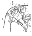
以下、上記エアクリーナの従来例を、チェーンソーの後部及びそれに搭載された掃気口を左右に2つずつ計4つ有する反転掃気式の2サイクルガソリンエンジンの一部と共に示す図3を参照しながら説明する。 Hereinafter, a conventional example of the air cleaner will be described with reference to FIG. 3 showing a rear part of a chain saw and a part of a reverse scavenging type two-cycle gasoline engine having four scavenging ports mounted on the right and left. .
図示のチェーンソー50においては、本体ハウジング52の上面部及び後部にまたがって、スロットルロックレバーやスロットルトリガーが組み込まれた横向きL形のトップハンドル54が配設され、本体ハウジング52内にエンジン60により駆動される冷却ファン(図示せず)が配設され、この冷却ファンにより本体ハウジング52内に吸入された空気の一部を、前記トップハンドル54及び本体ハウジング52の後部に配設された前記エアクリーナ10’及び気化器65を介してエンジン60のシリンダ62内に吸入させるようになっている。
In the illustrated
エンジン60は、本体ハウジング52内に、横置きで、その吸気口63を上側にしかつ頭部(燃焼室)64を機体後方に向けて搭載されており、前記吸気口63より上流側に合成ゴム材よりなる吸振性通気管66を介して前記気化器65が連結されるとともに、該気化器65の直上流にエアクリーナ10’が連接されている。
The
エアクリーナ10’は、概略へ字状断面の底壁15[気化器65側(上側)の底壁15Aとクリーナ入口16側(下側)の底壁15B]及び外周側壁15Cを持つ合成樹脂製のケース11と、該ケース11の上面開口を覆うように被せられた厚板状のフィルタ(濾過エレメント)12と、該フィルタ12を前記ケース11との間に挟み込むように被せられた合成樹脂製のカバー13と、このカバー13を取着すべく、ケース11における気化器側底壁15Aとクリーナ入口側底壁15Bとの境目辺りに形成された雌ねじ部17にねじ込まれたねじ部材18と、を備え、前記ねじ部材18を弛めれば、カバー13及びフィルタ12を取り外すことができるようになっている。なお、雌ねじ部17は、その上部(ボス部17a)が底壁15(15A、15B)から上方に突出せしめられている。
The air cleaner 10 'is made of a synthetic resin having a bottom wall 15 [a
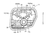
また、前記エアクリーナ10’のケース11部分が図4に示されているように、ケース11の気化器側底壁15Aには、気化器65における内部通路67の吸入口67aに連なるようにクリーナ出口20が設けられている。クリーナ出口20は、その上端部(ボス部20a)が底壁15A上面より若干上側に突出せしめられている。底壁15A上には、気化器65から吹き返される混合燃料(後述する)をフィルタ12側に向かわせないようにするための板金製の吹き返し誘導部材19が配設されている。
Further, as shown in FIG. 4, the
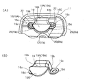
この誘導部材19は、図5(A)に取付状態の平面図、(B)に斜視図が示されているように、前記クリーナ出口20の中央上に跨る逆リップ溝形状の折曲板部19Aと該折曲板部19Aの上板部19aから雌ねじ部17側にやや下向きに折れ曲がって延設された三日月状板部19Bとからなり、折曲板部19Aの両側板部19b、19bの下端には、外側に折り曲がるねじ止め板部19c、19cが設けられており、止めねじ22が、ねじ止め板部19c、19cに設けられた通し穴19d及びケース11の底壁15Aに設けられたボス部29a付き挿通穴29、29を介して気化器65にねじ込まれて、吹き返し誘導部材19とケース11とが気化器65に共締め固定されている。
As shown in FIG. 5A, the
また、ケース11のクリーナ入口側底壁15Bには、気化器65から吹き返された燃料を集めて溜める燃料溜部25を画成すべく、立上板部27、28が設けられている。
In addition, rising
ところで、上記した如くのエンジン60の吸気系においては、何ら対策を講じなければ、吸気口63からの吹き返しにより、気化器65で一旦は霧化された混合燃料(ガソリンと潤滑用オイル)がクリーナ出口20を介してケース11内に吹き返される。この吹き返し流を、図4(A)に点破線矢印で示す。クリーナ出口20を介してケース11内に吹き返された混合燃料は、吹き返し誘導部材19に誘導されて(図3の破線矢印)、ケース11の内壁面(外周側壁15Cや底壁15)等を伝って前記燃料溜部25に集められて溜められるが、その一部はそのままフィルタ12に付着する。また、溜められた混合燃料の一部は吹き返し後の吸入時に吸気負圧によりクリーナ出口20側に吸引されて気化器65に還流されるが、その一部は燃料溜部25に残り、燃料溜部25から溢れ出るなどしてフィルタ12に付着する。
By the way, in the intake system of the
フィルタ12に付着した混合燃料は、ガソリンだけが気化し、オイル分のみがケース11及びフィルタ12に残り、その結果、フィルタ12の通気抵抗が増え(吸入空気量減少)、気化器65のノズルに掛かるブースト圧が増加し、燃料流量が増え、燃焼に供される混合気が過濃状態となり、出力が低下し、作業性が悪化するばかりか、作業者は頻繁にフィルタ12のメンテナンス(交換等)を強いられる。例えば、上記したエンジン(排気量27cc)においては、20時間程度使用すると、フィルタ12のメンテナンスが必要となる。そのメンテナンスを怠った場合、ケース11から飽和したオイルにより、機体が汚れるだけでなく、土壌汚染を引き起こす(刈払機等は、特に米処でそういった不具合が嫌がられる)。
As for the mixed fuel adhering to the
上記のように気化器から吹き返される混合燃料による不具合・トラブルを抑制ないし低減すべく、従来より、例えば特許文献1、2等に見られるように、気化器から吹き返された混合燃料を集めて溜める燃料溜部と、該燃料溜部に溜まる燃料を吸気負圧を利用して気化器側へ還流させるための戻し流路とを設けること等が提案されているが、それだけでは、特に、機体(エンジン・エアクリーナ)の姿勢変化が大きくなりやすい(傾斜、転倒等をしやすい)チェーンソーや刈払機等の携帯型作業機においては、前記不具合・トラブルを十分には解消できない。 In order to suppress or reduce the problems and troubles caused by the mixed fuel blown back from the carburetor as described above, the mixed fuel blown back from the carburetor is collected and stored, as seen in, for example, Patent Documents 1 and 2, etc. Providing a fuel reservoir and a return flow path for returning the fuel accumulated in the fuel reservoir to the carburetor using intake negative pressure has been proposed. In portable work machines such as chainsaws and brush cutters, which tend to have a large change in attitude of the engine / air cleaner (easily tilted or overturned), the problems and troubles cannot be solved sufficiently.
本発明は、上記事情に鑑みてなされたもので、その目的とするところは、気化器から吹き返される混合燃料に起因する不具合・トラブルを抑制ないし低減し得て、フィルタの長寿命化・メンテナンス頻度の低減等を図ることのできるエアクリーナを提供することにある。 The present invention has been made in view of the above circumstances, and the object of the present invention is to suppress or reduce problems and troubles caused by the mixed fuel blown back from the carburetor, to extend the life of the filter and to maintain the filter. An object of the present invention is to provide an air cleaner capable of reducing the above-mentioned.
前記の目的を達成すべく、本発明に係るエアクリーナは、基本的には、エンジンの吸気系における気化器の直上流に配設されるもので、前記気化器側に位置するクリーナ底壁に設けられたクリーナ出口の近傍に形成され、前記気化器から吹き返された混合燃料を集めて溜める燃料溜部と、前記クリーナ出口を介して当該エアクリーナ内に吹き返された混合燃料がフィルタ側ではなく前記燃料溜部側に向かうように誘導する吹き返し誘導部材と、前記燃料溜部に溜まる燃料を吸気負圧を利用して前記気化器側へ還流させるべく、一端が前記燃料溜部に連通するとともに、他端が前記クリーナ出口に連通する戻し流路とを備え、前記戻し流路は、前記クリーナ出口を中心として放射状に複数個形成されていることを特徴としている。 In order to achieve the above object, the air cleaner according to the present invention is basically disposed immediately upstream of the carburetor in the intake system of the engine, and is provided on the bottom wall of the cleaner located on the carburetor side. A fuel reservoir for collecting and storing the mixed fuel blown back from the carburetor, and the mixed fuel blown back into the air cleaner via the cleaner outlet instead of the filter side. A blow-back induction member that guides toward the reservoir side, and one end communicates with the fuel reservoir portion in order to recirculate the fuel accumulated in the fuel reservoir portion to the carburetor side using intake negative pressure, And a return flow path whose end communicates with the cleaner outlet, and a plurality of the return flow paths are formed radially around the cleaner outlet.
前記燃料溜部は、好ましくは、前記クリーナ底壁に立設された堰状板部を含んで構成される。
前記戻し流路は、好ましくは、前記クリーナ底壁に立設された、上端面が前記クリーナ出口に向かって下り勾配のスロープ面とされた流路形成板部を含んで構成される。
The fuel reservoir preferably includes a dam-like plate portion standing on the cleaner bottom wall.
The return flow path preferably includes a flow path forming plate portion that is provided upright on the bottom wall of the cleaner and has an upper end surface that is a slope surface having a downward slope toward the outlet of the cleaner.
本発明に係るエアクリーナでは、気化器から吹き返された混合燃料を集めて溜める燃料溜部に加えて、一端が燃料溜部に連通するとともに、他端がクリーナ出口に連通する戻し流路が、クリーナ出口を中心として放射状に複数個形成されているので、燃料溜部に溜まる混合燃料は、その後、吸気負圧により、前記放射状に複数個形成された戻し流路を通じて効率よく気化器側に還流せしめられる。 In the air cleaner according to the present invention, in addition to the fuel reservoir portion that collects and collects the mixed fuel blown back from the vaporizer, a return flow path having one end communicating with the fuel reservoir portion and the other end communicating with the cleaner outlet is provided in the cleaner. Since a plurality of fuels are formed radially around the outlet, the mixed fuel stored in the fuel reservoir is then efficiently returned to the carburetor side by the intake negative pressure through the plurality of radially formed return passages. It is done.
そのため、フィルタに付着する混合燃料量が従来例のものに比して大幅に低減され、その結果、気化器から吹き返される混合燃料に起因する不具合・トラブルを効果的に抑制ないし低減し得て、フィルタの長寿命化・メンテナンス頻度の低減等を図ることができる。 Therefore, the amount of mixed fuel adhering to the filter is greatly reduced as compared with the conventional example, and as a result, problems and troubles caused by the mixed fuel blown back from the vaporizer can be effectively suppressed or reduced, It is possible to extend the filter life and reduce the maintenance frequency.
また、戻し流路を前記クリーナ底壁に立設された流路形成板部で構成することにより、当該戻し流路が吸入空気を整流する整流板の役目も果たすことになり、そのため、出力低下等を招くことなく、フィルタへの燃料付着量を低減できる。 In addition, by configuring the return flow path with the flow path forming plate portion standing on the cleaner bottom wall, the return flow path also serves as a rectifying plate for rectifying the intake air, so that the output is reduced. The amount of fuel adhering to the filter can be reduced without incurring, for example.
また、戻し流路が放射状に形成されるので、作業機(エンジン、当該エアクリーナ)がどのような姿勢になっても(大きく傾斜したり、転倒したりしても)、吹き返された混合燃料を確実に気化器に戻すことができる。 In addition, since the return flow path is formed in a radial shape, the mixed fuel that has been blown back can be used regardless of the posture of the work implement (engine, air cleaner). It can be reliably returned to the vaporizer.
以下、本発明の実施形態を図面を参照しながら説明する。
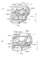
図1(A)は、本発明に係るエアクリーナの一実施例のケース部分を示す平面図、図1(B)は、図1(A)に示されるケースに吹き返し誘導部材を取り付けた状態を示す平面図、図2(A)は、図1(A)のP方向斜視図、図2(B)は、図1(A)のR方向斜視図である。
Embodiments of the present invention will be described below with reference to the drawings.
FIG. 1A is a plan view showing a case portion of an embodiment of an air cleaner according to the present invention, and FIG. 1B shows a state in which a blow back guide member is attached to the case shown in FIG. FIG. 2A is a plan view of FIG. 1A, and FIG. 2B is a perspective view of FIG. 1A in the R direction.
本実施例のエアクリーナ10は、前述した図3、図4に示される従来例のエアクリーナ10’と基本構成、すなわち、ケース11、フィルタ12、カバー13、ねじ部材18、誘導部材19等を備えていることは同じであり、ケース11の底壁15上の構成が異なるだけであるので、従来例のエアクリーナ10’の各部に対応する部分には共通の符号を付して重複説明を省略し、以下においては、相異点を重点的に説明する。
The
本実施例のエアクリーナ10のケース11においては、気化器65から吹き返された混合燃料を集めて溜めるべく、気化器側底壁15Aに設けられたクリーナ出口20の近傍に、それを囲繞するように燃料溜部30が形成されている。燃料溜部30は、主として、気化器側底壁15Aと、その外周部分を形成する外周側壁15Cと、気化器側底壁15Aとクリーナ入口側底壁15Bとの間を仕切るように底壁15上にく字ないし横倒しハ字状に上下対称的に立設された2つの堰状板部31、32とから形成されている。堰状板部31、32は、それぞれ一端側が外周側壁15Cに連なり、他端側が雌ねじ部17のボス部17aに連なっており、吹き返された混合燃料が底壁15Aから底壁15B側に流出しないように堰き止める構成となっている。なお、燃料溜部30には、前記した誘導部材19をねじ止めするための挿通穴29、29のボス部29a付近と外周側壁15Cとを結ぶようにリブ状仕切板部36、37、38も立設されている。リブ状仕切板部36、37、38は、その高さがクリーナ出口20のボス部20aや挿通穴29、29のボス部29aの高さと略同じとなっている。
In the
また、燃料溜部30には、該燃料溜部30に溜まる燃料を吸気負圧を利用して気化器65側へ還流させるべく、一端がクリーナ出口20に連通するとともに、他端が燃料溜部30に連通する戻し流路41、42、43、44が設けられている。
In addition, one end of the
前記戻し流路41、42、43、44は、それぞれクリーナ出口20を中心として放射状に立設された、上端面がクリーナ出口20に向かって下り勾配の平らな(Rなどが施されていない)スロープ面とされた流路形成板部41A、42A、43A、44Aを含んで構成されている。各流路形成板部41A、42A、43A、44Aは、一端がクリーナ出口20に連なり、そのスロープ面がクリーナ出口20のボス部20aより上側に位置せしめられている。流路形成板部41Aの他端は、堰状板部31に連なり、流路形成板部42Aの他端は、堰状板部32に連なり、流路形成板部43Aの他端は、外周側壁15Cに連なり、流路形成板部44Aの他端は、雌ねじ部17のボス部17aに連なっている。
The
このような構成とされた本実施例のエアクリーナ10においては、吸気口63からの吹き返しにより、気化器65で一旦は霧化された混合燃料(ガソリンと潤滑用オイル)が前記ケース11内に吹き返される。この吹き返し流を、図1(A)に点破線矢印で示す。吹き返された混合燃料は、誘導部材19によってフィルタ12側ではなく燃料溜部30側に向かうように誘導されてそこに溜められるとともに、その一部は燃料溜部30の外周壁(外周側壁15C及び堰状板部31、32)に当たってはね返される。燃料溜部30に溜められた混合燃料は、吹き返し後の吸入時に、吸気負圧によりクリーナ出口20側に吸引される。この場合、燃料溜部30に溜められた混合燃料のうち、戻し流路41、42、43、44を構成する、クリーナ出口20に向かって下り勾配のスロープ付き流路形成板部41A、42A、43A、44Aに接している部分は吸引されやすく、先にクリーナ出口20に引き込まれ、引き込まれることによってその流速が速くなるため、他の部分の混合燃料も、スロープ付き流路形成板部41A、42A、43A、44Aに向けて次々と引っ張られて、クリーナ出口20を介して気化器65に還流される。この吹き返し後の流れを、図1(A)に実線矢印で示す。
In the
このように、本実施例のエアクリーナ10においては、気化器65から吹き返された混合燃料を溜める燃料溜部30に加えて、スロープ付き流路形成板部41A、42A、43A、44Aを含んで構成される戻し流路41、42、43、44が、クリーナ出口20を中心として放射状に複数個形成されているので、燃料溜部30に溜まる混合燃料は、吹き返し直後に生成される吸気負圧により、クリーナ出口20を介して効率よく気化器65側に還流せしめられる。
As described above, the
そのため、フィルタ12に付着する混合燃料量が従来例のものに比して大幅に低減され、その結果、気化器から吹き返される混合燃料に起因する不具合・トラブルを抑制ないし低減し得て、フィルタの長寿命化・メンテナンス頻度の低減等を図ることができる。ちなみに、従来例のものでは20時間程度使用すると、フィルタ12のメンテナンスが必要となったが、本実施例のエアクリーナ10では、その5倍(100時間)程度までフィルタ12のメンテナンスは必要としないことが実機試験で確認されている。
Therefore, the amount of mixed fuel adhering to the
また、フィルタ12への付着量が低減されることにより、燃費を向上させることができるとともに、有害物質排出量も減らすことができる。
Further, by reducing the amount of adhesion to the
また、戻し流路41、42、43、44がクリーナ底壁15Aに放射状に立設された流路形成板部41A、42A、43A、44Aで構成されているので、流路形成板部41A、42A、43A、44Aが吸入空気を整流する整流板の役目も果たすことになり、そのため、出力低下等を招くことなく、フィルタ12への燃料付着量を低減できる。
Further, since the
また、流路形成板部41A、42A、43A、44Aが放射状に立設されているので、作業機(エンジン、当該エアクリーナ)がどのような姿勢になっても(大きく傾斜したり、転倒したりしても)、吹き返された混合燃料を確実に気化器に戻すことができる。
In addition, since the flow path forming
なお、本実施例では、燃料溜部30は2つの堰状板部31、32を含んで構成されているが、燃料溜部30の構成は、吹き返された混合燃料をクリーナ出口20周辺に溜めることができれば、その形状は限定されず、例えば、吹き返された混合燃料が底壁15Aから底壁15B側へ流れ出ないように、底壁15Aと底壁15Bとの間に単に段差を設けるだけでもよい。
In this embodiment, the
また、吹き返し誘導部材も上記実施例のものに限定されず、エアクリーナ(ケース11)内に吹き返された混合燃料がフィルタ12側ではなく燃料溜部30側に向かうように誘導できれば、その形状・材質等は限定されず、また、合成樹脂製のケース11と一体に成形してもよい。
Further, the blow back guiding member is not limited to the one in the above embodiment, and the shape and material thereof can be used as long as the mixed fuel blown back into the air cleaner (case 11) can be guided not to the
10 エアクリーナ
11 ケース
12 フィルタ
13 カバー
19 吹き返し誘導部材
20 クリーナ出口
30 燃料溜部
31、32 堰状板部
41、42、43、44 戻し流路
41A、42A、43A、44A 流路形成板部
DESCRIPTION OF
Claims (3)
前記気化器側に位置するクリーナ底壁に設けられたクリーナ出口の近傍にそれを囲繞するように形成され、前記気化器から吹き返された混合燃料を溜めておく燃料溜部と、前記クリーナ出口を介して当該エアクリーナ内に吹き返された混合燃料がフィルタ側ではなく前記燃料溜部側に向かうように誘導する吹き返し誘導部材と、前記燃料溜部に溜まる燃料を吸気負圧を利用して前記気化器側へ還流させるべく、一端が前記クリーナ出口に連通するとともに、他端が前記燃料溜部に連通する戻し流路とを備え、
前記戻し流路は、前記クリーナ出口を中心として放射状に複数個形成されていることを特徴とするエアクリーナ。 An air cleaner disposed immediately upstream of a carburetor in an intake system of an engine,
A fuel reservoir portion that is formed so as to surround a cleaner outlet provided in a cleaner bottom wall located on the vaporizer side and that stores the mixed fuel blown back from the vaporizer, and the cleaner outlet. A recirculation guide member for guiding the mixed fuel blown back into the air cleaner to the fuel reservoir side rather than the filter side, and the carburetor using the intake negative pressure for the fuel accumulated in the fuel reservoir In order to recirculate to the side, one end is in communication with the cleaner outlet, and the other end is provided with a return channel in communication with the fuel reservoir.
The air cleaner is characterized in that a plurality of the return flow paths are radially formed around the cleaner outlet.
Priority Applications (3)
| Application Number | Priority Date | Filing Date | Title |
|---|---|---|---|
| JP2011001890A JP5685445B2 (en) | 2011-01-07 | 2011-01-07 | Air cleaner |
| EP12000031.0A EP2474732B1 (en) | 2011-01-07 | 2012-01-04 | Air cleaner |
| US13/344,920 US8591618B2 (en) | 2011-01-07 | 2012-01-06 | Air cleaner |
Applications Claiming Priority (1)
| Application Number | Priority Date | Filing Date | Title |
|---|---|---|---|
| JP2011001890A JP5685445B2 (en) | 2011-01-07 | 2011-01-07 | Air cleaner |
Publications (2)
| Publication Number | Publication Date |
|---|---|
| JP2012144992A true JP2012144992A (en) | 2012-08-02 |
| JP5685445B2 JP5685445B2 (en) | 2015-03-18 |
Family
ID=45497795
Family Applications (1)
| Application Number | Title | Priority Date | Filing Date |
|---|---|---|---|
| JP2011001890A Expired - Fee Related JP5685445B2 (en) | 2011-01-07 | 2011-01-07 | Air cleaner |
Country Status (3)
| Country | Link |
|---|---|
| US (1) | US8591618B2 (en) |
| EP (1) | EP2474732B1 (en) |
| JP (1) | JP5685445B2 (en) |
Cited By (2)
| Publication number | Priority date | Publication date | Assignee | Title |
|---|---|---|---|---|
| JP2015203357A (en) * | 2014-04-14 | 2015-11-16 | 株式会社マキタ | Carburettor fixing structure of portable work machine and fixing method |
| WO2019012925A1 (en) * | 2017-07-12 | 2019-01-17 | 川崎重工業株式会社 | Structure for suctioning back blow-back fuel |
Families Citing this family (3)
| Publication number | Priority date | Publication date | Assignee | Title |
|---|---|---|---|---|
| JP6407550B2 (en) * | 2014-04-03 | 2018-10-17 | 株式会社やまびこ | Anti-blow structure |
| DE202016102198U1 (en) * | 2016-04-26 | 2017-07-28 | Makita Corporation | Air filter device for filtering an intake air of a Brennkarftmaschine, in particular for a handheld small working device |
| EP3456495B1 (en) * | 2017-09-15 | 2021-06-30 | Andreas Stihl AG & Co. KG | Manually operated work device |
Citations (1)
| Publication number | Priority date | Publication date | Assignee | Title |
|---|---|---|---|---|
| JPS414474Y1 (en) * | 1964-08-25 | 1966-03-15 |
Family Cites Families (10)
| Publication number | Priority date | Publication date | Assignee | Title |
|---|---|---|---|---|
| DE3424774C2 (en) | 1984-07-05 | 1994-04-07 | Stihl Maschf Andreas | Two-stroke engine |
| JPS6375559U (en) | 1986-11-04 | 1988-05-19 | ||
| DE4427739A1 (en) * | 1994-08-05 | 1996-02-08 | Stihl Maschf Andreas | Intake air filter |
| DE10016430B4 (en) * | 2000-04-01 | 2016-02-18 | Andreas Stihl Ag & Co. | Air filter housing with baffle |
| JP2005083241A (en) * | 2003-09-08 | 2005-03-31 | Kioritz Corp | Portable power work machine |
| JP4340504B2 (en) * | 2003-09-19 | 2009-10-07 | 川崎重工業株式会社 | Back working machine |
| DE10358030A1 (en) * | 2003-12-11 | 2005-07-07 | Hilti Ag | cyclone |
| US7776119B2 (en) * | 2004-02-04 | 2010-08-17 | Notaras John A | Air filter arrangement |
| DE102005000126A1 (en) * | 2005-09-22 | 2007-03-29 | Hilti Ag | Quick coupling connector with filter |
| US7628834B2 (en) * | 2007-08-10 | 2009-12-08 | De Poan Pneumatic Corp. | Compressed air filter assembly for nail gun |
-
2011
- 2011-01-07 JP JP2011001890A patent/JP5685445B2/en not_active Expired - Fee Related
-
2012
- 2012-01-04 EP EP12000031.0A patent/EP2474732B1/en not_active Not-in-force
- 2012-01-06 US US13/344,920 patent/US8591618B2/en not_active Expired - Fee Related
Patent Citations (1)
| Publication number | Priority date | Publication date | Assignee | Title |
|---|---|---|---|---|
| JPS414474Y1 (en) * | 1964-08-25 | 1966-03-15 |
Cited By (3)
| Publication number | Priority date | Publication date | Assignee | Title |
|---|---|---|---|---|
| JP2015203357A (en) * | 2014-04-14 | 2015-11-16 | 株式会社マキタ | Carburettor fixing structure of portable work machine and fixing method |
| WO2019012925A1 (en) * | 2017-07-12 | 2019-01-17 | 川崎重工業株式会社 | Structure for suctioning back blow-back fuel |
| JP2019019690A (en) * | 2017-07-12 | 2019-02-07 | 川崎重工業株式会社 | Structure for sucking back blow-back fuel |
Also Published As
| Publication number | Publication date |
|---|---|
| US8591618B2 (en) | 2013-11-26 |
| EP2474732B1 (en) | 2015-04-01 |
| EP2474732A1 (en) | 2012-07-11 |
| JP5685445B2 (en) | 2015-03-18 |
| US20120174889A1 (en) | 2012-07-12 |
Similar Documents
| Publication | Publication Date | Title |
|---|---|---|
| JP4381913B2 (en) | Fuel tank equipment | |
| US6295953B1 (en) | Portable power working machine | |
| JP5685445B2 (en) | Air cleaner | |
| US7475681B2 (en) | Breather apparatus in combustion engine | |
| JP2012149635A (en) | Engine working machine | |
| CN103370504A (en) | Crankcase and internal combustion engine | |
| JP4392300B2 (en) | Cylinder head cooling structure | |
| JP6407550B2 (en) | Anti-blow structure | |
| CN101865052B (en) | Air filter unit | |
| JP6541559B2 (en) | Air cleaner | |
| US20170311551A1 (en) | Backpack Power Tool with a Drive Motor and a Blower Driven by the Drive Motor | |
| US20160265491A1 (en) | Power working machine | |
| JP6211388B2 (en) | Intake device for engine working machine | |
| JP2007120482A (en) | Blowby gas circulation device | |
| JPH11294271A (en) | Air cleaner | |
| JP4280150B2 (en) | Engine air cleaner | |
| CN116096471A (en) | Omni-directional flow-through deflector with sloped baffles | |
| JP2009019599A (en) | Engine | |
| CN114251156A (en) | Oil-gas separator | |
| US11162463B2 (en) | Structure for suctioning back blow-back fuel | |
| JPS5913332Y2 (en) | Internal combustion engine intake system | |
| JPH06917Y2 (en) | Dust remover for engine part of tea-mowing machine | |
| WO2007132915A1 (en) | Portable work machine | |
| CA2979032A1 (en) | Oil mist separation mechanism for internal combustion engine | |
| JP2012163088A (en) | Portable working machine |
Legal Events
| Date | Code | Title | Description |
|---|---|---|---|
| A621 | Written request for application examination |
Free format text: JAPANESE INTERMEDIATE CODE: A621 Effective date: 20131114 |
|
| TRDD | Decision of grant or rejection written | ||
| A01 | Written decision to grant a patent or to grant a registration (utility model) |
Free format text: JAPANESE INTERMEDIATE CODE: A01 Effective date: 20150106 |
|
| A61 | First payment of annual fees (during grant procedure) |
Free format text: JAPANESE INTERMEDIATE CODE: A61 Effective date: 20150119 |
|
| R150 | Certificate of patent or registration of utility model |
Ref document number: 5685445 Country of ref document: JP Free format text: JAPANESE INTERMEDIATE CODE: R150 |
|
| R250 | Receipt of annual fees |
Free format text: JAPANESE INTERMEDIATE CODE: R250 |
|
| R250 | Receipt of annual fees |
Free format text: JAPANESE INTERMEDIATE CODE: R250 |
|
| R250 | Receipt of annual fees |
Free format text: JAPANESE INTERMEDIATE CODE: R250 |
|
| R250 | Receipt of annual fees |
Free format text: JAPANESE INTERMEDIATE CODE: R250 |
|
| R250 | Receipt of annual fees |
Free format text: JAPANESE INTERMEDIATE CODE: R250 |
|
| R250 | Receipt of annual fees |
Free format text: JAPANESE INTERMEDIATE CODE: R250 |
|
| LAPS | Cancellation because of no payment of annual fees |