JP6541559B2 - Air cleaner - Google Patents
Air cleaner Download PDFInfo
- Publication number
- JP6541559B2 JP6541559B2 JP2015235775A JP2015235775A JP6541559B2 JP 6541559 B2 JP6541559 B2 JP 6541559B2 JP 2015235775 A JP2015235775 A JP 2015235775A JP 2015235775 A JP2015235775 A JP 2015235775A JP 6541559 B2 JP6541559 B2 JP 6541559B2
- Authority
- JP
- Japan
- Prior art keywords
- cleaner
- bottom wall
- air cleaner
- side wall
- fuel
- Prior art date
- Legal status (The legal status is an assumption and is not a legal conclusion. Google has not performed a legal analysis and makes no representation as to the accuracy of the status listed.)
- Active
Links
Images


Landscapes
- Cooling, Air Intake And Gas Exhaust, And Fuel Tank Arrangements In Propulsion Units (AREA)
- Lubrication Details And Ventilation Of Internal Combustion Engines (AREA)
Description
本発明は、エンジンの吸気系における気化器の直上流に配設されるエアクリーナに係り、特に、気化器から吹き返される混合燃料(ガソリンと潤滑用オイル)に起因する不具合・トラブルを抑制ないし低減し得るようにされたエアクリーナに関する。 The present invention relates to an air cleaner disposed immediately upstream of a carburetor in an intake system of an engine, and in particular, suppresses or reduces problems and troubles caused by mixed fuel (gasoline and lubricating oil) blown back from the carburetor. The invention relates to an air cleaner adapted to be obtained.
例えば、チェンソーや刈払機等の携帯型動力作業機にあっては、通常、本体ハウジング内に、ソーチェン等の作業部を駆動するための動力源として、排気量25〜100cc程度の小型空冷内燃機関である2サイクルガソリンエンジンが搭載されており、該エンジンの吸気系には燃料供給・調量手段としての気化器が配備されるとともに、この気化器の直上流には、吸入される外気から塵埃を取り除いて清浄化するためのエアクリーナが配設されている。 For example, in a portable power working machine such as a chain saw or a bush cutter, a small air-cooled internal combustion engine with a displacement of about 25 to 100 cc is usually used as a power source for driving a working unit such as a saw chain in a body housing. The intake system of the engine is provided with a carburetor as a fuel supply / metering means, and immediately upstream of the carburetor is dust from the outside air taken in An air cleaner is provided to remove and clean.
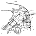
以下、上記エアクリーナの従来例を、チェンソーの後部及びそれに搭載された掃気口を左右に2つずつ計4つ有する反転掃気式の2サイクルガソリンエンジンの一部と共に示す図4を参照しながら説明する。 Hereinafter, a conventional example of the air cleaner will be described with reference to FIG. 4 which shows a rear portion of a chain saw and a part of a reverse scavenging two-stroke gasoline engine having a total of four scavenging ports mounted on the left and right. .
図示従来例のチェンソー50においては、本体ハウジング52の上面部及び後部にまたがって、スロットルロックレバーやスロットルトリガーが組み込まれたトップハンドル54が配設され、本体ハウジング52内にエンジン60により駆動される冷却ファン(図示せず)が配設され、この冷却ファンにより本体ハウジング52内に吸入された空気の一部を、前記トップハンドル54及び本体ハウジング52の後部に配設されたエアクリーナ10’及び気化器65を介してエンジン60のシリンダ62内に吸入させるようになっている。
In the illustrated chain saw 50, a
エンジン60は、本体ハウジング52内に、横置きで、その吸気口63を上側にしかつ頭部(燃焼室)64を機体後方に向けて搭載されており、前記吸気口63より上流側に合成ゴム材よりなる吸振性通気管66を介して前記気化器65が連結されるとともに、該気化器65の直上流にエアクリーナ10’が連接されている。
The
エアクリーナ10’は、底壁15[気化器65側(上側)の底壁15Aとクリーナ入口16側(下側)の底壁15B]及び外周側壁15Cを持つ合成樹脂製のケース11と、該ケース11の上面開口を覆うように被せられた厚板状のフィルタ(濾過エレメント)12と、該フィルタ12を前記ケース11との間に挟み込むように被せられた合成樹脂製のカバー13と、このカバー13を取着すべく、ケース11における気化器側底壁15Aとクリーナ入口側底壁15Bとの境目辺りに形成された雌ねじ部17にねじ込まれたねじ部材18と、を備え、前記ねじ部材18を弛めれば、カバー13及びフィルタ12を取り外すことができるようになっている。
The air cleaner 10 'is formed of a
また、前記エアクリーナ10’のケース11部分が図5に示されているように、ケース11の気化器側底壁15Aには、気化器65における内部通路67の吸入口67aに連なるようにクリーナ出口20が設けられている。クリーナ出口20は、その上端部(ボス部20a)が底壁15A上面より若干上側に突出せしめられている。底壁15A上には、気化器65から吹き返される混合燃料(後述する)をフィルタ12側に向かわせないようにするための板金製の吹き返し誘導部材19が配設されている。
Further, as shown in FIG. 5, the
この吹き返し誘導部材19は、図6に取付状態の平面図が示されているように、前記クリーナ出口20の中央上に跨る逆リップ溝形状の折曲板部19Aと該折曲板部19Aの上板部19aから雌ねじ部17側にやや下向きに折れ曲がって延設された三日月状板部19Bとからなり、折曲板部19Aの両側板部19b、19bの下端には、外側に折り曲がるねじ止め板部19c、19cが設けられている。止めねじ22が、ねじ止め板部19c、19cに設けられた通し穴19d及びケース11の底壁15Aに設けられたボス部29a付き挿通穴29、29を介して気化器65にねじ込まれて、吹き返し誘導部材19とケース11とが気化器65に共締め固定されている。
The blow-
また、ケース11のクリーナ入口側底壁15Bには、気化器65から吹き返された燃料を集めて溜める燃料溜部25を画成すべく、立上板部27、28が設けられている。
Further, rising
ところで、上記した如くのチェンソー50等におけるエンジン60の吸気系においては、何ら対策を講じなければ、吸気口63からの吹き返しにより、気化器65で一旦は霧化された混合燃料(ガソリンと潤滑用オイル)がクリーナ出口20を介してケース11内に吹き返される。この吹き返し流を、図5に破線矢印で示す。クリーナ出口20を介してケース11内に吹き返された混合燃料は、吹き返し誘導部材19に誘導されて(図4の破線矢印)、ケース11の内壁面(外周側壁15Cや底壁15)等を伝って前記燃料溜部25に集められて溜められるが、その一部はそのままフィルタ12に付着する。また、溜められた混合燃料の一部は吹き返し後の吸入時に吸気負圧によりクリーナ出口20側に吸引されて気化器65に還流されるが、その一部は燃料溜部25に残り、燃料溜部25から溢れ出るなどしてフィルタ12に付着する。
By the way, in the intake system of the
フィルタ12に付着した混合燃料は、ガソリンだけが気化し、オイル分のみがケース11及びフィルタ12に残り、その結果、フィルタ12の通気抵抗が増え(吸入空気量減少)、気化器65のノズルに掛かるブースト圧が増加し、燃料流量が増え、燃焼に供される混合気が過濃状態となり、出力が低下し、作業性が悪化するばかりか、作業者は頻繁にフィルタ12のメンテナンス(交換等)を強いられる。そのフィルタ12のメンテナンスを怠った場合、ケース11から飽和したオイルにより、機体が汚れるだけでなく、土壌汚染を引き起こす(刈払機等は、特に米処でそういった不具合が嫌がられる)。
In the mixed fuel adhering to the filter 12, only gasoline is vaporized, and only the oil remains in the
上記のように気化器から吹き返される混合燃料による不具合・トラブルを抑制ないし低減すべく、従来より、例えば特許文献1、2等に見られるように、気化器から吹き返された混合燃料を集めて溜める燃料溜部と、該燃料溜部に溜まる燃料を吸気負圧を利用して気化器側へ還流させるための戻し流路とを設けること等が提案されている。しかし、上記特許文献に所載のように、前記戻し流路を、エアクリーナの外側を通ってケースの燃料溜部と気化器とを連結する管路(パイプ)で構成すると、必然的に前記管路の長さが長くなって、燃料溜部に溜まった燃料が該燃料溜部から気化器側へ到達する時間が長くなる(遅くなる)可能性や、逆方向からの燃料混入等によって管路内にエアが溜まる(管路が詰まる)可能性があり、それだけでは、特に、機体(エンジン・エアクリーナ)の姿勢変化が大きくなりやすい(傾斜、転倒等をしやすい)チェンソーや刈払機等の携帯型作業機においては、前記不具合・トラブルを十分には解消できない。 In order to suppress or reduce problems and problems caused by the mixed fuel blown back from the vaporizer as described above, conventionally, the mixed fuel blown back from the vaporizer is collected and stored, as seen in, for example, Patent Documents 1 and 2. It has been proposed to provide a fuel reservoir and a return channel for refluxing the fuel stored in the fuel reservoir to the carburetor side using the intake negative pressure. However, as described in the above-mentioned patent documents, when the return flow path is constituted by a pipe (pipe) connecting the fuel reservoir of the case and the carburetor through the outside of the air cleaner, the pipe inevitably becomes the pipe The length of the passage is increased, and the time for the fuel accumulated in the fuel reservoir to reach the carburetor from the fuel reservoir may be prolonged (delayed), or the fuel may be mixed in the reverse direction, etc. There is a possibility that air may be accumulated inside (the pipe line may be clogged), and in particular, the posture change of the airframe (engine, air cleaner) is likely to be large (it is easy to tilt, fall, etc.) The mold working machine can not sufficiently solve the problems and problems.
上記のような問題に対し、例えば特許文献3には、前記戻し流路を、クリーナ出口を中心として放射状に複数個設けるとともに、その戻し流路を、クリーナ底壁に立設されたスロープ付き流路形成板部を含んで構成することが提案されているが、そのような従来技術においても、依然として、戻し流路を構成する流路形成板部の配置構成が難しいといった課題や、一旦燃料溜部に溜まってしまった燃料をクリーナ出口を介して気化器側へ効率よく還流させることができないといった課題があった。
In order to solve the above problems, for example, in
本発明は、上記事情に鑑みてなされたもので、その目的とするところは、簡単な構成でもって、気化器から吹き返される混合燃料に起因する不具合・トラブルを効果的に抑制ないし低減し得て、フィルタの長寿命化・メンテナンス頻度の低減等を図ることのできるエアクリーナを提供することにある。 The present invention has been made in view of the above circumstances, and the object of the present invention is to simply suppress or reduce problems and problems caused by the mixed fuel blown back from the vaporizer with a simple configuration. It is an object of the present invention to provide an air cleaner capable of prolonging the service life of the filter and reducing the frequency of maintenance.
前記の目的を達成すべく、本発明に係るエアクリーナは、基本的には、エンジンの吸気系における気化器の直上流に配設されるもので、前記気化器側に位置するクリーナ底壁に設けられたクリーナ出口の周りに形成され、前記気化器から吹き返された混合燃料を集めて溜めておく燃料溜部と、前記燃料溜部に溜まる混合燃料を表面張力および吸気負圧を利用して前記気化器側へ還流させるべく、一端側開口が前記燃料溜部に連通するとともに、他端側開口が前記クリーナ出口に連通するスリット状の戻し通路とを備えていることを特徴としている。 In order to achieve the above object, the air cleaner according to the present invention is basically disposed immediately upstream of the carburetor in the intake system of the engine, and provided on the cleaner bottom wall located on the carburetor side. The fuel reservoir formed around the cleaner outlet for collecting and storing the mixed fuel blown back from the carburetor, and the blended fuel accumulated in the fuel reservoir using the surface tension and the intake negative pressure One end side opening is communicated with the fuel reservoir and the other end side opening is provided with a slit-like return passage communicating with the cleaner outlet in order to return to the carburetor side.
好ましい態様では、前記戻し通路は、前記クリーナ底壁に並んで立設された板状リブの間に形成される。 In a preferred aspect, the return passage is formed between plate-like ribs erected in line with the cleaner bottom wall.
更に好ましい態様では、前記板状リブは、前記クリーナ底壁に一体成形される。 In a further preferred aspect, the plate-like rib is integrally formed on the cleaner bottom wall.
別の好ましい態様では、前記戻し通路を構成する複数の板状リブが平行に配置される。 In another preferred embodiment, a plurality of plate-like ribs constituting the return passage are arranged in parallel.
他の好ましい態様では、前記クリーナ出口を介して当該エアクリーナ内に吹き返された混合燃料をフィルタ側ではなく前記燃料溜部側に向かうように誘導する吹き返し誘導部材が、前記クリーナ出口および前記戻し通路を覆うように且つ前記クリーナ出口および前記戻し通路から所定の距離をあけて配設される。 In another preferred embodiment, a blow-back guide member for guiding the mixed fuel blown back into the air cleaner through the cleaner outlet not to the filter side but to the fuel reservoir side is the cleaner outlet and the return passage. It is arranged to cover and at a predetermined distance from the cleaner outlet and the return passage.
他の好ましい態様では、前記クリーナ出口を取り囲むように前記クリーナ底壁の外周に立設された外周側壁の内周に、前記外周側壁に付着した混合燃料を前記クリーナ底壁側に向かうように誘導する側壁流れ誘導部が設けられる。 In another preferred aspect, the mixed fuel adhering to the outer peripheral side wall is directed toward the cleaner lower wall side on the inner periphery of the outer peripheral side wall provided upright on the outer periphery of the cleaner bottom wall so as to surround the cleaner outlet. Side wall flow guides are provided.
更に好ましい態様では、前記クリーナ底壁に、一端が前記外周側壁に設けられた前記側壁流れ誘導部に連なるとともに、他端が前記クリーナ出口に連なる流路形成リブが立設される。 In a further preferred aspect, a channel forming rib is provided on the cleaner bottom wall, one end of which is connected to the side wall flow guiding portion provided on the outer peripheral side wall and the other end is connected to the cleaner outlet.
前記側壁流れ誘導部は、好ましくは、前記外周側壁の内周から内側へ向けて三角状に膨出した段差部分から構成されるとともに、前記外周側壁に付着した混合燃料の一部を前記流路形成リブに誘導すべく、前記クリーナ底壁に対して垂直に且つ前記流路形成リブに連なるように形成された上辺段部と、前記外周側壁に付着した混合燃料の他部を前記クリーナ底壁に誘導すべく、前記クリーナ底壁に対して傾斜して設けられた下辺段部とを含んで構成される。 Preferably, the side wall flow guiding portion is constituted by a stepped portion which bulges in a triangular shape from the inner periphery to the inner side of the outer peripheral side wall, and part of the mixed fuel attached to the outer peripheral side wall is the flow passage An upper side step formed perpendicular to the cleaner bottom wall and connected to the flow path forming rib so as to be guided to the forming rib, and the other portion of the mixed fuel attached to the outer peripheral side wall are the cleaner bottom wall And a lower side step portion provided to be inclined with respect to the cleaner bottom wall.
前記燃料溜部は、好ましくは、前記クリーナ底壁に相互に傾斜して交差するように立設された堰状板部を含んで構成される。 The fuel reservoir preferably includes ridged plate portions erected so as to intersect with each other on the bottom wall of the cleaner.
本発明に係るエアクリーナでは、気化器から吹き返された混合燃料を集めて溜める燃料溜部に加えて、一端側開口が燃料溜部に連通するとともに、他端側開口がクリーナ出口に連通するスリット状の戻し通路が設けられているので、燃料溜部に溜まる混合燃料は、その後、戻し通路の表面張力および吸気負圧により、前記スリット状の戻し通路を通じて効率よく気化器側に還流せしめられる。 In the air cleaner according to the present invention, in addition to the fuel reservoir for collecting and storing the mixed fuel blown back from the carburetor, the one end side opening communicates with the fuel reservoir and the other end side opening communicates with the cleaner outlet Since the return passage is provided, the mixed fuel accumulated in the fuel reservoir is then efficiently returned to the carburetor side through the slit-like return passage by the surface tension of the return passage and the intake negative pressure.
そのため、フィルタに付着する混合燃料量が従来例のものに比べて大幅に低減され、その結果、気化器から吹き返される混合燃料に起因する不具合・トラブルを効果的に抑制ないし低減し得て、フィルタの長寿命化・メンテナンス頻度の低減等を図ることができる。 Therefore, the amount of mixed fuel adhering to the filter is significantly reduced as compared to that of the conventional example, and as a result, it is possible to effectively suppress or reduce troubles and problems caused by the mixed fuel blown back from the carburetor. Long life and maintenance frequency can be reduced.
以下、本発明の実施形態を図面を参照しながら説明する。 Hereinafter, embodiments of the present invention will be described with reference to the drawings.
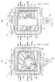
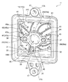
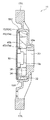
図1(A)は、本発明に係るエアクリーナの一実施形態のケース部分を示す平面図、図1(B)は、図1(A)に示されるケースに吹き返し誘導部材を取り付けた状態を示す平面図、図2は、図1(A)に示されるケースの斜視図、図3は、図1(B)のX−X矢視線に従う断面図である。 FIG. 1 (A) is a plan view showing a case portion of an embodiment of the air cleaner according to the present invention, and FIG. 1 (B) shows a state in which a blowback induction member is attached to the case shown in FIG. 1 (A). A plan view, FIG. 2 is a perspective view of the case shown in FIG. 1 (A), and FIG. 3 is a cross-sectional view taken along the line of arrows XX in FIG. 1 (B).
本実施形態のエアクリーナ10は、前述した図4、図5に示される従来例のエアクリーナ10’と基本構成、すなわち、ケース11、フィルタ12、カバー13、ねじ部材18、吹き返し誘導部材19等を備えている構成は同じであり、基本的に、ケース11の構成(および、それに伴う各部の構成)が異なるだけであるので、従来例のエアクリーナ10’の各部に対応する部分には共通の符号を付して重複説明を省略し、以下においては、相異点を重点的に説明する。
The
本実施形態のエアクリーナ10のケース11は、基本的に、略矩形平板状の底壁15及び当該底壁15の外周に立設された外周側壁15Cを有し、そのケース11において、気化器65から吹き返された混合燃料を集めて溜めるべく、前記底壁15における気化器側底壁(クリーナ底壁)15Aに設けられたクリーナ出口20の周り(例えば、通常の使用(作業)状態においてクリーナ出口20に対して下方の位置)に燃料溜部30が形成されている。また、本実施形態では、カバー13及びフィルタ12を着脱するためのねじ部材18がねじ込まれる雌ねじ部17が形成されたねじ取付部17Aは、前記外周側壁15Cの上下中央に延設されている。
The
前記燃料溜部30は、主として、気化器側底壁15Aと、気化器側底壁15Aとクリーナ入口側底壁15Bとの間を仕切るように底壁15上に逆へ字状に立設された2つの堰状板部31、32とから形成されている。2つの堰状板部31、32は、それぞれ一端側が気化器側底壁15Aの外周部分を形成する外周側壁15Cに連なり、他端側が相互に傾斜して交差しており、吹き返された混合燃料が気化器側底壁15Aからクリーナ入口側底壁15B側に流出しないように堰き止めるとともに、その混合燃料が堰状板部31、32の交差部分に集まって溜まる構成となっている。
The
また、前記ケース11においては、前記燃料溜部30に溜まる混合燃料を表面張力および吸気負圧を利用して気化器65側へ還流させるべく、一端側開口が燃料溜部30に連通するとともに、他端側開口がクリーナ出口20に連通するスリット状の戻し通路35が設けられている。
In the
前記戻し通路35は、気化器側底壁15Aに略平行に並んで立設された2つの板状リブ33、34の間に形成されており、その板状リブ33、34同士の間隔(言い換えれば、戻し通路35の通路幅)は、戻し通路35の一端側が開口する燃料溜部30に溜まる混合燃料を表面張力および吸気負圧によって戻し通路35内(板状リブ33、34同士の隙間)に吸上げ可能な間隔とされている。また、板状リブ33、34は、その高さが前記堰状板部31、32の高さより若干低くなっており、吹き返された混合燃料をフィルタ12側ではなく燃料溜部30側に向かうように誘導するための吹き返し誘導部材19は、前記板状リブ33、34の先端から所定の距離をあけて位置せしめられている。すなわち、本実施形態では、前記吹き返し誘導部材19が、前記クリーナ出口20および前記戻し通路35を覆うように且つ前記クリーナ出口20および前記戻し通路35から所定の距離をあけて配設されている(図3参照)。
The
なお、本実施形態では、吹き返し誘導部材19は、前記クリーナ出口20の口径より若干大きい幅の略矩形状に形成されている。
In the present embodiment, the blow-
また、前記ケース11においては、外周側壁15Cや気化器側底壁15Aに付着した混合燃料を吸気負圧を利用して気化器65側へ還流させるべく、一端が外周側壁15Cに連なるとともに、他端がクリーナ出口20に連なる、前記板状リブ33、34より若干高さの低い流路形成リブ41、42、43、44が前記気化器側底壁15Aに立設されている。各流路形成リブ41、42、43、44は、クリーナ出口20を中心として略放射状に形成されており、その高さはクリーナ出口20のボス部20aの高さと略同じとなっている。また、流路形成リブ41、42の一端は、(フィルタ12側から視て)外周側壁15Cの左側の内周に連なり、流路形成リブ43、44の一端は、外周側壁15Cの右側の内周に連なっている。
Further, in the
また、本実施形態では、堰状板部32(2つの堰状板部31、32のうち長い方の堰状板部)や気化器側底壁15Aに付着した混合燃料を吸気負圧を利用して気化器65側へ還流させるべく、一端が堰状板部32に連なるとともに、他端がクリーナ出口20に連なる、前記流路形成リブ41、42、43、44と略同じ高さの流路形成リブ45も前記気化器側底壁15Aに立設されている。
Further, in the present embodiment, the mixed fuel attached to the scallop plate portion 32 (the scallop plate portion of the longer one of the two
さらに、前記ケース11においては、外周側壁15Cに付着した混合燃料を気化器側底壁15A側に向かうように誘導すべく、外周側壁15Cの内周から内側へ向けて三角状に膨出した段差部分からなる側壁流れ誘導部46、47、48、49が設けられている。
Furthermore, in the
前記側壁流れ誘導部46、47、48、49は、それぞれ外周側壁15Cに付着した混合燃料の一部を気化器側底壁15Aに設けられた前記流路形成リブ41、42、43、44に誘導すべく、気化器側底壁15Aに対して垂直に且つ前記流路形成リブ41、42、43、44に連なるように形成された上辺段部46a、47a、48a、49aと、外周側壁15Cに付着した混合燃料の他部を気化器側底壁15Aに誘導すべく、気化器側底壁15Aに対して傾斜して且つ気化器側底壁15Aに連なるように形成された下辺段部46b、47b、48b、49bとを含んで構成されている。側壁流れ誘導部46は、外周側壁15Cの左側の内周において、側壁流れ誘導部47より上側(すなわち、流路形成リブ42の一端より上側)に配置され、側壁流れ誘導部48は、外周側壁15Cの右側の内周において、側壁流れ誘導部49より上側(すなわち、流路形成リブ44の一端より上側)に配置されている。
The side wall
なお、本実施形態の気化器側底壁15Aには、挿通穴29のボス部29aと外周側壁15Cとを結ぶように横方向に延びるリブ状仕切板部36、37や、クリーナ出口20のボス部20aと堰状板部32とを結ぶように縦方向に延びるリブ状仕切板部38も立設されており、前記側壁流れ誘導部46、47、48、49は、リブ状仕切板部36、37や堰状板部31、32より上側に形成されている。
In the vaporizer side
このような構成とされた本実施形態のエアクリーナ10においては、吸気口63からの吹き返しにより、気化器65で一旦は霧化された混合燃料(ガソリンと潤滑用オイル)が前記ケース11内に吹き返される。この吹き返し流を、図1(A)および図2に破線矢印で示す。吹き返された混合燃料は、吹き返し誘導部材19によってフィルタ12側ではなく燃料溜部30側に向かうように誘導されてそこに溜められる。特に、通常の使用(作業)姿勢では、燃料溜部30が下方に位置することになるため、吹き返された混合燃料は、その自重によっても燃料溜部30に集められて溜められる。燃料溜部30に溜められた混合燃料は、吹き返し後の吸入時に、吸気負圧によりスリット状の戻し通路35を通ってクリーナ出口20側に吸引される。この場合、前記燃料溜部30に溜められた混合燃料は、スリット状の戻し通路35の表面張力によって戻し通路35内に吸引(通常の使用姿勢では上側に向かって吸引)されやすく、クリーナ出口20に引き込まれると、残りの混合燃料も、戻し通路35内に向けて次々と吸引されて、クリーナ出口20を介して気化器65に還流される。この吹き返し後の流れを、図1(A)および図2に実線矢印で示す。
In the
また、吹き返された混合燃料のうち気化器側底壁15Aに付着した混合燃料は、吸入時の吸気負圧や重力等により、流路形成リブ41、42、43、44、45やリブ状仕切板部36、37、38等を介して(伝って)クリーナ出口20側に吸引されることになる。
In addition, the mixed fuel attached to the carburetor-
さらに、外周側壁15Cに付着した混合燃料は、吸入時の吸気負圧や重力等により、その一部が側壁流れ誘導部46、47、48、49の上辺段部46a、47a、48a、49aに接して気化器側底壁15A側(すなわち、流路形成リブ41、42、43、44)に導かれて前記と同様にクリーナ出口20側に吸引されるとともに、その他部(上辺段部46a、47a、48a、49aにより気化器側底壁15A側に導かれなかった混合燃料)は、吸入時の吸気負圧や表面張力等のより、側壁流れ誘導部46、47、48、49の下辺段部46b、47b、48b、49bを伝って気化器側底壁15A側に導かれる。この場合、側壁流れ誘導部46、48の下辺段部46b、48bを伝って気化器側底壁15A側に導かれた混合燃料は、その下側の側壁流れ誘導部47、49の上辺段部47a、49aおよびそれに連なる流路形成リブ42、44に接しやすくなり、その大部分が流路形成リブ42、44を介して(伝って)クリーナ出口20側に吸引されることになる。また、側壁流れ誘導部47、49の下辺段部47b、49bを伝って気化器側底壁15A側に導かれた混合燃料は、その下側のリブ状仕切板部36、37に接しやすくなり、その大部分がリブ状仕切板部36、37を介して(伝って)クリーナ出口20側に吸引されるとともに、リブ状仕切板部36、37を介してクリーナ出口20側に吸引されなかった混合燃料は、その下側の堰状板部31、32を伝って燃料溜部30に溜められ、前記のように、戻し通路35を介してクリーナ出口20側に吸引されることになる。この吹き返し後の流れを、図2に一点鎖線矢印で示す。
Further, the mixed fuel adhering to the outer
このように、本実施形態のエアクリーナ10においては、気化器65から吹き返された混合燃料を集めて溜める燃料溜部30に加えて、一端側開口が燃料溜部30に連通するとともに、他端側開口がクリーナ出口20に連通する、所定の通路幅を有するスリット状の戻し通路35が設けられているので、燃料溜部30に溜まる混合燃料は、戻し通路35の表面張力および吹き返し直後に生成される吸気負圧により、戻し通路35およびクリーナ出口20を介して効率よく気化器65側に還流せしめられる。
Thus, in the
そのため、フィルタ12に付着する混合燃料量が従来例のものに比べて大幅に低減され、その結果、気化器65から吹き返される混合燃料に起因する不具合・トラブルを抑制ないし低減し得て、フィルタ12の長寿命化・メンテナンス頻度の低減等を図ることができる。 Therefore, the amount of mixed fuel adhering to the filter 12 is significantly reduced as compared to that of the conventional example, and as a result, it is possible to suppress or reduce problems and troubles caused by the mixed fuel blown back from the carburetor 65. Long life and maintenance frequency can be reduced.
また、フィルタ12への燃料付着量が低減されることにより、燃費を向上させることができるとともに、有害物質排出量も減らすことができる。 In addition, by reducing the amount of fuel adhering to the filter 12, not only fuel efficiency can be improved, but also the harmful substance discharge amount can be reduced.
また、戻し通路35が、気化器側底壁15Aに平行に並んで立設された2つの板状リブ33、34の間に形成されるので、簡単な構成でもって当該戻し通路35を形成することもできる。
In addition, since the
また、吹き返し誘導部材19が、クリーナ出口20および戻し通路35を覆うように且つクリーナ出口20および戻し通路35から所定の距離をあけて配設されているので、前記吹き返し誘導部材19により還流効果が高められるとともに、戻し通路35の気化器側底壁15Aとは反対側は依然として開放しているため、戻し通路35に異物等が混入しても当該戻し通路35が詰まることはない。
Further, since the blow-
また、外周側壁15Cの内周に、その外周側壁15Cの内周から内側へ向けて膨出した段差部分からなる側壁流れ誘導部46、47、48、49が設けられるとともに、気化器側底壁15Aに、一端が側壁流れ誘導部46、47、48、49に連なるとともに、他端がクリーナ出口20に連なる流路形成リブ41、42、43、44が立設されているので、吹き返された混合燃料のうち外周側壁15Cや気化器側底壁15Aに付着した混合燃料も、吹き返し直後に生成される吸気負圧や重力等により、クリーナ出口20を介して効率よく気化器65側に還流せしめられる。
Further, on the inner periphery of the outer
なお、本実施形態では、燃料溜部30は2つの堰状板部31、32を含んで構成されているが、燃料溜部30の構成は、吹き返された混合燃料をクリーナ出口20周辺に溜めることができれば、その形状は限定されず、例えば、吹き返された混合燃料が気化器側底壁15Aからクリーナ入口側底壁15B側へ流れ出ないように、気化器側底壁15Aとクリーナ入口側底壁15Bとの間に単に段差を設けるだけでもよい。
In the present embodiment, the
また、吹き返し誘導部材19も上記実施形態のものに限定されず、エアクリーナ(ケース11)内に吹き返された混合燃料がフィルタ12側ではなく燃料溜部30側に向かうように誘導できれば、その形状・材質等は限定されず、また、合成樹脂製のケース11と一体に成形してもよい。
Further, the blow-
本実施形態では、戻し通路35は直線状かつ一定の通路幅を有しているが、燃料溜部30に溜まる混合燃料を吸上げられれば、例えば、曲線状としてもよいし、当該戻し通路35の通路幅(すなわち、板状リブ33、34の間隔)も一定でなくてもよい。
In the present embodiment, the
また、戻し通路35を構成する板状リブ33、34、流路形成リブ41〜45、側壁流れ誘導部46〜49等は合成樹脂製のケース11(の底壁15Aや外周側壁15C)と一体に成形されているが、別体に形成してもよいし、その材質等も限定されないことは勿論である。
Further, the plate-
さらに、本実施形態では、燃料溜部30および戻し通路35がそれぞれ一つだけ設けられているが、動力作業機(チェンソー、刈払機、エンジンカッター、ヘッジトリマー等)の使用姿勢等に応じて、燃料溜部および戻し通路を複数設けてもよいことは当然である。
Furthermore, in the present embodiment, only one
10 エアクリーナ
11 ケース
12 フィルタ
13 カバー
15 底壁(クリーナ底壁)
15A 気化器側底壁
15B クリーナ入口側底壁
15C 外周側壁
19 吹き返し誘導部材
20 クリーナ出口
30 燃料溜部
31、32 堰状板部
33、34 板状リブ
35 戻し通路
41、42、43、44、45 流路形成リブ
46、47、48、49 側壁流れ誘導部
10
15A carburetor side
Claims (9)
前記気化器側に位置するクリーナ底壁に設けられたクリーナ出口の周りに形成され、前記気化器から吹き返された混合燃料を集めて溜めておく燃料溜部と、前記燃料溜部に溜まる混合燃料を表面張力および吸気負圧を利用して前記気化器側へ還流させるべく、一端側開口が前記燃料溜部に連通するとともに、他端側開口が前記クリーナ出口に連通するスリット状の戻し通路とを備えていることを特徴とするエアクリーナ。 An air cleaner disposed immediately upstream of a carburetor in an engine intake system, the air cleaner comprising:
A fuel reservoir formed around a cleaner outlet provided on the cleaner bottom wall located on the side of the carburetor, for collecting and storing the mixed fuel blown back from the carburetor, and the blended fuel to be stored in the fuel reservoir And a slit-like return passage, one end side of which communicates with the fuel reservoir and the other end side of which communicates with the cleaner outlet, in order to return to the carburetor side using surface tension and intake negative pressure. An air cleaner characterized by comprising.
前記側壁流れ誘導部は、前記外周側壁に付着した混合燃料の一部を前記流路形成リブに誘導すべく、前記クリーナ底壁に対して垂直に且つ前記流路形成リブに連なるように形成された上辺段部と、前記外周側壁に付着した混合燃料の他部を前記クリーナ底壁に誘導すべく、前記クリーナ底壁に対して傾斜して設けられた下辺段部とを含んで構成されていることを特徴とする請求項7に記載のエアクリーナ。 The side wall flow guiding portion is constituted by a stepped portion which is expanded in a triangular shape from the inner periphery of the outer peripheral side wall toward the inside,
The side wall flow guiding portion is formed to be continuous with the flow path forming rib perpendicularly to the cleaner bottom wall so as to guide a part of the mixed fuel attached to the outer peripheral side wall to the flow path forming rib. An upper side step portion, and a lower side step portion provided obliquely to the cleaner bottom wall so as to guide the other portion of the mixed fuel attached to the outer peripheral side wall to the cleaner bottom wall; The air cleaner according to claim 7, characterized in that:
Priority Applications (1)
| Application Number | Priority Date | Filing Date | Title |
|---|---|---|---|
| JP2015235775A JP6541559B2 (en) | 2015-12-02 | 2015-12-02 | Air cleaner |
Applications Claiming Priority (1)
| Application Number | Priority Date | Filing Date | Title |
|---|---|---|---|
| JP2015235775A JP6541559B2 (en) | 2015-12-02 | 2015-12-02 | Air cleaner |
Publications (2)
| Publication Number | Publication Date |
|---|---|
| JP2017101606A JP2017101606A (en) | 2017-06-08 |
| JP6541559B2 true JP6541559B2 (en) | 2019-07-10 |
Family
ID=59018021
Family Applications (1)
| Application Number | Title | Priority Date | Filing Date |
|---|---|---|---|
| JP2015235775A Active JP6541559B2 (en) | 2015-12-02 | 2015-12-02 | Air cleaner |
Country Status (1)
| Country | Link |
|---|---|
| JP (1) | JP6541559B2 (en) |
Families Citing this family (2)
| Publication number | Priority date | Publication date | Assignee | Title |
|---|---|---|---|---|
| JP6754735B2 (en) * | 2017-07-12 | 2020-09-16 | 川崎重工業株式会社 | Blow-back fuel suction structure |
| CN116641813A (en) * | 2023-05-17 | 2023-08-25 | 浙江崴光工贸有限公司 | Reverse-spraying and back-sucking structure of two-stroke gasoline engine |
-
2015
- 2015-12-02 JP JP2015235775A patent/JP6541559B2/en active Active
Also Published As
| Publication number | Publication date |
|---|---|
| JP2017101606A (en) | 2017-06-08 |
Similar Documents
| Publication | Publication Date | Title |
|---|---|---|
| US7475681B2 (en) | Breather apparatus in combustion engine | |
| US11712649B2 (en) | Cyclonic air filter assembly for an engine | |
| US4813385A (en) | General-purpose internal combustion engine | |
| US20150136065A1 (en) | Lubrication system for four-stroke engine | |
| JP2006035923A (en) | Fuel tank equipment | |
| EP2058506B1 (en) | Engine air cleaner and device for mounting air cleaner on engine | |
| JP5685445B2 (en) | Air cleaner | |
| JP6541559B2 (en) | Air cleaner | |
| US6454823B2 (en) | Air filter housing having a deflection bowl | |
| GB2321672A (en) | Venting device with integrated oil separator for a crankcase of an internal combustion engine | |
| CN101865052B (en) | Air filter unit | |
| US9854746B2 (en) | Backpack power tool with a drive motor and a blower driven by the drive motor | |
| JP4419818B2 (en) | Internal combustion engine | |
| JP2007120482A (en) | Blowby gas circulation device | |
| JP6754735B2 (en) | Blow-back fuel suction structure | |
| CN220415538U (en) | Box body of general gasoline engine and general gasoline engine | |
| JP2005133668A (en) | Engine air cleaner | |
| JPS5913332Y2 (en) | Internal combustion engine intake system | |
| JP2004144010A (en) | 4-cycle internal combustion engine | |
| JPS6213713A (en) | Air cleaner for internal-combustion engine | |
| JP2007002742A (en) | Engine air cleaner | |
| JPH08165962A (en) | Dustproof device for engine air cleaner | |
| JPS6213715A (en) | Blow-by gas reflux device for internal-combustion engine |
Legal Events
| Date | Code | Title | Description |
|---|---|---|---|
| A621 | Written request for application examination |
Free format text: JAPANESE INTERMEDIATE CODE: A621 Effective date: 20180920 |
|
| A977 | Report on retrieval |
Free format text: JAPANESE INTERMEDIATE CODE: A971007 Effective date: 20190521 |
|
| TRDD | Decision of grant or rejection written | ||
| A01 | Written decision to grant a patent or to grant a registration (utility model) |
Free format text: JAPANESE INTERMEDIATE CODE: A01 Effective date: 20190604 |
|
| A61 | First payment of annual fees (during grant procedure) |
Free format text: JAPANESE INTERMEDIATE CODE: A61 Effective date: 20190611 |
|
| R150 | Certificate of patent or registration of utility model |
Ref document number: 6541559 Country of ref document: JP Free format text: JAPANESE INTERMEDIATE CODE: R150 |
|
| R250 | Receipt of annual fees |
Free format text: JAPANESE INTERMEDIATE CODE: R250 |
|
| R250 | Receipt of annual fees |
Free format text: JAPANESE INTERMEDIATE CODE: R250 |
|
| R250 | Receipt of annual fees |
Free format text: JAPANESE INTERMEDIATE CODE: R250 |
|
| R250 | Receipt of annual fees |
Free format text: JAPANESE INTERMEDIATE CODE: R250 |