EP2474732B1 - Air cleaner - Google Patents
Air cleaner Download PDFInfo
- Publication number
- EP2474732B1 EP2474732B1 EP12000031.0A EP12000031A EP2474732B1 EP 2474732 B1 EP2474732 B1 EP 2474732B1 EP 12000031 A EP12000031 A EP 12000031A EP 2474732 B1 EP2474732 B1 EP 2474732B1
- Authority
- EP
- European Patent Office
- Prior art keywords
- cleaner
- fuel
- carburetor
- air cleaner
- towards
- Prior art date
- Legal status (The legal status is an assumption and is not a legal conclusion. Google has not performed a legal analysis and makes no representation as to the accuracy of the status listed.)
- Active
Links
- 239000000446 fuel Substances 0.000 claims description 81
- 238000009825 accumulation Methods 0.000 claims description 37
- 238000011144 upstream manufacturing Methods 0.000 claims description 6
- 238000012423 maintenance Methods 0.000 description 8
- 230000007257 malfunction Effects 0.000 description 7
- 238000003780 insertion Methods 0.000 description 4
- 230000037431 insertion Effects 0.000 description 4
- 238000002485 combustion reaction Methods 0.000 description 3
- 239000000314 lubricant Substances 0.000 description 3
- 230000001105 regulatory effect Effects 0.000 description 3
- 229920003002 synthetic resin Polymers 0.000 description 3
- 239000000057 synthetic resin Substances 0.000 description 3
- 238000001816 cooling Methods 0.000 description 2
- 230000007423 decrease Effects 0.000 description 2
- 239000000463 material Substances 0.000 description 2
- 238000005192 partition Methods 0.000 description 2
- 240000007594 Oryza sativa Species 0.000 description 1
- 235000007164 Oryza sativa Nutrition 0.000 description 1
- 239000002250 absorbent Substances 0.000 description 1
- 238000004140 cleaning Methods 0.000 description 1
- 238000010586 diagram Methods 0.000 description 1
- 238000006073 displacement reaction Methods 0.000 description 1
- 239000000428 dust Substances 0.000 description 1
- 238000002474 experimental method Methods 0.000 description 1
- 238000001914 filtration Methods 0.000 description 1
- 239000002184 metal Substances 0.000 description 1
- 239000000203 mixture Substances 0.000 description 1
- 231100000614 poison Toxicity 0.000 description 1
- 235000009566 rice Nutrition 0.000 description 1
- 230000002000 scavenging effect Effects 0.000 description 1
- 238000003900 soil pollution Methods 0.000 description 1
- 229920003051 synthetic elastomer Polymers 0.000 description 1
- 239000005061 synthetic rubber Substances 0.000 description 1
- 239000003440 toxic substance Substances 0.000 description 1
Images


Classifications
-
- F—MECHANICAL ENGINEERING; LIGHTING; HEATING; WEAPONS; BLASTING
- F02—COMBUSTION ENGINES; HOT-GAS OR COMBUSTION-PRODUCT ENGINE PLANTS
- F02M—SUPPLYING COMBUSTION ENGINES IN GENERAL WITH COMBUSTIBLE MIXTURES OR CONSTITUENTS THEREOF
- F02M35/00—Combustion-air cleaners, air intakes, intake silencers, or induction systems specially adapted for, or arranged on, internal-combustion engines
- F02M35/02—Air cleaners
- F02M35/024—Air cleaners using filters, e.g. moistened
-
- F—MECHANICAL ENGINEERING; LIGHTING; HEATING; WEAPONS; BLASTING
- F02—COMBUSTION ENGINES; HOT-GAS OR COMBUSTION-PRODUCT ENGINE PLANTS
- F02M—SUPPLYING COMBUSTION ENGINES IN GENERAL WITH COMBUSTIBLE MIXTURES OR CONSTITUENTS THEREOF
- F02M35/00—Combustion-air cleaners, air intakes, intake silencers, or induction systems specially adapted for, or arranged on, internal-combustion engines
- F02M35/02—Air cleaners
- F02M35/04—Air cleaners specially arranged with respect to engine, to intake system or specially adapted to vehicle; Mounting thereon ; Combinations with other devices
-
- F—MECHANICAL ENGINEERING; LIGHTING; HEATING; WEAPONS; BLASTING
- F02—COMBUSTION ENGINES; HOT-GAS OR COMBUSTION-PRODUCT ENGINE PLANTS
- F02M—SUPPLYING COMBUSTION ENGINES IN GENERAL WITH COMBUSTIBLE MIXTURES OR CONSTITUENTS THEREOF
- F02M17/00—Carburettors having pertinent characteristics not provided for in, or of interest apart from, the apparatus of preceding main groups F02M1/00 - F02M15/00
- F02M17/34—Other carburettors combined or associated with other apparatus, e.g. air filters
-
- F—MECHANICAL ENGINEERING; LIGHTING; HEATING; WEAPONS; BLASTING
- F02—COMBUSTION ENGINES; HOT-GAS OR COMBUSTION-PRODUCT ENGINE PLANTS
- F02M—SUPPLYING COMBUSTION ENGINES IN GENERAL WITH COMBUSTIBLE MIXTURES OR CONSTITUENTS THEREOF
- F02M35/00—Combustion-air cleaners, air intakes, intake silencers, or induction systems specially adapted for, or arranged on, internal-combustion engines
- F02M35/10—Air intakes; Induction systems
- F02M35/1015—Air intakes; Induction systems characterised by the engine type
- F02M35/1017—Small engines, e.g. for handheld tools, or model engines; Single cylinder engines
-
- F—MECHANICAL ENGINEERING; LIGHTING; HEATING; WEAPONS; BLASTING
- F02—COMBUSTION ENGINES; HOT-GAS OR COMBUSTION-PRODUCT ENGINE PLANTS
- F02M—SUPPLYING COMBUSTION ENGINES IN GENERAL WITH COMBUSTIBLE MIXTURES OR CONSTITUENTS THEREOF
- F02M35/00—Combustion-air cleaners, air intakes, intake silencers, or induction systems specially adapted for, or arranged on, internal-combustion engines
- F02M35/10—Air intakes; Induction systems
- F02M35/1015—Air intakes; Induction systems characterised by the engine type
- F02M35/10196—Carburetted engines
Definitions
- the present invention relates to an air cleaner disposed immediately upstream of a carburetor in an intake system of an engine, and, more particularly, to an air cleaner adapted to suppress or reduce malfunctions and problems caused by mixed fuel (gasoline and lubricant oil) that back flows from the carburetor.
- a two-stroke gasoline engine e.g., an approximately 25-100 cc small air-cooled internal combustion engine
- a carburetor as a fuel supplying and regulating means is provided in the intake system of such an engine, while an air cleaner for cleaning outside-air that is brought in by removing dust therefrom is disposed immediately upstream of this carburetor.
- FIG. 3 A conventional example of such an air cleaner is described below with reference to Fig. 3 where the rear portion of a chain saw is shown along with a portion of a two-stroke gasoline engine mounted thereon, the two-stroke gasoline engine being of a reverse-scavenging system having a total of four scavenging ports with two each on the left and right.
- a lateral L-shaped top handle 54 into which a throttle lock lever and a throttle trigger are incorporated, is so disposed as to span the upper surface part and rear part of a main housing 52.
- a cooling fan (not shown) driven by an engine 60 is disposed inside the main housing 52. A portion of the air brought into the main housing 52 by this cooling fan is brought into a cylinder 62 of the engine 60 via an air cleaner 10' and carburetor 65 disposed at the rear part of the top handle 54 and main housing 52.
- the engine 60 is mounted sideways within the main housing 52 with its intake port 63 on the upper side and its head part (combustion chamber) 64 facing rearward.
- the carburetor 65 is connected further upstream than the intake port 63 via a vibration-absorbent air pipe 66 comprising a synthetic rubber material, and the air cleaner 10' is connected immediately upstream of the carburetor 65.
- the air cleaner 10' comprises: a synthetic resin case 11 comprising a bottom wall 15 with a substantially inverted-V-shaped cross-section [a bottom wall 15A on the side of the carburetor 65 (upper side) and a bottom wall 15B on the side of a cleaner inlet 16 (lower side)] and a perimeter side-wall 15C; a thick plate-shaped filter (filtering element) 12 that is so disposed as to cover the upper opening of the case 11; a synthetic resin cover 13 that is disposed in such a manner as to be sandwiched the filter 12 between the case 11 and the cover 13;and a screw member 18 that is screwed into an internal thread part 17 formed around a boundary between the carburetor-side bottom wall 15A of the case 11 and the cleaner inlet-side bottom wall 15B in order to attach this cover 13, wherein the cover 13 and the filter 12 may be removed by loosening the screw member 18.
- the internal thread part 17 has its upper part (a boss part 17a) protrude upward from the bottom wall 15 (15A
- a cleaner outlet 20 is so provided in the carburetor-side bottom wall 15A of the case 11 as to be continuous with an intake port 67a of an internal passage 67 in the carburetor 65.
- An upper end part (a boss part 20a) of the cleaner outlet 20 protrudes slightly upward from the upper surface of the bottom wall 15A.
- a back flow guide member 19 made of a metal plate and for preventing mixed fuel (discussed later) that back flows from the carburetor 65 from traveling towards the filter 12.
- this guide member 19 comprises: a bent plate part 19A of an inverted lip groove shape that lies above the center of the cleaner outlet 20; and a crescent-shaped plate part 19B that extends from an upper plate part 19a of the bent plate part 19A in such a manner as to bend slightly downward towards the internal thread part 17. Screwing plate parts 19c, 19c that bend outward are respectively provided at the lower ends of both side plate parts 19b, 19b of the bent plate part 19A.
- upright plate parts 27, 28 are provided on the cleaner inlet-side bottom wall 15B of the case 11.
- the filter 12 Of the mixed fuel that adheres to the filter 12, only the gasoline evaporates, and the oil part alone remains at the case 11 and the filter 12. Consequently, the airflow resistance of the filter 12 increases (intake air amount decreases), the boost pressure exerted on the nozzle of the carburetor 65 increases, fuel flow increases, and the air-fuel mixture for combustion becomes excessively concentrated. Thus, not only does output decrease and performance worsen, but the filter 12 will also require frequent maintenance (replacement, etc.) by the operator. By way of example, with the engine mentioned above (27 cc engine displacement), the filter 12 will require maintenance approximately every 20 hours of use.
- the present invention is made in view of the circumstances above, and an object thereof is to provide an air cleaner that is capable of suppressing or reducing malfunctions and problems caused by mixed fuel that back flows from the carburetor, thereby prolonging filter life, reducing filter maintenance frequency, etc.
- an air cleaner is, fundamentally, one that is disposed immediately upstream of a carburetor in an intake system of an engine, the air cleaner comprising: a fuel accumulation part that is formed near a cleaner outlet provided in a cleaner bottom wall located towards the carburetor, the fuel accumulation part being adapted to collect and accumulate mixed fuel that back flows from the carburetor; a back flow guide member that guides the mixed fuel that back flows into the air cleaner via the cleaner outlet not towards a filter but towards the fuel accumulation part; and a plurality of return flow paths, each of which comprises one end that is in communication with the fuel accumulation part and another end that is in communication with the cleaner outlet so as to return the mixed fuel that accumulates in the fuel accumulation part back towards the carburetor utilizing intake negative pressure, wherein the plurality of return flow paths are formed in a radial fashion about the cleaner outlet.
- the fuel accumulation part comprise a weir-like plate part erected on the cleaner bottom wall.
- the plurality of return flow paths each comprise a flow path forming plate part that is erected on the cleaner bottom wall and whose upper end surface comprises a sloped surface that slopes downward towards the cleaner outlet.
- an air cleaner in addition to a fuel accumulation part that collects and accumulates mixed fuel that back flows from a carburetor, there is formed, in a radial fashion about a cleaner outlet, a plurality of return flow paths, each of which comprises one end that is in communication with the fuel accumulation part and another end that is in communication with the cleaner outlet.
- the mixed fuel that accumulates in the fuel accumulation part is thereafter efficiently returned towards the carburetor by means of intake negative pressure via the plurality of return flow paths formed in a radial fashion.
- the amount of mixed fuel that adheres to the filter is greatly reduced as compared to a conventional air cleaner. Consequently, it is possible to effectively suppress or reduce malfunctions and problems caused by mixed fuel that back flows from the carburetor, thereby prolonging filter life, reducing filter maintenance frequency, etc.
- the return flow paths each comprise a flow path forming plate part that is erected on the cleaner bottom wall
- the return flow paths consequently also serve as flow regulating plates that regulate the flow of the intake air, thereby reducing the amount of fuel that adheres to the filter without causing a drop in output, and so forth.
- the return flow paths are formed in a radial fashion, it is possible to reliably return the back flow mixed fuel to the carburetor regardless of the attitude of the equipment (i.e., engine, air cleaner) (e.g., even if it is significantly tilted, or turned over).
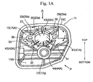
- Fig. 1A is a plan view showing the case portion of one embodiment of an air cleaner according to the present invention.
- Fig. 1B is a plan view showing a state where a back flow guide member is attached to the case shown in Fig. 1A .
- Fig. 2A is a perspective view of Fig. 1A as viewed in the P-direction.
- Fig. 2B is a perspective view of Fig. 1A as viewed in the R-direction.
- An air cleaner 10 of the present embodiment is similar to the air cleaner 10' in the conventional example shown in Fig. 3 and Fig. 4 discussed above in terms of its basic structure, that is, it comprises the case 11, the filter 12, the cover13, the screw member 18, the guide member 19, etc. It only differs in terms of the structure(s) on the bottom wall 15 of the case 11. As such, parts that correspond to the parts of the air cleaner 10' in the conventional example are designated with like reference numerals while omitting duplicate descriptions therefor. The description below is provided mainly with respect to points where the two differ.
- a fuel accumulation part 30 is formed near, and so as to surround, the cleaner outlet 20 provided in the carburetor-side bottom wall 15A.
- the fuel accumulation part 30 is formed mainly of the carburetor-side bottom wall 15A, the perimeter side-wall 15C that forms a perimeter portion thereof, and two weir-like plate parts 31, 32 that are erected on the bottom wall 15 so as to separate the carburetor-side bottom wall 15A and the cleaner inlet-side bottom wall 15B and in the shape of a V that is turned sideways and symmetrical about a horizontal line.
- Each of the weir-like plate parts 31, 32 is such that one end is continuous with the perimeter side-wall 15C while the other end is continuous with the boss part 17a of the internal thread part 17, and is thus configured to stem the back flow mixed fuel so that it does not flow out from the bottom wall 15A towards the bottom wall 15B.
- rib-like partition plate parts 36, 37, 38 are also erected in such a manner as to connect parts near the boss parts 29a of the insertion holes 29, 29 with the perimeter side-wall 15C, the insertion holes 29, 29 being for securing the guide member 19 with screws.
- the height of each of the rib-like partition plate parts 36, 37, 38 is approximately the same as the heights of the boss part 20a of the cleaner outlet 20 and of the boss parts 29a of the insertion holes 29, 29.
- the fuel accumulation part 30 is provided with return flow paths 41, 42, 43, 44, each of which comprises one end that is in communication with the cleaner outlet 20 and another end that is in communication with the fuel accumulation part 30.
- the return flow paths 41, 42, 43, 44 respectively comprise flow path forming plate parts 41A, 42A, 43A, 44A that are erected in a radial fashion about the cleaner outlet 20 and whose respective upper end surfaces each comprise a flat (not curved) sloped surface that slopes downward towards the cleaner outlet 20.
- Each of the flow path forming plate parts 41A, 42A, 43A, 44A has one end that is continuous with the cleaner outlet 20, and its sloped surface is located at a higher position than the boss part 20a of the cleaner outlet 20.
- the other end of the flow path forming plate part 41A is continuous with the weir-like plate part 31.
- the other end of the flow path forming plate part 42A is continuous with the weir-like plate part 32.
- the other end of the flow path forming plate part 43A is continuous with the perimeter side-wall 15C.
- the other end of the flow path forming plate part 44A is continuous with the boss part 17a of the internal thread part 17.
- the mixed fuel gasoline and lubricant oil
- This back flow is represented with broken line arrows in Fig. 1A .
- the back flow mixed fuel is guided by the guide member 19 not towards the filter 12 but towards the fuel accumulation part 30 and is accumulated therein, while a portion thereof hits the perimeter wall of the fuel accumulation part 30 (i.e., the perimeter side-wall 15C and the weir-like plate parts 31, 32) and is bounced back.
- the mixed fuel that is accumulated in the fuel accumulation part 30 is sucked towards the cleaner outlet 20 upon intake following the back flow due to the intake negative pressure.
- the plurality of return flow paths 41, 42, 43, 44 respectively comprising the flow path forming plate parts 41A, 42A, 43A, 44A with the slopes, are formed in a radial fashion about the cleaner outlet 20. Consequently, the mixed fuel that accumulates in the fuel accumulation part 30 is returned towards the carburetor 65 efficiently via the cleaner outlet 20 by means of the intake negative pressure generated immediately after back flow.
- the amount of mixed fuel that adheres to the filter 12 is reduced significantly as compared to the conventional example.
- the filter 12 required maintenance approximately every 20 hours of use in the conventional example, it has been confirmed through experiments that with the air cleaner 10 of the present embodiment, the filter 12 does not require maintenance for up to approximately five times as long (i.e., 100 hours).
- the return flow paths 41, 42, 43, 44 respectively comprise the flow path forming plate parts 41A, 42A, 43A, 44A erected on the cleaner bottom wall 15A in a radial fashion
- the flow path forming plate parts 41 A, 42A, 43A, 44A also serve as flow regulating plates that regulate the flow of intake air. Consequently, the amount of fuel that adheres to the filter 12 may be reduced without causing output to drop, among other things.
- the mixed fuel that has back flowed may be returned to the carburetor reliably regardless of what attitude the equipment (i.e., engine, air cleaner) may be placed in (e.g., even if it is tilted significantly, or turned over).
- the fuel accumulation part 30 comprises the two weir-like plate parts 31, 32.
- the structure of the fuel accumulation part 30 is by no means limited to any particular shape so long as it is capable of accumulating the back flow mixed fuel near the cleaner outlet 20.
- a level difference may simply be provided between the bottom wall 15A and the bottom wall 15B so as to prevent the back flow mixed fuel from flowing out towards the bottom wall 15B from the bottom wall 15A.
- the back flow guide member is also not limited to that of the embodiment above, and its shape, material, etc., are not limited in any particular way so long as they allow the guiding of the mixed fuel that has back flowed into the air cleaner (case 11) not towards the filter 12 but towards the fuel accumulation part 30.
- it may also be molded integrally with the synthetic resin case 11.
Description
- The present invention relates to an air cleaner disposed immediately upstream of a carburetor in an intake system of an engine, and, more particularly, to an air cleaner adapted to suppress or reduce malfunctions and problems caused by mixed fuel (gasoline and lubricant oil) that back flows from the carburetor.
- By way of example, with respect to such portable power working machine as chain saws, brush cutters, etc., a two-stroke gasoline engine, e.g., an approximately 25-100 cc small air-cooled internal combustion engine, is ordinarily provided within the main housing as a power source for driving the operating part, e.g., the saw chain, etc. Further, a carburetor as a fuel supplying and regulating means is provided in the intake system of such an engine, while an air cleaner for cleaning outside-air that is brought in by removing dust therefrom is disposed immediately upstream of this carburetor.
- A conventional example of such an air cleaner is described below with reference to
Fig. 3 where the rear portion of a chain saw is shown along with a portion of a two-stroke gasoline engine mounted thereon, the two-stroke gasoline engine being of a reverse-scavenging system having a total of four scavenging ports with two each on the left and right. - With respect to
chain saw 50 shown in the diagram, a lateral L-shaped top handle 54, into which a throttle lock lever and a throttle trigger are incorporated, is so disposed as to span the upper surface part and rear part of amain housing 52. A cooling fan (not shown) driven by anengine 60 is disposed inside themain housing 52. A portion of the air brought into themain housing 52 by this cooling fan is brought into acylinder 62 of theengine 60 via an air cleaner 10' andcarburetor 65 disposed at the rear part of thetop handle 54 andmain housing 52. - The
engine 60 is mounted sideways within themain housing 52 with itsintake port 63 on the upper side and its head part (combustion chamber) 64 facing rearward. Thecarburetor 65 is connected further upstream than theintake port 63 via a vibration-absorbent air pipe 66 comprising a synthetic rubber material, and the air cleaner 10' is connected immediately upstream of thecarburetor 65. - The air cleaner 10' comprises: a
synthetic resin case 11 comprising abottom wall 15 with a substantially inverted-V-shaped cross-section [abottom wall 15A on the side of the carburetor 65 (upper side) and abottom wall 15B on the side of a cleaner inlet 16 (lower side)] and a perimeter side-wall 15C; a thick plate-shaped filter (filtering element) 12 that is so disposed as to cover the upper opening of thecase 11; asynthetic resin cover 13 that is disposed in such a manner as to be sandwiched thefilter 12 between thecase 11 and thecover 13;and ascrew member 18 that is screwed into aninternal thread part 17 formed around a boundary between the carburetor-side bottom wall 15A of thecase 11 and the cleaner inlet-side bottom wall 15B in order to attach thiscover 13, wherein thecover 13 and thefilter 12 may be removed by loosening thescrew member 18. It is noted that theinternal thread part 17 has its upper part (aboss part 17a) protrude upward from the bottom wall 15 (15A, 15B). - In addition, as can be seen in the
case 11 portion of the air cleaner 10' shown inFig. 4 , acleaner outlet 20 is so provided in the carburetor-side bottom wall 15A of thecase 11 as to be continuous with anintake port 67a of aninternal passage 67 in thecarburetor 65. An upper end part (aboss part 20a) of thecleaner outlet 20 protrudes slightly upward from the upper surface of thebottom wall 15A. On thebottom wall 15A is disposed a backflow guide member 19 made of a metal plate and for preventing mixed fuel (discussed later) that back flows from thecarburetor 65 from traveling towards thefilter 12. - As can be seen in the plan view in
Fig. 5A showing an attached state and the perspective view inFig. 5B , thisguide member 19 comprises: abent plate part 19A of an inverted lip groove shape that lies above the center of thecleaner outlet 20; and a crescent-shaped plate part 19B that extends from anupper plate part 19a of thebent plate part 19A in such a manner as to bend slightly downward towards theinternal thread part 17. Screwingplate parts side plate parts bent plate part 19A. Setscrews 22 are screwed into thecarburetor 65 via through-holes 19d respectively provided in thescrewing plate parts insertion holes boss part 29a that are provided in thebottom wall 15A of thecase 11. The backflow guide member 19 and thecase 11 are thus fastened together and affixed to thecarburetor 65. - In addition, in order to define a
fuel accumulation part 25 for collecting and accumulating fuel that back flows from thecarburetor 65,upright plate parts side bottom wall 15B of thecase 11. - However, with respect to the intake system of the
engine 60 described above, unless some countermeasure is taken, mixed fuel (gasoline and lubricant oil) that has been atomized at thecarburetor 65 back flows into thecase 11 via thecleaner outlet 20 due to back flow from theintake port 63. This back flow is represented with broken line arrows inFig. 4 . The mixed fuel that has back flowed into thecase 11 via thecleaner outlet 20 is guided by the back flow guide member 19 (as shown by the broken line arrows inFig. 3 ), and is collected and accumulated in thefuel accumulation part 25 via the inner wall surfaces (i.e., the perimeter side-wall 15C, the bottom wall 15) of thecase 11, etc., while a portion thereof simply adheres to thefilter 12. In addition, although a portion of the accumulated mixed fuel is returned to thecarburetor 65 by being sucked towards thecleaner outlet 20 due to the intake negative pressure at the time of intake following the back flow, a portion thereof remains in thefuel accumulation part 25 and adheres to thefilter 12 as it overflows from thefuel accumulation part 25, for example. - Of the mixed fuel that adheres to the
filter 12, only the gasoline evaporates, and the oil part alone remains at thecase 11 and thefilter 12. Consequently, the airflow resistance of thefilter 12 increases (intake air amount decreases), the boost pressure exerted on the nozzle of thecarburetor 65 increases, fuel flow increases, and the air-fuel mixture for combustion becomes excessively concentrated. Thus, not only does output decrease and performance worsen, but thefilter 12 will also require frequent maintenance (replacement, etc.) by the operator. By way of example, with the engine mentioned above (27 cc engine displacement), thefilter 12 will require maintenance approximately every 20 hours of use. If such maintenance is neglected, not only will the device body become dirty due to the oil that overflows from thecase 11, but soil pollution may also be caused (such malfunctions in lawn mowers, etc., are viewed unfavorably particularly in regions where rice is produced in large amounts). - As can be seen in, by way of example,
JP Utility Model Publication (Kokoku) No. 38-21007 Y (1963 JP Utility Model Application Publication (Kokai) No. 63-75559 U (1988 US 2001/0025471 A1 , etc., providing a fuel accumulation part that collects and accumulates mixed fuel that back flows from the carburetor, and a return flow path for returning the fuel accumulated in the fuel accumulation part back towards the carburetor utilizing intake negative pressure has already been proposed among other things in order to suppress or reduce malfunctions and problems caused by mixed fuel that back flows from the carburetor as discussed above. However, the above on its own cannot sufficiently address the above-mentioned malfunctions and problems, particularly with respect to such portable power equipment as chain saws, lawn mowers, etc., where the attitude of the device body (i.e., engine, air cleaner) tends to vary significantly (e.g., tends to be tilted, turned over, etc.). - The present invention is made in view of the circumstances above, and an object thereof is to provide an air cleaner that is capable of suppressing or reducing malfunctions and problems caused by mixed fuel that back flows from the carburetor, thereby prolonging filter life, reducing filter maintenance frequency, etc.
- In order to achieve the object above, an air cleaner according to an embodiment of the present invention is, fundamentally, one that is disposed immediately upstream of a carburetor in an intake system of an engine, the air cleaner comprising: a fuel accumulation part that is formed near a cleaner outlet provided in a cleaner bottom wall located towards the carburetor, the fuel accumulation part being adapted to collect and accumulate mixed fuel that back flows from the carburetor; a back flow guide member that guides the mixed fuel that back flows into the air cleaner via the cleaner outlet not towards a filter but towards the fuel accumulation part; and a plurality of return flow paths, each of which comprises one end that is in communication with the fuel accumulation part and another end that is in communication with the cleaner outlet so as to return the mixed fuel that accumulates in the fuel accumulation part back towards the carburetor utilizing intake negative pressure, wherein the plurality of return flow paths are formed in a radial fashion about the cleaner outlet.
- It is preferable that the fuel accumulation part comprise a weir-like plate part erected on the cleaner bottom wall.
- It is preferable that the plurality of return flow paths each comprise a flow path forming plate part that is erected on the cleaner bottom wall and whose upper end surface comprises a sloped surface that slopes downward towards the cleaner outlet.
- With an air cleaner according to an embodiment of the present invention, in addition to a fuel accumulation part that collects and accumulates mixed fuel that back flows from a carburetor, there is formed, in a radial fashion about a cleaner outlet, a plurality of return flow paths, each of which comprises one end that is in communication with the fuel accumulation part and another end that is in communication with the cleaner outlet. As a result, the mixed fuel that accumulates in the fuel accumulation part is thereafter efficiently returned towards the carburetor by means of intake negative pressure via the plurality of return flow paths formed in a radial fashion.
- Thus, the amount of mixed fuel that adheres to the filter is greatly reduced as compared to a conventional air cleaner. Consequently, it is possible to effectively suppress or reduce malfunctions and problems caused by mixed fuel that back flows from the carburetor, thereby prolonging filter life, reducing filter maintenance frequency, etc.
- In addition, as the return flow paths each comprise a flow path forming plate part that is erected on the cleaner bottom wall, the return flow paths consequently also serve as flow regulating plates that regulate the flow of the intake air, thereby reducing the amount of fuel that adheres to the filter without causing a drop in output, and so forth.
- In addition, since the return flow paths are formed in a radial fashion, it is possible to reliably return the back flow mixed fuel to the carburetor regardless of the attitude of the equipment (i.e., engine, air cleaner) (e.g., even if it is significantly tilted, or turned over).
-
-
Fig. 1A is a plan view showing the case portion of an embodiment of an air cleaner according to the present invention.Fig. 1B is a plan view showing a state where a back flow guide member is attached to the case shown inFig. 1A . -
Fig. 2A is a perspective view ofFig. 1A as viewed in the P-direction.Fig. 2B is a perspective view ofFig. 1A as viewed in the R-direction. -
Fig. 3 is a sectional view showing a conventional example of an air cleaner along with the rear portion of a chain saw and a portion of a two-stroke gasoline engine mounted thereon. -
Fig. 4 is a plan view showing the case portion of the conventional air cleaner shown inFig. 3 . -
Figs. 5A and 5B show the back flow guide member used in the conventional air cleaner shown inFig. 3 , whereFig. 5A is a plan view of an attached state, andFig. 5B is a perspective view. - Embodiments of the present invention are described below with reference to the drawings.
-
Fig. 1A is a plan view showing the case portion of one embodiment of an air cleaner according to the present invention.Fig. 1B is a plan view showing a state where a back flow guide member is attached to the case shown inFig. 1A .Fig. 2A is a perspective view ofFig. 1A as viewed in the P-direction.Fig. 2B is a perspective view ofFig. 1A as viewed in the R-direction. - An
air cleaner 10 of the present embodiment is similar to the air cleaner 10' in the conventional example shown inFig. 3 andFig. 4 discussed above in terms of its basic structure, that is, it comprises thecase 11, thefilter 12, the cover13, thescrew member 18, theguide member 19, etc. It only differs in terms of the structure(s) on thebottom wall 15 of thecase 11. As such, parts that correspond to the parts of the air cleaner 10' in the conventional example are designated with like reference numerals while omitting duplicate descriptions therefor. The description below is provided mainly with respect to points where the two differ. - With respect to the
case 11 of theair cleaner 10 of the present embodiment, in order to collect and accumulate mixed fuel that back flows from thecarburetor 65, afuel accumulation part 30 is formed near, and so as to surround, thecleaner outlet 20 provided in the carburetor-side bottom wall 15A. Thefuel accumulation part 30 is formed mainly of the carburetor-side bottom wall 15A, the perimeter side-wall 15C that forms a perimeter portion thereof, and two weir-like plate parts bottom wall 15 so as to separate the carburetor-side bottom wall 15A and the cleaner inlet-side bottom wall 15B and in the shape of a V that is turned sideways and symmetrical about a horizontal line. Each of the weir-like plate parts wall 15C while the other end is continuous with theboss part 17a of theinternal thread part 17, and is thus configured to stem the back flow mixed fuel so that it does not flow out from thebottom wall 15A towards thebottom wall 15B. It is noted that, in thefuel accumulation part 30, rib-likepartition plate parts boss parts 29a of the insertion holes 29, 29 with the perimeter side-wall 15C, the insertion holes 29, 29 being for securing theguide member 19 with screws. The height of each of the rib-likepartition plate parts boss part 20a of thecleaner outlet 20 and of theboss parts 29a of the insertion holes 29, 29. - In addition, in order to return the fuel that accumulates in the
fuel accumulation part 30 back towards thecarburetor 65 utilizing intake negative pressure, thefuel accumulation part 30 is provided withreturn flow paths cleaner outlet 20 and another end that is in communication with thefuel accumulation part 30. - The
return flow paths plate parts cleaner outlet 20 and whose respective upper end surfaces each comprise a flat (not curved) sloped surface that slopes downward towards thecleaner outlet 20. Each of the flow path formingplate parts cleaner outlet 20, and its sloped surface is located at a higher position than theboss part 20a of thecleaner outlet 20. The other end of the flow path formingplate part 41A is continuous with the weir-like plate part 31. The other end of the flow path formingplate part 42A is continuous with the weir-like plate part 32. The other end of the flow path formingplate part 43A is continuous with the perimeter side-wall 15C. The other end of the flow path formingplate part 44A is continuous with theboss part 17a of theinternal thread part 17. - With respect to the
air cleaner 10 of the present embodiment thus configured, due to the back flow from theintake port 63, the mixed fuel (gasoline and lubricant oil) that has been atomized at thecarburetor 65 back flows into thecase 11. This back flow is represented with broken line arrows inFig. 1A . The back flow mixed fuel is guided by theguide member 19 not towards thefilter 12 but towards thefuel accumulation part 30 and is accumulated therein, while a portion thereof hits the perimeter wall of the fuel accumulation part 30 (i.e., the perimeter side-wall 15C and the weir-like plate parts 31, 32) and is bounced back. The mixed fuel that is accumulated in thefuel accumulation part 30 is sucked towards thecleaner outlet 20 upon intake following the back flow due to the intake negative pressure. In this case, of the mixed fuel that is accumulated in thefuel accumulation part 30, the portions that are in contact with the flow path formingplate parts cleaner outlet 20 and which form thereturn flow paths cleaner outlet 20 first. Since their flow speed becomes faster as they are drawn in, other portions of the mixed fuel are, one after another, also pulled towards the flow path formingplate parts carburetor 65 via thecleaner outlet 20. This flow that follows back flow is represented with solid line arrows inFig. 1A . - Thus, with respect to the
air cleaner 10 of the present embodiment, in addition to thefuel accumulation part 30 that accumulates mixed fuel that back flows from thecarburetor 65, the plurality ofreturn flow paths plate parts cleaner outlet 20. Consequently, the mixed fuel that accumulates in thefuel accumulation part 30 is returned towards thecarburetor 65 efficiently via thecleaner outlet 20 by means of the intake negative pressure generated immediately after back flow. - Thus, the amount of mixed fuel that adheres to the
filter 12 is reduced significantly as compared to the conventional example. As a result, it is possible to suppress or reduce malfunctions and problems caused by mixed fuel that back flows from the carburetor, thereby prolonging filter life, reducing filter maintenance frequency, etc. It is noted that whereas thefilter 12 required maintenance approximately every 20 hours of use in the conventional example, it has been confirmed through experiments that with theair cleaner 10 of the present embodiment, thefilter 12 does not require maintenance for up to approximately five times as long (i.e., 100 hours). - In addition, by virtue of the fact that the amount of adhesion to the
filter 12 is reduced, fuel efficiency may be improved and the emission of toxic substances reduced. - Further, since the
return flow paths plate parts cleaner bottom wall 15A in a radial fashion, the flow path formingplate parts filter 12 may be reduced without causing output to drop, among other things. - In addition, since the flow path forming
plate parts - It is noted that, in the present embodiment, the
fuel accumulation part 30 comprises the two weir-like plate parts fuel accumulation part 30 is by no means limited to any particular shape so long as it is capable of accumulating the back flow mixed fuel near thecleaner outlet 20. By way of example, a level difference may simply be provided between thebottom wall 15A and thebottom wall 15B so as to prevent the back flow mixed fuel from flowing out towards thebottom wall 15B from thebottom wall 15A. - Further, the back flow guide member is also not limited to that of the embodiment above, and its shape, material, etc., are not limited in any particular way so long as they allow the guiding of the mixed fuel that has back flowed into the air cleaner (case 11) not towards the
filter 12 but towards thefuel accumulation part 30. In addition, it may also be molded integrally with thesynthetic resin case 11. -
- 10
- Air cleaner
- 11
- Case
- 12
- Filter
- 13
- Cover
- 19
- Back flow guide member
- 20
- Cleaner outlet
- 30
- Fuel accumulation part
- 31,32
- Weir-like plate part
- 41,42,43,44
- Return flow path
- 41 A, 42A, 43A, 44A
- Flow path forming plate part
Claims (3)
- An air cleaner (10) suitable to be disposed immediately upstream of a carburetor (65) in an intake system of an engine (60), the air cleaner (10) comprising:- a fuel accumulation part (30) formed near, and so as to surround, a cleaner outlet (20) provided in a cleaner bottom wall (15A) located, when in use, towards the carburetor (65), the fuel accumulation (30) part being adapted to accumulate mixed fuel that back flows from the carburetor (65);- a back flow guide member (19) adapted to guide, when in use, the mixed fuel that back flows into the air cleaner (10) via the cleaner outlet (20) not towards a filter (12) but towards the fuel accumulation part (30);characterized by- a plurality of return flow paths (41,42,43,44), each of which comprises one end that is in communication with the cleaner outlet (20) and another end that is in communication with the fuel accumulation part (30) such that the plurality of return flow paths (41,42,43,44) is adapted to return, when in use, the mixed fuel that accumulates in the fuel accumulation part (30) back towards the carburetor (65) utilizing intake negative pressure, wherein- the plurality of return flow paths (41,42,43,44) are formed in a radial fashion about the cleaner outlet (20).
- The air cleaner according to claim 1, wherein the fuel accumulation part comprises a weir-like plate part erected on the cleaner bottom wall.
- The air cleaner according to claim 1 or 2, wherein the plurality of return flow paths each comprise a flow path forming plate part erected on the cleaner bottom wall and whose upper end surface comprises a sloped surface that slopes downward towards the cleaner outlet
Applications Claiming Priority (1)
| Application Number | Priority Date | Filing Date | Title |
|---|---|---|---|
| JP2011001890A JP5685445B2 (en) | 2011-01-07 | 2011-01-07 | Air cleaner |
Publications (2)
| Publication Number | Publication Date |
|---|---|
| EP2474732A1 EP2474732A1 (en) | 2012-07-11 |
| EP2474732B1 true EP2474732B1 (en) | 2015-04-01 |
Family
ID=45497795
Family Applications (1)
| Application Number | Title | Priority Date | Filing Date |
|---|---|---|---|
| EP12000031.0A Active EP2474732B1 (en) | 2011-01-07 | 2012-01-04 | Air cleaner |
Country Status (3)
| Country | Link |
|---|---|
| US (1) | US8591618B2 (en) |
| EP (1) | EP2474732B1 (en) |
| JP (1) | JP5685445B2 (en) |
Families Citing this family (5)
| Publication number | Priority date | Publication date | Assignee | Title |
|---|---|---|---|---|
| JP6407550B2 (en) * | 2014-04-03 | 2018-10-17 | 株式会社やまびこ | Anti-blow structure |
| JP6165666B2 (en) * | 2014-04-14 | 2017-07-19 | 株式会社マキタ | Carburetor mounting structure and mounting method for portable work machine |
| DE202016102198U1 (en) * | 2016-04-26 | 2017-07-28 | Makita Corporation | Air filter device for filtering an intake air of a Brennkarftmaschine, in particular for a handheld small working device |
| JP6754735B2 (en) * | 2017-07-12 | 2020-09-16 | 川崎重工業株式会社 | Blow-back fuel suction structure |
| EP3456495B1 (en) * | 2017-09-15 | 2021-06-30 | Andreas Stihl AG & Co. KG | Manually operated work device |
Family Cites Families (11)
| Publication number | Priority date | Publication date | Assignee | Title |
|---|---|---|---|---|
| JPS414474Y1 (en) * | 1964-08-25 | 1966-03-15 | ||
| DE3424774C2 (en) | 1984-07-05 | 1994-04-07 | Stihl Maschf Andreas | Two-stroke engine |
| JPS6375559U (en) | 1986-11-04 | 1988-05-19 | ||
| DE4427739A1 (en) * | 1994-08-05 | 1996-02-08 | Stihl Maschf Andreas | Intake air filter |
| DE10016430B4 (en) * | 2000-04-01 | 2016-02-18 | Andreas Stihl Ag & Co. | Air filter housing with baffle |
| JP2005083241A (en) * | 2003-09-08 | 2005-03-31 | Kioritz Corp | Portable type power working unit |
| JP4340504B2 (en) * | 2003-09-19 | 2009-10-07 | 川崎重工業株式会社 | Back working machine |
| DE10358030A1 (en) * | 2003-12-11 | 2005-07-07 | Hilti Ag | cyclone |
| WO2005075808A1 (en) * | 2004-02-04 | 2005-08-18 | John Arthur Notaras | Air filter arrangement |
| DE102005000126A1 (en) * | 2005-09-22 | 2007-03-29 | Hilti Ag | Quick coupling connector with filter |
| US7628834B2 (en) * | 2007-08-10 | 2009-12-08 | De Poan Pneumatic Corp. | Compressed air filter assembly for nail gun |
-
2011
- 2011-01-07 JP JP2011001890A patent/JP5685445B2/en active Active
-
2012
- 2012-01-04 EP EP12000031.0A patent/EP2474732B1/en active Active
- 2012-01-06 US US13/344,920 patent/US8591618B2/en active Active
Also Published As
| Publication number | Publication date |
|---|---|
| JP5685445B2 (en) | 2015-03-18 |
| US20120174889A1 (en) | 2012-07-12 |
| US8591618B2 (en) | 2013-11-26 |
| JP2012144992A (en) | 2012-08-02 |
| EP2474732A1 (en) | 2012-07-11 |
Similar Documents
| Publication | Publication Date | Title |
|---|---|---|
| EP2474732B1 (en) | Air cleaner | |
| US7134568B2 (en) | Fuel tank system | |
| US6295953B1 (en) | Portable power working machine | |
| US20220176286A1 (en) | Cyclonic air filter assembly for an engine | |
| EP3597877B1 (en) | Internal combustion engine oil and gas separation device | |
| SE470567B (en) | Device for cutting machine, circular saw machine or equivalent | |
| US9404452B2 (en) | Combustion engine powered working machine | |
| WO1996030642A1 (en) | Integrated dynamic air cleaner | |
| EP3408526B1 (en) | Internal combustion engine having air cleaner | |
| US20170328315A1 (en) | Air filter for an engine | |
| US7717974B2 (en) | Air filter arrangement for an internal combustion engine | |
| US8277527B2 (en) | Air filter unit | |
| JP7157012B2 (en) | Engine with blow-by gas recirculation device | |
| JP6541559B2 (en) | Air cleaner | |
| US9854746B2 (en) | Backpack power tool with a drive motor and a blower driven by the drive motor | |
| JP2003278615A (en) | Portable hand-guided work apparatus | |
| US20160265491A1 (en) | Power working machine | |
| EP2573352B1 (en) | Engine for portable working machine | |
| CN2888089Y (en) | Oil-gas separating device | |
| JPH10169519A (en) | 2 cycle internal combustion engine | |
| CN220415538U (en) | Box body of general gasoline engine and general gasoline engine | |
| JP3625967B2 (en) | 2-cycle internal combustion engine | |
| JPS6337459Y2 (en) | ||
| JPS5913332Y2 (en) | Internal combustion engine intake system | |
| CN110719995A (en) | Suck-back structure of reverse blowing fuel |
Legal Events
| Date | Code | Title | Description |
|---|---|---|---|
| PUAI | Public reference made under article 153(3) epc to a published international application that has entered the european phase |
Free format text: ORIGINAL CODE: 0009012 |
|
| AK | Designated contracting states |
Kind code of ref document: A1 Designated state(s): AL AT BE BG CH CY CZ DE DK EE ES FI FR GB GR HR HU IE IS IT LI LT LU LV MC MK MT NL NO PL PT RO RS SE SI SK SM TR |
|
| AX | Request for extension of the european patent |
Extension state: BA ME |
|
| 17P | Request for examination filed |
Effective date: 20130111 |
|
| RIC1 | Information provided on ipc code assigned before grant |
Ipc: F02M 35/024 20060101AFI20140721BHEP Ipc: F02M 35/04 20060101ALI20140721BHEP |
|
| GRAP | Despatch of communication of intention to grant a patent |
Free format text: ORIGINAL CODE: EPIDOSNIGR1 |
|
| INTG | Intention to grant announced |
Effective date: 20141024 |
|
| GRAS | Grant fee paid |
Free format text: ORIGINAL CODE: EPIDOSNIGR3 |
|
| GRAA | (expected) grant |
Free format text: ORIGINAL CODE: 0009210 |
|
| AK | Designated contracting states |
Kind code of ref document: B1 Designated state(s): AL AT BE BG CH CY CZ DE DK EE ES FI FR GB GR HR HU IE IS IT LI LT LU LV MC MK MT NL NO PL PT RO RS SE SI SK SM TR |
|
| REG | Reference to a national code |
Ref country code: GB Ref legal event code: FG4D |
|
| REG | Reference to a national code |
Ref country code: CH Ref legal event code: EP |
|
| REG | Reference to a national code |
Ref country code: IE Ref legal event code: FG4D |
|
| REG | Reference to a national code |
Ref country code: DE Ref legal event code: R096 Ref document number: 602012006235 Country of ref document: DE Effective date: 20150507 |
|
| REG | Reference to a national code |
Ref country code: AT Ref legal event code: REF Ref document number: 719236 Country of ref document: AT Kind code of ref document: T Effective date: 20150515 |
|
| REG | Reference to a national code |
Ref country code: NL Ref legal event code: VDEP Effective date: 20150401 |
|
| REG | Reference to a national code |
Ref country code: AT Ref legal event code: MK05 Ref document number: 719236 Country of ref document: AT Kind code of ref document: T Effective date: 20150401 |
|
| REG | Reference to a national code |
Ref country code: LT Ref legal event code: MG4D |
|
| PG25 | Lapsed in a contracting state [announced via postgrant information from national office to epo] |
Ref country code: NL Free format text: LAPSE BECAUSE OF FAILURE TO SUBMIT A TRANSLATION OF THE DESCRIPTION OR TO PAY THE FEE WITHIN THE PRESCRIBED TIME-LIMIT Effective date: 20150401 |
|
| PG25 | Lapsed in a contracting state [announced via postgrant information from national office to epo] |
Ref country code: PT Free format text: LAPSE BECAUSE OF FAILURE TO SUBMIT A TRANSLATION OF THE DESCRIPTION OR TO PAY THE FEE WITHIN THE PRESCRIBED TIME-LIMIT Effective date: 20150803 Ref country code: HR Free format text: LAPSE BECAUSE OF FAILURE TO SUBMIT A TRANSLATION OF THE DESCRIPTION OR TO PAY THE FEE WITHIN THE PRESCRIBED TIME-LIMIT Effective date: 20150401 Ref country code: CZ Free format text: LAPSE BECAUSE OF FAILURE TO SUBMIT A TRANSLATION OF THE DESCRIPTION OR TO PAY THE FEE WITHIN THE PRESCRIBED TIME-LIMIT Effective date: 20150401 Ref country code: FI Free format text: LAPSE BECAUSE OF FAILURE TO SUBMIT A TRANSLATION OF THE DESCRIPTION OR TO PAY THE FEE WITHIN THE PRESCRIBED TIME-LIMIT Effective date: 20150401 Ref country code: ES Free format text: LAPSE BECAUSE OF FAILURE TO SUBMIT A TRANSLATION OF THE DESCRIPTION OR TO PAY THE FEE WITHIN THE PRESCRIBED TIME-LIMIT Effective date: 20150401 Ref country code: NO Free format text: LAPSE BECAUSE OF FAILURE TO SUBMIT A TRANSLATION OF THE DESCRIPTION OR TO PAY THE FEE WITHIN THE PRESCRIBED TIME-LIMIT Effective date: 20150701 Ref country code: LT Free format text: LAPSE BECAUSE OF FAILURE TO SUBMIT A TRANSLATION OF THE DESCRIPTION OR TO PAY THE FEE WITHIN THE PRESCRIBED TIME-LIMIT Effective date: 20150401 |
|
| PG25 | Lapsed in a contracting state [announced via postgrant information from national office to epo] |
Ref country code: IS Free format text: LAPSE BECAUSE OF FAILURE TO SUBMIT A TRANSLATION OF THE DESCRIPTION OR TO PAY THE FEE WITHIN THE PRESCRIBED TIME-LIMIT Effective date: 20150801 Ref country code: RS Free format text: LAPSE BECAUSE OF FAILURE TO SUBMIT A TRANSLATION OF THE DESCRIPTION OR TO PAY THE FEE WITHIN THE PRESCRIBED TIME-LIMIT Effective date: 20150401 Ref country code: GR Free format text: LAPSE BECAUSE OF FAILURE TO SUBMIT A TRANSLATION OF THE DESCRIPTION OR TO PAY THE FEE WITHIN THE PRESCRIBED TIME-LIMIT Effective date: 20150702 Ref country code: LV Free format text: LAPSE BECAUSE OF FAILURE TO SUBMIT A TRANSLATION OF THE DESCRIPTION OR TO PAY THE FEE WITHIN THE PRESCRIBED TIME-LIMIT Effective date: 20150401 Ref country code: AT Free format text: LAPSE BECAUSE OF FAILURE TO SUBMIT A TRANSLATION OF THE DESCRIPTION OR TO PAY THE FEE WITHIN THE PRESCRIBED TIME-LIMIT Effective date: 20150401 |
|
| REG | Reference to a national code |
Ref country code: DE Ref legal event code: R097 Ref document number: 602012006235 Country of ref document: DE |
|
| REG | Reference to a national code |
Ref country code: FR Ref legal event code: PLFP Year of fee payment: 5 |
|
| PG25 | Lapsed in a contracting state [announced via postgrant information from national office to epo] |
Ref country code: EE Free format text: LAPSE BECAUSE OF FAILURE TO SUBMIT A TRANSLATION OF THE DESCRIPTION OR TO PAY THE FEE WITHIN THE PRESCRIBED TIME-LIMIT Effective date: 20150401 Ref country code: DK Free format text: LAPSE BECAUSE OF FAILURE TO SUBMIT A TRANSLATION OF THE DESCRIPTION OR TO PAY THE FEE WITHIN THE PRESCRIBED TIME-LIMIT Effective date: 20150401 |
|
| PLBE | No opposition filed within time limit |
Free format text: ORIGINAL CODE: 0009261 |
|
| STAA | Information on the status of an ep patent application or granted ep patent |
Free format text: STATUS: NO OPPOSITION FILED WITHIN TIME LIMIT |
|
| PG25 | Lapsed in a contracting state [announced via postgrant information from national office to epo] |
Ref country code: RO Free format text: LAPSE BECAUSE OF NON-PAYMENT OF DUE FEES Effective date: 20150401 Ref country code: PL Free format text: LAPSE BECAUSE OF FAILURE TO SUBMIT A TRANSLATION OF THE DESCRIPTION OR TO PAY THE FEE WITHIN THE PRESCRIBED TIME-LIMIT Effective date: 20150401 Ref country code: SK Free format text: LAPSE BECAUSE OF FAILURE TO SUBMIT A TRANSLATION OF THE DESCRIPTION OR TO PAY THE FEE WITHIN THE PRESCRIBED TIME-LIMIT Effective date: 20150401 |
|
| 26N | No opposition filed |
Effective date: 20160105 |
|
| PG25 | Lapsed in a contracting state [announced via postgrant information from national office to epo] |
Ref country code: BE Free format text: LAPSE BECAUSE OF NON-PAYMENT OF DUE FEES Effective date: 20160131 Ref country code: SI Free format text: LAPSE BECAUSE OF FAILURE TO SUBMIT A TRANSLATION OF THE DESCRIPTION OR TO PAY THE FEE WITHIN THE PRESCRIBED TIME-LIMIT Effective date: 20150401 |
|
| PG25 | Lapsed in a contracting state [announced via postgrant information from national office to epo] |
Ref country code: BE Free format text: LAPSE BECAUSE OF FAILURE TO SUBMIT A TRANSLATION OF THE DESCRIPTION OR TO PAY THE FEE WITHIN THE PRESCRIBED TIME-LIMIT Effective date: 20150401 Ref country code: LU Free format text: LAPSE BECAUSE OF FAILURE TO SUBMIT A TRANSLATION OF THE DESCRIPTION OR TO PAY THE FEE WITHIN THE PRESCRIBED TIME-LIMIT Effective date: 20160104 |
|
| REG | Reference to a national code |
Ref country code: CH Ref legal event code: PL |
|
| GBPC | Gb: european patent ceased through non-payment of renewal fee |
Effective date: 20160104 |
|
| PG25 | Lapsed in a contracting state [announced via postgrant information from national office to epo] |
Ref country code: MC Free format text: LAPSE BECAUSE OF FAILURE TO SUBMIT A TRANSLATION OF THE DESCRIPTION OR TO PAY THE FEE WITHIN THE PRESCRIBED TIME-LIMIT Effective date: 20150401 |
|
| PG25 | Lapsed in a contracting state [announced via postgrant information from national office to epo] |
Ref country code: GB Free format text: LAPSE BECAUSE OF NON-PAYMENT OF DUE FEES Effective date: 20160104 Ref country code: CH Free format text: LAPSE BECAUSE OF NON-PAYMENT OF DUE FEES Effective date: 20160131 Ref country code: LI Free format text: LAPSE BECAUSE OF NON-PAYMENT OF DUE FEES Effective date: 20160131 |
|
| REG | Reference to a national code |
Ref country code: IE Ref legal event code: MM4A |
|
| REG | Reference to a national code |
Ref country code: FR Ref legal event code: PLFP Year of fee payment: 6 |
|
| PG25 | Lapsed in a contracting state [announced via postgrant information from national office to epo] |
Ref country code: IE Free format text: LAPSE BECAUSE OF NON-PAYMENT OF DUE FEES Effective date: 20160104 |
|
| PG25 | Lapsed in a contracting state [announced via postgrant information from national office to epo] |
Ref country code: SE Free format text: LAPSE BECAUSE OF FAILURE TO SUBMIT A TRANSLATION OF THE DESCRIPTION OR TO PAY THE FEE WITHIN THE PRESCRIBED TIME-LIMIT Effective date: 20150401 |
|
| PG25 | Lapsed in a contracting state [announced via postgrant information from national office to epo] |
Ref country code: MT Free format text: LAPSE BECAUSE OF FAILURE TO SUBMIT A TRANSLATION OF THE DESCRIPTION OR TO PAY THE FEE WITHIN THE PRESCRIBED TIME-LIMIT Effective date: 20150401 |
|
| REG | Reference to a national code |
Ref country code: FR Ref legal event code: PLFP Year of fee payment: 7 |
|
| PG25 | Lapsed in a contracting state [announced via postgrant information from national office to epo] |
Ref country code: HU Free format text: LAPSE BECAUSE OF FAILURE TO SUBMIT A TRANSLATION OF THE DESCRIPTION OR TO PAY THE FEE WITHIN THE PRESCRIBED TIME-LIMIT; INVALID AB INITIO Effective date: 20120104 Ref country code: SM Free format text: LAPSE BECAUSE OF FAILURE TO SUBMIT A TRANSLATION OF THE DESCRIPTION OR TO PAY THE FEE WITHIN THE PRESCRIBED TIME-LIMIT Effective date: 20150401 Ref country code: CY Free format text: LAPSE BECAUSE OF FAILURE TO SUBMIT A TRANSLATION OF THE DESCRIPTION OR TO PAY THE FEE WITHIN THE PRESCRIBED TIME-LIMIT Effective date: 20150401 |
|
| PG25 | Lapsed in a contracting state [announced via postgrant information from national office to epo] |
Ref country code: MT Free format text: LAPSE BECAUSE OF FAILURE TO SUBMIT A TRANSLATION OF THE DESCRIPTION OR TO PAY THE FEE WITHIN THE PRESCRIBED TIME-LIMIT Effective date: 20160131 Ref country code: MK Free format text: LAPSE BECAUSE OF FAILURE TO SUBMIT A TRANSLATION OF THE DESCRIPTION OR TO PAY THE FEE WITHIN THE PRESCRIBED TIME-LIMIT Effective date: 20150401 Ref country code: TR Free format text: LAPSE BECAUSE OF FAILURE TO SUBMIT A TRANSLATION OF THE DESCRIPTION OR TO PAY THE FEE WITHIN THE PRESCRIBED TIME-LIMIT Effective date: 20150401 |
|
| PG25 | Lapsed in a contracting state [announced via postgrant information from national office to epo] |
Ref country code: BG Free format text: LAPSE BECAUSE OF FAILURE TO SUBMIT A TRANSLATION OF THE DESCRIPTION OR TO PAY THE FEE WITHIN THE PRESCRIBED TIME-LIMIT Effective date: 20150401 |
|
| PG25 | Lapsed in a contracting state [announced via postgrant information from national office to epo] |
Ref country code: AL Free format text: LAPSE BECAUSE OF FAILURE TO SUBMIT A TRANSLATION OF THE DESCRIPTION OR TO PAY THE FEE WITHIN THE PRESCRIBED TIME-LIMIT Effective date: 20150401 |
|
| PGFP | Annual fee paid to national office [announced via postgrant information from national office to epo] |
Ref country code: DE Payment date: 20190830 Year of fee payment: 17 |
|
| PG25 | Lapsed in a contracting state [announced via postgrant information from national office to epo] |
Ref country code: IT Free format text: LAPSE BECAUSE OF NON-PAYMENT OF DUE FEES Effective date: 20200104 |
|
| PGFP | Annual fee paid to national office [announced via postgrant information from national office to epo] |
Ref country code: FR Payment date: 20230124 Year of fee payment: 12 |
|
| PGFP | Annual fee paid to national office [announced via postgrant information from national office to epo] |
Ref country code: DE Payment date: 20240119 Year of fee payment: 13 |