JP2012137125A - 回転伝達カップリング - Google Patents
回転伝達カップリング Download PDFInfo
- Publication number
- JP2012137125A JP2012137125A JP2010288546A JP2010288546A JP2012137125A JP 2012137125 A JP2012137125 A JP 2012137125A JP 2010288546 A JP2010288546 A JP 2010288546A JP 2010288546 A JP2010288546 A JP 2010288546A JP 2012137125 A JP2012137125 A JP 2012137125A
- Authority
- JP
- Japan
- Prior art keywords
- rubber
- axis
- pair
- rotation transmission
- transmission coupling
- Prior art date
- Legal status (The legal status is an assumption and is not a legal conclusion. Google has not performed a legal analysis and makes no representation as to the accuracy of the status listed.)
- Granted
Links
- 230000008878 coupling Effects 0.000 title claims abstract description 81
- 238000010168 coupling process Methods 0.000 title claims abstract description 81
- 238000005859 coupling reaction Methods 0.000 title claims abstract description 81
- 230000005540 biological transmission Effects 0.000 title claims abstract description 56
- 241001247986 Calotropis procera Species 0.000 claims abstract description 98
- 230000000149 penetrating effect Effects 0.000 claims description 7
- 238000006243 chemical reaction Methods 0.000 description 4
- 238000006073 displacement reaction Methods 0.000 description 4
- 239000000463 material Substances 0.000 description 3
- 239000002184 metal Substances 0.000 description 3
- 230000006835 compression Effects 0.000 description 2
- 238000007906 compression Methods 0.000 description 2
- 230000002093 peripheral effect Effects 0.000 description 2
- 230000004048 modification Effects 0.000 description 1
- 238000012986 modification Methods 0.000 description 1
- 239000011347 resin Substances 0.000 description 1
- 229920005989 resin Polymers 0.000 description 1
- 238000010008 shearing Methods 0.000 description 1
Images
Landscapes
- Vibration Prevention Devices (AREA)
Abstract
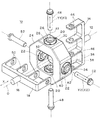
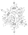
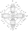
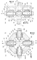
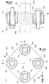
【解決手段】回転伝達カップリング10は、第1の軸直角方向Y1において対向配置されて駆動側部材14に接続される一対の第1ゴムブッシュ20と、該第1の軸直角方向に垂直な第2の軸直角方向Y2において対向配置されて従動側部材18に接続される一対の第2ゴムブッシュ22と、これらゴムブッシュ20,22を保持するカップリング本体24と、を備えてなる。一対の第1ゴムブッシュ20は、その軸方向X1を上記第1の軸直角方向Y1に一致させてカップリング本体24に保持されるとともに、一対の第2ゴムブッシュ22は、その軸方向X2を上記第2の軸直角方向Y2に一致させてカップリング本体24に保持されている。
【選択図】図1
Description
20…第1ゴムブッシュ 22…第2ゴムブッシュ 24…カップリング本体
30…第1ゴム弾性部 32…すぐり 38…第2ゴム弾性部
40…すぐり 42…第1取付孔 44…第2取付孔
O…回転軸 Y1…回転伝達カップリングの軸方向
Y1…回転伝達カップリングの第1の軸直角方向 Y2…第2の軸直角方向
A1…第1ゴムブッシュの軸芯 X1…第1ゴムブッシュの軸方向
A2…第2ゴムブッシュの軸芯 X2…第2ゴムブッシュの軸方向
Claims (3)
- 駆動側部材と該駆動側部材によって回転させられる従動側部材との間に介設されて両者を連結する回転伝達カップリングであって、
前記回転伝達カップリングの回転軸に垂直な第1の軸直角方向において、前記回転軸を挟んだ両側に配置されて前記駆動側部材に接続される一対の第1ゴムブッシュと、
前記第1の軸直角方向に垂直な第2の軸直角方向において、前記回転軸を挟んだ両側に配置されて前記従動側部材に接続される一対の第2ゴムブッシュと、
これら第1ゴムブッシュと第2ゴムブッシュを保持するカップリング本体と、
を備えてなり、
前記一対の第1ゴムブッシュは、当該第1ゴムブッシュの軸方向を前記第1の軸直角方向に一致させて前記カップリング本体に保持され、前記一対の第2ゴムブッシュは、当該第2ゴムブッシュの軸方向を前記第2の軸直角方向に一致させて前記カップリング本体に保持されたことを特徴とする回転伝達カップリング。 - 前記カップリング本体は、前記回転軸を取り囲む枠状部材であり、前記第1の軸直角方向における前記回転軸を挟んだ両側において当該第1の軸直角方向に貫通する一対の第1取付孔と、前記第2の軸直角方向における前記回転軸を挟んだ両側において当該第2の軸直角方向に貫通する一対の第2取付孔とを備え、前記一対の第1取付孔に前記一対の第1ゴムブッシュが挿入固定されるとともに、前記一対の第2取付孔に前記一対の第2ゴムブッシュが挿入固定されたことを特徴とする請求項1記載の回転伝達カップリング。
- 前記第1ゴムブッシュは、前記回転伝達カップリングの軸方向における前記第1ゴムブッシュの軸芯を挟んだ両側のゴム弾性部にすぐりが設けられ、前記第2ゴムブッシュは、前記回転伝達カップリングの軸方向における前記第2ゴムブッシュの軸芯を挟んだ両側のゴム弾性部にすぐりが設けられたことを特徴とする請求項1又は2記載の回転伝達カップリング。
Priority Applications (1)
| Application Number | Priority Date | Filing Date | Title |
|---|---|---|---|
| JP2010288546A JP5570967B2 (ja) | 2010-12-24 | 2010-12-24 | 回転伝達カップリング |
Applications Claiming Priority (1)
| Application Number | Priority Date | Filing Date | Title |
|---|---|---|---|
| JP2010288546A JP5570967B2 (ja) | 2010-12-24 | 2010-12-24 | 回転伝達カップリング |
Publications (2)
| Publication Number | Publication Date |
|---|---|
| JP2012137125A true JP2012137125A (ja) | 2012-07-19 |
| JP5570967B2 JP5570967B2 (ja) | 2014-08-13 |
Family
ID=46674696
Family Applications (1)
| Application Number | Title | Priority Date | Filing Date |
|---|---|---|---|
| JP2010288546A Expired - Fee Related JP5570967B2 (ja) | 2010-12-24 | 2010-12-24 | 回転伝達カップリング |
Country Status (1)
| Country | Link |
|---|---|
| JP (1) | JP5570967B2 (ja) |
Citations (4)
| Publication number | Priority date | Publication date | Assignee | Title |
|---|---|---|---|---|
| JPS5758128U (ja) * | 1980-09-24 | 1982-04-06 | ||
| JPH04341617A (ja) * | 1991-05-17 | 1992-11-27 | Tokai Rubber Ind Ltd | ステアリングカップリング |
| JP2003294053A (ja) * | 2002-03-29 | 2003-10-15 | Nippon Piston Ring Co Ltd | 偏心方向の移動を規制したユニバーサルジョイント |
| JP2008185195A (ja) * | 2007-01-31 | 2008-08-14 | Bridgestone Corp | 回転伝達カップリング及びインホイールモータシステム |
-
2010
- 2010-12-24 JP JP2010288546A patent/JP5570967B2/ja not_active Expired - Fee Related
Patent Citations (4)
| Publication number | Priority date | Publication date | Assignee | Title |
|---|---|---|---|---|
| JPS5758128U (ja) * | 1980-09-24 | 1982-04-06 | ||
| JPH04341617A (ja) * | 1991-05-17 | 1992-11-27 | Tokai Rubber Ind Ltd | ステアリングカップリング |
| JP2003294053A (ja) * | 2002-03-29 | 2003-10-15 | Nippon Piston Ring Co Ltd | 偏心方向の移動を規制したユニバーサルジョイント |
| JP2008185195A (ja) * | 2007-01-31 | 2008-08-14 | Bridgestone Corp | 回転伝達カップリング及びインホイールモータシステム |
Also Published As
| Publication number | Publication date |
|---|---|
| JP5570967B2 (ja) | 2014-08-13 |
Similar Documents
| Publication | Publication Date | Title |
|---|---|---|
| US7641010B2 (en) | In-wheel motor with high durability | |
| EP2818386B1 (en) | Electric power steering device and shaft coupler used therein | |
| US20070107959A1 (en) | In-wheel motor system | |
| US7955178B2 (en) | Power transmission damper for a torque limiter | |
| US7571784B2 (en) | Flexible coupling and in-wheel motor system | |
| JP2000508046A (ja) | 特に弾性ピボット及びサスペンション等のために、捩り自在で軸方向及び半径方向に弾性的に拘束するための機械的継手 | |
| JP2009046060A (ja) | 電動パワーステアリング装置の軸継手 | |
| CN108240416A (zh) | 扭转减振装置、飞轮及汽车传动系统 | |
| JP2618767B2 (ja) | ステアリングカップリング | |
| JP2007139195A (ja) | トーショナルダンパ及びトーショナルダンパを備えた装置 | |
| JP5570967B2 (ja) | 回転伝達カップリング | |
| WO2019131509A1 (ja) | 電気自動車用防振装置の配設構造 | |
| JP2012167714A (ja) | 回転伝達カップリング | |
| JP2016033411A (ja) | トーショナルラバーダンパ | |
| JP2012159111A (ja) | 捩りダンパ装置 | |
| CN212921686U (zh) | 全地形车的转向机构及全地形车 | |
| US20060183558A1 (en) | Driveshaft coupling | |
| CN111442062B (zh) | 减振盘组件 | |
| JP2006189095A (ja) | 弾性継手及び自動車用ホイールの連結構造 | |
| JP4028165B2 (ja) | マウントインシュレータ | |
| JP2001165219A (ja) | 防振ブッシュおよび防振ブッシュ組立体 | |
| JP2008185195A (ja) | 回転伝達カップリング及びインホイールモータシステム | |
| JPS60215123A (ja) | 防振ステアリングシヤフト | |
| JP6081072B2 (ja) | ハイブリッドシステムの動力伝達装置 | |
| JPS61201924A (ja) | 弾性軸継手 |
Legal Events
| Date | Code | Title | Description |
|---|---|---|---|
| A621 | Written request for application examination |
Free format text: JAPANESE INTERMEDIATE CODE: A621 Effective date: 20130806 |
|
| A131 | Notification of reasons for refusal |
Free format text: JAPANESE INTERMEDIATE CODE: A131 Effective date: 20140121 |
|
| A977 | Report on retrieval |
Free format text: JAPANESE INTERMEDIATE CODE: A971007 Effective date: 20140123 |
|
| A521 | Written amendment |
Free format text: JAPANESE INTERMEDIATE CODE: A523 Effective date: 20140314 |
|
| TRDD | Decision of grant or rejection written | ||
| A01 | Written decision to grant a patent or to grant a registration (utility model) |
Free format text: JAPANESE INTERMEDIATE CODE: A01 Effective date: 20140617 |
|
| A61 | First payment of annual fees (during grant procedure) |
Free format text: JAPANESE INTERMEDIATE CODE: A61 Effective date: 20140625 |
|
| R150 | Certificate of patent or registration of utility model |
Ref document number: 5570967 Country of ref document: JP Free format text: JAPANESE INTERMEDIATE CODE: R150 |
|
| LAPS | Cancellation because of no payment of annual fees |