以下、適宜図面を参照しつつ、本発明の遊技機の一実施形態に係るパチンコ遊技機1について説明する。
Hereinafter, a pachinko gaming machine 1 according to an embodiment of the gaming machine of the present invention will be described with reference to the drawings as appropriate.
[パチンコ遊技機1の概略構成]
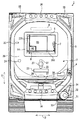
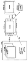
まず、パチンコ遊技機1の概略構成について説明する。図1は、パチンコ遊技機1の概略正面図である。図1に示されるように、パチンコ遊技機1は、遊技球が打ち出される遊技盤2と、遊技盤2を囲む枠部材3とを備えている。枠部材3は、遊技盤2の表面側(図1の紙面手前側)に遊技盤2と所定の間隔を隔てて平行に配置された透明なガラス板(不図示)を支持する部材であり、遊技盤2に対して蝶番(不図示)を介して開閉可能に構成されると共に、遊技盤2に対して着脱可能に構成されている。
[Schematic configuration of pachinko gaming machine 1]
First, a schematic configuration of the pachinko gaming machine 1 will be described. FIG. 1 is a schematic front view of a pachinko gaming machine 1. As shown in FIG. 1, the pachinko gaming machine 1 includes a game board 2 on which game balls are launched, and a frame member 3 surrounding the game board 2. The frame member 3 is a member that supports a transparent glass plate (not shown) disposed in parallel with the game board 2 at a predetermined interval on the front side of the game board 2 (the front side in FIG. 1). The game board 2 is configured to be openable and closable via a hinge (not shown) and is configured to be detachable from the game board 2.
枠部材3に支持されたガラス板と遊技盤2との間には、遊技球が移動する遊技領域20が形成されている。遊技者がハンドル31を握ってレバー32を時計方向へ回転させると、ハンドル31の回転角度に応じた打球力で不図示の発射装置から遊技球が発射される。図には示されていないが、遊技盤2には、発射装置から発射された遊技球を遊技領域20へ案内するガイド部材が設けられており、遊技球は、このガイド部材によって遊技領域20の上部位置へ案内される。遊技球は、遊技領域20に配置された不図示の遊技クギや風車等に接触することでその移動方向を変化させながら遊技盤2の表面に沿って落下する。
A game area 20 in which a game ball moves is formed between the glass plate supported by the frame member 3 and the game board 2. When the player holds the handle 31 and rotates the lever 32 in the clockwise direction, a game ball is launched from a launching device (not shown) with a hitting force corresponding to the rotation angle of the handle 31. Although not shown in the drawing, the game board 2 is provided with a guide member that guides the game ball launched from the launching device to the game area 20, and the game ball is stored in the game area 20 by the guide member. Guided to the upper position. The game ball falls along the surface of the game board 2 while changing its moving direction by coming into contact with a game nail (not shown) or a windmill arranged in the game area 20.
遊技領域20には、入賞や抽選に関する役物として、第1始動口21、第2始動口22、大入賞口23、普通入賞口24、及びゲート25が設けられている。また、遊技領域20における大入賞口23の下方には、始動口21,22、又は入賞口23,24に入らなかった遊技球を遊技領域20の外へ排出する排出口26が設けられている。
The game area 20 is provided with a first start port 21, a second start port 22, a large winning port 23, a normal winning port 24, and a gate 25, as winning items related to winning and lottery. In addition, a discharge port 26 for discharging game balls that have not entered the start ports 21 and 22 or the winning ports 23 and 24 to the outside of the gaming region 20 is provided below the big winning port 23 in the gaming region 20. .
第1始動口21及び第2始動口22は、後述する液晶表示器5の下方に設けられている。第1始動口21及び第2始動口22は、第1始動口21を第2始動口22の上側として所定の間隔を隔てて上下に並んで配置されている。パチンコ遊技機1では、第1始動口21又は第2始動口22に遊技球が入賞することで、賞球が払い出されると共に大当たり抽選が実行される。なお、以下の説明では、第1始動口21への遊技球の入賞を契機として実行される大当たり抽選を第1特別図柄抽選と呼び、第2始動口22への遊技球の入賞を契機として実行される大当たり抽選を第2特別図柄抽選と呼び、第1特別図柄抽選及び第2特別図柄抽選を総称して特別図柄抽選と呼ぶものとする。
The first start port 21 and the second start port 22 are provided below the liquid crystal display 5 described later. The first start port 21 and the second start port 22 are arranged side by side at a predetermined interval with the first start port 21 as the upper side of the second start port 22. In the pachinko gaming machine 1, when a game ball wins at the first start port 21 or the second start port 22, the prize ball is paid out and a big win lottery is executed. In the following description, the jackpot lottery executed when the game ball is won at the first start port 21 is called a first special symbol lottery, and is executed when the game ball is won at the second start port 22. The jackpot lottery performed is referred to as a second special symbol lottery, and the first special symbol lottery and the second special symbol lottery are collectively referred to as a special symbol lottery.
第1始動口21と第2始動口22との間には、チューリップの花を模した一対の羽根部材を有する電動チューリップ27が配置されている。電動チューリップ27は、一対の羽根部材が閉じた閉姿勢(図1参照)と、一対の羽根部材が開いた開姿勢(不図示)との間で姿勢変化可能に構成されており、不図示の電動ソレノイドが作動することによって閉姿勢から開姿勢に姿勢変化する。
Between the 1st starting port 21 and the 2nd starting port 22, the electric tulip 27 which has a pair of blade member imitating a tulip flower is arrange | positioned. The electric tulip 27 is configured to change its posture between a closed posture (see FIG. 1) in which the pair of blade members are closed and an open posture (not shown) in which the pair of blade members are open. When the electric solenoid operates, the posture changes from the closed posture to the open posture.
電動チューリップ27の一対の羽根部材が閉姿勢の状態では、第1始動口21を構成する部材及び電動チューリップ27によって第2始動口22への遊技球の進入経路が塞がれており、遊技球が第2始動口22へ入ることはない。これに対して、遊技球がゲート25を通過すると、普通図柄抽選(電動チューリップ27の開閉抽選)が実行され、この普通図柄抽選に当選すると、電動チューリップ27の一対の羽根部材が規定時間だけ開姿勢を維持した後に閉姿勢に戻る動作が規定回数行われる。このように、普通図柄抽選に当選することで、第2始動口22への遊技球の進入経路が開放されて、遊技球が第2始動口22に入賞可能となる。すなわち、第2特別図柄抽選の実行が可能な状態となる。なお、普通図柄抽選の当選確率、電動チューリップ27の動作に関する規定時間及び規定回数は、パチンコ遊技機1の遊技状態に応じて変更されることがある。
In a state where the pair of blade members of the electric tulip 27 is in the closed position, the entry path of the game ball to the second start port 22 is blocked by the member constituting the first start port 21 and the electric tulip 27, and the game ball Does not enter the second starting port 22. On the other hand, when the game ball passes through the gate 25, a normal symbol lottery (opening / closing lottery of the electric tulip 27) is executed, and when the normal symbol lottery is won, the pair of blade members of the electric tulip 27 is opened for a specified time. The operation of returning to the closed posture after maintaining the posture is performed a prescribed number of times. Thus, by winning the normal symbol lottery, the approach path of the game ball to the second start port 22 is released, and the game ball can win the second start port 22. That is, the second special symbol lottery can be executed. Note that the winning probability of the normal symbol lottery, the specified time and the specified number of times for the operation of the electric tulip 27 may be changed according to the gaming state of the pachinko gaming machine 1.
普通入賞口24は、ゲート25の下方に配置されている。普通入賞口24に遊技球が入賞した場合、抽選は実行されないが、第1始動口21や第2始動口22に遊技球が入賞した場合よりも多い賞球が払い出される。
The normal winning opening 24 is disposed below the gate 25. When a game ball wins the normal winning opening 24, the lottery is not executed, but more prize balls are paid out than when the game ball wins the first start opening 21 and the second start opening 22.
大入賞口23は、第2始動口22の下方に配置されている。大入賞口23は、特別図柄抽選の結果に応じて開放される。大入賞口23の開口部には、大入賞口23を開閉するプレートが設けられている。特別図柄抽選に当選していない状態では、このプレートが遊技盤2の表面と同一平面を形成する姿勢となっているために、大入賞口23に遊技球が入らない状態となっている。これに対して、特別図柄抽選に当選すると、プレートの下端側を軸としてプレートの上端側が遊技盤2の表面側へ傾倒して、大入賞口23が開放される。
The big prize opening 23 is arranged below the second start opening 22. The special winning opening 23 is opened according to the result of the special symbol lottery. A plate for opening and closing the big prize opening 23 is provided at the opening of the big prize opening 23. In a state where the special symbol lottery is not won, since the plate is in the same plane as the surface of the game board 2, the game ball does not enter the big winning opening 23. On the other hand, when the special symbol lottery is won, the upper end side of the plate is tilted toward the surface side of the game board 2 with the lower end side of the plate as an axis, and the special winning opening 23 is opened.
ここで、賞球の払い出しについて説明する。第1始動口21、第2始動口22、大入賞口23、及び普通入賞口24に遊技球が入って入賞すると、入賞した場所に応じた個数の賞球(遊技球)が払い出される。例えば、第1始動口21又は第2始動口22に遊技球が入賞すると4個の賞球が払い出され、大入賞口23に遊技球が入賞すると13個の賞球が払い出され、普通入賞口24に遊技球が入賞すると10個の賞球が払い出される。なお、遊技球がゲート25を通過しても賞球が払い出されることはない。
Here, the payout of prize balls will be described. When a game ball enters the first start port 21, the second start port 22, the big winning port 23, and the normal winning port 24 and wins, a number of award balls (game balls) corresponding to the winning place are paid out. For example, when a game ball is won at the first start port 21 or the second start port 22, four prize balls are paid out, and when a game ball is won at the big prize port 23, 13 prize balls are paid out. When a game ball wins the winning opening 24, 10 winning balls are paid out. Even if the game ball passes through the gate 25, the prize ball is not paid out.
遊技盤2の中央部には、演出のための各種の画像を表示する液晶表示器5及びEL表示器6が設けられている。液晶表示器5及びEL表示器6については、本発明の主要な構成であるため後に詳述する。
A liquid crystal display 5 and an EL display 6 for displaying various images for production are provided at the center of the game board 2. Since the liquid crystal display 5 and the EL display 6 are the main components of the present invention, they will be described in detail later.
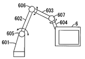
液晶表示器5と近接する位置に、各種の演出に用いられる盤ランプ8及び可動役物7が設けられている。盤ランプ8は、遊技者による遊技の進行に応じて発光することによって光による各種の演出を行う。可動役物7は、遊技盤2に対して可動に構成されており、例えば内蔵された発光素子を発光させながら回動することによって各種の演出を行う。なお、本実施形態では、遊技盤2に対して可動に構成された装飾役物が可動役物7のみである場合について説明するが、さらに他の可動役物が設けられていてもよい。
A panel lamp 8 and a movable accessory 7 used for various effects are provided at positions close to the liquid crystal display 5. The board lamp 8 emits light according to the progress of the game by the player, thereby performing various effects by light. The movable accessory 7 is configured to be movable with respect to the game board 2, and performs various effects by rotating, for example, a built-in light emitting element. In the present embodiment, the case where the decorative accessory configured to be movable with respect to the game board 2 is only the movable accessory 7 will be described, but another movable accessory may be provided.
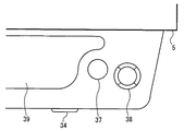
図2は、パチンコ遊技機1の一部を示す概略平面図である。図1及び図2に示されるように、枠部材3には、上記ハンドル31及びレバー32の他に、停止ボタン33、取り出しボタン34、スピーカ35、枠ランプ36、演出ボタン37、演出キー38、及び皿39が設けられている。
FIG. 2 is a schematic plan view showing a part of the pachinko gaming machine 1. As shown in FIGS. 1 and 2, the frame member 3 includes a stop button 33, a take-out button 34, a speaker 35, a frame lamp 36, an effect button 37, an effect key 38, in addition to the handle 31 and the lever 32. And a dish 39 are provided.
皿39は、枠部材3からパチンコ遊技機1の正面側へ突出するように設けられており、上述の発射装置へ供給される遊技球を一時的に溜めるものである。この皿39には、上述のように払い出された賞球が排出される。遊技者がハンドル31を握ってレバー32を時計方向へ回転させると、皿39に溜められた遊技球が発射装置へ供給されて、遊技領域20へ所定の時間間隔で発射される。この遊技球の発射は、遊技者が停止ボタン33を押下することによって一時的に停止される。
The tray 39 is provided so as to protrude from the frame member 3 to the front side of the pachinko gaming machine 1, and temporarily stores game balls supplied to the above-described launching device. The prize balls dispensed as described above are discharged to the plate 39. When the player grasps the handle 31 and rotates the lever 32 in the clockwise direction, the game balls stored in the tray 39 are supplied to the launching device and are launched into the game area 20 at predetermined time intervals. The launch of the game ball is temporarily stopped when the player presses the stop button 33.
取り出しボタン34は、皿39と近接する位置に設けられている。遊技者が取り出しボタン34を操作すると、皿39の下面の一部が開口されて、皿39に溜まった遊技球が皿39の下方に配置された不図示の箱へ落下する。なお、この皿39は、1つの皿によって構成されてもよいし、発射装置へ供給される遊技球及び賞球を溜める上皿と、賞球のみを溜める下皿との2つの皿によって構成されてもよい。
The take-out button 34 is provided at a position close to the plate 39. When the player operates the take-out button 34, a part of the lower surface of the tray 39 is opened, and the game balls accumulated on the tray 39 fall into a box (not shown) arranged below the tray 39. The dish 39 may be constituted by one dish, or by two dishes, an upper dish for collecting game balls and prize balls supplied to the launching device, and a lower dish for collecting only prize balls. May be.
スピーカ35は、楽曲や音声、効果音等を出力して音による演出を行う。枠ランプ36は、点灯又は点滅のパターンの変更、発光色の変更、光の照射方向の変更等の光による各種の演出を行う。
The speaker 35 outputs music, sound, sound effects, etc., and performs effects by sound. The frame lamp 36 performs various effects by light, such as changing a lighting or blinking pattern, changing a light emission color, and changing a light irradiation direction.
演出ボタン37及び演出キー38は、それぞれ遊技者が演出に対する操作入力を行うために設けられている。演出ボタン37は、皿39の横に設けられている。演出キー38は、中央キーと中央キーの周辺に配列された複数(ここでは4つ)の周辺キーとを有しており、演出ボタン37に隣接配置されている。後述するが、遊技者が演出キー38の周辺キーを操作することによって、液晶表示器5に表示された複数の選択肢の中からいずれかを選択指示することができる。このように、演出キー38は、遊技者が操作情報を入力するための操作手段として機能する。
The effect button 37 and the effect key 38 are provided for the player to input an operation for the effect, respectively. The effect button 37 is provided on the side of the plate 39. The effect key 38 has a center key and a plurality of (here, four) peripheral keys arranged around the center key, and is arranged adjacent to the effect button 37. As will be described later, the player can select and instruct one of a plurality of options displayed on the liquid crystal display 5 by operating the peripheral keys of the effect key 38. Thus, the production key 38 functions as an operation means for the player to input operation information.
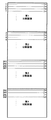
図3は、図1における表示器4の拡大図である。表示器4は、上述した特別図柄抽選や普通図柄抽選の結果や保留数に関する情報を表示するものである。図3に示されるように、表示器4は、第1特別図柄表示器41、第2特別図柄表示器42、第1特別図柄保留表示器43、第2特別図柄保留表示器44、普通図柄表示器45、普通図柄保留表示器46、及び遊技状態表示器47を備えている。
FIG. 3 is an enlarged view of the display 4 in FIG. The display device 4 displays information on the result of the special symbol lottery or the normal symbol lottery described above and the number of holds. As shown in FIG. 3, the display 4 includes a first special symbol display 41, a second special symbol display 42, a first special symbol hold indicator 43, a second special symbol hold indicator 44, and a normal symbol display. A device 45, a normal symbol holding display 46, and a game state display 47 are provided.
第1特別図柄表示器41は、第1始動口21への遊技球の入賞を契機として特別図柄を変動表示してから第1特別図柄抽選の結果を示す特別図柄を停止表示する。第1特別図柄保留表示器43は、第1特別図柄抽選の保留数を表示する。第2特別図柄表示器42は、第2始動口22への遊技球の入賞を契機として特別図柄を変動表示してから第2特別図柄抽選の結果を示す特別図柄を停止表示する。第2特別図柄保留表示器44は、第2特別図柄抽選の保留数を表示する。普通図柄表示器45は、遊技球がゲート25を通過したことを契機として始動した普通図柄抽選の結果を表示する。普通図柄保留表示器46は、普通図柄抽選の保留数を表示する。遊技状態表示器47は、パチンコ遊技機1の電源投入時点における遊技状態(例えば、通常遊技状態、確変遊技状態、時短遊技状態、潜伏遊技状態)を表示する。
The first special symbol display 41 variably displays the special symbol in response to the winning of the game ball at the first starting port 21, and then stops and displays the special symbol indicating the result of the first special symbol lottery. The first special symbol hold indicator 43 displays the number of holds in the first special symbol lottery. The second special symbol display 42 variably displays the special symbol in response to the winning of the game ball at the second starting port 22, and then stops and displays the special symbol indicating the result of the second special symbol lottery. The second special symbol hold indicator 44 displays the number of holds in the second special symbol lottery. The normal symbol display 45 displays the result of the normal symbol lottery started when the game ball has passed through the gate 25. The normal symbol hold indicator 46 displays the number of normal symbol lottery holds. The gaming state display 47 displays a gaming state (for example, a normal gaming state, a probability variation gaming state, a short-time gaming state, a latent gaming state) at the time when the power of the pachinko gaming machine 1 is turned on.
ここまでパチンコ遊技機1の概略構成について説明したが、上述したパチンコ遊技機1の構成は単なる一例であって、遊技盤2の盤面構成等は適宜変更されてもよい。例えば本発明に係る遊技機が右打ちが必要なパチンコ遊技機に適用される場合には、大入賞口23やゲート25等を液晶表示器5に対して右側の遊技領域20に配置するといった変更が行われる。
Although the schematic configuration of the pachinko gaming machine 1 has been described so far, the configuration of the pachinko gaming machine 1 described above is merely an example, and the board surface configuration and the like of the gaming board 2 may be changed as appropriate. For example, when the gaming machine according to the present invention is applied to a pachinko gaming machine that needs to be right-handed, a change is made such that the big winning opening 23, the gate 25, etc. are arranged in the gaming area 20 on the right side with respect to the liquid crystal display 5. Is done.
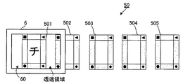
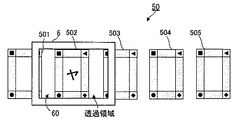
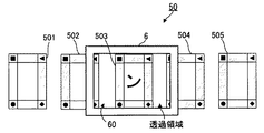
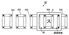
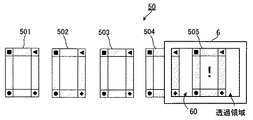
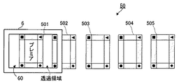
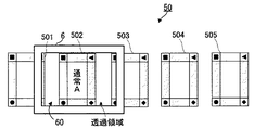
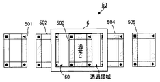
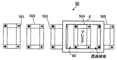
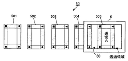
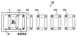
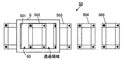
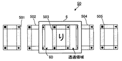
ところで、液晶表示器5が遊技者にとって視認し易い位置に固定されているので、特別図柄抽選に当選しない期間が長時間続いたとき等に遊技者の視点が固定され易く、遊技が単調になるおそれがある。そこで、本実施形態に係るパチンコ遊技機1は、裏返されたカードを液晶画面50に表示させた状態で、各カードの手前を通過するようにEL画面60を移動させながら、移動過程でEL画面60を通して視認される各カードを表側から見た画像をEL画面60に表示するといった興趣性の高い表示演出を行うことで、移動するEL画面60に遊技者の視線を誘導可能に構成されている。以下、このような効果的な表示演出を実現するためのパチンコ遊技機1の構成及び動作について説明する。
By the way, since the liquid crystal display 5 is fixed at a position where it is easy for the player to visually recognize, the player's viewpoint is easily fixed when the period not winning the special symbol lottery lasts for a long time, and the game becomes monotonous. There is a fear. Therefore, the pachinko gaming machine 1 according to the present embodiment moves the EL screen 60 so as to pass in front of each card in a state in which the reversed card is displayed on the liquid crystal screen 50, while the EL screen 60 is moved. It is configured such that the player's line of sight can be guided to the moving EL screen 60 by performing a highly interesting display effect such as displaying on the EL screen 60 an image of each card viewed through 60 from the front side. . Hereinafter, the configuration and operation of the pachinko gaming machine 1 for realizing such an effective display effect will be described.
[液晶表示器5の構成]
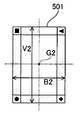
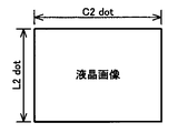
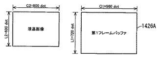
液晶表示器5(本発明の第1画像表示器の一例)は、遊技盤2を支持するパチンコ遊技機1の筐体に固定されている。このため、液晶表示器5は、遊技盤2に対して固定されている。液晶表示器5としては、例えば垂直方向11の画素数が「600」で、水平方向12の画素数が「800」という画面解像度(垂直画素数×水平画素数)の液晶画面50(本発明の第1表示画面の一例)を有する液晶ディスプレイが使用される。液晶表示器5は、後述する画像音響制御部140(図7参照)から出力される画像を液晶画面50に表示する。液晶画面50には、例えば、特別図柄抽選の結果を報知するための装飾図柄、予告演出を行うキャラクタやアイテム、特別図柄抽選が保留されていることを示す保留表示画像等の各種表示オブジェクトが表示される。このような各種表示オブジェクトの中には、上述したようにEL画面60を用いた演出時に表示されるカード(例えば、図20A〜図20Eを参照)を示す画像も含まれる。
[Configuration of Liquid Crystal Display 5]
The liquid crystal display 5 (an example of the first image display according to the present invention) is fixed to the housing of the pachinko gaming machine 1 that supports the game board 2. For this reason, the liquid crystal display 5 is fixed to the game board 2. As the liquid crystal display 5, for example, a liquid crystal screen 50 having a screen resolution (vertical pixel number × horizontal pixel number) of “600” in the vertical direction 11 and “800” in the horizontal direction 12 (in the present invention). A liquid crystal display having an example of a first display screen is used. The liquid crystal display 5 displays an image output from an image sound control unit 140 (see FIG. 7) described later on the liquid crystal screen 50. On the liquid crystal screen 50, for example, various display objects such as a decorative symbol for notifying the result of the special symbol lottery, a character or item for performing a notice effect, a hold display image indicating that the special symbol lottery is put on hold are displayed. Is done. Such various display objects include an image showing a card (for example, see FIGS. 20A to 20E) displayed at the time of production using the EL screen 60 as described above.
[EL表示器6の構成]
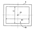
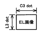
EL表示器6(本発明の第2画像表示器の一例)は、液晶表示器5の前面側に液晶画面50と所定の間隔を隔てて配置されており、後述する駆動機構10を介して伝達される第1ステッピングモータ29及び第2ステッピングモータ30の駆動力を受けて液晶画面50の表面に沿って上下左右に移動可能である。本実施形態におけるEL表示器6は、透明なEL画面60(本発明の第2表示画面の一例)に画像を単色表示する透明ELディスプレイである。EL画面60は、樹脂製のフレーム61に形成された開口部に嵌め込まれることによってフレーム61に固定されている。EL画面60としては、例えば垂直方向11の画素数が「240」で、水平方向12の画素数が「320」という画面解像度を有するものが使用される。従って、液晶表示器5及びEL表示器6は、EL画面60よりも液晶画面50の方が画面解像度が大きくなるように構成されている。
[Configuration of EL Display 6]
The EL display 6 (an example of the second image display of the present invention) is disposed on the front side of the liquid crystal display 5 with a predetermined distance from the liquid crystal screen 50, and is transmitted via a drive mechanism 10 described later. The first stepping motor 29 and the second stepping motor 30 that are driven can be moved up and down and left and right along the surface of the liquid crystal screen 50. The EL display 6 in this embodiment is a transparent EL display that displays an image in a single color on a transparent EL screen 60 (an example of the second display screen of the present invention). The EL screen 60 is fixed to the frame 61 by being fitted into an opening formed in a resin frame 61. As the EL screen 60, for example, a screen having a screen resolution of “240” in the vertical direction 11 and “320” in the horizontal direction 12 is used. Accordingly, the liquid crystal display 5 and the EL display 6 are configured such that the screen resolution of the liquid crystal screen 50 is larger than that of the EL screen 60.
EL表示器6として透過型のELディスプレイが使用されるので、EL画面60に画像が表示された状態であっても、遊技者がEL表示器6の裏面側に位置するオブジェクト(液晶画面50に表示された上述した表示オブジェクト、可動役物7等)をEL画面60を通して視認することができる。
Since a transmissive EL display is used as the EL display 6, even if an image is displayed on the EL screen 60, an object (on the liquid crystal screen 50) the player is positioned on the back side of the EL display 6. The displayed display object, movable accessory 7 and the like described above can be viewed through the EL screen 60.
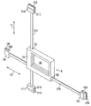
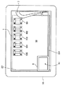
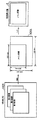
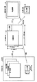
[駆動機構10の構成及び動作]
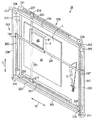
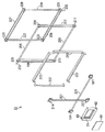
次に、図4〜図6を参照しつつ、EL表示器6を移動させる駆動機構10について説明する。図4は、駆動機構10の構成を示す斜視図であり、液晶画面50に表示された表示オブジェクトをEL画面60を通して視認可能な位置にEL表示器6が位置した状態を示している。図5は、駆動機構10の分解斜視図である。図6は、EL表示器6の拡大斜視図である。
[Configuration and Operation of Drive Mechanism 10]
Next, the drive mechanism 10 that moves the EL display 6 will be described with reference to FIGS. FIG. 4 is a perspective view showing the configuration of the driving mechanism 10 and shows a state in which the EL display 6 is located at a position where the display object displayed on the liquid crystal screen 50 can be visually recognized through the EL screen 60. FIG. 5 is an exploded perspective view of the drive mechanism 10. FIG. 6 is an enlarged perspective view of the EL display 6.
駆動機構10は、EL表示器6を液晶画面50に沿って上下左右に移動させるものである。本実施形態においては、駆動機構10は、第1ステッピングモータ29(図7参照)の駆動力をEL表示器6に伝達して、EL表示器6を液晶画面50に沿って垂直方向11(図1参照)に移動させる昇降駆動機構200と、第2ステッピングモータ30(図7参照)の駆動力をEL表示器6に伝達して、EL表示器6を液晶画面50に沿って水平方向12(図1参照)に移動させるスライド駆動機構220とから構成されている。
The drive mechanism 10 moves the EL display 6 vertically and horizontally along the liquid crystal screen 50. In the present embodiment, the drive mechanism 10 transmits the driving force of the first stepping motor 29 (see FIG. 7) to the EL display 6, and causes the EL display 6 to move along the liquid crystal screen 50 in the vertical direction 11 (FIG. 1) and the driving force of the second stepping motor 30 (see FIG. 7) is transmitted to the EL display 6, and the EL display 6 is moved along the liquid crystal screen 50 in the horizontal direction 12 (see FIG. And a slide drive mechanism 220 that is moved to (see FIG. 1).
昇降駆動機構200は、大別して、第1支持部材201、ガイド部材202、ガイド部材203、第1回転軸204、第2回転軸205、第1駆動ベルト206、及び第2駆動ベルト207を備えている。
The elevating drive mechanism 200 includes a first support member 201, a guide member 202, a guide member 203, a first rotating shaft 204, a second rotating shaft 205, a first driving belt 206, and a second driving belt 207. Yes.
第1支持部材201は、水平方向12を長手方向とする薄い板状部材である。この第1支持部材201は、図1に示されるように、液晶表示器5の液晶画面50の手前に配置されるため、液晶画面50に表示された画像の視認性の低下を最低限に抑えるために、透明な樹脂で形成されている。EL表示器6のフレーム61には、水平方向12に貫通する挿通孔62(図5及び図6参照)が形成されており、第1支持部材201は、挿通孔62に挿通されることによってフレーム61を水平方向12へ移動可能に支持する。
The first support member 201 is a thin plate-like member having the horizontal direction 12 as a longitudinal direction. As shown in FIG. 1, the first support member 201 is disposed in front of the liquid crystal screen 50 of the liquid crystal display 5, so that a reduction in the visibility of an image displayed on the liquid crystal screen 50 is minimized. Therefore, it is formed of a transparent resin. An insertion hole 62 (see FIGS. 5 and 6) penetrating in the horizontal direction 12 is formed in the frame 61 of the EL display 6, and the first support member 201 is inserted into the insertion hole 62 so that the frame 61 is supported so as to be movable in the horizontal direction 12.
図6に示されるように、第1支持部材201は、その一端側に連結部材194が固定されると共に、その他端側に連結部材197が固定されている。連結部材194は、ガイド部材202(図5参照)が挿通される円筒状の挿通孔195と、第1駆動ベルト206(図5参照)を挟持する挟持片196とを有している。ガイド部材202は、断面外形が円形の棒状部材であり、その長手方向が垂直方向11と一致するようにパチンコ遊技機1の筐体に固定されている。ガイド部材202の外径寸法は、挿通孔195の内径寸法よりも若干小さく設定されており、連結部材194は、挿通孔195にガイド部材202が挿通されることによって、垂直方向11へ移動可能にガイド部材202によって支持される。
As shown in FIG. 6, the first support member 201 has a connecting member 194 fixed to one end thereof and a connecting member 197 fixed to the other end thereof. The connecting member 194 includes a cylindrical insertion hole 195 through which the guide member 202 (see FIG. 5) is inserted, and a clamping piece 196 that clamps the first drive belt 206 (see FIG. 5). The guide member 202 is a rod-shaped member having a circular cross-sectional outer shape, and is fixed to the housing of the pachinko gaming machine 1 so that the longitudinal direction thereof coincides with the vertical direction 11. The outer diameter dimension of the guide member 202 is set slightly smaller than the inner diameter dimension of the insertion hole 195, and the connecting member 194 is movable in the vertical direction 11 when the guide member 202 is inserted into the insertion hole 195. Supported by the guide member 202.
連結部材197は、連結部材194と同形状の部材であって、ガイド部材203(図5参照)が挿通される挿通孔198と、第2駆動ベルト207(図5参照)を挟持する挟持片199とを有している。ガイド部材203は、ガイド部材202と同形状の部材であって、ガイド部材202と所定の間隔を隔てて対向するようにパチンコ遊技機1の筐体に固定されている。連結部材197は、挿通孔198にガイド部材203が挿通されることによって、垂直方向11へ移動可能にガイド部材203によって支持される。
The connecting member 197 is a member having the same shape as that of the connecting member 194, and a holding piece 199 that holds the insertion hole 198 through which the guide member 203 (see FIG. 5) is inserted and the second drive belt 207 (see FIG. 5). And have. The guide member 203 is a member having the same shape as the guide member 202 and is fixed to the housing of the pachinko gaming machine 1 so as to face the guide member 202 with a predetermined interval. The connecting member 197 is supported by the guide member 203 so as to be movable in the vertical direction 11 by inserting the guide member 203 through the insertion hole 198.
このように連結部材194及び連結部材197がガイド部材202及びガイド部材203に支持されているので、第1支持部材201は、垂直方向11へスライド可能である。
Thus, since the connecting member 194 and the connecting member 197 are supported by the guide member 202 and the guide member 203, the first support member 201 can slide in the vertical direction 11.
ガイド部材202,203の上側に第1回転軸204が設けられると共に、ガイド部材202,203の下側に第2回転軸205が設けられている(図4参照)。第1回転軸204及び第2回転軸205は、それぞれ軸方向が水平方向12と一致するように、不図示の軸受けに回転可能に支持されている。図5に示されるように、第1回転軸204は、その一端側にギヤ212及びプーリ208が固定されると共に、その他端にプーリ209が固定されている。第2回転軸205は、その一端にプーリ210が固定されると共に、その他端にプーリ211が固定されている。
A first rotating shaft 204 is provided above the guide members 202 and 203, and a second rotating shaft 205 is provided below the guide members 202 and 203 (see FIG. 4). The first rotating shaft 204 and the second rotating shaft 205 are rotatably supported by a bearing (not shown) so that the axial direction thereof coincides with the horizontal direction 12. As shown in FIG. 5, the first rotating shaft 204 has a gear 212 and a pulley 208 fixed to one end thereof, and a pulley 209 fixed to the other end. The second rotating shaft 205 has a pulley 210 fixed to one end thereof and a pulley 211 fixed to the other end thereof.
プーリ208とプーリ210との間には、内側に歯が形成された無端環状の第1駆動ベルト206が張り渡されている。プーリ209とプーリ211との間には、第1駆動ベルト206と同じ構成の第2駆動ベルト207が張り渡されている。
Between the pulley 208 and the pulley 210, an endless first drive belt 206 having teeth formed on the inside is stretched. A second drive belt 207 having the same configuration as the first drive belt 206 is stretched between the pulley 209 and the pulley 211.
第1回転軸204のギヤ212(図4参照)には、第1ステッピングモータ29(図7参照)の駆動力が入力される。これにより、ギヤ212が固定された第1回転軸204が回転する。プーリ208〜211の外周には、第1駆動ベルト206及び第2駆動ベルト207の歯と噛合する歯が形成されており、第1回転軸204の回転力がプーリ208,209を介して第1駆動ベルト206及び第2駆動ベルト207に伝達される。その結果、第1駆動ベルト206及び第2駆動ベルト207が周運動すると共に、第1回転軸204及び第2回転軸205が同期回転する。この第1駆動ベルト206及び第2駆動ベルト207には、第1支持部材201の両端に固定された連結部材194,197が挟持片196,199によって固定されているので、第1ステッピングモータ29の駆動力が第1支持部材201にも伝達されて、第1支持部材201に支持されたEL表示器6が垂直方向11へ移動する。なお、第1ステッピングモータ29の回転方向を正回転又は逆回転に切り換えることで、垂直方向11におけるEL表示器6の移動方向を切り換えることができる。
The driving force of the first stepping motor 29 (see FIG. 7) is input to the gear 212 (see FIG. 4) of the first rotating shaft 204. Thereby, the 1st rotating shaft 204 to which the gear 212 was fixed rotates. Teeth that mesh with the teeth of the first drive belt 206 and the second drive belt 207 are formed on the outer circumferences of the pulleys 208 to 211, and the rotational force of the first rotating shaft 204 is first via the pulleys 208 and 209. It is transmitted to the drive belt 206 and the second drive belt 207. As a result, the first drive belt 206 and the second drive belt 207 move circumferentially, and the first rotation shaft 204 and the second rotation shaft 205 rotate synchronously. Since the connecting members 194 and 197 fixed to both ends of the first support member 201 are fixed to the first drive belt 206 and the second drive belt 207 by sandwiching pieces 196 and 199, the first stepping motor 29 The driving force is also transmitted to the first support member 201 and the EL display 6 supported by the first support member 201 moves in the vertical direction 11. Note that the direction of movement of the EL display 6 in the vertical direction 11 can be switched by switching the rotation direction of the first stepping motor 29 to forward rotation or reverse rotation.
一方、スライド駆動機構220は、大別して、第2支持部材221、ガイド部材222、ガイド部材223、第1回転軸224、第2回転軸225、第1駆動ベルト226、及び第2駆動ベルト227を備えている。
On the other hand, the slide drive mechanism 220 is roughly divided into a second support member 221, a guide member 222, a guide member 223, a first rotation shaft 224, a second rotation shaft 225, a first drive belt 226, and a second drive belt 227. I have.
第2支持部材221は、垂直方向11を長手方向とする薄い板状部材である。この第2支持部材221は、第1支持部材201と同様に、透明な樹脂で形成されている。EL表示器6のフレーム61には、垂直方向11に貫通する挿通孔63(図5及び図6参照)が形成されており、第2支持部材221は、挿通孔63に挿通されることによってフレーム61を垂直方向11へ移動可能に支持する。
The second support member 221 is a thin plate member whose longitudinal direction is the vertical direction 11. Similar to the first support member 201, the second support member 221 is formed of a transparent resin. An insertion hole 63 (see FIGS. 5 and 6) penetrating in the vertical direction 11 is formed in the frame 61 of the EL display 6, and the second support member 221 is inserted into the insertion hole 63 so that the frame 61 is supported so as to be movable in the vertical direction 11.
図6に示されるように、第2支持部材221は、その一端側に連結部材214が固定されると共に、その他端側に連結部材217が固定されている。連結部材214は、ガイド部材222(図5参照)が挿通される円筒状の挿通孔215と、第2駆動ベルト227(図5参照)を挟持する挟持片216とを有している。ガイド部材222は、断面外形が円形の棒状部材であり、その長手方向が水平方向12と一致するように、パチンコ遊技機1の筐体に固定されている。ガイド部材222の外径寸法は、挿通孔215の内径寸法よりも若干小さく設定されており、連結部材214は、挿通孔215にガイド部材222が挿通されることによって、水平方向12へ移動可能にガイド部材222によって支持される。
As shown in FIG. 6, the second support member 221 has a connecting member 214 fixed to one end thereof and a connecting member 217 fixed to the other end thereof. The connecting member 214 has a cylindrical insertion hole 215 through which the guide member 222 (see FIG. 5) is inserted, and a holding piece 216 that holds the second drive belt 227 (see FIG. 5). The guide member 222 is a rod-shaped member having a circular cross-sectional outer shape, and is fixed to the housing of the pachinko gaming machine 1 so that the longitudinal direction thereof coincides with the horizontal direction 12. The outer diameter dimension of the guide member 222 is set slightly smaller than the inner diameter dimension of the insertion hole 215, and the connecting member 214 is movable in the horizontal direction 12 by inserting the guide member 222 into the insertion hole 215. Supported by the guide member 222.
連結部材217は、連結部材214と同形状の部材であって、ガイド部材223(図5参照)が挿通される挿通孔218と、第1駆動ベルト226(図5参照)を挟持する挟持片219とを有している。ガイド部材223は、ガイド部材222と同形状の部材であって、ガイド部材222と所定の間隔を隔てて対向するようにパチンコ遊技機1の筐体に固定されている。連結部材217は、挿通孔218にガイド部材223が挿通されることによって、水平方向12へ移動可能にガイド部材223によって支持される。
The connecting member 217 is a member having the same shape as the connecting member 214, and includes an insertion hole 218 through which the guide member 223 (see FIG. 5) is inserted, and a holding piece 219 that holds the first drive belt 226 (see FIG. 5). And have. The guide member 223 is a member having the same shape as the guide member 222, and is fixed to the housing of the pachinko gaming machine 1 so as to face the guide member 222 with a predetermined interval. The connecting member 217 is supported by the guide member 223 so as to be movable in the horizontal direction 12 by inserting the guide member 223 through the insertion hole 218.
このように連結部材214及び連結部材217がガイド部材222及びガイド部材223に支持されているので、第2支持部材221は、水平方向12へスライド可能である。
Thus, since the connecting member 214 and the connecting member 217 are supported by the guide member 222 and the guide member 223, the second support member 221 is slidable in the horizontal direction 12.
水平方向12におけるガイド部材222,223の外側に、第1回転軸224及び第2回転軸225が設けられている(図4参照)。第1回転軸224及び第2回転軸225は、それぞれ軸方向が垂直方向11と一致するように、不図示の軸受けに回転可能に支持されている。図5に示されるように、第1回転軸224は、その一端側にギヤ232及びプーリ228が固定されると共に、その他端にプーリ229が固定されている。第2回転軸225は、その一端にプーリ230が固定されると共に、その他端にプーリ231が固定されている。
A first rotating shaft 224 and a second rotating shaft 225 are provided outside the guide members 222 and 223 in the horizontal direction 12 (see FIG. 4). The first rotating shaft 224 and the second rotating shaft 225 are rotatably supported by a bearing (not shown) such that the axial direction thereof coincides with the vertical direction 11. As shown in FIG. 5, the first rotating shaft 224 has a gear 232 and a pulley 228 fixed to one end thereof, and a pulley 229 fixed to the other end. The second rotating shaft 225 has a pulley 230 fixed to one end and a pulley 231 fixed to the other end.
プーリ228とプーリ230との間には、内側に歯が形成された無端環状の第1駆動ベルト226が張り渡されている。プーリ229とプーリ231との間には、第1駆動ベルト226と同じ構成の第2駆動ベルト227が張り渡されている。
Between the pulley 228 and the pulley 230, an endless annular first drive belt 226 having teeth formed inside is stretched. A second drive belt 227 having the same configuration as the first drive belt 226 is stretched between the pulley 229 and the pulley 231.
第1回転軸224のギヤ232(図4参照)には、第2ステッピングモータ30(図7参照)の駆動力が入力される。これにより、ギヤ232が固定された第1回転軸224が回転する。プーリ228〜231の外周には、第1駆動ベルト226及び第2駆動ベルト227の歯と噛合する歯が形成されており、第1回転軸224の回転力がプーリ228,229を介して第1駆動ベルト226及び第2駆動ベルト227に伝達される。その結果、第1駆動ベルト226及び第2駆動ベルト227が周運動すると共に、第1回転軸224及び第2回転軸225が同期回転する。この第1駆動ベルト226及び第2駆動ベルト227には、第2支持部材221の両端に固定された連結部材214,217が挟持片216,219によって固定されているので、第2ステッピングモータ30の駆動力が第2支持部材221にも伝達されて、第2支持部材221に支持されたEL表示器6が水平方向12へ移動する。なお、第2ステッピングモータ30の回転方向を正回転又は逆回転に切り換えることで、水平方向12におけるEL表示器6の移動方向を切り換えることができる。
The driving force of the second stepping motor 30 (see FIG. 7) is input to the gear 232 (see FIG. 4) of the first rotating shaft 224. Thereby, the 1st rotating shaft 224 to which the gear 232 was fixed rotates. Teeth that mesh with the teeth of the first drive belt 226 and the second drive belt 227 are formed on the outer circumferences of the pulleys 228 to 231, and the rotational force of the first rotating shaft 224 is first via the pulleys 228 and 229. It is transmitted to the drive belt 226 and the second drive belt 227. As a result, the first drive belt 226 and the second drive belt 227 move circumferentially, and the first rotation shaft 224 and the second rotation shaft 225 rotate synchronously. Since the first driving belt 226 and the second driving belt 227 have connecting members 214 and 217 fixed to both ends of the second support member 221 fixed by sandwiching pieces 216 and 219, the second stepping motor 30 The driving force is also transmitted to the second support member 221 so that the EL display 6 supported by the second support member 221 moves in the horizontal direction 12. Note that the moving direction of the EL display 6 in the horizontal direction 12 can be switched by switching the rotation direction of the second stepping motor 30 to forward rotation or reverse rotation.
このように、EL表示器6は、昇降駆動機構200によって垂直方向11へ移動し、スライド駆動機構220によって水平方向12へ移動する。なお、第1支持部材201及び第2支持部材221を除く駆動機構10の各構成部材は、液晶表示器5等が設けられた領域と遊技領域20とを区画する化粧カバー14(図1参照)によって覆われているために、図1には現れていない。
Thus, the EL display 6 moves in the vertical direction 11 by the lifting drive mechanism 200 and moves in the horizontal direction 12 by the slide drive mechanism 220. In addition, each component of the drive mechanism 10 excluding the first support member 201 and the second support member 221 is a decorative cover 14 that partitions the region where the liquid crystal display 5 and the like are provided from the game region 20 (see FIG. 1). 1 does not appear in FIG.
[パチンコ遊技機1の制御装置の構成]
遊技盤2の裏面側(図1の紙面奥側)には、賞球として払い出される遊技球を溜めておく球タンクの他に、パチンコ遊技機1の動作を制御する制御装置が設けられている。図には示されていないが、この制御装置は、メイン基板及びサブ基板を有している。メイン基板は、内部抽選や当選の判定等を行う遊技制御部100として機能するメイン制御基板、賞球の払い出しを制御する払出制御部120として機能する払出制御基板等から構成されている。このメイン基板は、メイン基板が改変された場合にその痕跡が残るように、透明部材で構成されたケース内に密閉状態で配置されている。一方のサブ基板は、演出を統括的に制御する演出制御部130として機能する演出制御基板、画像や音による演出を制御する画像音響制御部140として機能する画像音響制御基板、及び各種のランプ(枠ランプ36や盤ランプ8)や可動役物7による演出を制御するランプ制御部150として機能するランプ制御基板等から構成されている。
[Configuration of control device of pachinko gaming machine 1]
On the back side of the game board 2 (the back side in FIG. 1), a control device for controlling the operation of the pachinko gaming machine 1 is provided in addition to a ball tank for storing game balls to be paid out as prize balls. . Although not shown in the figure, the control device has a main board and a sub board. The main board includes a main control board that functions as a game control unit 100 that performs internal lottery and determination of winning, a payout control board that functions as a payout control unit 120 that controls payout of prize balls. The main board is disposed in a sealed state in a case made of a transparent member so that a trace remains when the main board is modified. One of the sub-boards is an effect control board that functions as an effect control section 130 that comprehensively controls the effects, an image sound control board that functions as an image sound control section 140 that controls effects by images and sounds, and various lamps ( The lamp control board 150 functions as a lamp control unit 150 that controls the effects of the frame lamp 36, the panel lamp 8) and the movable accessory 7.
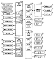
以下、図7を参照しつつ、パチンコ遊技機1の制御装置の構成について説明する。ここで、図7は、パチンコ遊技機1の制御装置の構成例を示すブロック図である。図7に示されるように、パチンコ遊技機1の制御装置は、遊技制御部100、払出制御部120、演出制御部130、画像音響制御部140、及びランプ制御部150を備えている。
Hereinafter, the configuration of the control device of the pachinko gaming machine 1 will be described with reference to FIG. Here, FIG. 7 is a block diagram illustrating a configuration example of the control device of the pachinko gaming machine 1. As shown in FIG. 7, the control device of the pachinko gaming machine 1 includes a game control unit 100, a payout control unit 120, an effect control unit 130, an image sound control unit 140, and a lamp control unit 150.
[遊技制御部100の構成]
遊技制御部100は、CPU101、ROM102、及びRAM103を備えている。CPU101は、ROM102に記憶されたプログラムに基づいて、内部抽選や当選の判定等の払い出し賞球数に関連する各種の演算処理を行う。ROM102には、上記プログラムの他に、第1特別図柄抽選の最大保留数Umax1、第2特別図柄抽選の最大保留数Umax2等が記憶されている。RAM103は、CPU101が上記プログラムを実行する際に用いる各種データを一時的に記憶する記憶領域又はデータ処理などの作業領域として使用される。この遊技制御部100の主な機能は以下の通りである。
[Configuration of Game Control Unit 100]
The game control unit 100 includes a CPU 101, a ROM 102, and a RAM 103. Based on the program stored in the ROM 102, the CPU 101 performs various arithmetic processes related to the number of payout prize balls such as internal lottery and determination of winning. In addition to the above programs, the ROM 102 stores the maximum number of holdings Umax1 for the first special symbol lottery, the maximum number of holdings Umax2 for the second special symbol lottery, and the like. The RAM 103 is used as a storage area for temporarily storing various data used when the CPU 101 executes the program, or as a work area for data processing. The main functions of the game control unit 100 are as follows.
遊技制御部100は、第1始動口21又は第2始動口22に遊技球が入賞すると特別図柄抽選を実行し、特別図柄抽選での当選か否かを示す判定結果データを演出制御部130へ送信する。また、遊技制御部100は、特別図柄抽選に応じて決定した当選確率の変動設定(例えば300分の1から30分の1への変動設定)を示すデータ、特別図柄変動時間の短縮設定を示すデータ、普通図柄抽選に応じて決定した普通図柄変動時間の短縮設定を示すデータ等を演出制御部130へ送信する。
The game control unit 100 executes a special symbol lottery when a game ball wins at the first start port 21 or the second start port 22, and determines result data indicating whether or not the special symbol lottery is won to the effect control unit 130. Send. In addition, the game control unit 100 indicates data indicating the variation setting of the winning probability determined according to the special symbol lottery (for example, variation setting from 1/300 to 1/30), and shortening the special symbol variation time setting. Data, data indicating a shortened setting of the normal symbol variation time determined according to the normal symbol lottery, and the like are transmitted to the effect control unit 130.
遊技制御部100は、電動チューリップ27の羽根部材が開姿勢となる開時間、羽根部材が開閉する回数、及び羽根部材が閉じてから次に開くまでの開閉時間間隔を制御する。また、遊技制御部100は、遊技球が第1始動口21又は第2始動口22へ入賞したことによる特別図柄抽選の保留数、及び遊技球がゲート25を通過したことによる普通図柄抽選の保留数を管理する。
The game control unit 100 controls the opening time when the blade member of the electric tulip 27 is in the open posture, the number of times the blade member is opened and closed, and the opening / closing time interval between the closing of the blade member and the opening thereof. In addition, the game control unit 100 holds the number of special symbol lottery due to the game ball winning the first start port 21 or the second start port 22 and the normal symbol lottery due to the game ball passing through the gate 25. Manage numbers.
遊技制御部100は、特別図柄抽選の結果に応じて、大入賞口23の開閉動作を制御する。例えば、所定条件(例えば、大入賞口23が開いてから30秒が経過、大入賞口23への10個の遊技球の入賞、又は大入賞口23の開放累積時間が1.8秒以内)を満たすまで、大入賞口23のプレートが突出傾倒して大入賞口23の開状態を維持するラウンドを所定回数(例えば15回)繰り返す。
The game control unit 100 controls the opening / closing operation of the special winning opening 23 according to the result of the special symbol lottery. For example, a predetermined condition (for example, 30 seconds after the grand prize opening 23 is opened, ten game balls are awarded to the big prize opening 23, or the cumulative opening time of the big prize opening 23 is within 1.8 seconds) Until the condition is satisfied, the round in which the plate of the big prize opening 23 protrudes and tilts to maintain the open state of the big prize opening 23 is repeated a predetermined number of times (for example, 15 times).
遊技制御部100は、第1始動口21、第2始動口22、大入賞口23、及び普通入賞口24に遊技球が入賞すると、入賞した場所に応じた所定数の賞球の払い出しを払出制御部120に指示する。払出制御部120が遊技制御部100の指示に応じて賞球の払い出しを行った場合、払い出された賞球の個数に関する情報が払出制御部120から遊技制御部100へ送られる。遊技制御部100は、払出制御部120から取得した情報に基づいて、払い出す賞球の個数を管理する。
The game control unit 100 pays out a predetermined number of prize balls according to the place where the game is won when a game ball wins the first start port 21, the second start port 22, the big winning port 23, and the normal winning port 24. The controller 120 is instructed. When the payout control unit 120 pays out a prize ball in accordance with an instruction from the game control unit 100, information on the number of prize balls paid out is sent from the payout control unit 120 to the game control unit 100. The game control unit 100 manages the number of prize balls to be paid out based on the information acquired from the payout control unit 120.
これらの機能を実現するために、遊技制御部100には、第1始動口スイッチ(SW)111、第2始動口スイッチ(SW)112、電動チューリップ開閉部113、ゲートスイッチ(SW)114、大入賞口スイッチ(SW)115、大入賞口制御部116、及び普通入賞口スイッチ(SW)117が接続されている。
In order to realize these functions, the game control unit 100 includes a first start port switch (SW) 111, a second start port switch (SW) 112, an electric tulip opening / closing unit 113, a gate switch (SW) 114, a large A winning port switch (SW) 115, a large winning port control unit 116, and a normal winning port switch (SW) 117 are connected.
第1始動口スイッチ111は、第1始動口21に遊技球が入賞したことを検出して、その検出信号を遊技制御部100へ送る。第2始動口スイッチ112は、第2始動口22に遊技球が入賞したことを検出して、その検出信号を遊技制御部100へ送る。電動チューリップ開閉部113は、電動チューリップ27の一対の羽根部材に駆動伝達可能に連結された電動ソレノイドを有している。遊技制御部100からの制御信号に応じて電動ソレノイドが作動して、電動チューリップ27の一対の羽根部材が姿勢変化する。ゲートスイッチ114は、ゲート25を遊技球が通過したことを検出して、その検出信号を遊技制御部100へ送る。大入賞口スイッチ115は、大入賞口23に遊技球が入賞したことを検出して、その検出信号を遊技制御部100へ送る。大入賞口制御部116は、大入賞口23のプレートに駆動伝達可能に連結された電動ソレノイドを有している。遊技制御部100からの制御信号に応じて電動ソレノイドが作動して、大入賞口23が開閉される。普通入賞口スイッチ117は、普通入賞口24に遊技球が入賞したことを検出して、その検出信号を遊技制御部100へ送る。
The first start port switch 111 detects that a game ball has won the first start port 21 and sends a detection signal to the game control unit 100. The second start port switch 112 detects that a game ball has won the second start port 22 and sends a detection signal to the game control unit 100. The electric tulip opening / closing part 113 has an electric solenoid coupled to the pair of blade members of the electric tulip 27 so as to be capable of driving transmission. The electric solenoid is activated in accordance with a control signal from the game control unit 100, and the posture of the pair of blade members of the electric tulip 27 changes. The gate switch 114 detects that a game ball has passed through the gate 25 and sends a detection signal to the game control unit 100. The big prize opening switch 115 detects that a game ball has won the big prize opening 23 and sends a detection signal to the game control unit 100. The special winning opening control unit 116 has an electric solenoid coupled to the plate of the special winning opening 23 so as to be able to transmit drive. The electric solenoid is activated in response to a control signal from the game control unit 100, and the special winning opening 23 is opened and closed. The normal winning port switch 117 detects that a game ball has won the normal winning port 24 and sends a detection signal to the game control unit 100.
また、遊技制御部100には、表示器4(図3参照)が接続されている。遊技制御部100は、第1特別図柄抽選の結果を第1特別図柄表示器41に表示させ、第1特別図柄抽選を保留している保留数を第1特別図柄保留表示器43に表示させる。遊技制御部100は、第2特別図柄抽選の結果を第2特別図柄表示器42に表示させ、第2特別図柄抽選の保留数を第2特別図柄保留表示器44に表示させる。遊技制御部100は、普通図柄抽選の結果を普通図柄表示器45に表示させ、普通図柄抽選の保留数を普通図柄保留表示器46に表示させる。遊技制御部100は、遊技状態表示器47にパチンコ遊技機1の遊技状態を表示させる。
The game control unit 100 is connected to a display 4 (see FIG. 3). The game control unit 100 displays the result of the first special symbol lottery on the first special symbol display unit 41 and displays the number of holdings on which the first special symbol lottery is held on the first special symbol hold display unit 43. The game control unit 100 causes the second special symbol lottery result to be displayed on the second special symbol lottery display 42, and causes the second special symbol lottery hold number to be displayed on the second special symbol lottery indicator 44. The game control unit 100 displays the result of the normal symbol lottery on the normal symbol display unit 45, and displays the number of holdings of the normal symbol lottery on the normal symbol hold display unit 46. The game control unit 100 causes the game state display 47 to display the game state of the pachinko gaming machine 1.
[払出制御部120の構成]
払出制御部120は、CPU121、ROM122、及びRAM123を備えている。CPU121は、ROM122に記憶されたプログラムに基づいて、賞球の払い出しを制御する際の演算処理を行う。RAM123は、CPU121が上記プログラムを実行する際に用いる各種データを一時的に記憶する記憶領域又はデータ処理などの作業領域として使用される。
[Configuration of Payout Control Unit 120]
The payout control unit 120 includes a CPU 121, a ROM 122, and a RAM 123. Based on the program stored in the ROM 122, the CPU 121 performs arithmetic processing when controlling the payout of prize balls. The RAM 123 is used as a storage area for temporarily storing various data used when the CPU 121 executes the program, or as a work area for data processing.
払出制御部120は、遊技制御部100からの指示に基づいて、遊技球が入賞した場所に応じた所定数の賞球が皿39へ払い出されるように払出モータ125を制御する。ここで、払出モータ125は、遊技盤2の裏面側に配置された球タンクから遊技球を送り出すモータである。
Based on an instruction from the game control unit 100, the payout control unit 120 controls the payout motor 125 so that a predetermined number of prize balls corresponding to the place where the game ball is won are paid out to the tray 39. Here, the payout motor 125 is a motor that sends out a game ball from a ball tank disposed on the back side of the game board 2.
払出制御部120には、払出モータ125の他に、払出球検出部126、球有り検出部127、及び満タン検出部128が接続されている。払出球検出部126は、払出モータ125により球タンクから皿39へ払い出された賞球の数を検出する。球有り検出部127は、球タンクにおける遊技球の有無を検出する。満タン検出部128は、皿39が遊技球で満タンになったことを検出する。払出制御部120は、払出球検出部126、球有り検出部127、及び満タン検出部128の検出結果に応じて所定の処理を実行する。
In addition to the payout motor 125, a payout ball detection unit 126, a ball presence detection unit 127, and a full tank detection unit 128 are connected to the payout control unit 120. The payout ball detection unit 126 detects the number of prize balls paid out from the ball tank to the tray 39 by the payout motor 125. The ball presence detection unit 127 detects the presence or absence of a game ball in the ball tank. The full tank detection unit 128 detects that the tray 39 is full of game balls. The payout control unit 120 executes predetermined processing according to the detection results of the payout ball detection unit 126, the ball presence detection unit 127, and the full tank detection unit 128.
[演出制御部130の構成]
演出制御部130は、CPU131、ROM132、RAM133、及びRTC(リアルタイムクロック)134を備えている。CPU131は、ROM132に記憶されたプログラムに基づいて、演出を制御する際の演算処理を行う。RAM133は、CPU131が上記プログラムを実行する際に用いる各種データを一時的に記憶する記憶領域又はデータ処理などの作業領域として使用される。RTC134は、現時点の日時を計測する。
[Configuration of Production Control Unit 130]
The effect control unit 130 includes a CPU 131, a ROM 132, a RAM 133, and an RTC (real time clock) 134. Based on the program stored in the ROM 132, the CPU 131 performs a calculation process when controlling the effect. The RAM 133 is used as a storage area for temporarily storing various data used when the CPU 131 executes the program, or as a work area for data processing. The RTC 134 measures the current date and time.
演出制御部130は、遊技制御部100から送られる特別図柄抽選の判定結果等を示すデータに基づいて、演出内容を設定する。その際、演出ボタン37又は演出キー38からの操作情報の入力を受け付けて、その操作情報に応じた演出内容を設定する場合もある。さらに、特別図柄抽選の当選確率の変動設定を示すデータを遊技制御部100から受信した場合、特別図柄抽選の変動時間の短縮設定を示すデータを遊技制御部100から受信した場合、及び普通図柄抽選の変動時間の短縮設定を示すデータを遊技制御部100から受信した場合には、これらのデータに応じて演出内容を設定する。演出制御部130は、このようにして設定した演出内容の演出の実行を指示するコマンドを画像音響制御部140及びランプ制御部150へ送信する。
The effect control unit 130 sets the effect contents based on data indicating the determination result of the special symbol lottery sent from the game control unit 100. In that case, the input of the operation information from the production | presentation button 37 or the production | generation key 38 is received, and the production | generation content according to the operation information may be set. Furthermore, when data indicating the variation setting of the winning probability of the special symbol lottery is received from the game control unit 100, when data indicating the variation setting of the variation time of the special symbol lottery is received from the game control unit 100, and the normal symbol lottery When the data indicating the setting for shortening the variation time is received from the game control unit 100, the contents of the effect are set according to these data. The effect control unit 130 transmits a command instructing execution of the effect of the effect content set in this way to the image sound control unit 140 and the lamp control unit 150.
[ランプ制御部150の構成]
ランプ制御部150は、CPU151、ROM152、及びRAM153を備えている。CPU151は、盤ランプ8や枠ランプ36の発光、及び可動役物7の動作を制御する際の演算処理を行う。ROM152には、CPU151によって実行されるプログラムや各種データ等が記憶されている。RAM153は、CPU151が上記プログラムを実行する際に用いる各種データを一時的に記憶する記憶領域又はデータ処理などの作業領域として使用される。
[Configuration of Lamp Controller 150]
The lamp control unit 150 includes a CPU 151, a ROM 152, and a RAM 153. The CPU 151 performs calculation processing when controlling the light emission of the panel lamp 8 and the frame lamp 36 and the operation of the movable accessory 7. The ROM 152 stores programs executed by the CPU 151 and various data. The RAM 153 is used as a storage area for temporarily storing various data used when the CPU 151 executes the program, or a work area for data processing or the like.
ランプ制御部150のCPU151は、ROM152に記憶されている発光パターンデータの中から、演出制御部130から送信されたコマンドに対応する発光パターンデータを読み出して、盤ランプ8、枠ランプ36、及び可動役物7の発光を制御する。また、CPU151は、ROM152に記憶されている動作パターンデータの中から、演出制御部130から送信されたコマンドに対応する動作パターンデータを読み出して、可動役物7を動作させるモータ(不図示)の駆動を制御する。また、CPU151は、演出キー38による操作が可能となったときに遊技者に対して操作を促すために、演出キー38に内蔵されているボタンランプ40の発光を制御する。
The CPU 151 of the lamp control unit 150 reads the light emission pattern data corresponding to the command transmitted from the effect control unit 130 from the light emission pattern data stored in the ROM 152, and the panel lamp 8, the frame lamp 36, and the movable light. The light emission of the accessory 7 is controlled. In addition, the CPU 151 reads out the operation pattern data corresponding to the command transmitted from the effect control unit 130 from the operation pattern data stored in the ROM 152 and operates a motor (not shown) that operates the movable accessory 7. Control the drive. Further, the CPU 151 controls the light emission of the button lamp 40 built in the effect key 38 in order to prompt the player to perform an operation when the operation by the effect key 38 becomes possible.
[画像音響制御部140の構成]
図8は、画像音響制御部140の構成例を示すブロック図である。画像音響制御部140は、図8に示されるように、各種演出の実行を指示するための制御信号を生成するCPU141と、CPU141によって生成された制御信号に応じた演出を表現するための画像を生成するVDP(Video Display Processor)142と、CPU141によって生成された制御信号に応じた演出を実現するための音響データを生成する音響DSP(Digital Signal Processor)143とを備えている。
[Configuration of Image Sound Control Unit 140]
FIG. 8 is a block diagram illustrating a configuration example of the image sound control unit 140. As shown in FIG. 8, the image sound control unit 140 generates a control signal for instructing execution of various effects, and an image for expressing effects according to the control signal generated by the CPU 141. A VDP (Video Display Processor) 142 to be generated and an acoustic DSP (Digital Signal Processor) 143 to generate acoustic data for realizing an effect corresponding to the control signal generated by the CPU 141 are provided.
CPU141には、制御用ROM144、及びRAM145が接続されている。制御用ROM144には、CPU141によって実行されるプログラムや各種データ等が記憶されている。RAM145は、CPU141が上記プログラムを実行する際に用いる各種データを一時的に記憶する記憶領域又はデータ処理などの作業領域として使用される。CPU141は、演出制御部130から受信したコマンドに基づいて、VDP142及び音響DSP143の動作を制御するための制御信号を生成して、その制御信号をVDP142及び音響DSP143に出力する。
A control ROM 144 and a RAM 145 are connected to the CPU 141. The control ROM 144 stores programs executed by the CPU 141, various data, and the like. The RAM 145 is used as a storage area for temporarily storing various data used when the CPU 141 executes the program, or a work area for data processing. Based on the command received from the effect control unit 130, the CPU 141 generates a control signal for controlling the operation of the VDP 142 and the acoustic DSP 143, and outputs the control signal to the VDP 142 and the acoustic DSP 143.
音響DSP143には、音響用ROM146、及びSDRAM147が接続されている。音響用ROM146には、スピーカ35から出力させる楽曲や音声、効果音等に関する各種音響データが記憶されている。SDRAM147は、音響DSP143によるデータ処理等の作業領域として使用される。
An acoustic ROM 146 and an SDRAM 147 are connected to the acoustic DSP 143. The acoustic ROM 146 stores various acoustic data related to music, sound, sound effects, and the like output from the speaker 35. The SDRAM 147 is used as a work area for data processing by the acoustic DSP 143.
音響DSP143は、CPU141から入力された制御信号に対応する音響データを音響用ROM146からSDRAM147に読み出し、その音響データに対して必要なデータ処理を行う。そして、液晶画面50やEL画面60による画像表示と同期させて、又は画像表示とは非同期に、データ処理後の音響データを不図示の増幅器を介してスピーカ35に出力する。
The acoustic DSP 143 reads the acoustic data corresponding to the control signal input from the CPU 141 from the acoustic ROM 146 to the SDRAM 147 and performs necessary data processing on the acoustic data. Then, the acoustic data after the data processing is output to the speaker 35 via an amplifier (not shown) in synchronization with the image display on the liquid crystal screen 50 or the EL screen 60 or asynchronously with the image display.
VDP142は、CPU141から入力された制御信号に基づいて画像を描画して、液晶表示器5及びEL表示器6に出力する表示制御手段として機能する。このVDP142は、CPU I/F1421、デコーダ1422、ROM I/F1423、描画エンジン1424、VRAM_RS1425、VRAM_FB1426、及び出力回路1427を備えている。本実施形態では、描画エンジン1424が本発明の描画手段として機能し、出力回路1427が本発明の出力手段として機能する。
The VDP 142 functions as a display control unit that draws an image based on a control signal input from the CPU 141 and outputs the image to the liquid crystal display 5 and the EL display 6. The VDP 142 includes a CPU I / F 1421, a decoder 1422, a ROM I / F 1423, a drawing engine 1424, a VRAM_RS 1425, a VRAM_FB 1426, and an output circuit 1427. In this embodiment, the drawing engine 1424 functions as the drawing unit of the present invention, and the output circuit 1427 functions as the output unit of the present invention.
VDP142には、内部バス1428及び内部バス1429が設けられている。CPU I/F1421、デコーダ1422、ROM I/F1423、描画エンジン1424、及びVRAM_RS1425は、内部バス1428を介して通信可能に接続されている。また、描画エンジン1424、VRAM_FB1426、及び出力回路1427は、内部バス1429を介して通信可能に接続されている。
The VDP 142 is provided with an internal bus 1428 and an internal bus 1429. The CPU I / F 1421, the decoder 1422, the ROM I / F 1423, the drawing engine 1424, and the VRAM_RS 1425 are connected to be communicable via an internal bus 1428. Further, the drawing engine 1424, the VRAM_FB 1426, and the output circuit 1427 are connected via an internal bus 1429 so as to communicate with each other.
CPU I/F1421は、VDP142とCPU141とを通信可能に接続するインターフェースである。CPU141によって生成された制御信号は、CPU I/F1421を介してVDP142に入力される。ROM I/F1423は、画像用ROM148から画像データを読み出すためのインターフェースである。
The CPU I / F 1421 is an interface that connects the VDP 142 and the CPU 141 in a communicable manner. A control signal generated by the CPU 141 is input to the VDP 142 via the CPU I / F 1421. The ROM I / F 1423 is an interface for reading image data from the image ROM 148.
画像用ROM148には、液晶表示器5及びEL表示器6に表示される演出画像を構成する素材となる素材データが記憶されている。具体的には、3つの数字からなる装飾図柄や期待度の大きさに応じた演出を行うためのキャラクタ、アイテム、カード等に関する画像データ、液晶表示器5に背景画面として表示される背景画像に関する画像データ、「リーチ」、「激アツ」等の文字に関する画像データといった、いわゆるスプライト機能を実現するための素材データが記憶されている。
The image ROM 148 stores material data that is a material constituting an effect image displayed on the liquid crystal display 5 and the EL display 6. Specifically, it relates to a decorative pattern composed of three numbers, image data related to characters, items, cards, etc. for performing effects according to the degree of expectation, and a background image displayed as a background screen on the liquid crystal display 5. Material data for realizing a so-called sprite function, such as image data, image data relating to characters such as “reach”, “super hot” and the like, is stored.
VRAM_RS1425は、画像用ROM148から読み出された素材データを一時的に記憶する記憶領域又は描画エンジン1424が実行する描画処理などの作業領域として使用されるメモリである。なお、例えばMPEG2(Moving Picture Experts Group phase 2)方式で符号化された画像データが画像用ROM148から読み出される場合には、デコーダ1422によって復号された画像データが素材データとしてVRAM_RS1425に格納される。VRAM_RS1425に格納された素材データは、描画エンジン1424が行う描画処理に使用される。このため、描画処理で頻繁に使用される素材データをVRAM_RS1425にバッファリングしておくことによって、描画エンジン1424による描画処理を効率良く実行することができる。
The VRAM_RS 1425 is a memory used as a storage area for temporarily storing material data read from the image ROM 148 or a work area for drawing processing executed by the drawing engine 1424. For example, when image data encoded by the Moving Picture Experts Group phase 2 (MPEG2) method is read from the image ROM 148, the image data decoded by the decoder 1422 is stored in the VRAM_RS 1425 as material data. The material data stored in the VRAM_RS 1425 is used for drawing processing performed by the drawing engine 1424. For this reason, by drawing material data frequently used in the drawing process in the VRAM_RS 1425, the drawing process by the drawing engine 1424 can be efficiently executed.
描画エンジン1424は、CPU141からの制御信号に基づいて、液晶表示器5の液晶画面50及びEL表示器6のEL画面60に表示すべき画像をVRAM_FB1426に描画する。具体的には、CPU141からの制御信号、及びVRAM_RS1425に格納された素材データに基づいて、各ピクセルの色を計算し、計算した色の値をVRAM_FB1426に書き込むレンダリング処理を行う。VRAM_FB1426に描画された画像は、1フレーム分の画像に対応する複数の画素データから構成されており、各画素データは、R(Red)、G(Green)、B(Blue)を示す色情報と、画素の透過度を示すアルファ値とを含んでいる。出力回路1427は、VRAM_FB1426に描画された画像を所定の表示タイミングで液晶表示器5及びEL表示器6に出力して、液晶画面50及びEL画面60に画像を表示させる。なお、液晶表示器5のみを使用する場合には、描画エンジン1424は、液晶画面50に表示するための画像のみをVRAM_FB1426に描画して、出力回路1427がその画像を液晶表示器5に出力する。
The drawing engine 1424 draws an image to be displayed on the VRAM_FB 1426 on the liquid crystal screen 50 of the liquid crystal display 5 and the EL screen 60 of the EL display 6 based on a control signal from the CPU 141. Specifically, based on the control signal from the CPU 141 and the material data stored in the VRAM_RS 1425, the color of each pixel is calculated, and rendering processing for writing the calculated color value in the VRAM_FB 1426 is performed. An image drawn on the VRAM_FB 1426 is composed of a plurality of pixel data corresponding to an image for one frame, and each pixel data includes color information indicating R (Red), G (Green), and B (Blue). And an alpha value indicating the transparency of the pixel. The output circuit 1427 outputs the image drawn on the VRAM_FB 1426 to the liquid crystal display 5 and the EL display 6 at a predetermined display timing, and displays the image on the liquid crystal screen 50 and the EL screen 60. When only the liquid crystal display 5 is used, the drawing engine 1424 draws only an image to be displayed on the liquid crystal screen 50 on the VRAM_FB 1426 and the output circuit 1427 outputs the image to the liquid crystal display 5. .
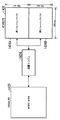
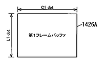
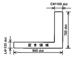
図9は、VRAM_FB1426の構成について説明するための説明図である。図9に示されるように、VRAM_FB1426は、描画エンジン1424によって描画される1フレーム分の画像をそれぞれ記憶する第1フレームバッファ1426A及び第2フレームバッファ1426Bを備えるダブルバッファ方式のメモリである。描画エンジン1424は、第1フレームバッファ1426A内の画像を液晶表示器5及びEL表示器6に出力している間には、次のフレームの画像を第2フレームバッファ1426Bに描画する。一方、第2フレームバッファ1426B内の画像を液晶表示器5及びEL表示器6に出力している間には、次のフレームの画像を第1フレームバッファ1426Aに描画する。このように、描画エンジン1424は、一方のフレームバッファから画像を出力している間に他方のフレームバッファに描画処理を行うことで、高いフレームレートで描画処理を行うことができる。
FIG. 9 is an explanatory diagram for describing a configuration of the VRAM_FB 1426. As illustrated in FIG. 9, the VRAM_FB 1426 is a double buffer type memory including a first frame buffer 1426 </ b> A and a second frame buffer 1426 </ b> B that each store an image for one frame drawn by the drawing engine 1424. The drawing engine 1424 draws an image of the next frame in the second frame buffer 1426B while outputting the image in the first frame buffer 1426A to the liquid crystal display 5 and the EL display 6. On the other hand, while the image in the second frame buffer 1426B is being output to the liquid crystal display 5 and the EL display 6, the image of the next frame is drawn in the first frame buffer 1426A. In this manner, the drawing engine 1424 can perform drawing processing at a high frame rate by performing drawing processing on the other frame buffer while outputting an image from one frame buffer.
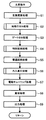
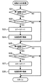
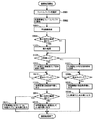
[遊技制御部100による主要動作]
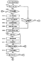
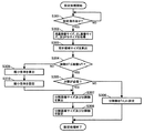
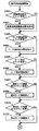
次に、遊技制御部100において行われる主要動作について説明する。図10は、遊技制御部100によって行われる主要動作の一例を示すフローチャートである。遊技制御部100は、電源投入時や電源断時等の特殊な場合を除く通常の動作時において、図10に示されている一連の処理を一定時間(例えば4ミリ秒)毎に繰り返し実行する。なお、図10以降のフローチャートに基づいて説明する遊技制御部100の処理は、ROM102に記憶されているプログラムに基づいてCPU101が発行する命令に従って行われる。
[Main operations by game control unit 100]
Next, main operations performed in the game control unit 100 will be described. FIG. 10 is a flowchart illustrating an example of main operations performed by the game control unit 100. The game control unit 100 repeatedly executes a series of processes shown in FIG. 10 at regular intervals (for example, 4 milliseconds) in a normal operation except for special cases such as when the power is turned on and when the power is turned off. . Note that the processing of the game control unit 100 described based on the flowcharts of FIG. 10 and subsequent figures is performed in accordance with instructions issued by the CPU 101 based on a program stored in the ROM 102.
乱数更新処理(ステップS1)では、遊技制御部100のCPU101は、大当たり乱数、図柄乱数、リーチ乱数、変動パターン乱数、及び普通図柄乱数の各種の乱数の更新を行う。ここで、大当たり乱数は、特別図柄抽選の当選(大当たり)又は落選(ハズレ)を決定するための乱数である。図柄乱数は、特別図柄抽選に当選した場合に、当たりの種類(長当たり、短当たり、高確率状態への移行の有無、時短遊技状態への移行の有無)を決定するための乱数である。リーチ乱数は、特別図柄抽選に落選した場合に、リーチ有りの演出を行うか或いはリーチ無しの演出を行うかを決定するための乱数である。変動パターン乱数は、特別図柄が変動表示される際の変動パターンを決定するための乱数である。普通図柄乱数は、普通図柄抽選の当選又は落選を決定するための乱数である。大当たり乱数、図柄乱数、リーチ乱数、変動パターン乱数、及び普通図柄乱数は、このステップS1の処理が行われる毎に「1」ずつ加算される。そして、各抽選が行われた時点の値がステップS2の始動口スイッチ(SW)処理やステップS3のゲートスイッチ(SW)処理で取得され、ステップS4の特別図柄処理やステップS5の普通図柄処理で使用される。なお、このステップS1の処理を行うカウンタにはループカウンタが使用されており、設定されている乱数の最大値に達した後は、再び「0」に戻る。
In the random number update process (step S1), the CPU 101 of the game control unit 100 updates various random numbers such as jackpot random numbers, symbol random numbers, reach random numbers, variation pattern random numbers, and normal symbol random numbers. Here, the jackpot random number is a random number for determining whether the special symbol lottery is won (big hit) or lost (losing). The symbol random number is a random number for determining a winning type (long hit, short hit, presence / absence of transition to a high probability state, presence / absence of transition to a short-time gaming state) when a special symbol lottery is won. The reach random number is a random number for determining whether to perform an effect with reach or an effect without reach when the special symbol lottery is lost. The variation pattern random number is a random number for determining a variation pattern when a special symbol is displayed in a variable manner. The normal symbol random number is a random number for determining whether the normal symbol lottery is won or lost. The jackpot random number, the design random number, the reach random number, the variation pattern random number, and the normal design random number are incremented by “1” every time the process of step S1 is performed. Then, the values at the time each lottery is performed are acquired by the start switch (SW) process in step S2 or the gate switch (SW) process in step S3, and in the special symbol process in step S4 or the normal symbol process in step S5. used. Note that a loop counter is used as the counter for performing the processing of step S1, and after reaching the set maximum value of the random number, it returns to “0” again.
始動口スイッチ(SW)処理(ステップS2)では、CPU101は、第1始動口スイッチ111及び第2始動口スイッチ112の状態を監視し、いずれかのスイッチから検出信号が出力された場合に、第1特別図柄抽選の保留数U1や第2特別図柄抽選の保留数U2に関する処理や乱数(大当たり乱数、図柄乱数、リーチ乱数、及び変動パターン乱数)を取得する処理等を実行する。この始動口スイッチ処理の詳細については、図11に基づいて後に詳述する。
In the start port switch (SW) process (step S2), the CPU 101 monitors the states of the first start port switch 111 and the second start port switch 112, and when a detection signal is output from either switch, A process related to the number U1 of the special symbol lottery U1 and the number U2 of the special symbol lottery reserved U2 and a process of acquiring random numbers (a jackpot random number, a symbol random number, a reach random number, and a variation pattern random number) are executed. Details of the start port switch process will be described later with reference to FIG.
ゲートスイッチ(SW)処理(ステップS3)では、CPU101は、ゲートスイッチ114の状態を監視し、遊技球がゲート25を通過してゲートスイッチ114から検出信号が出力された場合に、普通図柄抽選の保留数が上限値未満であるか否かを判断する。そして、保留数が上限値未満であると判断した場合に、ステップS5の普通図柄処理に使用される普通図柄乱数を取得する。
In the gate switch (SW) process (step S3), the CPU 101 monitors the state of the gate switch 114. When the game ball passes through the gate 25 and a detection signal is output from the gate switch 114, the normal symbol lottery is performed. It is determined whether the number of holds is less than the upper limit value. Then, when it is determined that the number of holds is less than the upper limit value, a normal symbol random number used for the normal symbol processing in step S5 is acquired.
特別図柄処理(ステップS4)では、CPU101は、特別図柄抽選を実行し、表示器4に特別図柄を変動表示してから特別図柄抽選の結果を示す特別図柄を停止表示するための処理を実行する。この特別図柄処理については、図12に基づいて後に詳述する。
In the special symbol process (step S4), the CPU 101 executes a special symbol lottery, displays the special symbol on the display 4 in a variable manner, and then executes a process for stopping and displaying the special symbol indicating the result of the special symbol lottery. . This special symbol process will be described later in detail with reference to FIG.
普通図柄処理(ステップS5)では、CPU101は、ステップS3のゲートスイッチ処理で取得された普通図柄乱数がその当選値と一致するか否かを判定する。そして、表示器4の普通図柄表示器45(図3参照)に普通図柄を変動表示させた後に判定結果を示す普通図柄を停止表示させる。
In the normal symbol process (step S5), the CPU 101 determines whether or not the normal symbol random number acquired in the gate switch process in step S3 matches the winning value. Then, after the normal symbol is variably displayed on the normal symbol display 45 (see FIG. 3) of the display device 4, the normal symbol indicating the determination result is stopped and displayed.
大入賞口処理(ステップS6)では、CPU101は、特別図柄抽選に当選した場合に、大入賞口制御部116を介して大入賞口23の開閉を制御する。
In the special prize opening process (step S6), the CPU 101 controls the opening / closing of the special prize opening 23 via the special prize opening control unit 116 when the special symbol lottery is won.
電動チューリップ処理(ステップS7)では、CPU101は、ステップS5の普通図柄処理において普通図柄乱数がその当選値と一致すると判定された場合に、電動チューリップ開閉部113を介して電動チューリップ27の一対の羽根部材を作動させる。電動チューリップ27が作動することによって第2始動口22へ遊技球が入賞可能な状態となり、第2始動口22に遊技球が入賞することで第2特別図柄抽選が始動する。
In the electric tulip processing (step S7), the CPU 101 determines that the normal symbol random number matches the winning value in the normal symbol processing in step S5, and the pair of blades of the electric tulip 27 via the electric tulip opening / closing unit 113. Actuate the member. When the electric tulip 27 is operated, a game ball can be awarded to the second start port 22, and when the game ball wins the second start port 22, the second special symbol lottery is started.
賞球処理(ステップS8)では、CPU101は、上述したように、遊技球の入賞個数の管理及び入賞に応じた賞球の払い出しを制御する。
In the prize ball process (step S8), as described above, the CPU 101 controls the number of game balls received and controls the payout of prize balls according to the prize.
出力処理(ステップS9)では、CPU101は、ステップS2の始動口スイッチ処理やステップS4の特別図柄処理等でRAM103にセットされた各種コマンドや演出に必要な情報を演出制御部130へ送る。また、ステップS8の賞球処理でRAM103にセットされた賞球の払い出しを指示するコマンドを払出制御部120へ送る。
In the output process (step S9), the CPU 101 sends various commands set in the RAM 103 and information necessary for the effect to the effect control unit 130 in the start port switch process in step S2 and the special symbol process in step S4. In addition, a command instructing the payout of the winning ball set in the RAM 103 in the winning ball processing in step S8 is sent to the payout control unit 120.
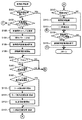
[遊技制御部100による始動口スイッチ処理]
図11は、図10のステップS2における始動口スイッチ処理の詳細フローチャートである。遊技制御部100のCPU101は、図11に示されるように、第1始動口スイッチ111からの検出信号の有無に基づいて、第1始動口21に遊技球が入賞して第1始動口スイッチ111がONになったか否かを判定する(ステップS21)。第1始動口スイッチ111がONになったと判定した場合(ステップS21:YES)、CPU101は、ROM102から第1特別図柄抽選の最大保留数Umax1(本実施形態では「4」)を読み出し、RAM103に記憶されている第1特別図柄抽選の保留数U1が上限値Umax1未満であるか否かを判定する(ステップS22)。
[Start-up switch processing by game control unit 100]
FIG. 11 is a detailed flowchart of the start port switch process in step S2 of FIG. As shown in FIG. 11, the CPU 101 of the game control unit 100 receives a game ball in the first start port 21 based on the presence or absence of a detection signal from the first start port switch 111, and the first start port switch 111. It is determined whether or not is turned on (step S21). If it is determined that the first start port switch 111 has been turned on (step S21: YES), the CPU 101 reads the maximum number Umax1 of the first special symbol lottery Umax1 (“4” in this embodiment) from the ROM 102, and stores it in the RAM 103 It is determined whether or not the stored number U1 of the first special symbol lottery is less than the upper limit value Umax1 (step S22).
CPU101は、保留数U1が最大保留数Umax1未満であると判定した場合(ステップS22:YES)、RAM103に記憶されている保留数U1の値を「1」加算した値に書き換える(ステップS23)。そして、CPU101は、ステップS23の処理によって保留した第1特別図柄抽選等に使用される乱数(大当たり乱数、図柄乱数、リーチ乱数、及び変動パターン乱数)を取得して、RAM103の所定領域に格納する(ステップS24)。
When the CPU 101 determines that the hold number U1 is less than the maximum hold number Umax1 (step S22: YES), the CPU 101 rewrites the value of the hold number U1 stored in the RAM 103 to a value obtained by adding “1” (step S23). Then, the CPU 101 obtains random numbers (big hit random numbers, symbol random numbers, reach random numbers, and variation pattern random numbers) used for the first special symbol lottery etc. reserved by the processing of step S23 and stores them in a predetermined area of the RAM 103. (Step S24).
第1始動口スイッチ111がOFFであると判定した場合(ステップS21:NO)、保留数U1が最大保留数Umax1と等しいと判定した場合(ステップS22:NO)、又はステップS24の処理を行った場合、CPU101は、第2始動口スイッチ112からの検出信号の有無に基づいて、第2始動口22に遊技球が入賞して第2始動口スイッチ112がONになったか否かを判定する(ステップS25)。第2始動口スイッチ112がONになったと判定した場合(ステップS25:YES)、CPU101は、ROM102から第2特別図柄抽選の最大保留数Umax2(本実施形態では「4」)を読み出し、RAM103に記憶されている第2特別図柄抽選の保留数U2が最大保留数Umax2未満であるか否かを判定する(ステップS26)。
When it is determined that the first start port switch 111 is OFF (step S21: NO), when it is determined that the hold number U1 is equal to the maximum hold number Umax1 (step S22: NO), or the process of step S24 is performed. In this case, the CPU 101 determines whether or not the game ball has won the second start port 22 and the second start port switch 112 is turned on based on the presence or absence of the detection signal from the second start port switch 112 ( Step S25). If it is determined that the second start port switch 112 has been turned on (step S25: YES), the CPU 101 reads the maximum number Umax2 of the second special symbol lottery Umax2 (“4” in this embodiment) from the ROM 102, and stores it in the RAM 103. It is determined whether the stored number U2 of the second special symbol lottery stored is less than the maximum number of reservations Umax2 (step S26).
CPU101は、保留数U2が最大保留数Umax2未満であると判定した場合(ステップS26:YES)、RAM103に記憶されている保留数U2の値を「1」加算した値に書き換える(ステップS27)。そして、CPU101は、ステップS27の処理によって保留した第2特別図柄抽選等に使用される乱数(大当たり乱数、図柄乱数、リーチ乱数、及び変動パターン乱数)を取得して、RAM103の所定領域に格納する(ステップS28)。
When the CPU 101 determines that the hold number U2 is less than the maximum hold number Umax2 (step S26: YES), the CPU 101 rewrites the value of the hold number U2 stored in the RAM 103 to a value obtained by adding “1” (step S27). Then, the CPU 101 obtains random numbers (big hit random numbers, symbol random numbers, reach random numbers, and variation pattern random numbers) used for the second special symbol lottery suspended by the processing of step S27 and stores them in a predetermined area of the RAM 103. (Step S28).
第2始動口スイッチ112がOFFであると判定した場合(ステップS25:NO)、保留数U2が最大保留数Umax2と等しいと判定した場合(ステップS26:NO)、又はステップS28の処理を行った場合、一連の処理が終了して図11のステップS3におけるゲートスイッチ処理へ処理が進められる。
When it is determined that the second start port switch 112 is OFF (step S25: NO), when it is determined that the hold number U2 is equal to the maximum hold number Umax2 (step S26: NO), or the process of step S28 is performed. In such a case, the series of processing ends, and the processing proceeds to the gate switch processing in step S3 of FIG.
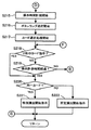
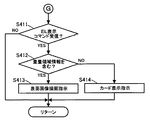
[遊技制御部100による特別図柄処理]
図12は、図10のステップS4における特別図柄処理の詳細フローチャートである。図12に示されるように、遊技制御部100のCPU101は、RAM103に記憶されている情報に基づいて、パチンコ遊技機1の現在の状態が大当たり中であるか否かを判定する(ステップS41)。大当たり中であるとCPU101が判定した場合(ステップS41:YES)、既に何らかの大当たりを表す特別図柄が選択されて停止表示されている状態であるため、特別図柄の変動表示を開始することなく特別図柄処理を終了し、図10のステップS5における普通図柄処理へ処理が進められる。
[Special symbol processing by game control unit 100]
FIG. 12 is a detailed flowchart of the special symbol process in step S4 of FIG. As shown in FIG. 12, the CPU 101 of the game control unit 100 determines whether or not the current state of the pachinko gaming machine 1 is a big hit based on the information stored in the RAM 103 (step S41). . When the CPU 101 determines that the jackpot is being hit (step S41: YES), since the special symbol representing some jackpot has already been selected and stopped, the special symbol is displayed without starting the special symbol variation display. The process ends, and the process proceeds to the normal symbol process in step S5 of FIG.
CPU101は、大当たり中ではないと判定した場合(ステップS41:NO)、表示器4の第1特別図柄表示器41又は第2特別図柄表示器42による特別図柄の変動表示中であるか否かを判定する(ステップS42)。CPU101は、特別図柄の変動表示中ではないと判定した場合(ステップS42:NO)、RAM103に記憶されている保留数U2が「1」以上であるか否かを判定する(ステップS43)。CPU101は、保留数U2が「1」以上であると判定した場合(ステップS43:YES)、RAM103に記憶されている保留数U2を「1」減算した値に書き換える(ステップS44)。
If the CPU 101 determines that the jackpot is not being won (step S41: NO), it is determined whether or not the special symbol change display is being performed by the first special symbol display 41 or the second special symbol display 42 of the display unit 4. Determination is made (step S42). When the CPU 101 determines that the special symbol variation display is not being performed (step S42: NO), the CPU 101 determines whether or not the holding number U2 stored in the RAM 103 is "1" or more (step S43). When the CPU 101 determines that the hold number U2 is “1” or more (step S43: YES), the CPU 101 rewrites the hold number U2 stored in the RAM 103 with a value obtained by subtracting “1” (step S44).
CPU101は、保留数U2が「1」以上ではない(第2特別図柄抽選が保留されていない)と判定した場合(ステップS43:NO)、RAM103に記憶されている保留数U1が「1」以上であるか否かを判定する(ステップS45)。CPU101は、保留数U1が「1」以上であると判定した場合(ステップS45:YES)、RAM103に記憶されている保留数U1を「1」減算した値に書き換える(ステップS46)。一方、保留数U1が「1」以上ではない(第1特別図柄抽選が保留されていない)とCPU101が判定した場合(ステップS45:NO)、特別図柄の変動表示を開始することなく特別図柄処理を終了し、図10のステップS5における普通図柄処理へ処理が進められる。
When the CPU 101 determines that the hold number U2 is not “1” or more (the second special symbol lottery is not held) (step S43: NO), the hold number U1 stored in the RAM 103 is “1” or more. It is determined whether or not (step S45). When the CPU 101 determines that the hold number U1 is “1” or more (step S45: YES), the CPU 101 rewrites the hold number U1 stored in the RAM 103 with a value obtained by subtracting “1” (step S46). On the other hand, when the CPU 101 determines that the holding number U1 is not equal to or greater than “1” (the first special symbol lottery is not held) (step S45: NO), the special symbol processing is started without starting the special symbol variable display. , And the process proceeds to the normal symbol process in step S5 of FIG.
CPU101は、ステップS44又はステップS46の処理を行った後、大当たり判定処理を実行する(ステップS47)。具体的には、ステップS44の処理に続いてステップS47の処理を実行する場合、CPU101は、ROM102に記憶されている大当たりの当選値をRAM103に読み出し、第2始動口22への遊技球の入賞を契機としてステップS28の処理(図11参照)で取得されてRAM103に格納された大当たり乱数がこの大当たりの当選値と一致するか否かに基づいて、第2特別図柄抽選の結果が大当たりであるかハズレであるかを判定する。一方、ステップS46の処理に続いてステップS47の処理を実行する場合、CPU101は、ROM102に記憶されている大当たりの当選値をRAM103に読み出し、第1始動口21への遊技球の入賞を契機としてステップS24の処理(図11参照)で取得されてRAM103に格納された大当たり乱数がこの大当たりの当選値と一致するか否かに基づいて、第1特別図柄抽選の結果が大当たりであるかハズレであるかを判定する。
After performing the process of step S44 or step S46, the CPU 101 executes a jackpot determination process (step S47). Specifically, when the process of step S47 is executed following the process of step S44, the CPU 101 reads the jackpot winning value stored in the ROM 102 into the RAM 103, and wins a game ball to the second starting port 22. The result of the second special symbol lottery is a jackpot based on whether or not the jackpot random number acquired in the process of step S28 (see FIG. 11) and stored in the RAM 103 matches the winning value of the jackpot. Or whether it is lost. On the other hand, when the process of step S47 is executed subsequent to the process of step S46, the CPU 101 reads the winning value stored in the ROM 102 into the RAM 103 and triggered by the winning of the game ball at the first start port 21. Whether or not the result of the first special symbol lottery is a jackpot based on whether or not the jackpot random number acquired in the process of step S24 (see FIG. 11) and stored in the RAM 103 matches the winning value of the jackpot. Determine if there is.
第1特別図柄抽選又は第2特別図柄抽選の結果が大当たりである場合、CPU101は、複数種の大当たりのそれぞれに割り当てられた図柄乱数をROM102から読み出す。そして、上述した当選値と一致するか否かの判定に使用した大当たり乱数と一緒に取得された図柄乱数が、複数種の大当たりのいずれの大当たりに割り当てられた図柄乱数と一致するか否かに応じて、大当たりの種類を判定する。そして、この大当たりの種類に応じた大当たり図柄を設定情報としてRAM103にセット(格納)する。一方、大当たりの判定結果がハズレである場合には、特別図柄抽選に落選したことを表すハズレ図柄を設定情報としてRAM103にセットする。
When the result of the first special symbol lottery or the second special symbol lottery is a jackpot, the CPU 101 reads the symbol random number assigned to each of the plurality of types of jackpots from the ROM 102. Whether the symbol random number acquired together with the jackpot random number used for determining whether or not it matches the winning value described above matches the symbol random number assigned to any one of the multiple types of jackpots In response, the jackpot type is determined. The jackpot symbol corresponding to the jackpot type is set (stored) in the RAM 103 as setting information. On the other hand, when the determination result of the jackpot is lost, a lost symbol indicating that the special symbol lottery is lost is set in the RAM 103 as setting information.
CPU101は、ステップS47の処理によって大当たり抽選の結果に応じた大当たり図柄又はハズレ図柄を設定情報としてセットした後に、変動パターン選択処理を実行する(ステップS48)。具体的には、ステップS47の大当たり判定処理で大当たりしたと判定した場合、大当たり用の変動パターンテーブルをROM102から読み出してRAM103にセットする。一方、ハズレと判定した場合、ROM102に記憶されているリーチ乱数をRAM103に読み出し、ステップS47の大当たり判定処理に使用した大当たり乱数及び図柄乱数と一緒に取得されたリーチ乱数が、このROM102から読み出したリーチ乱数と一致するか否かに基づいて、遊技者に対して大当たりを期待させるためのリーチ演出を行うか否かを判定する。そして、リーチ演出を行うと判定した場合にはリーチ用の変動パターンテーブルをROM102から読み出してRAM103にセットし、リーチ演出を行わないと判定した場合にはハズレ用の変動パターンテーブルをROM102から読み出してRAM103にセットする。ここで、変動パターンテーブルとは、予め用意されている複数の変動パターン(変動時間10秒、30秒、60秒、90秒など)と変動パターン乱数の乱数値とを対応付けたテーブルである。
The CPU 101 executes the variation pattern selection process after setting the jackpot symbol or the lost symbol corresponding to the result of the jackpot lottery as the setting information by the process of step S47 (step S48). Specifically, when it is determined that the big hit is determined in the big hit determination processing in step S47, the big hit variation pattern table is read from the ROM 102 and set in the RAM 103. On the other hand, if it is determined to be lost, the reach random number stored in the ROM 102 is read out to the RAM 103, and the reach random number acquired together with the jackpot random number and symbol random number used in the jackpot determination process in step S47 is read out from the ROM 102. Based on whether or not the reach random number matches, it is determined whether or not to perform a reach effect for causing the player to expect a big hit. When it is determined that the reach effect is to be performed, the reach variation pattern table is read from the ROM 102 and set in the RAM 103. When it is determined that the reach effect is not performed, the loss variation pattern table is read from the ROM 102. Set in the RAM 103. Here, the variation pattern table is a table in which a plurality of variation patterns (variation times 10 seconds, 30 seconds, 60 seconds, 90 seconds, etc.) prepared in advance are associated with random numbers of variation pattern random numbers.
次に、CPU101は、セットした変動パターンテーブルを参照して、ステップS47の大当たり判定処理に使用した大当たり乱数及び図柄乱数と一緒に取得された変動パターン乱数に対応する変動パターンを選択することによって特別図柄の変動パターン(変動時間)を決定する。このようにして選択された変動パターンは、設定情報としてRAM103にセットされる。
Next, the CPU 101 refers to the set variation pattern table and selects a variation pattern corresponding to the variation pattern random number acquired together with the jackpot random number and the symbol random number used in the jackpot determination process in step S47. The pattern variation pattern (variation time) is determined. The variation pattern selected in this way is set in the RAM 103 as setting information.
ステップS47の大当たり判定処理及びステップS48の変動パターン選択処理を行った後、CPU101は、大当たり判定処理を行ってセットした図柄の設定情報、変動パターン選択処理を行ってセットした変動パターンの設定情報、パチンコ遊技機1の遊技状態を示す遊技状態情報等を含む変動開始コマンドを生成してRAM103にセットする(ステップS49)。この変動開始コマンドは、後述するステップS50における特別図柄の変動表示を開始する際に、液晶表示器5による装飾図柄の変動表示の開始を指示するために用いられるコマンドであって、図10のステップS9における出力処理によって演出制御部130へ送信される。
After performing the jackpot determination process in step S47 and the variation pattern selection process in step S48, the CPU 101 sets the pattern setting information set by performing the jackpot determination process, the variation pattern setting information set by performing the variation pattern selection process, A change start command including game state information indicating the game state of the pachinko gaming machine 1 is generated and set in the RAM 103 (step S49). This variation start command is a command used to instruct the liquid crystal display 5 to start the variation display of decorative symbols when starting the variation display of special symbols in step S50 described later. It is transmitted to the effect control unit 130 by the output process in S9.
ステップS49の処理に続いて、CPU101は、ステップS49の処理でセットされた変動開始コマンドに含まれている設定情報に基づいて、表示器4の第1特別図柄表示器41又は第2特別図柄表示器42による特別図柄の変動表示を開始し(ステップS50)、変動時間の計測を開始する(ステップS51)。この変動時間を示す情報は、RAM103に一時的に格納される。なお、ステップS50における特別図柄の変動表示は、ステップS44の処理の後に行われる場合には第2特別図柄表示器42を用いて行われ、ステップS46の処理の後に行われる場合には第1特別図柄表示器41を用いて行われる。
Following the process of step S49, the CPU 101 displays the first special symbol display 41 or the second special symbol display of the display 4 based on the setting information included in the change start command set in the process of step S49. The special symbol variation display by the device 42 is started (step S50), and measurement of the variation time is started (step S51). Information indicating this variation time is temporarily stored in the RAM 103. Note that the special symbol variation display in step S50 is performed using the second special symbol display 42 when it is performed after the processing of step S44, and the first special symbol display when it is performed after the processing of step S46. This is performed using the symbol display 41.
CPU101は、ステップS51の処理によって変動時間の計測を開始した場合、又は特別図柄の変動表示中であると判定した場合(ステップS42:YES)、ステップS51における変動時間の計測開始からステップS48の変動パターン選択処理で設定された変動パターンに対応する変動時間が経過したか否かを判定する(ステップS52)。変動時間が経過していないとCPU101が判定した場合(ステップS52:NO)、特別図柄処理を終了して、図10のステップS5における普通図柄処理へ処理が進められる。
When the CPU 101 starts measuring the variation time by the process of step S51 or determines that the variation of the special symbol is being displayed (step S42: YES), the CPU 101 performs the variation of step S48 from the measurement start of the variation time in step S51. It is determined whether or not the variation time corresponding to the variation pattern set in the pattern selection process has elapsed (step S52). When the CPU 101 determines that the variation time has not elapsed (step S52: NO), the special symbol process is terminated, and the process proceeds to the normal symbol process in step S5 of FIG.
一方、CPU101は、変動時間が経過したと判定した場合(ステップS52:YES)、液晶表示器5による装飾図柄の変動表示の終了を指示する変動停止コマンドをRAM103にセットし(ステップS53)、ステップS50の処理で開始した第1特別図柄表示器41又は第2特別図柄表示器42による特別図柄の変動表示を終了する(ステップS54)。そして、CPU101は、計測した変動時間をリセットする(ステップS55)。なお、ステップS53の処理でセットされた変動停止コマンドは、図10のステップS9における出力処理によって演出制御部130へ送信される。
On the other hand, if the CPU 101 determines that the variation time has elapsed (step S52: YES), the CPU 101 sets a variation stop command for instructing the liquid crystal display 5 to end the variation display of the decorative symbol in the RAM 103 (step S53). The special symbol variation display by the first special symbol display 41 or the second special symbol display 42 started in the process of S50 is terminated (step S54). Then, the CPU 101 resets the measured variation time (step S55). Note that the change stop command set in the process of step S53 is transmitted to the effect control unit 130 by the output process in step S9 of FIG.
CPU101は、変動時間をリセットした後、ステップS47の大当たり判定処理の結果に応じてパチンコ遊技機1の遊技状態を変更したり、大当たりと判定した場合に大入賞口制御部116に大入賞口23の開閉制御を開始させるといった停止中処理を実行する(ステップS56)。具体的には、CPU101は、特別図柄抽選の結果が大当たりであるか否か、大当たりである場合にはその大当たりが確率変動を伴うか否か、その大当たりが時間短縮を伴うか否かを判定する。CPU101は、大当たりか否かの判定結果や、大当たりである場合における確率変動又は時間短縮を伴うか否かなどの判定結果に基づいてパチンコ遊技機1の遊技状態を判定する。そして、CPU101は、大当たりであると判定した場合に、演出制御部130に対して大当たりの開始を通知する情報及び大当たりの種類を示す情報を含む大当たり開始コマンドをRAM103にセットする。CPU101によってセットされた大当たり開始コマンドは、図10のステップS9における出力処理で演出制御部130へ送信される。
After resetting the variation time, the CPU 101 changes the gaming state of the pachinko gaming machine 1 according to the result of the jackpot determination process in step S47, or determines that the jackpot control unit 116 receives the jackpot 23 when it is determined to be a jackpot. A stop process such as starting the opening / closing control is executed (step S56). Specifically, the CPU 101 determines whether or not the result of the special symbol lottery is a jackpot, if the jackpot is a jackpot, whether the jackpot is accompanied by a probability change, and whether the jackpot is accompanied by a time reduction. To do. The CPU 101 determines the gaming state of the pachinko gaming machine 1 based on the determination result of whether or not it is a big hit, and the determination result such as whether or not probability fluctuation or time reduction is involved in the case of a big win. If the CPU 101 determines that the jackpot is successful, the CPU 101 sets a jackpot start command including information for notifying the presentation control unit 130 of the start of the jackpot and information indicating the type of jackpot in the RAM 103. The jackpot start command set by the CPU 101 is transmitted to the effect control unit 130 by the output process in step S9 of FIG.
[演出制御部130による演出制御処理]
以下、図面を参照しつつ、演出制御部130によって行われる演出制御処理について説明する。なお、以下で説明する演出制御部130で行われる処理は、ROM132に記憶されているプログラムに基づいてCPU131が発行する命令に従って行われる。
[Production control processing by production control unit 130]
Hereinafter, the effect control process performed by the effect control unit 130 will be described with reference to the drawings. In addition, the process performed in the production | presentation control part 130 demonstrated below is performed according to the command which CPU131 issues based on the program memorize | stored in ROM132.
図13は、演出制御部130の演出制御処理の一例を示すフローチャートである。演出制御部130のCPU131は、図13に示されるように、第1始動口21又は第2始動口22への遊技球の入賞を契機として実行される液晶画面50における装飾図柄を変動表示させる装飾図柄処理をする(ステップS100)。装飾図柄処理を終了すると、CPU131は、第1始動口21又は第2始動口22への遊技球の入賞を契機として実行される大当たり抽選において当選した場合の演出を決定する大当たり演出決定処理をする(ステップS200)。この大当たり演出決定処理では、大当たり遊技中に液晶画面50で再生されるアニメーションを遊技者に選択させるためのゲームが行われ、そのゲームの結果に応じて選択されたアニメーションが液晶画面50で再生される。ちなみに、このゲームに伴う演出は、液晶画面50及びEL画面60の2つの画面を用いて行われる。大当たり演出決定処理の詳細については、図21A及び図21Bに基づいて後に詳述する。
FIG. 13 is a flowchart illustrating an example of the effect control process of the effect control unit 130. As shown in FIG. 13, the CPU 131 of the effect control unit 130 variably displays a decoration pattern on the liquid crystal screen 50 that is executed when a game ball is won at the first starting port 21 or the second starting port 22. Symbol processing is performed (step S100). When the decorative symbol process is finished, the CPU 131 performs a jackpot effect determination process for determining an effect when winning in the jackpot lottery executed with the winning of the game ball at the first start port 21 or the second start port 22 as an opportunity. (Step S200). In the jackpot effect determination process, a game is performed for causing the player to select an animation to be played on the liquid crystal screen 50 during the jackpot game, and the animation selected according to the game result is played on the liquid crystal screen 50. The Incidentally, the effects accompanying this game are performed using two screens, a liquid crystal screen 50 and an EL screen 60. Details of the jackpot effect determination process will be described in detail later based on FIGS. 21A and 21B.
[演出制御部130による装飾図柄処理]
図14は、図13のステップS100における装飾図柄処理の一例を示す詳細フローチャートである。演出制御部130のCPU131は、図14に示されるように、液晶画面50における装飾図柄の変動表示を伴う演出(以下、装飾図柄変動演出と称する)を実行中であるか否かを、例えば、画像音響制御部140から取得した情報に基づいて判定する(ステップS101)。CPU131は、装飾図柄変動演出を実行中ではないと判定した場合(ステップS101:NO)、図12のステップS49の処理でセットされた変動開始コマンドを遊技制御部100から受信したか否かを判定する(ステップS102)。CPU131は、変動開始コマンドを受信していないと判定した場合(ステップS102:NO)、装飾図柄処理を終了して図13のステップS200へ処理を進める。
[Decoration processing by production control unit 130]
FIG. 14 is a detailed flowchart showing an example of the decorative symbol process in step S100 of FIG. As shown in FIG. 14, the CPU 131 of the effect control unit 130 determines whether or not an effect accompanied with a decorative symbol variation display on the liquid crystal screen 50 (hereinafter referred to as a decorative symbol variation effect) is being executed, for example. The determination is made based on the information acquired from the image sound control unit 140 (step S101). When the CPU 131 determines that the decorative symbol variation effect is not being executed (step S101: NO), the CPU 131 determines whether or not the variation start command set in the process of step S49 in FIG. 12 has been received from the game control unit 100. (Step S102). If the CPU 131 determines that the variation start command has not been received (step S102: NO), the decorative symbol process is terminated and the process proceeds to step S200 in FIG.
CPU131は、変動開始コマンドを受信したと判定した場合(ステップS102:YES)、その変動開始コマンドを解析し(ステップS103)、変動開始コマンドに含まれている変動パターンの設定情報(図柄、変動パターン等)に基づいて演出パターンを決定する(ステップS104)。そして、CPU131は、ステップS104で決定した演出パターンに従って、装飾図柄変動演出を開始する(ステップS105)。具体的には、CPU131は、ステップS104の処理で決定した演出パターンで装飾図柄変動演出の開始を指示する変動演出開始コマンドを画像音響制御部140へ送信する。
When the CPU 131 determines that the variation start command has been received (step S102: YES), the CPU 131 analyzes the variation start command (step S103), and sets the variation pattern setting information (symbol, variation pattern) included in the variation start command. Etc.) to determine the production pattern (step S104). Then, the CPU 131 starts the decorative symbol variation effect according to the effect pattern determined in step S104 (step S105). Specifically, CPU 131 transmits to image sound control unit 140 a change effect start command for instructing the start of the decoration symbol change effect with the effect pattern determined in step S104.
これに対して、画像音響制御部140のCPU141は、受信した変動演出開始コマンドに応じた装飾図柄変動演出の実行を指示する制御信号をVDP142へ出力する。VDP142の描画エンジン1424は、制御信号によって指示された装飾図柄変動演出を実行するのに必要な素材データを画像用ROM148から読み出してVRAM_RS1425に格納し、その素材データを基にVRAM_FB1426に画像を描画する。そして、VDP142の描画エンジン1424は、描画した画像を出力回路1427を介して液晶表示器5へ出力する。これにより、液晶画面50で装飾図柄変動演出が開始される。また、画像音響制御部140のCPU141は、受信した変動演出開始コマンドに応じた音響データをデータ処理して付図時の増幅器を介してスピーカ35に出力させる指示を示す制御信号を音響DSP143に出力する。これにより、液晶画面50上で行われる表示演出と連動した音による演出が行われる。また、ランプ制御部150のCPU151は、受信した変動演出開始コマンドに応じた動作パターン及び発光パターンをROM152から読み出して、可動役物7、盤ランプ8、及び枠ランプ36を作動させる。これにより、液晶画面50上で行われる表示演出と連動した光及び可動役物7による演出が行われる。
On the other hand, the CPU 141 of the image sound control unit 140 outputs a control signal for instructing execution of the decorative symbol variation effect according to the received variation effect start command to the VDP 142. The drawing engine 1424 of the VDP 142 reads material data necessary for executing the decorative symbol variation effect instructed by the control signal from the image ROM 148, stores it in the VRAM_RS 1425, and draws an image in the VRAM_FB 1426 based on the material data. . Then, the drawing engine 1424 of the VDP 142 outputs the drawn image to the liquid crystal display 5 via the output circuit 1427. Thereby, the decorative symbol variation effect is started on the liquid crystal screen 50. In addition, the CPU 141 of the image sound control unit 140 processes the sound data corresponding to the received variation effect start command and outputs a control signal indicating an instruction to output to the speaker 35 via the amplifier at the time of the drawing to the sound DSP 143. . Thereby, the effect by the sound interlocked with the display effect performed on the liquid crystal screen 50 is performed. In addition, the CPU 151 of the lamp control unit 150 reads out the operation pattern and the light emission pattern corresponding to the received variation effect start command from the ROM 152, and operates the movable accessory 7, the panel lamp 8, and the frame lamp 36. Thereby, the effect by the light and the movable accessory 7 interlocked with the display effect performed on the liquid crystal screen 50 is performed.
また、変動演出開始コマンドは、ランプ制御部150にも送信され、盤ランプ8、枠ランプ36及び可動役物7の発光や可動役物7の動作をステップS104で決定した演出パターンに従って制御する演出がランプ制御部150によって開始される。
The change effect start command is also transmitted to the lamp control unit 150, and the effect of controlling the light emission of the panel lamp 8, the frame lamp 36 and the movable accessory 7 and the operation of the movable accessory 7 according to the effect pattern determined in step S104. Is started by the lamp control unit 150.
CPU131は、装飾図柄を変動表示させると(ステップS105)、変動表示を開始してからの経過時間を示す変動時間の計測を開始する(ステップS106)。
When the CPU 131 displays the decorative symbol in a variable manner (step S105), the CPU 131 starts measuring a variable time indicating an elapsed time since the start of the variable display (step S106).
一方、CPU131は、装飾図柄の変動表示を伴う演出を実行中であると判定した場合(ステップS101:YES)又は変動時間の計測を開始した場合(ステップS106)、ステップS102の処理で受信したと判定した変動開始コマンドに含まれている設定情報に基づいて、今回の特別図柄抽選の結果がリーチ以上であるか否かを判定する(ステップS107)。
On the other hand, if the CPU 131 determines that an effect accompanied by a variation display of the decorative symbol is being executed (step S101: YES) or if measurement of the variation time is started (step S106), it is received in the process of step S102. Based on the setting information included in the determined change start command, it is determined whether or not the result of the current special symbol lottery is equal to or greater than reach (step S107).
CPU131は、今回の特別図柄抽選の結果がリーチ以上であると判定した場合(ステップS107:YES)、ステップS106で計測を開始した変動時間に基づいて、リーチ発展時間が経過したか否かを判定する(ステップS108)。具体的には、CPU131は、ステップS106で計測を開始した変動時間がリーチ発展時間以上となったか否かを判定する。ここで、リーチ発展時間とは、ステップS105で装飾図柄変動演出を開始してから、リーチ演出表示に発展するまでの時間である。また、リーチ演出表示とは、装飾図柄として変動表示されている3つの数字の中で、残りの2桁の数字が停止表示され、いずれか1桁の数字の変動表示が継続されている表示状態である。なお、リーチ発展時間は、ステップS102の処理で受信したと判定した変動開始コマンドに含まれている変動パターンの設定情報に基づいてステップS104でCPU131により演出パターンが決定されることにより設定される。
If the CPU 131 determines that the result of the special symbol lottery this time is greater than or equal to reach (step S107: YES), the CPU 131 determines whether or not the reach development time has elapsed based on the variation time started in step S106. (Step S108). Specifically, the CPU 131 determines whether or not the variation time at which measurement is started in step S106 is equal to or greater than the reach development time. Here, the reach development time is the time from the start of the decorative symbol variation effect in step S105 until the development of the reach effect display. In addition, the reach effect display is a display state in which the remaining two digits of the three numbers that are variably displayed as decorative designs are stopped and the variation display of any one digit is continued. It is. The reach development time is set by determining the effect pattern by the CPU 131 in step S104 based on the change pattern setting information included in the change start command determined to have been received in step S102.
CPU131は、リーチ発展時間が経過したと判定した場合(ステップS108:YES)、今回の特別図柄抽選の結果に応じて後述するステップS110の処理で開始するリーチ演出表示を開始済みか否かを、例えば、画像音響制御部140から取得した情報に基づいて判定する(ステップS109)。
When determining that the reach development time has elapsed (step S108: YES), the CPU 131 determines whether or not the reach effect display started in the process of step S110, which will be described later, has started according to the result of the special symbol lottery this time. For example, it determines based on the information acquired from the image sound control part 140 (step S109).
CPU131は、リーチ演出表示を開始済みでないと判定した場合(ステップS109:NO)、上述したリーチ演出表示を開始する(ステップS110)。具体的には、CPU131は、上述したリーチ演出表示を開始する指示を示すリーチ演出開始コマンドを画像音響制御部140に送信する。
When it is determined that the reach effect display has not been started (step S109: NO), the CPU 131 starts the reach effect display described above (step S110). Specifically, the CPU 131 transmits a reach effect start command indicating an instruction to start the reach effect display described above to the image sound control unit 140.
これに対して、画像音響制御部140のCPU141は、上述したリーチ演出表示及び裏返されたカード501〜505の液晶画面50の所定位置への表示を指示する制御信号をVDP142へ出力する。VDP142の描画エンジン1424は、制御信号によって表示するように指示された画像、すなわち、リーチ演出表示に必要な画像及び裏返されたカード501〜505の画像を示す画像データを画像用ROM148から読み出してVRAM_RS1425に格納し、その画像データを基にVRAM_FB1426に画像を描画して出力回路1427を介して液晶表示器5に出力する。これにより、上述したように1つの数字のみが変動表示されるリーチ演出表示と、液晶画面50における所定位置への裏返されたカード501〜505の表示が開始される。図15には、ステップS111の処理が行われて、裏返された5つのカード501〜505を示す画像が液晶画面50における所定位置にそれぞれ表示されている状態が示されている。
On the other hand, the CPU 141 of the image sound control unit 140 outputs to the VDP 142 a control signal instructing the above-described reach effect display and display on the liquid crystal screen 50 of the reversed cards 501 to 505. The drawing engine 1424 of the VDP 142 reads from the image ROM 148 image data indicating an image instructed to be displayed by a control signal, that is, an image necessary for reach effect display and an image of the reversed cards 501 to 505, and VRAM_RS 1425. The image is drawn on the VRAM_FB 1426 based on the image data and output to the liquid crystal display 5 through the output circuit 1427. Thereby, as described above, reach effect display in which only one number is variably displayed, and display of the reversed cards 501 to 505 to a predetermined position on the liquid crystal screen 50 are started. FIG. 15 shows a state in which the image of the five cards 501 to 505 turned upside down is displayed at predetermined positions on the liquid crystal screen 50 after the process of step S111 is performed.
CPU131は、液晶画面50にカード501〜505を表示させると、カード501〜505の液晶画面50における表示位置を、例えば画像音響制御部140から取得してRAM133に格納する(ステップS111)。
When the CPU 131 displays the cards 501 to 505 on the liquid crystal screen 50, the CPU 131 acquires the display positions of the cards 501 to 505 on the liquid crystal screen 50 from, for example, the image sound control unit 140 and stores them in the RAM 133 (step S111).
そして、CPU131は、EL表示器6のEL画面60を所定の移動パターンで移動させる指示を示す移動開始コマンドをランプ制御部150に送信してEL表示器6の移動を開始させる(ステップS112)。
Then, the CPU 131 transmits a movement start command indicating an instruction to move the EL screen 60 of the EL display 6 with a predetermined movement pattern to start the movement of the EL display 6 (step S112).
これに対して、ランプ制御部150のCPU151は、所定の移動パターンでEL表示器6のEL画面60が移動するように第1ステッピングモータ29及び第2ステッピングモータ30を制御する。図16には、待機位置から初期位置にEL画面60が配置された状態が示されている。EL画面60の移動パターンは、例えば、図16に破線の矢印で示すように液晶画面50に表示されたカードの上側(遊技盤2の前面側)を順番に通過しながら往復するような移動パターンである。
In contrast, the CPU 151 of the lamp control unit 150 controls the first stepping motor 29 and the second stepping motor 30 so that the EL screen 60 of the EL display 6 moves in a predetermined movement pattern. FIG. 16 shows a state where the EL screen 60 is arranged from the standby position to the initial position. The movement pattern of the EL screen 60 is, for example, a movement pattern that reciprocates while sequentially passing through the upper side of the card displayed on the liquid crystal screen 50 (the front side of the game board 2) as shown by the dashed arrows in FIG. It is.
CPU131は、EL画面60の移動を開始させた場合(ステップS112)又はリーチ演出表示が開始済みであると判断した場合(ステップS109:YES)、液晶画面50に対するEL画面60の位置を示す位置情報を、ランプ制御部150から取得してRAM133に格納する(ステップS113)。EL画面60の位置情報は、例えば、図17に示されるように、EL画面60の中心位置G1を液晶画面50における二次元の座標で示す情報である。そして、EL画面60の位置情報で示される中心位置G1は、例えば、ランプ制御部150のCPU151が、第1ステッピングモータ29及び第2ステッピングモータ30のそれぞれのステップ数に基づいて液晶画面50における二次元の座標として認識する。
If the CPU 131 starts moving the EL screen 60 (step S112) or determines that the reach effect display has been started (step S109: YES), the position information indicating the position of the EL screen 60 with respect to the liquid crystal screen 50 Is acquired from the lamp control unit 150 and stored in the RAM 133 (step S113). The position information of the EL screen 60 is information indicating the center position G1 of the EL screen 60 by two-dimensional coordinates on the liquid crystal screen 50, as shown in FIG. The central position G1 indicated by the position information on the EL screen 60 is, for example, determined by the CPU 151 of the lamp control unit 150 based on the number of steps of the first stepping motor 29 and the second stepping motor 30, respectively. Recognize as dimension coordinates.
位置判定手段として機能するCPU131は、液晶画面50に表示されたカードを遊技者がEL画面60を通して視認できるか否かを、EL画面60の位置情報とカード501〜505のそれぞれの位置情報とに基づいて判定する(ステップS115)。CPU131は、液晶画面50に表示されたカード501〜505を遊技者がEL画面60を通して視認できるか否かを判定するとき図17に示すEL画面60の表示領域及び図18に示すカードの表示領域に基づいて判定する。
The CPU 131 functioning as a position determination means determines whether or not the player can visually recognize the card displayed on the liquid crystal screen 50 through the EL screen 60 based on the position information on the EL screen 60 and the position information on each of the cards 501 to 505. Based on the determination (step S115). When the CPU 131 determines whether or not the player can visually recognize the cards 501 to 505 displayed on the liquid crystal screen 50 through the EL screen 60, the display area of the EL screen 60 shown in FIG. 17 and the display area of the card shown in FIG. Determine based on.
以下、図19A及び図19Bを参照しながら、CPU131が、液晶画面50に表示されたカードを遊技者がEL画面60を通して視認できるか否かを判定する処理を説明する。尚、図19A及び図19Bにおける点Oは、液晶画面50を構成する画素の位置を二次元のX−Y座標で示すときの原点である。また、図19A及び図19Bにそれぞれ示すX軸は水平方向12(図1参照)に沿った方向であり、Y軸は垂直方向11(図1参照)に沿った方向である。
Hereinafter, a process in which the CPU 131 determines whether or not the player can visually recognize the card displayed on the liquid crystal screen 50 through the EL screen 60 will be described with reference to FIGS. 19A and 19B. Note that the point O in FIGS. 19A and 19B is the origin when the positions of the pixels constituting the liquid crystal screen 50 are indicated by two-dimensional XY coordinates. 19A and 19B, the X axis is a direction along the horizontal direction 12 (see FIG. 1), and the Y axis is a direction along the vertical direction 11 (see FIG. 1).
CPU131は、液晶画面50に表示されたカードを遊技者がEL画面60を通して視認できるか否かを判定するとき、まず、透過領域を認識する。ここで、透過領域とは、何も表示されていないEL画面60を遊技者が遊技盤2の前方からみたときに通して視認できると考えられる液晶画面50上の領域である。具体的には、演出制御部130のROM132には、ランプ制御部150から取得した中心位置G1を基準として透過領域を図17に示すように四角形として規定するための所定の幅B1と所定の高さV1とが格納されている。CPU131は、透過領域を認識するとき、まず、ステップS113でRAM133に格納したEL画面60の中心位置G1とROM132に格納されている所定の幅B1を参照する。そして、CPU131は、参照した中心位置G1を基準とする幅B1に基づいて、図19Aに示すように、液晶画面50における透過領域の幅を規定するX座標TX1及びTX2を認識する。次に、CPU131は、ステップS113でRAM133に格納したEL画面60の中心位置G1とROM132に格納されている所定の高さV1とを参照する。そして、CPU131は、参照した中心位置G1を基準とする高さV1に基づいて、図19Aに示すように、液晶画面50における透過領域の高さを規定するY座標TY1及びTY2を認識する。CPU131は、TX1、TX2、TY1及びTY2をそれぞれ認識すると、液晶画面50の画素の中で、X座標がTX1からTX2の間に含まれ、Y座標がTY1からTY2の間に含まれる画素からなる領域をEL画面60の透過領域として認識する。
When determining whether or not the player can visually recognize the card displayed on the liquid crystal screen 50 through the EL screen 60, the CPU 131 first recognizes the transparent area. Here, the transmissive area is an area on the liquid crystal screen 50 that is considered to be visible when the player views the EL screen 60 on which nothing is displayed from the front of the game board 2. Specifically, the ROM 132 of the effect control unit 130 has a predetermined width B1 and a predetermined height for defining the transmission region as a quadrangle as shown in FIG. 17 with the center position G1 acquired from the lamp control unit 150 as a reference. V1 is stored. When recognizing the transmissive area, the CPU 131 first refers to the center position G1 of the EL screen 60 stored in the RAM 133 and the predetermined width B1 stored in the ROM 132 in step S113. Then, the CPU 131 recognizes the X coordinates TX1 and TX2 that define the width of the transmission region in the liquid crystal screen 50, as shown in FIG. 19A, based on the width B1 with the referenced center position G1 as a reference. Next, the CPU 131 refers to the center position G1 of the EL screen 60 stored in the RAM 133 in step S113 and the predetermined height V1 stored in the ROM 132. Then, the CPU 131 recognizes the Y coordinates TY1 and TY2 that define the height of the transmissive region in the liquid crystal screen 50, as shown in FIG. When the CPU 131 recognizes TX1, TX2, TY1, and TY2, each of the pixels on the liquid crystal screen 50 includes pixels whose X coordinate is included between TX1 and TX2 and whose Y coordinate is included between TY1 and TY2. The area is recognized as a transparent area of the EL screen 60.
次に、CPU131は、液晶画面50におけるカード501〜505のそれぞれの表示領域を認識する。ここでは、説明の便宜のため、CPU131が、液晶画面50におけるカード501の表示領域を認識する場合を一例として説明する。具体的には、演出制御部130のROM132には、画像音響制御部140から取得した中心位置G2を基準としてカード501の表示領域を図18に示すように四角形として規定するための所定の幅B2と所定の高さV2とが格納されている。CPU131は、カード501の表示領域を認識するとき、まず、ステップS111でRAM133に格納したカード501の表示領域の中心位置G2とROM132に格納されている所定の幅B2を参照する。そして、CPU131は、参照した中心位置G2を基準とする幅B2に基づいて、図19Aに示すように、液晶画面50におけるカード501の表示領域の幅を規定するX座標DX1及びDX2を認識する。次に、CPU131は、ステップS111でRAM133に格納したカード501の表示領域の中心位置G2とROM132に格納されている所定の高さV2とを参照する。そして、CPU131は、参照した中心位置G2を基準とする高さV2に基づいて、図19Aに示すように、液晶画面50におけるカード501の表示領域を規定するY座標DY1及びDY2を認識する。CPU131は、DX1、DX2、DY1及びDY2をそれぞれ認識すると、液晶画面50の画素の中で、X座標がDX1からDX2の間に含まれ、Y座標がDY1からDY2に含まれる画素からなる領域をカード501の表示領域として認識する。CPU131は、カード502〜505の表示領域についても同様に認識する。
Next, the CPU 131 recognizes the display areas of the cards 501 to 505 on the liquid crystal screen 50. Here, for convenience of explanation, a case where the CPU 131 recognizes the display area of the card 501 on the liquid crystal screen 50 will be described as an example. Specifically, the ROM 132 of the effect control unit 130 has a predetermined width B2 for defining the display area of the card 501 as a rectangle as shown in FIG. 18 with the center position G2 acquired from the image sound control unit 140 as a reference. And a predetermined height V2 are stored. When recognizing the display area of the card 501, the CPU 131 first refers to the center position G2 of the display area of the card 501 stored in the RAM 133 in step S111 and the predetermined width B2 stored in the ROM 132. Then, the CPU 131 recognizes the X coordinates DX1 and DX2 that define the width of the display area of the card 501 in the liquid crystal screen 50, based on the width B2 based on the referenced center position G2, as shown in FIG. 19A. Next, the CPU 131 refers to the center position G2 of the display area of the card 501 stored in the RAM 133 in step S111 and the predetermined height V2 stored in the ROM 132. Then, the CPU 131 recognizes the Y coordinates DY1 and DY2 that define the display area of the card 501 in the liquid crystal screen 50, as shown in FIG. 19A, based on the height V2 with the referenced center position G2 as a reference. When the CPU 131 recognizes DX1, DX2, DY1, and DY2, each of the pixels on the liquid crystal screen 50 includes an area that includes pixels whose X coordinate is included between DX1 and DX2 and whose Y coordinate is included between DY1 and DY2. It is recognized as the display area of the card 501. The CPU 131 recognizes the display areas of the cards 502 to 505 in the same manner.
CPU131は、透過領域とカード501〜505の表示領域とを認識すると、それぞれの領域に基づいて、液晶画面50に表示されたカード501〜505の少なくとも一部を遊技者がEL画面60を通して視認できるか否かを判定する。具体的には、CPU131は、図19Bに示すように、それぞれ認識した透過領域とカード501〜505の表示領域とを構成する画素の中で、X座標及びY座標がそれぞれ一致する画素からなる領域があるか否かを判定する。そして、CPU131は、X座標及びY座標がそれぞれ一致する画素からなる領域があると判定したとき、液晶画面50に裏返されて表示されたカードを遊技者がEL画面60を通して視認できると判定する。一方、CPU131は、X座標及びY座標がそれぞれ一致する画素からなる領域がないと判定したとき、液晶画面50に裏返されて表示されたカードを遊技者がEL画面60を通して視認できないと判定できる。
When the CPU 131 recognizes the transmissive area and the display areas of the cards 501 to 505, the player can visually recognize at least a part of the cards 501 to 505 displayed on the liquid crystal screen 50 through the EL screen 60 based on the respective areas. It is determined whether or not. Specifically, as shown in FIG. 19B, the CPU 131 is an area made up of pixels whose X coordinates and Y coordinates coincide with each other among the pixels constituting the recognized transparent areas and the display areas of the cards 501 to 505. It is determined whether or not there is. When the CPU 131 determines that there is an area composed of pixels having the same X coordinate and Y coordinate, the CPU 131 determines that the player can visually recognize the card displayed upside down on the liquid crystal screen 50 through the EL screen 60. On the other hand, when the CPU 131 determines that there is no region composed of pixels having the same X coordinate and Y coordinate, it can be determined that the player cannot visually recognize the card displayed upside down on the liquid crystal screen 50 through the EL screen 60.
CPU131は、液晶画面50に裏返されて表示されたカードが、EL画面60を通して遊技者から視認できると判定すると(ステップS115:YES)、上述した透過領域と表示領域とが重畳する重畳領域を認識する(ステップS116)。具体的には、CPU131は、図19Bに斜線で示すように、X座標及びY座標がそれぞれ一致するとステップS115で判定した画素からなる領域を重畳領域として認識する。
When the CPU 131 determines that the card displayed upside down on the liquid crystal screen 50 is visible from the player through the EL screen 60 (step S115: YES), the CPU 131 recognizes the overlapping region where the above-described transparent region and the display region overlap. (Step S116). Specifically, as indicated by hatching in FIG. 19B, the CPU 131 recognizes, as a superposed region, an area composed of pixels determined in step S115 when the X coordinate and the Y coordinate coincide with each other.
CPU131は、ステップS116の処理に続いて、EL画像の表示を指示するEL表示コマンドに重畳領域を構成する全ての画素のX座標及びY座標を示す重畳領域情報を含めて画像音響制御部140に送信し、EL画像を表示させる(ステップS117)。
Subsequent to the processing in step S116, the CPU 131 includes the EL display command for instructing the display of the EL image and includes the superimposition area information indicating the X coordinate and the Y coordinate of all the pixels constituting the superimposition area in the image acoustic control unit 140. Then, the EL image is displayed (step S117).
これに対して、画像音響制御部140のCPU141は、液晶画面50に表示されているカード501〜505の中で重畳領域に含まれる部分の表面を示す表面画像が、液晶画面50の重畳領域にEL画面60で重畳するように表示する指示を示す制御信号にCPU131から送信された重畳領域情報を含ませてVDP142へ出力する。
On the other hand, the CPU 141 of the image sound control unit 140 displays a surface image indicating the surface of the portion included in the overlapping area in the cards 501 to 505 displayed on the liquid crystal screen 50 in the overlapping area of the liquid crystal screen 50. The superimposition area information transmitted from the CPU 131 is included in a control signal indicating an instruction to be displayed so as to be superimposed on the EL screen 60 and output to the VDP 142.
これに対して、VDP142は、CPU141から出力される制御信号に含まれる重畳領域情報に基づいて、液晶画面50に表示されたカード501〜505の中で重畳領域に含まれるカードの部分の表面を示す表面画像を、EL画面60上で重畳する位置に表示する。具体的には、VDP142の描画エンジン1424が、CPU141から送信された重畳領域情報で示される全ての画素のX座標及びY座標に基づいて、液晶画面50に表示されているカード501〜505の画像の中で重畳領域に含まれるカードの部分を認識する。そして、描画エンジン1424は、認識したカードの部分の表面画像のデータを画像用ROM148から読み出してVRAM_RS1425に格納する。描画エンジン1424は、VRAM_RS1425に格納した画像データで示される表面画像が、液晶画面50の重畳領域に含まれるカードにEL画面60上で重畳するように表示され、他の部分には何も表示されない画像をEL画像として生成してVRAM_FB1426に描画する。VDP142の描画エンジン1424は、このようにEL画像をVRAM_FB1426に描画するとともに、ステップS110で開始したカード501〜505の表示も継続されるように、裏返されたカード501〜505もVRAM_FB1426に描画する。そして、VRAM_FB1426に描画されたEL画像は出力回路1427を介してEL表示器6に出力され、カード501〜505を示す画像は出力回路1427を介して液晶表示器5に出力される。
On the other hand, the VDP 142 determines the surface of the portion of the card included in the overlapping area among the cards 501 to 505 displayed on the liquid crystal screen 50 based on the overlapping area information included in the control signal output from the CPU 141. The surface image to be shown is displayed at a position to be superimposed on the EL screen 60. Specifically, the image of the cards 501 to 505 displayed on the liquid crystal screen 50 based on the X coordinate and the Y coordinate of all the pixels indicated by the drawing engine 1424 of the VDP 142 transmitted from the CPU 141. The card portion included in the overlapping area is recognized. The drawing engine 1424 reads out the surface image data of the recognized card portion from the image ROM 148 and stores it in the VRAM_RS 1425. The drawing engine 1424 displays the surface image indicated by the image data stored in the VRAM_RS 1425 so as to be superimposed on the EL screen 60 on the card included in the overlapping area of the liquid crystal screen 50, and nothing is displayed in other portions. An image is generated as an EL image and drawn on the VRAM_FB 1426. The drawing engine 1424 of the VDP 142 draws the EL image on the VRAM_FB 1426 as described above, and also draws the reversed cards 501 to 505 on the VRAM_FB 1426 so that the display of the cards 501 to 505 started in step S110 is continued. The EL image drawn on the VRAM_FB 1426 is output to the EL display 6 through the output circuit 1427, and the images showing the cards 501 to 505 are output to the liquid crystal display 5 through the output circuit 1427.
従って、図20A〜図20Eにそれぞれ一例として示すように、所定の移動パターンで移動するEL表示器6のEL画面60を通して視認可能なカードの表面が順番に表示される。図20A〜図20Eに示す例は、移動するEL画面60を遊技者に目で追わせることによって、「チャンス!」の文字を読ませ、リーチ演出における期待感を煽って興趣性を高められるEL画像を示している。
Therefore, as shown as an example in each of FIGS. 20A to 20E, the surface of the card that is visible through the EL screen 60 of the EL display 6 that moves in a predetermined movement pattern is displayed in order. In the example shown in FIGS. 20A to 20E, the player can read the letter “chance!” By following the moving EL screen 60 with the eyes, and can enhance the interest by raising the expectation in the reach production. An image is shown.
一方、CPU131は、視認可能でないと判定した場合(ステップS115:NO)又はEL表示コマンドを送信した場合(ステップS117)に、図11のステップS53の処理でセットされた変動停止コマンドを受信したか否かを判定する(ステップS118)。CPU131は、変動停止コマンドを受信したと判定した場合(ステップS118:YES)、装飾図柄の変動表示を伴う演出を終了する(ステップS119)。具体的には、CPU131は、ステップS105の処理で開始した液晶表示器5による装飾図柄の変動表示を終了して特別図柄抽選の結果を示す停止図柄を液晶表示器5に表示させ、EL表示器6を所定の待機位置で何も表示しない初期状態に初期化する指示を示す変動演出終了コマンドを画像音響制御部140に送信する。
On the other hand, if the CPU 131 determines that it is not visible (step S115: NO) or has transmitted an EL display command (step S117), has the CPU 131 received the change stop command set in the process of step S53 of FIG. It is determined whether or not (step S118). When it is determined that the variation stop command has been received (step S118: YES), the CPU 131 ends the effect accompanied by the variation display of the decorative symbol (step S119). Specifically, the CPU 131 terminates the decorative symbol variation display by the liquid crystal display 5 started in the process of step S105, displays a stop symbol indicating the result of the special symbol lottery on the liquid crystal display 5, and the EL display A variable effect end command indicating an instruction to initialize 6 to an initial state in which nothing is displayed at a predetermined standby position is transmitted to the image sound control unit 140.
CPU131は、変動演出終了コマンドを送信した場合(ステップS119)、変動停止コマンドを受信していないと判定した場合(ステップS118:NO)又は変動開始コマンドを受信していないと判定した場合(ステップS102)、図14の装飾図柄処理を終了して図13のステップS200へ処理を進める。
When the CPU 131 transmits a change effect end command (step S119), when it is determined that a change stop command is not received (step S118: NO), or when it is determined that a change start command is not received (step S102). ), The decorative design process of FIG. 14 is terminated, and the process proceeds to step S200 of FIG.
[演出制御部130による大当たり演出決定処理]
図21A〜図21Bは、図13のステップS200における大当たり演出決定処理の一例を示す詳細フローチャートである。CPU131は、図21Aに示されるように、大当たり演出を実行中であるか否かを、例えば、画像音響制御部140から取得した情報に基づいて判定する(ステップS201)。CPU131は、大当たり演出を実行中でないと判定した場合(ステップS201:NO)、図10のステップS9の処理によって遊技制御部100から送信される大当たり開始コマンドを受信したか否かを判定する(ステップS202)。大当たり開始コマンドを受信したと判定すると(ステップS202:YES)、CPU131は、裏返されたカード501〜505を液晶画面50における所定位置へ表示させる指示をしめすカード表示コマンドを画像音響制御部140に送信して、カードの表示を開始する(ステップS203)。
[Don't win effect determination process by effect control unit 130]
21A to 21B are detailed flowcharts showing an example of the jackpot presentation determination process in step S200 of FIG. As illustrated in FIG. 21A, the CPU 131 determines whether or not a jackpot effect is being executed based on, for example, information acquired from the image sound control unit 140 (step S <b> 201). When determining that the jackpot effect is not being executed (step S201: NO), the CPU 131 determines whether or not the jackpot start command transmitted from the game control unit 100 is received by the process of step S9 of FIG. S202). If it is determined that the jackpot start command has been received (step S202: YES), the CPU 131 transmits to the image sound control unit 140 a card display command for instructing to display the reversed cards 501 to 505 at predetermined positions on the liquid crystal screen 50. Then, the card display is started (step S203).
これに対して、画像音響制御部140のCPU141は、裏返されたカード501〜505を液晶画面50における所定位置への表示を指示する制御信号をVDP142へ出力する。VDP142の描画エンジン1424は、制御信号によって示される指示に従って裏返されたカード501〜505の画像を示す画像データを画像用ROM148から読み出してVRAM_RS1425に格納する。そして、描画エンジン1424は、VRAM_RS1425に格納した画像データを基にVRAM_FB1426に画像を描画して出力回路1427を介して液晶表示器5に出力する。これにより、液晶画面50における所定位置への裏返されたカード501〜505の表示(図15参照)が開始される。
On the other hand, the CPU 141 of the image sound control unit 140 outputs a control signal for instructing display of the reversed cards 501 to 505 to a predetermined position on the liquid crystal screen 50 to the VDP 142. The drawing engine 1424 of the VDP 142 reads out image data indicating the image of the cards 501 to 505 turned over according to the instruction indicated by the control signal from the image ROM 148 and stores it in the VRAM_RS 1425. The drawing engine 1424 draws an image on the VRAM_FB 1426 based on the image data stored in the VRAM_RS 1425 and outputs the image to the liquid crystal display 5 via the output circuit 1427. Thereby, the display of the reversed cards 501 to 505 to a predetermined position on the liquid crystal screen 50 (see FIG. 15) is started.
ステップS203の処理に続いて、CPU131は、上述したステップS111〜ステップS112と同様の処理をして、表示させたカード501〜505の表示位置を取得し(ステップS204)、EL画面60を所定の移動パターンにおける移動を開始させる(ステップS205)。EL画面60の移動を開始すると、CPU131は、大当たり演出の実行中においてEL画面60の移動を開始させてからの経過時間を示す移動時間の計測を開始する(ステップS206)。
Subsequent to the processing in step S203, the CPU 131 performs the same processing as in steps S111 to S112 described above to acquire the display positions of the displayed cards 501 to 505 (step S204), and displays the EL screen 60 on a predetermined basis. The movement in the movement pattern is started (step S205). When the movement of the EL screen 60 is started, the CPU 131 starts measuring the movement time indicating the elapsed time from the start of the movement of the EL screen 60 during the execution of the jackpot effect (step S206).
一方、CPU131は、大当たり演出を実行中であると判定した場合(ステップS201:YES)、後述するカード選択処理が実行済みであるか否かを判定する(ステップS207)。CPU131は、ステップS207でカード選択処理を実行済みであると判定した場合(ステップS207:YES)、大当たり演出決定処理を終了して図13のステップS100へ処理を戻す。
On the other hand, when determining that the jackpot effect is being executed (step S201: YES), the CPU 131 determines whether or not a card selection process to be described later has been executed (step S207). When CPU 131 determines in step S207 that the card selection process has been executed (step S207: YES), it ends the jackpot effect determination process and returns the process to step S100 in FIG.
CPU131は、移動時間の計測を開始した場合(ステップS206)又はカード選択処理が実行済みでないと判定した場合(ステップS207:NO)、図14のステップS113と同様にEL画面60の位置情報を取得してRAM133に格納する(ステップS208)。そして、CPU131は、図14のステップS115〜S117と同様の処理をして、液晶画面50に表示されたカード501〜505がEL画面60を通して遊技者から視認できるか否かを判定し(ステップS209)、視認できると判定した場合(ステップS209:YES)には、重畳領域を認識して(ステップS210)、画像音響制御部140にEL画像を表示させる(ステップS211)。
When the CPU 131 starts measuring the travel time (step S206) or determines that the card selection process has not been executed (step S207: NO), the CPU 131 acquires the position information of the EL screen 60 as in step S113 of FIG. And stored in the RAM 133 (step S208). Then, the CPU 131 determines whether or not the cards 501 to 505 displayed on the liquid crystal screen 50 are visible from the player through the EL screen 60 by performing the same processing as steps S115 to S117 in FIG. 14 (step S209). ) If it is determined that it can be visually recognized (step S209: YES), the superimposed region is recognized (step S210), and the EL image is displayed on the image sound control unit 140 (step S211).
ここで、大当たり演出決定処理において液晶画面50に裏返されて表示されるカード501〜505は、リーチ演出表示において図20A〜図20Eを参照して説明したようにカードの表面の文字を順番に表示したときに1つの単語を示すようなカードではない。大当たり演出決定処理において液晶画面50に裏返されて表示されるカード501〜505には、図22A〜図22Eを参照して後述で説明するように、同一の演出の名称(例えば、アニメーションのタイトル)が表面に描かれている2枚一組のカード(以下、同一カードと称する)が含まれる。このように、同一カードを少なくとも一組含む5枚の裏返したカード501〜505を液晶画面50に表示することにより、遊技者に神経衰弱ゲームを提供できる。
Here, the cards 501 to 505 displayed by being reversed on the liquid crystal screen 50 in the jackpot effect determination process sequentially display the characters on the surface of the card as described with reference to FIGS. 20A to 20E in the reach effect display. It is not a card that shows one word when you do. In cards 501 to 505 displayed on the liquid crystal screen 50 in the jackpot effect determination process, the name of the same effect (for example, the title of the animation) is described later with reference to FIGS. 22A to 22E. Includes a set of two cards (hereinafter referred to as the same card). In this way, by displaying the five inverted cards 501 to 505 including at least one set of the same cards on the liquid crystal screen 50, it is possible to provide the player with a nervous breakdown game.
そして、CPU131が、EL画面60を移動させながら、ステップS209〜ステップS211の処理を繰り返すことにより、後述するように遊技者が2枚のカードを指示するのに先立って、図22A〜図22Eにそれぞれ示すように、神経衰弱ゲームの解答がEL画面60の移動に伴って順番に表示される。
Then, the CPU 131 moves the EL screen 60 and repeats the processing from step S209 to step S211 so that, as will be described later, the player instructs two cards as shown in FIGS. 22A to 22E. As shown, the answers to the nervous breakdown game are displayed in order as the EL screen 60 moves.
また、CPU131が大当たり演出決定処理において画像音響制御部140に表示させるEL画像は、上述の説明から明らかなように同一カードの表面に同一の演出の名称を示す画像である。さらに、CPU131は、後述するように遊技者によって同一カードが指示されたか否かを判定する。従って、CPU131は、ステップS203において、カード表示コマンドを送信するときに、まずカード501〜505の中に少なくとも1組の同一カードが含まれるように、カード501〜505の表面にそれぞれ示す演出の名称を決定する。そして、CPU131は、決定したカード501〜505の表面にそれぞれ示す演出の名称を識別する情報をRAM133に格納する。CPU131は、ステップS203において、カード501〜505の表面にそれぞれ示す演出を識別する情報を格納した後、カード表示コマンドを送信する。
Further, the EL image that the CPU 131 displays on the image sound control unit 140 in the jackpot effect determination process is an image indicating the name of the same effect on the surface of the same card as is apparent from the above description. Further, the CPU 131 determines whether or not the same card is instructed by the player as will be described later. Therefore, when the CPU 131 transmits a card display command in step S203, first, the name of the effect shown on the surface of each of the cards 501 to 505 so that at least one set of the same cards is included in the cards 501 to 505. To decide. And CPU131 stores the information which identifies the name of the production | presentation shown on the surface of the determined cards 501-505 in RAM133, respectively. In step S203, the CPU 131 stores information for identifying the effects shown on the surfaces of the cards 501 to 505, and then transmits a card display command.
CPU131は、液晶画面50に表示されたカード501〜505がEL画面60を通して遊技者から視認できないと判定した場合(ステップS209:NO)又はEL画像を表示させた場合(ステップS211)、ステップS206の処理で計測を開始したEL画面60の移動時間が所定の移動許容時間を経過したか否かを判定する(ステップS212)。具体的には、CPU131は、計測している移動時間が移動許容時間以上であるか否かを判定する。CPU131は、計測している移動時間が移動許容時間以上である場合、移動時間が所定の移動許容時間を経過したと判定する。一方、CPU131は、計測している移動時間が移動許容時間以上でない場合、移動時間が所定の移動許容時間を経過していないと判定する。
If the CPU 131 determines that the cards 501 to 505 displayed on the liquid crystal screen 50 are not visible from the player through the EL screen 60 (step S209: NO) or displays an EL image (step S211), the CPU 131 proceeds to step S206. It is determined whether or not the movement time of the EL screen 60 that has started measurement in the process has passed a predetermined movement allowable time (step S212). Specifically, the CPU 131 determines whether or not the measured movement time is equal to or longer than the movement allowable time. When the measured movement time is equal to or longer than the movement allowable time, the CPU 131 determines that the movement time has passed the predetermined movement allowable time. On the other hand, when the measured movement time is not equal to or longer than the allowable movement time, the CPU 131 determines that the predetermined movement allowable time has not elapsed.
CPU131は、EL画面60の移動時間が移動許容時間を経過したと判定した場合(ステップS212:YES)、計測している移動時間をゼロにリセットすると共に、EL画面60の所定の待機位置への退避を指示するコマンドをランプ制御部150へ送信して、EL画面60の待機位置への退避を開始させる(ステップS213)。一方、CPU131は、EL画面60の移動時間が移動許容時間を経過していないと判定した場合(ステップS212:NO)、大当たり演出決定処理を終了して図13のステップS100へ処理を戻す。
When the CPU 131 determines that the movement time of the EL screen 60 has passed the allowable movement time (step S212: YES), the CPU 131 resets the measured movement time to zero and sets the EL screen 60 to a predetermined standby position. A command for instructing retraction is transmitted to the lamp control unit 150 to start retraction to the standby position of the EL screen 60 (step S213). On the other hand, when CPU 131 determines that the movement time of EL screen 60 has not passed the movement allowable time (step S212: NO), it ends the jackpot effect determination process and returns the process to step S100 in FIG.
ステップS213の処理に続いて、CPU131は、後述するカード選択処理で遊技者に対してカードの選択指示を許可する操作時間を計測中であるか否かを判定する(ステップS214)。CPU131は、操作時間を計測中でないと判定した場合(ステップS214:NO)、操作時間の計測を開始し(ステップS215)、ボタンランプ40の点灯を指示するコマンドをランプ制御部150へ送信してボタンランプ40の点灯を開始する(ステップS216)。
Subsequent to the process of step S213, the CPU 131 determines whether or not an operation time during which a card selection instruction is permitted to the player is being measured in a card selection process described later (step S214). When the CPU 131 determines that the operation time is not being measured (step S214: NO), the CPU 131 starts measuring the operation time (step S215), and transmits a command to turn on the button lamp 40 to the lamp control unit 150. The button lamp 40 is turned on (step S216).
CPU131は、ボタンランプ40を点灯させると(ステップS216)、カード選択処理を開始する(ステップS217)。ここで、カード選択処理とは、大当たり演出中において、液晶画面50に表示されているカードの中から裏返すカードを演出キー38の操作により遊技者に選択指示させるための処理である。カード選択処理では、カード501〜505の中から1枚ずつ合計で2枚のカードを遊技者に選択させ、裏返す指示をさせる。遊技者にカードを選択させるとき、CPU131は、ランプ制御部150から取得される周辺キーの操作情報に基づいて、遊技者によって選択されている選択カードをカード501〜505の中から認識する。CPU131は、選択カードを認識すると、認識した選択カードの強調表示を画像音響制御部140に指示する選択カード強調表示コマンドを送信する。
When the button lamp 40 is turned on (step S216), the CPU 131 starts a card selection process (step S217). Here, the card selection process is a process for instructing the player to select a card to be turned over from the cards displayed on the liquid crystal screen 50 by operating the effect key 38 during the jackpot effect. In the card selection process, the player is made to select a total of two cards one by one from the cards 501 to 505 and instruct to turn them over. When causing the player to select a card, the CPU 131 recognizes the selected card selected by the player from the cards 501 to 505 based on the peripheral key operation information acquired from the lamp control unit 150. When the CPU 131 recognizes the selected card, the CPU 131 transmits a selected card highlight command for instructing the image sound control unit 140 to highlight the recognized selected card.
これに対して、選択カード強調表示コマンドを受信した画像音響制御部140が選択カードを強調表示することにより、周辺キーの操作に応じてカードの縁を強調する枠が液晶画面50で左右に移動するように表示される。具体的には、画像音響制御部140のCPU141が、液晶画面50に裏面が表示されているカード501〜505の中から選択カード強調表示コマンドによって指示される選択カードを認識する。CPU141は、認識した選択カードの縁の強調表示を指示する制御信号をVDP142へ出力する。VDP142は、制御信号に基づいて認識した選択候補カードを強調表示する。具体的には、VDP142の描画エンジン1424が、カードの縁を強調する枠を示す選択カード強調画像のデータを画像用ROM148から読み出してVRAM_RS1425に格納する。描画エンジン1424は、遊技者によって選択されている選択候補カードの縁が強調表示されるように、所定の表示位置に表示中のカード501〜505の画像と共に選択カード強調画像をVRAM_FB1426に描画する。VRAM_FB1426に描画された選択カード強調画像は、出力回路1427を介して液晶表示器5に出力される。これにより、遊技者による周辺キーの操作に応じて選択されている選択カードを示す枠が液晶画面50で左右に移動する表示が実現される。
On the other hand, the image sound control unit 140 that has received the selected card emphasis display command highlights the selected card, so that the frame for emphasizing the edge of the card moves left and right on the liquid crystal screen 50 in accordance with the operation of the peripheral keys. Is displayed. Specifically, the CPU 141 of the image sound control unit 140 recognizes the selected card indicated by the selected card highlight display command from the cards 501 to 505 whose back side is displayed on the liquid crystal screen 50. The CPU 141 outputs to the VDP 142 a control signal that instructs the highlighted display of the selected card edge. The VDP 142 highlights the selection candidate card recognized based on the control signal. Specifically, the drawing engine 1424 of the VDP 142 reads out selected card emphasized image data indicating a frame for emphasizing the edge of the card from the image ROM 148 and stores it in the VRAM_RS 1425. The drawing engine 1424 draws the selected card emphasized image in the VRAM_FB 1426 together with the images of the cards 501 to 505 being displayed at the predetermined display position so that the edge of the selection candidate card selected by the player is highlighted. The selected card emphasized image drawn on the VRAM_FB 1426 is output to the liquid crystal display 5 via the output circuit 1427. Thereby, the display which the frame which shows the selection card selected according to operation of the peripheral key by a player moves to right and left on the liquid crystal screen 50 is implement | achieved.
CPU131は、ランプ制御部150から取得される中央キーの操作情報によって中央キーが押下されていることが示されている場合、裏返すカードの指示を受けたと判定する。裏返すカードの指示を受けると、CPU131は、裏返す指示を受けたカードの強調表示を画像音響制御部140に指示する。具体的には、CPU131は、中央キーが押下されたときの選択カードをカード501〜505の中から認識する。中央キーが押下されたときの選択カードは、裏返す指示を受けた指示カードとしてCPU131によって認識される。CPU131は、指示カードを認識すると、認識した指示カードを示す識別子をRAM133に格納する。指示カードの識別子を格納すると、CPU131は、認識した指示カードの強調表示を画像音響制御部140に指示する指示カード強調表示コマンドを送信する。
When the operation information of the center key acquired from the lamp control unit 150 indicates that the center key is pressed, the CPU 131 determines that an instruction for turning over the card has been received. When receiving the instruction for the card to be turned over, the CPU 131 instructs the image sound control unit 140 to highlight the card that has received the instruction to turn it over. Specifically, the CPU 131 recognizes the selected card from the cards 501 to 505 when the center key is pressed. The selected card when the center key is pressed is recognized by the CPU 131 as an instruction card that has received an instruction to turn it over. When the CPU 131 recognizes the instruction card, the CPU 131 stores an identifier indicating the recognized instruction card in the RAM 133. When the identifier of the instruction card is stored, the CPU 131 transmits an instruction card highlight display command for instructing the image sound control unit 140 to highlight the recognized instruction card.
これに対して、指示カード強調表示コマンドを受信した画像音響制御部140が指示カードを強調表示することにより、遊技者によって裏返すように指示された指示カードの縁を強調する枠が液晶画面50に表示される。指示カードの縁を強調する枠は、選択カードの縁を強調する枠とは異なる枠として液晶画面50に表示される。指示カードを強調する枠は、選択カードを強調する枠を表示する場合と同様に、画像音響制御部140のCPU141からVDP142の描画エンジン1424に出力された制御信号に応じてVRAM_FB1426に描画されることによって、液晶画面50に表示される。
On the other hand, the image sound control unit 140 that has received the instruction card emphasis display command highlights the instruction card, so that a frame for emphasizing the edge of the instruction card instructed to turn over by the player is displayed on the liquid crystal screen 50. Is displayed. The frame that emphasizes the edge of the instruction card is displayed on the liquid crystal screen 50 as a frame different from the frame that emphasizes the edge of the selected card. The frame for emphasizing the instruction card is drawn in the VRAM_FB 1426 in accordance with the control signal output from the CPU 141 of the image sound control unit 140 to the drawing engine 1424 of the VDP 142, as in the case of displaying the frame for emphasizing the selected card. Is displayed on the liquid crystal screen 50.
CPU131は、操作時間を計測中であると判定した場合(ステップS214:YES)又はカード選択処理を開始した場合(ステップS217)、RAM133を参照し、指示カードの識別子が2つ格納されているか否かに基づいて、カード選択処理において2枚のカードが指示されたか否かを判定する(ステップS218)。CPU131は、指示カードの識別子が2つ格納されている場合、カード選択処理において2枚のカードが遊技者によって選択されたと判定する。一方、CPU131は、指示カードの識別子が2つ格納されていない場合、カード選択処理において2枚のカードが選択されていないと判定する。
When the CPU 131 determines that the operation time is being measured (step S214: YES) or when the card selection process is started (step S217), the RAM 133 is referred to and whether or not two instruction card identifiers are stored. Whether or not two cards are instructed in the card selection process is determined (step S218). When two identifiers of the instruction card are stored, the CPU 131 determines that two cards have been selected by the player in the card selection process. On the other hand, when two identifiers of the instruction card are not stored, the CPU 131 determines that two cards are not selected in the card selection process.
CPU131は、2枚のカードが選択されていないと判定した場合(ステップS218:NO)、ステップS215で計測を開始した操作時間が所定の操作許容時間を経過したか否かを判定する(ステップS219)。具体的には、CPU131は、計測している操作時間が操作許容時間以上であるか否かを判定する。CPU131は、計測している操作時間が操作許容時間以上である場合は、操作時間が操作許容時間を経過したと判定し、計測している操作時間が操作許容時間以上でない場合は、操作時間が操作許容時間を経過していないと判定する。
When the CPU 131 determines that two cards are not selected (step S218: NO), the CPU 131 determines whether or not the operation time at which measurement is started in step S215 has passed a predetermined allowable operation time (step S219). ). Specifically, the CPU 131 determines whether or not the measured operation time is equal to or longer than the operation allowable time. When the measured operation time is equal to or longer than the allowable operation time, the CPU 131 determines that the operation time has passed the allowable operation time. When the measured operation time is not equal to or longer than the allowable operation time, the operation time is determined. It is determined that the allowable operation time has not elapsed.
CPU131は、2枚のカードが選択されたと判定した場合(ステップS218:YES)又は操作時間が操作許容時間を経過したと判定した場合(ステップS219:YES)、選択された2枚のカードが、表面に描かれている演出の名称が同一である同一カードであるか否かを判定する(ステップS220)。具体的には、CPU131は、RAM133に格納されている2つの指示カードの識別子にそれぞれ対応する演出の名称を示す識別子が一致するか否かを判定する。CPU131は、2つの指示カードの演出の名称を示す識別子が一致したとき、裏返す指示を受けた2枚のカードが同一カードであると判定し、2つの指示カードの演出の名称を示す識別子が一致しなかったときは、裏返す指示を受けた2枚のカードが同一カードでないと判定する。
When the CPU 131 determines that two cards have been selected (step S218: YES) or when the operation time has determined that the operation allowable time has passed (step S219: YES), the two selected cards are It is determined whether or not the name of the effect drawn on the surface is the same card (step S220). Specifically, CPU 131 determines whether or not the identifiers indicating the names of effects corresponding to the identifiers of the two instruction cards stored in RAM 133 match. When the identifiers indicating the names of the effects of the two instruction cards match, the CPU 131 determines that the two cards that have received the instruction to turn over are the same card, and the identifier indicating the effects of the effects of the two instruction cards is one. If not, it is determined that the two cards that are instructed to turn over are not the same card.
CPU131は、選択された2枚のカードが同一カードであると判定した場合(ステップS220:YES)、指示された2枚の同一カードのいずれかの演出の名称を示す識別子をRAM131を参照することによって認識し、認識した演出を特別演出として開始する指示を画像音響制御部140及びランプ制御部150に与える(ステップS221)。
When the CPU 131 determines that the two selected cards are the same card (step S220: YES), the RAM 131 refers to the RAM 131 for an identifier indicating the name of any one of the designated two identical cards. And gives an instruction to start the recognized effect as a special effect to the image sound control unit 140 and the lamp control unit 150 (step S221).
一方、CPU131は、選択された2枚のカードが同一カードでないと判定した場合(ステップS220:NO)、同一カードでないカードが指示された場合における所定の演出の中からランダムに決定した演出の開始を指示する所定演出開始コマンドを画像音響制御部140及びランプ制御部150に送信する(ステップS222)。
On the other hand, when it is determined that the two selected cards are not the same card (step S220: NO), the CPU 131 starts an effect determined at random from predetermined effects when a card that is not the same card is designated. Is transmitted to the image sound control unit 140 and the lamp control unit 150 (step S222).
ここで、CPU131によって開始を指示される演出はアニメーションの再生である。従って、CPU131によって演出の開始を指示されると、画像音響制御部140のCPU141は指示された演出に対応するアニメーションの再生を指示する制御信号をVDP142に出力する。画像音響制御部140によって再生されるアニメーションは、例えば、画像用ROM148にMPEG2方式で符号化されたデータとして格納されている。従って、アニメーションの再生を指示する制御信号が出力されると、VDP142の描画エンジン1424は、制御信号で示されるアニメーションのデータを画像用ROM148から読み出してデコーダ1422に復号させる。復号されたアニメーションデータに含まれる映像データは、VRAM_RS1425に格納され、描画エンジン1424によってVRAM_FB1426に描画され、出力回路1427を介して液晶表示器5に出力される。また、復号されたアニメーションデータに含まれる音響データは、音響DSP143に出力され、必要なデータ処理が行われる。データ処理が行われた音響データは、液晶画面50に表示されるアニメーションと同期するように音響DSP143から不図示のスピーカ35に出力される。
Here, the effect instructed to start by the CPU 131 is reproduction of an animation. Therefore, when the CPU 131 is instructed to start the production, the CPU 141 of the image sound control unit 140 outputs a control signal instructing the reproduction of the animation corresponding to the designated production to the VDP 142. The animation reproduced by the image sound control unit 140 is stored in the image ROM 148 as data encoded by the MPEG2 method, for example. Accordingly, when a control signal instructing reproduction of the animation is output, the drawing engine 1424 of the VDP 142 reads out the animation data indicated by the control signal from the image ROM 148 and causes the decoder 1422 to decode it. Video data included in the decoded animation data is stored in the VRAM_RS 1425, drawn on the VRAM_FB 1426 by the drawing engine 1424, and output to the liquid crystal display 5 through the output circuit 1427. Also, the sound data included in the decoded animation data is output to the sound DSP 143, and necessary data processing is performed. The acoustic data subjected to the data processing is output from the acoustic DSP 143 to the speaker 35 (not shown) so as to be synchronized with the animation displayed on the liquid crystal screen 50.
CPU131は、ステップS215で計測を開始した操作時間が操作許容時間を経過していないと判定した場合(ステップS219:NO)、同一カードが指示された場合の演出の開始指示をした場合(ステップS221)又は同一カードが指示されていない場合の演出の開始指示をした場合(ステップS222)、大当たり演出決定処理を終了して図13のステップS100へ処理を戻す。
When the CPU 131 determines that the operation time at which the measurement is started in step S215 has not passed the operation allowable time (step S219: NO), the CPU 131 instructs the start of the effect when the same card is instructed (step S221). ) Or when an instruction to start an effect when the same card is not specified (step S222), the jackpot effect determination process is terminated and the process returns to step S100 in FIG.
このように、大当たり演出決定処理では、液晶画面50に表示されたカード501〜505の上(遊技盤2の前面側)を所定の移動パターンでEL画面60を移動させながら、EL画面60を通して遊技者に視認可能なカードの表面を示す画像がEL画面60に重畳するように表示させる処理を移動時間が移動許容時間を経過するまで続ける。その後、操作時間が操作許容時間を経過するまでに裏返す2枚のカードを遊技者に指示させて、同一カードが指示されたときには、同一カードの表面に示された名称の演出が行われる。一方、指示された2枚のカードが同一カードでなかった場合には、同一カードが選択されていない場合における名称の演出が行われる。
In this way, in the jackpot effect determination process, the game is played through the EL screen 60 while moving the EL screen 60 in a predetermined movement pattern on the cards 501 to 505 displayed on the liquid crystal screen 50 (the front side of the game board 2). The process of displaying an image showing the surface of the card visible to the user so as to be superimposed on the EL screen 60 is continued until the movement time has passed the movement allowable time. After that, the player is instructed to turn over two cards until the operation time has passed the allowable operation time, and when the same card is instructed, an effect of the name shown on the surface of the same card is performed. On the other hand, when the designated two cards are not the same card, the name is rendered when the same card is not selected.
ここで、例えば、同一カードが選択されなかった場合には実行されない特別な演出の名称を、2枚のカードの表面に表示すれば、同一カードを選択できた遊技者にのみ特別な演出を体験させることができる。さらに、特別な演出は、同一カードを選択できた場合にのみ実行されるので、移動しながら神経衰弱ゲームの解答を表示するEL画面60に確実に遊技者の注意を引いて興趣性を向上させられる。
Here, for example, if the name of a special effect that is not executed if the same card is not selected is displayed on the surface of the two cards, only a player who can select the same card will experience the special effect. Can be made. Furthermore, since the special performance is executed only when the same card can be selected, the player's attention is surely drawn on the EL screen 60 that displays the answers of the nervous breakdown game while moving, and the interest is improved. It is done.
尚、上述の説明では、操作時間が操作許容時間を経過するまでに2枚のカードが指示されなかった場合、すなわち、カードが1枚も指示されなかった場合或いは1枚だけカードが指示された場合にも、ステップS222において、同一カードが選択されていない場合における名称の演出が行われる。
In the above description, when two cards are not instructed before the operation time has passed the allowable operation time, that is, when no cards are instructed or only one card is instructed. Even in this case, in step S222, the name is rendered when the same card is not selected.
また、上述の説明では、EL画面60を通して視認できる液晶画面50に表示された全てのカードについて、裏返したカードの表面をEL画像として表示する場合を一例として説明した。しかしながら、例えば、図23A〜図23Eに示すように、液晶画面50に表示されたカード501〜505の中で所定のカードのみについてEL画面60を通して視認できると判定されたときにその表面をEL画像として表示するようにしてもよい。図23A〜図23Eに示す例では、カード501、カード503及びカード505の3枚のカードについてのみ、それらの表面をEL画像として表示する場合を示している。このように、所定のカードの表面をEL画像として表示することにより、遊技者により興味を持たせることができる。例えば、図23A〜図23Eに示すようにEL画像を表示すれば、全てのカードを裏返すと「あたりだよ」と表示されるのかもしれないという遊技者の想像を煽ることができる。
Further, in the above description, the case where the surface of the inverted card is displayed as an EL image is described as an example for all the cards displayed on the liquid crystal screen 50 that can be viewed through the EL screen 60. However, for example, as shown in FIGS. 23A to 23E, when it is determined that only a predetermined card among the cards 501 to 505 displayed on the liquid crystal screen 50 can be viewed through the EL screen 60, the surface is displayed as an EL image. May be displayed. In the example illustrated in FIGS. 23A to 23E, only the three cards of the card 501, the card 503, and the card 505 are displayed on their surfaces as EL images. Thus, by displaying the surface of a predetermined card as an EL image, the player can be more interested. For example, if an EL image is displayed as shown in FIGS. 23A to 23E, it is possible to make a player's imagination that when all the cards are turned over, it may be displayed as “It's OK”.
ところで、第1フレームバッファ1426A及び第2フレームバッファ1426Bは、本実施形態においては、いずれも垂直方向11に720ドット、水平方向12に960ドットの画素データを格納可能なメモリ領域を有している(図26A参照)。これに対して、液晶表示器5の液晶画面50に表示される画像(以下「液晶画像」と呼ぶ)は、垂直方向11に600ドット、水平方向12に800ドットの画素データから構成されている(図26A参照)。このため、EL画面60には画像を表示せずに液晶画面50にのみ画像を表示する場合には、何ら問題なく描画処理を行うことができる。しかしながら、EL画面60に表示されるEL画像が垂直方向11に240ドット、水平方向12に320ドットの画素データから構成されており(図26C参照)、液晶画像及びEL画像を並べて描画した場合に垂直方向11又は水平方向12の画素数が第1フレームバッファ1426Aに格納可能な画素データの画素数を超えるため、そのままでは、第1フレームバッファ1426Aに液晶画像及びEL画像を一緒に描画することは不可能である。これは、第2フレームバッファ1426Bに液晶画像及びEL画像を描画する場合についても同様である。そこで、本実施形態に係るVDP142は、第1フレームバッファ1426Aに液晶画像を描画した後にできる空き領域(図26B参照)にEL画像を複数の領域に分割した状態で描画することによって、第1フレームバッファ1426A(又は第2フレームバッファ1426B)に液晶画像及びEL画像を一緒に描画することを可能にしている。以下、このような描画処理を実現するためのパチンコ遊技機1の動作について詳細に説明する。なお、以下の説明では、第1フレームバッファ1426Aを使用して描画処理が行われる場合を例に説明するが、第2フレームバッファ1426Bを使用して描画処理を行う場合にも同様の処理が行われる。
Incidentally, in the present embodiment, each of the first frame buffer 1426A and the second frame buffer 1426B has a memory area that can store pixel data of 720 dots in the vertical direction 11 and 960 dots in the horizontal direction 12. (See FIG. 26A). In contrast, an image displayed on the liquid crystal screen 50 of the liquid crystal display 5 (hereinafter referred to as “liquid crystal image”) is composed of pixel data of 600 dots in the vertical direction 11 and 800 dots in the horizontal direction 12. (See FIG. 26A). For this reason, when an image is displayed only on the liquid crystal screen 50 without displaying an image on the EL screen 60, the drawing process can be performed without any problem. However, when the EL image displayed on the EL screen 60 is composed of pixel data of 240 dots in the vertical direction 11 and 320 dots in the horizontal direction 12 (see FIG. 26C), the liquid crystal image and the EL image are drawn side by side. Since the number of pixels in the vertical direction 11 or the horizontal direction 12 exceeds the number of pixels of pixel data that can be stored in the first frame buffer 1426A, it is not possible to draw a liquid crystal image and an EL image together in the first frame buffer 1426A. Impossible. The same applies to the case where a liquid crystal image and an EL image are drawn in the second frame buffer 1426B. Therefore, the VDP 142 according to the present embodiment draws the EL image in a state where the EL image is divided into a plurality of areas in a free area (see FIG. 26B) that is created after the liquid crystal image is drawn in the first frame buffer 1426A. The liquid crystal image and the EL image can be drawn together in the buffer 1426A (or the second frame buffer 1426B). Hereinafter, the operation of the pachinko gaming machine 1 for realizing such drawing processing will be described in detail. In the following description, the case where the drawing process is performed using the first frame buffer 1426A will be described as an example, but the same process is performed when the drawing process is performed using the second frame buffer 1426B. Is called.
[画像音響制御部140による分割画像サイズ及び分割数の設定]
第1フレームバッファ1426A及び第2フレームバッファ1426Bは、液晶画像が描画された場合に、描画処理に使用されていない空き領域が生じる(図25D参照)。EL画像は、この空き領域に描画されるが、空き領域にそのまま描画できない場合には複数の領域に分割された分割画像として空き領域に描画される。EL画像を分割画像として描画する処理は、予め設定された分割画像サイズSS及び分割数SNに基づいて行われる。
[Setting of divided image size and number of divisions by image acoustic control unit 140]
In the first frame buffer 1426A and the second frame buffer 1426B, when a liquid crystal image is drawn, an empty area that is not used for the drawing process is generated (see FIG. 25D). The EL image is drawn in this empty area, but if it cannot be drawn as it is in the empty area, it is drawn in the empty area as a divided image divided into a plurality of areas. The process of drawing the EL image as a divided image is performed based on a preset divided image size SS and the number of divisions SN.
以下、図24〜図26Cを参照しつつ、分割画像サイズSS及び分割数SNを設定する処理について説明する。ここで、図24は、画像音響制御部140によって行われる設定処理の一例を示すフローチャートである。図25A〜図25Dは、液晶画像サイズ、EL画像サイズ、フレームバッファサイズ、及び空き領域のサイズについて説明するための説明図である。図26A〜図26Cは、画像音響制御部140によって行われる設定処理について説明するための説明図である。なお、図24以降のフローチャートに基づいて説明する画像音響制御部140で行われる処理は、制御用ROM144(図8参照)に記憶されているプログラムに基づいてCPU141が発行する命令に従って行われる。
Hereinafter, processing for setting the divided image size SS and the number of divisions SN will be described with reference to FIGS. 24 to 26C. Here, FIG. 24 is a flowchart illustrating an example of a setting process performed by the image sound control unit 140. 25A to 25D are explanatory diagrams for explaining the liquid crystal image size, the EL image size, the frame buffer size, and the size of the empty area. 26A to 26C are explanatory diagrams for describing the setting process performed by the image sound control unit 140. Note that the processing performed by the image sound control unit 140 described based on the flowcharts of FIG. 24 and the subsequent steps is performed according to a command issued by the CPU 141 based on a program stored in the control ROM 144 (see FIG. 8).
例えばパチンコ遊技機1の電源が投入されたときや、液晶表示器5を用いた1画面表示から液晶表示器5及びEL表示器6を用いた2画面表示に切り換えられるとき等に、分割画像サイズSS及び分割数SNの設定処理を指示する設定指示コマンドが演出制御部130から画像音響制御部140へ送信される。これに対して、画像音響制御部140のCPU141は、設定指示コマンドを受信したか否かを判定する(ステップS201)。設定指示コマンドを受信していないとCPU141が判定した場合(ステップS201:NO)、待機状態となる。
For example, when the power of the pachinko gaming machine 1 is turned on, or when switching from a one-screen display using the liquid crystal display 5 to a two-screen display using the liquid crystal display 5 and the EL display 6, the divided image size A setting instruction command for instructing setting processing of the SS and the number of divisions SN is transmitted from the effect control unit 130 to the image sound control unit 140. On the other hand, the CPU 141 of the image sound control unit 140 determines whether or not a setting instruction command has been received (step S201). When the CPU 141 determines that a setting instruction command has not been received (step S201: NO), a standby state is entered.
CPU141は、設定指示コマンドを受信したと判定した場合(ステップS301:YES)、液晶画像サイズ、EL画像サイズ、及びフレームバッファ(FB)サイズを取得する(ステップS302)。具体的には、VDP142から第1フレームバッファ1426A及び第2フレームバッファ1426Bのフレームバッファサイズを取得してRAM145に格納すると共に、液晶画面50の画面解像度及びEL画面60の画面解像度を液晶画像サイズ及びEL画像サイズとしてVDP142を介して液晶表示器5及びEL表示器6から取得してRAM145に格納する。ここで、フレームバッファサイズは、図25Aに示されるように、第1フレームバッファ1426A(或いは第2フレームバッファ1426B)に格納可能な画素データの垂直方向11の画素数L1及び水平方向12の画素数C1を示す情報であり、本実施形態では720×960(垂直画素数L1×水平画素数C1)である(図26A参照)。液晶画像サイズは、図25Bに示されるように、液晶画像を構成する画素データの垂直方向11の画素数L2及び水平方向12の画素数C2を示す情報であり、液晶画面50の画面解像度と等しく、本実施形態では600×800(垂直画素数L2×水平画素数C2)である(図26A参照)。EL画像サイズは、図25Cに示されるように、EL画像を構成する画素データの垂直方向11の画素数L3及び水平方向12の画素数C3を示す情報であり、EL画面60の画面解像度と等しく、本実施形態では240×320(垂直画素数L3×水平画素数C3)である(図26C参照)。
When it is determined that the setting instruction command has been received (step S301: YES), the CPU 141 acquires the liquid crystal image size, the EL image size, and the frame buffer (FB) size (step S302). Specifically, the frame buffer sizes of the first frame buffer 1426A and the second frame buffer 1426B are acquired from the VDP 142 and stored in the RAM 145, and the screen resolution of the liquid crystal screen 50 and the screen resolution of the EL screen 60 are set to the liquid crystal image size and The EL image size is acquired from the liquid crystal display 5 and the EL display 6 via the VDP 142 and stored in the RAM 145. Here, as shown in FIG. 25A, the frame buffer size is the number of pixels L1 in the vertical direction 11 and the number of pixels in the horizontal direction 12 of the pixel data that can be stored in the first frame buffer 1426A (or the second frame buffer 1426B). This is information indicating C1, which is 720 × 960 (vertical pixel number L1 × horizontal pixel number C1) in this embodiment (see FIG. 26A). As shown in FIG. 25B, the liquid crystal image size is information indicating the number of pixels L2 in the vertical direction 11 and the number of pixels C2 in the horizontal direction 12 of the pixel data constituting the liquid crystal image, and is equal to the screen resolution of the liquid crystal screen 50. In this embodiment, it is 600 × 800 (vertical pixel number L2 × horizontal pixel number C2) (see FIG. 26A). The EL image size is information indicating the number of pixels L3 in the vertical direction 11 and the number of pixels C3 in the horizontal direction 12 of the pixel data constituting the EL image, as shown in FIG. 25C, and is equal to the screen resolution of the EL screen 60. In this embodiment, 240 × 320 (the number of vertical pixels L3 × the number of horizontal pixels C3) (see FIG. 26C).
次に、CPU141は、取得した液晶画像サイズ、及びフレームバッファサイズに基づいて、第1フレームバッファ1426Aに液晶画像を描画した後に生じる空き領域のサイズを算出する(ステップS303)。具体的には、以下の演算式を用いて、空き領域に描画可能な画素データの最低垂直画素数L4(図25D参照)、及び最低水平画素数C4(図25D参照)を算出する。
最低垂直画素数L4=垂直画素数L1−垂直画素数L2
最低水平画素数C4=水平画素数C1−水平画素数C2
本実施形態では、図26Aに示されるように、垂直画素数L1が「720」であり、垂直画素数L2が「600」であるため、最低垂直画素数L4として「120」が算出され、水平画素数C1が「960」であり、水平画素数C2が「800」であるため、最低水平画素数C4として「160」が算出される(図26B参照)。
Next, based on the acquired liquid crystal image size and the frame buffer size, the CPU 141 calculates the size of the empty area that is generated after drawing the liquid crystal image in the first frame buffer 1426A (step S303). Specifically, the minimum vertical pixel number L4 (see FIG. 25D) and the minimum horizontal pixel number C4 (see FIG. 25D) of the pixel data that can be drawn in the empty area are calculated using the following arithmetic expressions.
Minimum vertical pixel number L4 = vertical pixel number L1-vertical pixel number L2
Minimum horizontal pixel number C4 = horizontal pixel number C1−horizontal pixel number C2
In this embodiment, as shown in FIG. 26A, since the vertical pixel number L1 is “720” and the vertical pixel number L2 is “600”, “120” is calculated as the minimum vertical pixel number L4, and the horizontal Since the pixel number C1 is “960” and the horizontal pixel number C2 is “800”, “160” is calculated as the minimum horizontal pixel number C4 (see FIG. 26B).
続いて、CPU141は、以下の演算式を用いて、EL画像を構成する画素データの総数ST、及び空き領域に描画可能な画素データの総数VTを算出し、総数STが総数VT未満か否かを判定する(ステップS304)。
総数ST=垂直画素数L3×水平画素数C3
総数VT=垂直画素数L4×水平画素数C1+水平画素数C4×(垂直画素数L1−垂直画素数L4)
ここで、垂直画素数L3は、EL画像を構成する画素データの垂直方向11の画素数であり、水平画素数C3は、EL画像を構成する画素データの水平方向12の画素数である。総数ST及び総数VTを算出すると、CPU141は、総数STが総数VTよりも小さいか否かを判定する。総数STが総数VT未満であれば、EL画像をそのまま或いは分割して第1フレームバッファ1426Aに描画することができると判断することができる。一方、総数STが総数VTよりも大きければ、EL画像を分割したとしてもそのままでは第1フレームバッファ1426Aに描画することはできないと判断することができる。
Subsequently, the CPU 141 calculates the total number ST of pixel data constituting the EL image and the total number VT of pixel data that can be drawn in the empty area using the following arithmetic expression, and determines whether the total number ST is less than the total number VT. Is determined (step S304).
Total number ST = vertical pixel number L3 × horizontal pixel number C3
Total number VT = vertical pixel number L4 × horizontal pixel number C1 + horizontal pixel number C4 × (vertical pixel number L1−vertical pixel number L4)
Here, the vertical pixel number L3 is the number of pixels in the vertical direction 11 of the pixel data constituting the EL image, and the horizontal pixel number C3 is the number of pixels in the horizontal direction 12 of the pixel data constituting the EL image. After calculating the total number ST and the total number VT, the CPU 141 determines whether or not the total number ST is smaller than the total number VT. If the total number ST is less than the total number VT, it can be determined that the EL image can be drawn in the first frame buffer 1426A as it is or divided. On the other hand, if the total number ST is larger than the total number VT, it can be determined that even if the EL image is divided, it cannot be drawn in the first frame buffer 1426A as it is.
分割判定手段として機能するCPU141は、総数STが総数VT未満であると判定した場合(ステップS304:YES)、EL画像を空き領域に描画するためにEL画像を分割する必要があるか否かを判定する(ステップS305)。具体的には、サブ画像を構成する画素データの垂直画素数L3(図25C参照)が空き領域の最低垂直画素数L4(図25D参照)よりも小さいか、又はEL画像を構成する画素データの水平画素数C3(図25C参照)が空き領域の最低水平画素数C4(図25D参照)よりも小さいかの少なくとも一方の条件を満たしているか否かを判定する。ここで、垂直画素数L3が最低垂直画素数L4よりも小さいか、又は水平画素数C3が最低水平画素数C4よりも小さければ、EL画像を分割することなく空き領域に描画することが可能であると判定することができる。一方、垂直画素数L3が最低垂直画素数L4よりも大きく且つ水平画素数C3が最低水平画素数C4よりも大きい場合、EL画像を空き領域にそのまま描画できないので、EL画像を分割して描画する必要があると判定することができる。このように、CPU141は、空き領域のサイズ及びEL画像サイズに基づいて、EL画像の分割の必要性を判定する。
When determining that the total number ST is less than the total number VT (step S304: YES), the CPU 141 functioning as the division determination unit determines whether or not the EL image needs to be divided in order to draw the EL image in the empty area. Determination is made (step S305). Specifically, the number of vertical pixels L3 (see FIG. 25C) of the pixel data constituting the sub-image is smaller than the minimum number of vertical pixels L4 (see FIG. 25D) of the empty area, or the pixel data constituting the EL image. It is determined whether or not the horizontal pixel number C3 (see FIG. 25C) satisfies at least one of the conditions that the minimum number of horizontal pixels C4 in the empty area (see FIG. 25D) is satisfied. Here, if the number of vertical pixels L3 is smaller than the minimum number of vertical pixels L4 or the number of horizontal pixels C3 is smaller than the minimum number of horizontal pixels C4, it is possible to draw the EL image without dividing it. It can be determined that there is. On the other hand, when the vertical pixel number L3 is larger than the minimum vertical pixel number L4 and the horizontal pixel number C3 is larger than the minimum horizontal pixel number C4, the EL image cannot be drawn as it is in the empty area, so the EL image is divided and drawn. It can be determined that it is necessary. As described above, the CPU 141 determines the necessity of dividing the EL image based on the size of the empty area and the EL image size.
CPU141は、分割が不要であると判定した場合(ステップS305:NO)、分割数SNを「0」に設定する(ステップS306)。ここで、分割数SNは、空き領域に描画される分割画像の数を示す情報である。言い換えれば、分割数SNは、EL画像を構成する分割画像の数を示す情報である。このステップS306で設定された分割数SNは、設定情報としてRAM145に格納される。この設定情報は、VDP142へ出力される制御信号に含まれて、VDP142へと送られる。後に詳述するが、分割数SNが「0」に設定された場合、空き領域には分割画像が描画されず、EL画像がそのまま描画されることになる。
When the CPU 141 determines that the division is unnecessary (step S305: NO), the CPU 141 sets the division number SN to “0” (step S306). Here, the division number SN is information indicating the number of divided images drawn in the empty area. In other words, the division number SN is information indicating the number of divided images constituting the EL image. The division number SN set in step S306 is stored in the RAM 145 as setting information. This setting information is included in the control signal output to the VDP 142 and sent to the VDP 142. As will be described in detail later, when the division number SN is set to “0”, the divided image is not drawn in the empty area, and the EL image is drawn as it is.
算出手段として機能するCPU141は、分割が必要であると判定した場合(ステップS305:YES)、空き領域サイズ及びEL画像サイズに基づいて、分割画像サイズSS及び分割数SNを算出する(ステップS307)。ここで、分割画像サイズSSは、EL画像が分割数SNで示される個数の分割画像に分割された場合に、1個の分割画像のサイズ(垂直画素数及び水平画素数)を示す情報である。ステップS307では、以下の演算式を用いて、分割画像サイズSS(分割画像の垂直画素数SSLと分割画像の水平画素数SSC)及び分割数SNを算出する。
分割画像の垂直画素数SSL=最低垂直画素数L4
分割画像の水平画素数SSC=最低水平画素数C4
分割数SN=(垂直画素数L3/最低垂直画素数L4)×(水平画素数C3/最低水平画素数C4)
図26B及び図26Cに示されるように、本実施形態では、最低垂直画素数L4として「120」が算出され、最低水平画素数C4として「160」が算出される。このため、ここでの分割画像サイズSSは、120×160(垂直画素数SSL×水平画素数SSC)となる。また、分割数SNは、(240/120)×(320/160)により「4」が算出される。
When the CPU 141 functioning as a calculation unit determines that the division is necessary (step S305: YES), the CPU 141 calculates the divided image size SS and the division number SN based on the free area size and the EL image size (step S307). . Here, the divided image size SS is information indicating the size (number of vertical pixels and number of horizontal pixels) of one divided image when the EL image is divided into the number of divided images indicated by the number of divisions SN. . In step S307, the divided image size SS (the number of vertical pixels SSL of the divided image and the number of horizontal pixels SSC of the divided image) and the number of division SN are calculated using the following arithmetic expressions.
The number of vertical pixels of the divided image SSL = the minimum number of vertical pixels L4
The number of horizontal pixels SSC of the divided image = the minimum number of horizontal pixels C4
Number of divisions SN = (vertical pixel number L3 / minimum vertical pixel number L4) × (horizontal pixel number C3 / minimum horizontal pixel number C4)
As shown in FIGS. 26B and 26C, in this embodiment, “120” is calculated as the minimum vertical pixel number L4, and “160” is calculated as the minimum horizontal pixel number C4. Therefore, the divided image size SS here is 120 × 160 (vertical pixel number SSL × horizontal pixel number SSC). The division number SN is calculated as “4” by (240/120) × (320/160).
CPU141は、分割画像サイズSS及び分割数SNを算出した後、算出した分割画像サイズSS及び分割数SNを設定情報としてRAM145に格納する(ステップS308)。この設定情報は、VDP142へ出力される制御信号に含まれて、VDP142へと送られる。なお、ステップS308の設定処理に代えてステップS306の設定処理が行われた場合には、EL画像を分割する必要がないので分割画像サイズSSは算出されず、設定情報として、分割数SNが「0」であることを示す情報のみがVDP142へ送られる。
After calculating the divided image size SS and the division number SN, the CPU 141 stores the calculated divided image size SS and the division number SN in the RAM 145 as setting information (step S308). This setting information is included in the control signal output to the VDP 142 and sent to the VDP 142. When the setting process in step S306 is performed instead of the setting process in step S308, the divided image size SS is not calculated because it is not necessary to divide the EL image. Only information indicating “0” is sent to the VDP 142.
ここで、分割画像サイズSS及び分割数SNを変化させた場合の分割画像サイズSSと空き領域サイズとの関係について図26Cに基づいて説明する。垂直画素数L3が「240」であり水平画素数C3が「320」であるEL画像に対して、仮に分割数SNが「0」に設定された場合(ステップS306の処理が行われた場合)、図26B及び図26Cから明らかなように、垂直画素数L3が最低垂直画素数L4を超え且つ水平画素数C3が最低水平画素数C4を超えているので、第1フレームバッファ1426Aの空き領域にEL画像をそのまま描画することはできない。
Here, the relationship between the divided image size SS and the free area size when the divided image size SS and the number of divisions SN are changed will be described with reference to FIG. 26C. When the division number SN is set to “0” for the EL image having the vertical pixel number L3 of “240” and the horizontal pixel number C3 of “320” (when the process of step S306 is performed). As apparent from FIGS. 26B and 26C, since the number of vertical pixels L3 exceeds the minimum number of vertical pixels L4 and the number of horizontal pixels C3 exceeds the minimum number of horizontal pixels C4, the free space in the first frame buffer 1426A An EL image cannot be drawn as it is.
また、仮に分割数SNが「2」に設定された場合、EL画像を垂直画素数が「240」で水平画素数が「160」である2個の分割画像として空き領域に描画する第1の方法と、EL画像を垂直画素数が「120」で水平画素数が「320」である2個の分割画像として空き領域に描画する第2の方法とが考えられる(図26Cの真ん中の図を参照)。しかしながら、第1の方法でEL画像を描画することを考えた場合、空き領域内の垂直方向11に延びる領域(図26B参照)に2個の分割画像を描画することは可能であるが、空き領域内の水平方向12に延びる領域に分割画像を描画することはできない。なぜなら、分割画像の垂直画素数「240」が、空き領域の最低垂直画素数L4(=120)を超えているからである。また、第2の方法でEL画像を描画することを考えた場合、空き領域内の水平方向12に延びる領域(図26B参照)に2個の分割画像を描画することは可能であるが、空き領域内の垂直方向11に延びる領域に2個の分割画像を描画することはできない。なぜなら、分割画像の水平画素数「320」が、空き領域の最低水平画素数C4(=160)を超えているからである。このように、本実施形態で例示したEL画像を分割画像として空き領域に描画する際に分割数SNを「2」に設定すると、分割画像を描画する位置によっては、分割画像を空き領域に描画できないケースが生じ得る。
Further, if the division number SN is set to “2”, the EL image is drawn in the empty area as two divided images having the vertical pixel number “240” and the horizontal pixel number “160”. And a second method of drawing an EL image in a vacant area as two divided images having a vertical pixel count of “120” and a horizontal pixel count of “320” (see the middle diagram in FIG. 26C). reference). However, when drawing an EL image by the first method, it is possible to draw two divided images in an area (see FIG. 26B) extending in the vertical direction 11 in the empty area. A divided image cannot be drawn in a region extending in the horizontal direction 12 in the region. This is because the number of vertical pixels “240” of the divided image exceeds the minimum number of vertical pixels L4 (= 120) in the empty area. Further, when considering the EL image to be drawn by the second method, it is possible to draw two divided images in an area (see FIG. 26B) extending in the horizontal direction 12 in the empty area. Two divided images cannot be drawn in a region extending in the vertical direction 11 in the region. This is because the horizontal pixel number “320” of the divided image exceeds the minimum horizontal pixel number C4 (= 160) of the empty area. As described above, when the number of divisions SN is set to “2” when the EL image exemplified in this embodiment is drawn as a divided image in the empty area, the divided image is drawn in the empty area depending on the position where the divided image is drawn. Cases that cannot be done may occur.
これに対して、上述のように分割数SNが「4」に設定された場合、図26B及び図26Cの右側の図から明らかなように、垂直画素数SSLが空き領域の最低垂直画素数L4と同じ「120」に設定され、且つ水平画素数SSCが空き領域の最低水平画素数C4と同じ「160」に設定される。そして、この分割画像サイズSSの分割画像が空き領域に4個描画されることになる。この場合、各分割画像は、空き領域内の垂直方向11に延びる領域と水平方向12に延びる領域とのいずれにも描画可能である。従って、分割数SNが「2」に設定された場合とは異なり、分割画像を描画する位置によって空き領域に分割画像を描画できないケースが生じることはない。このように、分割数SN及び分割画像サイズSSは、分割画像をどのような配列で空き領域に描画したとしても確実に空き領域に収まるように、適切な値に設定される。
On the other hand, when the division number SN is set to “4” as described above, the vertical pixel number SSL is the minimum vertical pixel number L4 in the empty area, as is apparent from the diagrams on the right side of FIGS. 26B and 26C. And the horizontal pixel number SSC is set to “160” which is the same as the minimum horizontal pixel number C4 of the empty area. Then, four divided images of this divided image size SS are drawn in the empty area. In this case, each divided image can be drawn in either the area extending in the vertical direction 11 or the area extending in the horizontal direction 12 in the empty area. Therefore, unlike the case where the division number SN is set to “2”, there is no case where the divided image cannot be drawn in the empty area depending on the position where the divided image is drawn. As described above, the number of divisions SN and the divided image size SS are set to appropriate values so that the divided images can be surely fit in the empty area regardless of the arrangement of the divided images drawn in the empty area.
一方、上記ステップS304において総数STが総数VTよりも大きいとCPU141が判定した場合(ステップS304:NO)、たとえEL画像を分割したとしても、EL画像を構成する全ての画素データを空き領域に描画することは不可能である。このため、CPU141は、総数STが総数VTよりも大きいと判定した場合(ステップS304:NO)、縮小倍率を算出して(ステップS309)、算出した縮小倍率を設定情報としてRAM145に格納する(ステップS310)。そして、ステップS307,S308へ処理が進められて、分割画像サイズSS及び分割数SNが設定される。
On the other hand, if the CPU 141 determines in step S304 that the total number ST is larger than the total number VT (step S304: NO), even if the EL image is divided, all the pixel data constituting the EL image is drawn in the empty area. It is impossible to do. Therefore, if the CPU 141 determines that the total number ST is larger than the total number VT (step S304: NO), the CPU 141 calculates a reduction ratio (step S309), and stores the calculated reduction ratio in the RAM 145 as setting information (step S309). S310). Then, the process proceeds to steps S307 and S308, and the divided image size SS and the division number SN are set.
ここで、縮小倍率の設定方法について説明する。例えばステップS309で縮小倍率が「0.5」に設定された場合、垂直画素数L3が「240」であり水平画素数C3が「320」であるEL画像(図26Cの左側の図を参照)が、垂直画素数L3が「120」(=240×0.5)であり水平画素数C3が「160」(=320×0.5)であるEL画像として、ステップS307,S308の処理が行われる。この場合、描画処理に際して、VRAM_RS1425上で垂直方向11及び水平方向12の画素数を1/2にしたEL画像が生成されて、そのEL画像が、分割画像サイズSS及び分割数SNに基づく分割画像として第1フレームバッファ1426Aの空き領域に描画されることになる。そして、これらの分割画像は、垂直方向11及び水平方向12の画素数を2倍にするスケーリング処理(拡大処理)が描画エンジン1424によって行われてからEL表示器6へ出力される。これにより、分割したとしても空き領域に描画できないEL画像を空き領域に描画することが可能になる。従って、空き領域サイズに対して画面解像度が大きい画像表示器を備えるパチンコ遊技機において、従来の描画処理ではその画像表示器に画像を表示することができないという問題を、分割画像サイズSS及び分割数SNに加えて縮小倍率を設定することで解決することができる。
Here, a method for setting the reduction ratio will be described. For example, when the reduction ratio is set to “0.5” in step S309, an EL image in which the vertical pixel number L3 is “240” and the horizontal pixel number C3 is “320” (see the left diagram in FIG. 26C). However, as an EL image in which the number of vertical pixels L3 is “120” (= 240 × 0.5) and the number of horizontal pixels C3 is “160” (= 320 × 0.5), the processes in steps S307 and S308 are performed. Is called. In this case, in the rendering process, an EL image in which the number of pixels in the vertical direction 11 and the horizontal direction 12 is halved is generated on the VRAM_RS 1425, and the EL image is a divided image based on the divided image size SS and the divided number SN. Are drawn in the empty area of the first frame buffer 1426A. These divided images are output to the EL display 6 after scaling processing (enlargement processing) for doubling the number of pixels in the vertical direction 11 and the horizontal direction 12 is performed by the drawing engine 1424. This makes it possible to draw an EL image that cannot be drawn in the empty area even if divided, in the empty area. Therefore, in a pachinko machine equipped with an image display device having a large screen resolution with respect to the free space size, the conventional drawing process cannot display an image on the image display device. This can be solved by setting a reduction ratio in addition to SN.
なお、縮小倍率は、例えば縮小後のEL画像の総画素数(=垂直画素数×水平画素数)が、空き領域に描画可能な画素データの総数VT以下(好ましくは総数VTより所定数以上小さい値)となるように設定すればよい。これにより、EL画像を分割画像として空き領域に描画することが可能となる。ただし、縮小倍率を小さくし過ぎると、スケーリング処理の結果としてEL表示器6に表示される画像の画質が低下するおそれがあるので、縮小倍率は、縮小後のEL画像の総画素数が総数VTを超えない範囲で、できるだけ大きな値に設定することが好ましい。
Note that the reduction magnification is such that, for example, the total number of pixels of the EL image after reduction (= the number of vertical pixels × the number of horizontal pixels) is less than or equal to the total number VT of pixel data that can be drawn in an empty area (preferably smaller than the total number VT by a predetermined number or more Value). This makes it possible to draw the EL image as a divided image in the empty area. However, if the reduction magnification is too small, the image quality of the image displayed on the EL display 6 as a result of the scaling process may be deteriorated. It is preferable to set the value as large as possible within a range not exceeding.
以上説明した図24のフローチャートに基づく設定処理が行われることにより、第1フレームバッファ1426Aへの液晶画像及びEL画像の描画に際してEL画像の縮小が必要か否かを示す情報、縮小が必要な場合には縮小倍率、EL画像の分割が必要か否かを示す情報、分割が必要な場合には分割画像サイズSS及び分割数SN(分割数SN=0の場合は分割数SNのみ)が、設定情報としてRAM145に格納される。後述する描画エンジン1424による2画面表示のための描画処理は、この設定情報に基づいて実行される。
When the setting process based on the flowchart of FIG. 24 described above is performed, information indicating whether or not the EL image needs to be reduced when the liquid crystal image and the EL image are drawn in the first frame buffer 1426A, and the case where the reduction is necessary Is set with a reduction ratio, information indicating whether or not the EL image needs to be divided, and a divided image size SS and a divided number SN (when the divided number SN = 0, only the divided number SN) is set. Information is stored in the RAM 145 as information. Drawing processing for two-screen display by the drawing engine 1424 described later is executed based on this setting information.
CPU141は、液晶表示器5のみを用いた1画面表示を実行する際には、上記設定処理によってRAM145に格納した設定情報を含まない制御信号をVDP142へ出力する。これにより、VRAM_FB1426に液晶画像のみが描画されて、液晶表示器5のみを用いた1画面表示が行われる。一方、液晶表示器5及びEL表示器6を用いた2画面表示を実行する際には、CPU141は、設定情報を含む制御信号をVDP142へ出力する。これにより、VRAM_FB1426に液晶画像及びEL画像が描画されて、液晶表示器5及びEL表示器6を用いた2画面表示が行われる。このように、CPU141が設定情報を含まない制御信号と設定情報を含む制御信号とを切り換えて出力することにより、VDP142が描画処理を適切に行うことができる。また、上記設定処理が行われることにより、例えばEL表示器6のリユースによってEL画面60の画面解像度、すなわちEL画像サイズが変化した場合でも、第1フレームバッファ1426A又は第2フレームバッファ1426Bの空き領域へのEL画像の描画を適切に行うことができる。
When executing a one-screen display using only the liquid crystal display 5, the CPU 141 outputs a control signal that does not include the setting information stored in the RAM 145 by the setting process to the VDP 142. As a result, only the liquid crystal image is drawn on the VRAM_FB 1426, and one-screen display using only the liquid crystal display 5 is performed. On the other hand, when executing two-screen display using the liquid crystal display 5 and the EL display 6, the CPU 141 outputs a control signal including setting information to the VDP 142. As a result, the liquid crystal image and the EL image are drawn on the VRAM_FB 1426, and two-screen display using the liquid crystal display 5 and the EL display 6 is performed. In this way, the CPU 141 can appropriately perform the drawing process by switching and outputting the control signal not including the setting information and the control signal including the setting information. Further, when the setting process is performed, for example, even when the screen resolution of the EL screen 60, that is, the EL image size changes due to the reuse of the EL display 6, the free space in the first frame buffer 1426A or the second frame buffer 1426B. It is possible to appropriately draw the EL image.
[画像音響制御部140による表示制御処理]
次に、図27及び図28を参照しつつ、画像音響制御部140によって行われる表示制御処理について説明する。ここで、図27は、画像音響制御部140のCPU141によって実行される表示制御処理の一例を示すフローチャートである。図28は、液晶画面50による1画面表示が行われる際のVDP142による描画処理について説明するための説明図である。なお、図27以降のフローチャートに基づいて説明する画像音響制御部140で行われる処理は、制御用ROM144(図8参照)に記憶されているプログラムに基づいてCPU141が発行する命令に従って行われる。
[Display Control Processing by Image Sound Control Unit 140]
Next, display control processing performed by the image sound control unit 140 will be described with reference to FIGS. 27 and 28. Here, FIG. 27 is a flowchart illustrating an example of display control processing executed by the CPU 141 of the image sound control unit 140. FIG. 28 is an explanatory diagram for explaining a drawing process performed by the VDP 142 when one screen display is performed on the liquid crystal screen 50. Note that the processing performed by the image sound control unit 140 described based on the flowcharts of FIG. 27 and the subsequent steps is performed according to a command issued by the CPU 141 based on a program stored in the control ROM 144 (see FIG. 8).
画像音響制御部140のCPU141は、図14のステップS105の処理によって演出制御部130から送信された変動演出開始コマンドを受信したか否かを判定する(ステップS401)。CPU141は、変動演出開始コマンドを受信したと判定すると(ステップS401:YES)、装飾図柄変動演出の開始を指示する制御信号をVDP142へ出力する(ステップS402)。これに対して、描画エンジン1424が、図14のステップS105の説明で述べたように、装飾図柄変動演出を開始する。
The CPU 141 of the image sound control unit 140 determines whether or not the variable effect start command transmitted from the effect control unit 130 by the process of step S105 in FIG. 14 has been received (step S401). When CPU 141 determines that the variation effect start command has been received (step S401: YES), CPU 141 outputs a control signal instructing start of the decorative symbol variation effect to VDP 142 (step S402). On the other hand, the drawing engine 1424 starts the decorative symbol variation effect as described in the explanation of step S105 in FIG.
CPU141は、変動演出開始コマンドを受信していないと判定した場合(ステップS401:NO)又は装飾図柄変動演出の開始を指示する制御信号を出力した場合(ステップS402)、図14のステップS110の処理によって演出制御部130から送信されたリーチ演出開始コマンドを受信したか否かを判定する(ステップS403)。CPU141は、リーチ演出開始コマンドを受信したと判定すると(ステップS403:YES)、リーチ演出表示及び裏返されたカード501〜505の液晶画面50における所定位置への表示の開始を指示する制御信号をVDP142へ出力する(ステップS404)。
When the CPU 141 determines that it has not received the change effect start command (step S401: NO) or outputs a control signal instructing the start of the decorative symbol change effect (step S402), the process of step S110 of FIG. It is determined whether or not the reach production start command transmitted from the production control unit 130 is received (step S403). If the CPU 141 determines that the reach effect start command has been received (step S403: YES), the control signal instructing the start of the reach effect display and the display of the reversed cards 501 to 505 on the liquid crystal screen 50 to the predetermined position is VDP 142. (Step S404).
CPU141は、リーチ演出開始コマンドを受信していないと判定した場合(ステップS403:NO)又はリーチ演出表示及び裏返されたカード501を液晶画面50における所定位置への表示の開始を指示する制御信号を出力した場合(ステップS404)、図21AのステップS203の処理によって演出制御部130から送信されたカード表示コマンドを受信したか否かを判定する(ステップS405)。CPU141は、カード表示コマンドを受信したと判定した場合(ステップS405:YES)、裏返されたカード501〜505の液晶画面50の所定位置への表示の開始を指示する制御信号をVDP142へ出力する(ステップS406)。これに対して、描画エンジン1424が、図14のステップS203の説明で述べたように、裏返されたカード501〜505の液晶画面50における所定位置への表示を開始し、図15に一例として示すようなカード501〜505の表示が実現される。
When the CPU 141 determines that the reach production start command has not been received (step S403: NO), the control signal instructing the start of display of the reach production display and the card 501 turned over to a predetermined position on the liquid crystal screen 50 is issued. If it is output (step S404), it is determined whether or not the card display command transmitted from the effect control unit 130 by the process of step S203 of FIG. 21A has been received (step S405). If the CPU 141 determines that a card display command has been received (step S405: YES), the CPU 141 outputs to the VDP 142 a control signal for instructing the display of the reversed cards 501 to 505 at a predetermined position on the liquid crystal screen 50 ( Step S406). On the other hand, the drawing engine 1424 starts displaying the cards 501 to 505 turned upside down at the predetermined positions on the liquid crystal screen 50 as described in the explanation of step S203 in FIG. Display of such cards 501 to 505 is realized.
CPU141は、カード表示コマンドを受信していないと判定した場合(ステップS405:NO)又は裏返されたカードの液晶画面50の所定位置への表示の開始を指示する制御信号を出力した場合(ステップS406)、図21BのステップS217の処理によって演出制御部130から送信される選択カード強調表示コマンドを受信したか否かを判定する(ステップS407)。CPU141は、選択カード強調表示コマンドを受信したと判定した場合(ステップS407:YES)、当該選択カード強調表示コマンドによって示される選択カードの縁の強調表示を指示する制御信号をVDP142へ出力する(ステップS408)。これにより、図21BのステップS217の説明で述べたように、遊技者による周辺キーの操作に応じて選択されているカードを示す枠が液晶画面50で左右に移動する表示が実現される。
When the CPU 141 determines that the card display command has not been received (step S405: NO), or when it outputs a control signal instructing the start of display of the reversed card at the predetermined position on the liquid crystal screen 50 (step S406). ), It is determined whether or not the selected card highlight display command transmitted from the effect control unit 130 is received by the process of step S217 of FIG. 21B (step S407). When it is determined that the selected card highlighting command has been received (step S407: YES), the CPU 141 outputs a control signal instructing highlighting of the edge of the selected card indicated by the selected card highlighting command to the VDP 142 (step S407). S408). Thereby, as described in the description of step S217 in FIG. 21B, a display in which the frame indicating the card selected in accordance with the operation of the peripheral keys by the player moves to the left and right on the liquid crystal screen 50 is realized.
CPU141は、選択カード強調表示コマンドを受信していないと判定した場合(ステップS407:NO)又は選択カードの縁の強調表示を指示する制御信号を出力した場合(ステップS408)、図21BのステップS217の処理によって演出制御部130から送信される指示カード強調表示コマンドを受信したか否かを判定する(ステップS409)。CPU141は、指示カード強調表示コマンドを受信したと判定した場合(ステップS409:YES)、当該指示カード強調表示コマンドによって示される指示カードの縁の強調表示を指示する制御信号をVDP142へ出力する(ステップS410)。これにより、図21BのステップS217の説明で述べたように、遊技者によって裏返すように指示された指示カードの縁を強調する枠が液晶画面50に表示される。
When the CPU 141 determines that the selected card highlight display command has not been received (step S407: NO) or outputs a control signal instructing highlighting of the edge of the selected card (step S408), step S217 in FIG. 21B is performed. It is determined whether or not the instruction card highlight display command transmitted from the effect control unit 130 has been received by the process (step S409). When determining that the instruction card highlight display command has been received (step S409: YES), the CPU 141 outputs a control signal instructing the highlight display of the edge of the instruction card indicated by the instruction card highlight display command to the VDP 142 (step S409). S410). Thereby, as described in the description of step S217 in FIG. 21B, a frame for emphasizing the edge of the instruction card instructed to turn over by the player is displayed on the liquid crystal screen 50.
CPU141は、指示カード強調表示コマンドを受信していないと判定した場合(ステップS409:NO)又は指示カードの縁の強調表示を指示する制御信号をVDP142へ出力した場合(ステップS410)、図14のステップS117の処理又は図21AのステップS211の処理によって演出制御部130から送信されるEL表示コマンドを受信したか否かを判定する(ステップS411)。CPU141は、EL表示コマンドを受信したと判定した場合(ステップS411:YES)、受信したEL表示コマンドに重畳領域情報が含まれているか否かを判定する(ステップS412)。
When it is determined that the instruction card highlight display command has not been received (step S409: NO), or the CPU 141 outputs a control signal for instructing the edge highlight of the instruction card to the VDP 142 (step S410), FIG. It is determined whether or not an EL display command transmitted from the effect control unit 130 is received by the process of step S117 or the process of step S211 in FIG. 21A (step S411). When determining that the EL display command has been received (step S411: YES), the CPU 141 determines whether the received EL display command includes superimposition area information (step S412).
CPU141は、EL表示コマンドに重畳領域情報が含まれていると判定した場合(ステップS412:YES)、液晶画面50に表示されている裏返されたカード501〜505の中で重畳領域に含まれる部分の表面を示す表面画像を含む画像をEL画像として描画する指示を示す制御信号をVDP142に出力する(ステップS413)。これに対して、VDP142の描画エンジン1424が、図14のステップS117の説明で述べたように、EL画像とカード501〜505を示す画像とをVRAM_FB1426に描画することによって、描画された画像がそれぞれ液晶表示器5及びEL表示器6に出力されて、図20A〜図20E、図22A〜図22E等に一例として示したような2画面表示が実現される。2画面表示の描画処理については、後に図29〜図32を参照しながら詳述する。
If the CPU 141 determines that the EL display command includes the overlapping area information (step S412: YES), the part included in the overlapping area among the reversed cards 501 to 505 displayed on the liquid crystal screen 50 A control signal indicating an instruction to draw an image including a surface image indicating the surface of the image as an EL image is output to the VDP 142 (step S413). In contrast, the drawing engine 1424 of the VDP 142 draws the EL image and the images showing the cards 501 to 505 on the VRAM_FB 1426 as described in the explanation of step S117 in FIG. Output to the liquid crystal display 5 and the EL display 6 to realize a two-screen display as shown as an example in FIGS. 20A to 20E and FIGS. 22A to 22E. The two-screen display drawing process will be described in detail later with reference to FIGS.
一方、CPU141は、EL表示コマンドに重畳領域情報が含まれていないと判定した場合(ステップS412:NO)、液晶画面50に裏返したカード501〜505を描画する指示を示す制御信号をVDP142へ出力する(ステップS414)。これにより、ステップS406の処理で開始されたカード501〜505の液晶画面50への表示が継続される。
On the other hand, if the CPU 141 determines that the superimposed area information is not included in the EL display command (step S412: NO), the CPU 141 outputs a control signal indicating an instruction to draw the cards 501 to 505 reversed on the liquid crystal screen 50 to the VDP 142. (Step S414). Thereby, the display on the liquid crystal screen 50 of the cards 501 to 505 started in the process of step S406 is continued.
CPU141は、EL表示コマンドを受信していないと判定した場合(ステップS411:NO)、表面画像を含む画像をEL画像として描画する指示を示す制御信号を出力した場合(ステップS413)又は裏返したカード501〜505を描画する指示を示す制御信号を出力した場合(ステップS414)、処理をステップS401へ戻す。
When the CPU 141 determines that an EL display command has not been received (step S411: NO), the CPU 141 outputs a control signal indicating an instruction to draw an image including a surface image as an EL image (step S413), or a card that is turned over When a control signal indicating an instruction to draw 501 to 505 is output (step S414), the process returns to step S401.
上述したように、CPU141のステップS409の処理によって制御信号が出力されると、これに対して、VDP142の描画エンジン1424は、液晶画面50に裏返したカード501〜505を表示する液晶画像をフレームバッファ(第1フレームバッファ1426A又は第2フレームバッファ1426B)に描画する。これと共に、描画エンジン1424は、表示されたカード501〜505の中で重畳領域に含まれる部分の表面画像を液晶画面50の重畳領域にEL画面60上で重畳するように表示するEL画像もフレームバッファに描画する。液晶画像とEL画像とは、1つのフレームバッファに描画され、液晶画像が液晶表示器5へ出力されると共にEL画像がEL表示器6へ出力される。この一連の処理がフレーム毎に繰り返されることによって、液晶画面50とEL画面60とを用いた2画面表示が実現される。
As described above, when a control signal is output by the processing of step S409 of the CPU 141, the drawing engine 1424 of the VDP 142 responds to this by displaying a liquid crystal image displaying the cards 501 to 505 turned upside down on the liquid crystal screen 50 as a frame buffer. Drawing is performed in the first frame buffer 1426A or the second frame buffer 1426B. At the same time, the drawing engine 1424 also displays an EL image to be displayed so that the surface image of the portion included in the superimposed area in the displayed cards 501 to 505 is superimposed on the superimposed area of the liquid crystal screen 50 on the EL screen 60. Draw in the buffer. The liquid crystal image and the EL image are drawn in one frame buffer, and the liquid crystal image is output to the liquid crystal display 5 and the EL image is output to the EL display 6. By repeating this series of processing for each frame, a two-screen display using the liquid crystal screen 50 and the EL screen 60 is realized.
[2画面表示のための描画処理]
1画面表示のためにVDP142によって行われる描画処理は、図28に基づいて上述した通りである。以下、図29〜図32を参照しつつ、2画面表示のためにVDP142によって行われる描画処理について詳細に説明する。ここで、図29は、2画面表示を実現するためにVDP142によって行われる描画処理の一例を示すフローチャートである。図30は、分割数SNが「0」に設定されている場合にVDP142によって行われる描画処理について説明するための説明図である。図31は、分割数SNが「4」に設定されている場合にVDP142によって行われる描画処理について説明するための説明図である。図32は、出力回路1427による分割画像の出力処理について説明するための説明図である。なお、図29以降のフローチャートに基づいて説明するVDP142で行われる描画処理は、制御用ROM144に記憶されているプログラムに基づいてCPU141が生成する制御信号に基づいて行われる。また、以下の説明では、第1フレームバッファ1426A及び第2フレームバッファ1426Bのうち、第1フレームバッファ1426Aを使用して描画処理が行われる場合を例に説明するが、第2フレームバッファ1426Bを使用した描画処理も第1フレームバッファ1426Aを使用した描画処理と同様に行われる。
[Drawing process for two-screen display]
The drawing process performed by the VDP 142 for one-screen display is as described above with reference to FIG. Hereinafter, the drawing process performed by the VDP 142 for the two-screen display will be described in detail with reference to FIGS. 29 to 32. Here, FIG. 29 is a flowchart illustrating an example of a drawing process performed by the VDP 142 in order to realize the two-screen display. FIG. 30 is an explanatory diagram for describing a drawing process performed by the VDP 142 when the division number SN is set to “0”. FIG. 31 is an explanatory diagram for describing a drawing process performed by the VDP 142 when the division number SN is set to “4”. FIG. 32 is an explanatory diagram for describing divided image output processing by the output circuit 1427. Note that the drawing process performed by the VDP 142 described based on the flowcharts of FIG. 29 and subsequent figures is performed based on a control signal generated by the CPU 141 based on a program stored in the control ROM 144. Further, in the following description, a case where drawing processing is performed using the first frame buffer 1426A out of the first frame buffer 1426A and the second frame buffer 1426B will be described as an example, but the second frame buffer 1426B is used. The drawn process is also performed in the same manner as the drawn process using the first frame buffer 1426A.
EL画像の分割に関する設定情報を含む制御信号がCPU141からVDP142に入力されると、描画エンジン1424は、図29に示されるように、液晶画像及びEL画像の描画処理に使用するフレームバッファを選択する(ステップS501)。具体的には、第1フレームバッファ1426A及び第2フレームバッファ1426Bのうち、液晶表示器5とEL表示器6へ画像を出力しているフレームバッファを特定して、画像を出力していない方のフレームバッファを今回のフレームの描画処理に使用するフレームバッファとして選択する。
When a control signal including setting information relating to the division of the EL image is input from the CPU 141 to the VDP 142, the drawing engine 1424 selects a frame buffer used for drawing processing of the liquid crystal image and the EL image, as shown in FIG. (Step S501). Specifically, of the first frame buffer 1426A and the second frame buffer 1426B, the frame buffer that outputs the image to the liquid crystal display 5 and the EL display 6 is specified, and the one that does not output the image. The frame buffer is selected as the frame buffer to be used for the current frame drawing process.
ステップS501で例えば第1フレームバッファ1426Aを選択した場合、描画エンジン1424は、液晶表示器5に表示される液晶画像を第1フレームバッファ1426Aに描画する(ステップS502)。例えば、装飾図柄、キャラクタ及びカードを示す第1画像と、装飾図柄等の背景を示す背景画像としての第2画像と、文字画像としての第3画像とを画像用ROM148からVRAM_RS1425に読み出して、これらの画像を合成した画像である液晶画像を第1フレームバッファ1426Aに描画する(図30参照)。
For example, when the first frame buffer 1426A is selected in step S501, the drawing engine 1424 draws the liquid crystal image displayed on the liquid crystal display 5 in the first frame buffer 1426A (step S502). For example, a first image indicating a decorative symbol, a character and a card, a second image as a background image indicating a background such as a decorative symbol, and a third image as a character image are read from the image ROM 148 to the VRAM_RS 1425, and these A liquid crystal image, which is an image obtained by combining these images, is drawn in the first frame buffer 1426A (see FIG. 30).
続いて、描画エンジン1424は、EL画像を上述したように生成する(ステップS503)。ステップS503の処理を行ってEL画像を生成した後、描画エンジン1424は、CPU141から出力された制御信号にステップS310(図24参照)の処理によって設定された縮小倍率を示す情報が設定情報として含まれているか否かに基づいて、縮小倍率が設定されているか否かを判定する(ステップS504)。描画エンジン1424は、縮小倍率が設定されていると判定した場合(ステップS504:YES)、制御信号から抽出した縮小倍率を示す情報に基づいて、ステップS503の処理で生成したEL画像に対して縮小処理を行う(ステップS505)。例えば縮小倍率が「0.5」に設定されている場合、描画エンジン1424は、垂直画素数L3が例えば「480」で水平画素数C3が「640」のサブ画像から垂直画素数L3が「240」(=480×0.5)で水平画素数C3が「320」(=640×0.5)のEL画像を生成する。その結果、分割したとしても空き領域に描画できなかったEL画像の描画が可能となる。
Subsequently, the drawing engine 1424 generates an EL image as described above (step S503). After generating the EL image by performing the process of step S503, the drawing engine 1424 includes information indicating the reduction ratio set by the process of step S310 (see FIG. 24) as the setting information in the control signal output from the CPU 141. Whether or not the reduction ratio is set is determined based on whether or not it is set (step S504). If the drawing engine 1424 determines that the reduction ratio is set (step S504: YES), the drawing engine 1424 reduces the EL image generated in the process of step S503 based on the information indicating the reduction ratio extracted from the control signal. Processing is performed (step S505). For example, when the reduction ratio is set to “0.5”, the rendering engine 1424 determines that the vertical pixel number L3 is “240” from the sub-image having the vertical pixel number L3 of “480” and the horizontal pixel number C3 of “640”. (= 480 × 0.5) and the number of horizontal pixels C3 is “320” (= 640 × 0.5). As a result, even if it is divided, it is possible to draw an EL image that could not be drawn in the empty area.
描画エンジン1424は、ステップS505の処理を行った場合、又は縮小倍率が設定されていないと判定した場合(ステップS504:NO)、CPU141から出力された制御信号に含まれている分割数SNが「0」であるか否かを判定する(ステップS506)。分割数SNが「0」であると判定した場合(ステップS506:YES)、VRAM_RS1425内のEL画像を分割することなく第1フレームバッファ1426Aの空き領域に描画することができるので、EL画像をそのまま空き領域に描画する(ステップS507)。具体的には、ステップS503の処理でVRAM_RS1425に生成したEL画像を第1フレームバッファ1426Aの空き領域にそのまま描画する。ちなみに、図24に示されるように、本実施形態では、ステップS310の処理によって縮小倍率が設定された場合には分割数SNは「0」以外の値に設定されるので、ステップS507以降の処理が行われることはない。
When the drawing engine 1424 performs the process of step S505 or determines that the reduction ratio is not set (step S504: NO), the number of divisions SN included in the control signal output from the CPU 141 is “ It is determined whether it is “0” (step S506). If it is determined that the number of divisions SN is “0” (step S506: YES), the EL image in the VRAM_RS 1425 can be drawn in the empty area of the first frame buffer 1426A without being divided. Drawing is performed in an empty area (step S507). Specifically, the EL image generated in the VRAM_RS 1425 in the process of step S503 is directly drawn in the empty area of the first frame buffer 1426A. Incidentally, as shown in FIG. 24, in the present embodiment, when the reduction ratio is set by the process of step S310, the division number SN is set to a value other than “0”, so the processes after step S507 are performed. Is never done.
このように、描画エンジン1424は、分割が不要であるとCPU141によって予め判定されている場合には、液晶画像の描画によってできた第1フレームバッファ1426A内の空き領域にEL画像を分割することなく描画する。
As described above, when the CPU 141 determines in advance that the division is unnecessary, the drawing engine 1424 does not divide the EL image into the empty area in the first frame buffer 1426A formed by drawing the liquid crystal image. draw.
図30には、EL画像が分割されることなく第1フレームバッファ1426Aの空き領域に描画される例が示されている。図30に例示されているように、垂直画素数L2が「600」で水平画素数C2が「800」の液晶画像に対して上述した例とは異なり垂直画素数L1が「840」で水平画素数C1が「1120」であるフレームバッファが用意されている場合、そのフレームバッファの空き領域の最低垂直画素数L4は「240」(=840−600)で、最低水平画素数C4は「320」(=1120−800)である。このような空き領域に垂直画素数L3が「240」であり水平画素数C3が「320」であるEL画像を描画する場合、EL画像の垂直画素数L3が最低垂直画素数L4と等しく、且つ水平画素数C3が最低水平画素数L4と等しいので、EL画像の分割は不要である。このような場合に分割数SNが「0」に設定され、描画エンジン1424は、EL画像を分割することなく第1フレームバッファ1426Aの空き領域に描画する。
FIG. 30 shows an example in which the EL image is drawn in the empty area of the first frame buffer 1426A without being divided. As illustrated in FIG. 30, unlike the example described above for a liquid crystal image having a vertical pixel number L2 of “600” and a horizontal pixel number C2 of “800”, the vertical pixel number L1 is “840” and the horizontal pixel. When a frame buffer having the number C1 of “1120” is prepared, the minimum vertical pixel number L4 of the empty area of the frame buffer is “240” (= 840−600), and the minimum horizontal pixel number C4 is “320”. (= 1120-800). When an EL image in which the vertical pixel number L3 is “240” and the horizontal pixel number C3 is “320” is drawn in such an empty area, the vertical pixel number L3 of the EL image is equal to the minimum vertical pixel number L4, and Since the horizontal pixel number C3 is equal to the minimum horizontal pixel number L4, it is not necessary to divide the EL image. In such a case, the division number SN is set to “0”, and the drawing engine 1424 draws the EL image in the empty area of the first frame buffer 1426A without dividing the EL image.
ステップS507の処理を行った場合、描画エンジン1424は、第2フレームバッファ1426Bに格納されている前のフレームの画像を表示する処理が完了して、ステップS502,S507の処理で第1フレームバッファ1426Aに描画した次のフレームの画像を表示するタイミングになったか否かを判定する(ステップS508)。表示タイミングになっていないと判定した場合(ステップS508:NO)、処理がステップS508へ戻されて待機状態となる。
When the process of step S507 is performed, the drawing engine 1424 completes the process of displaying the image of the previous frame stored in the second frame buffer 1426B, and the first frame buffer 1426A is processed by the processes of steps S502 and S507. It is determined whether or not it is time to display the image of the next frame drawn in (Step S508). If it is determined that the display timing is not reached (step S508: NO), the process returns to step S508 to enter a standby state.
表示タイミングになったと描画エンジン1424が判定した場合(ステップS508:YES)、出力回路1427は、図30に示されているように、液晶画像を第1フレームバッファ1426Aから読み出して液晶表示器5へ出力すると共に(ステップS509)、EL画像を同じく第1フレームバッファ1426Aから読み出してEL表示器6へ出力する(ステップS510)。
When the drawing engine 1424 determines that the display timing has come (step S508: YES), the output circuit 1427 reads the liquid crystal image from the first frame buffer 1426A and supplies it to the liquid crystal display 5 as shown in FIG. At the same time, the EL image is read out from the first frame buffer 1426A and output to the EL display 6 (step S510).
一方、描画エンジン1424は、CPU141から出力された制御信号に設定情報として含まれている分割数SNが「0」ではない(2以上の偶数である)と判定した場合(ステップS506:NO)、EL画像を分割画像として第1フレームバッファ1426Aの空き領域に描画する(ステップS511)。具体的には、ステップS503の処理でVRAM_RS1425に生成したEL画像、又はステップS505の処理で縮小したEL画像を、CPU141から設定情報として出力された分割画像サイズSSの分割数SN個の分割画像に分割して、各分割画像を第1フレームバッファ1426Aの空き領域に描画する。
On the other hand, the drawing engine 1424 determines that the division number SN included in the control signal output from the CPU 141 as setting information is not “0” (an even number of 2 or more) (step S506: NO). The EL image is drawn as a divided image in the empty area of the first frame buffer 1426A (step S511). Specifically, the EL image generated in the VRAM_RS 1425 in the process of step S503 or the EL image reduced in the process of step S505 is divided into SN divided images of the divided image size SS output as setting information from the CPU 141. The image is divided and each divided image is drawn in an empty area of the first frame buffer 1426A.
図31には、分割数SNが「4」であり、垂直画素数L3が「240」で水平画素数C3が「320」であるEL画像が4個の分割画像(図26C参照)に対して分割画像サイズSSが120×160(垂直画素数×水平画素数)に設定されている場合に(図26Cの右側の図を参照)、第1フレームバッファ1426Aに液晶画像を描画した場合に生じた空き領域に対して、EL画像が4個の分割画像として描画される様子が示されている。EL画像の分割が必要であるとCPU141によって予め判定されている場合、描画エンジン1424は、図31に例示されるように、EL画像を複数の領域に分割して得られる分割画像(ここでは4個の分割画像)として第1フレームバッファ1426Aの空き領域に描画する。
In FIG. 31, there are four EL images (see FIG. 26C) in which the number of divisions SN is “4”, the number of vertical pixels L3 is “240”, and the number of horizontal pixels C3 is “320”. Occurs when the liquid crystal image is drawn in the first frame buffer 1426A when the divided image size SS is set to 120 × 160 (the number of vertical pixels × the number of horizontal pixels) (see the diagram on the right side of FIG. 26C). A state in which an EL image is drawn as four divided images with respect to an empty area is shown. When the CPU 141 determines in advance that the EL image needs to be divided, the drawing engine 1424 divides the EL image into a plurality of regions as illustrated in FIG. Are drawn in the empty area of the first frame buffer 1426A.
このように、描画エンジン1424は、CPU141によって分割が必要であると判定されて分割画像サイズSS及び分割数SNが予め設定されている場合、その設定に基づいてEL画像を分割画像として第1フレームバッファ1426Aの空き領域に描画する。
As described above, when the CPU 141 determines that the division is necessary and the divided image size SS and the number of divisions SN are set in advance, the drawing engine 1424 sets the EL frame as the divided image based on the settings and sets the first frame. Drawing is performed in an empty area of the buffer 1426A.
分割画像を描画した場合、描画エンジン1424は、ステップS508の処理と同様に、ステップS502,S511の処理で第1フレームバッファ1426Aに描画した次のフレームの画像を表示するタイミングになったか否かを判定する(ステップS512)。表示タイミングになっていないと描画エンジン1424が判定した場合(ステップS512:NO)、処理がステップS512へ戻されて待機状態となる。一方、表示タイミングになったと描画エンジン1424が判定した場合(ステップS512:YES)、出力回路1427は、図31に示されるように、液晶画像を第1フレームバッファ1426Aから読み出して液晶表示器5に出力する(ステップS513)。
When the divided image is drawn, the drawing engine 1424 determines whether it is time to display the image of the next frame drawn in the first frame buffer 1426A in the processes of steps S502 and S511, similarly to the process of step S508. Determination is made (step S512). If the drawing engine 1424 determines that the display timing is not reached (step S512: NO), the process returns to step S512 to enter a standby state. On the other hand, when the drawing engine 1424 determines that the display timing has come (step S512: YES), the output circuit 1427 reads the liquid crystal image from the first frame buffer 1426A and supplies it to the liquid crystal display 5 as shown in FIG. Output (step S513).
続いて、描画エンジン1424は、CPU141からの制御信号に縮小倍率を示す情報が含まれているか否か或いはステップS505の処理を行ったか否かに基づいて、縮小倍率が設定されているか否かを判定する(ステップS514)。縮小倍率が設定されていないと描画エンジン1424が判定した場合(ステップS514:NO)、すなわち図24に例示される設定処理でステップS309,S310の処理が行われていない場合、出力回路1427は、分割画像を第1フレームバッファ1426Aから読み出して、EL画像としてEL表示器6に出力する(ステップS515)。
Subsequently, the drawing engine 1424 determines whether or not the reduction magnification is set based on whether or not the control signal from the CPU 141 includes information indicating the reduction magnification or whether or not the processing in step S505 is performed. Determination is made (step S514). When the drawing engine 1424 determines that the reduction ratio is not set (step S514: NO), that is, when the processing of steps S309 and S310 is not performed in the setting processing illustrated in FIG. The divided image is read from the first frame buffer 1426A and output to the EL display 6 as an EL image (step S515).
ところで、液晶画像は、液晶画面50を構成する画素(カラー液晶素子52)と同じ配列で第1フレームバッファ1426Aに格納されている。このため、液晶画像を構成する各画素データに関しては、そのままの順番で液晶表示器5に出力すればよい。また、EL画像が縮小や分割されることなく第1フレームバッファ1426Aに描画された場合(図29参照)、このEL画像は、EL画面60を構成する画素と同じ配列で第1フレームバッファ1426Aに格納されている。このため、このEL画像を構成する各画素データに関しては、そのままの順番でEL表示器6に出力すればよい。
By the way, the liquid crystal image is stored in the first frame buffer 1426A in the same arrangement as the pixels (color liquid crystal element 52) constituting the liquid crystal screen 50. For this reason, the pixel data constituting the liquid crystal image may be output to the liquid crystal display 5 in the same order. When the EL image is drawn in the first frame buffer 1426A without being reduced or divided (see FIG. 29), the EL image is stored in the first frame buffer 1426A with the same arrangement as the pixels constituting the EL screen 60. Stored. For this reason, each pixel data constituting the EL image may be output to the EL display 6 in the same order.
これに対して、EL画像が分割画像として第1フレームバッファ1426Aに描画された場合(図31参照)、このEL画像は、EL画面60を構成する画素とは異なる配列で第1フレームバッファ1426Aに格納されている。そこで、EL画像がEL画面60に正しく表示されるように、出力回路1427は、EL画像を構成する各画素データが本来出力されるべき所定の順序で出力されるように、分割画像を構成する各画素データを読み出す。例えば図31に例示された配列で4個の分割画像が第1フレームバッファ1426Aに格納されている場合、出力回路1427は、図32に示されるように、EL画像の左上方の領域と同じ表示内容を示す第1分割画像に対して、水平方向12に1ライン分の画素データを読み出して出力する処理と、EL画像の右上方の領域と同じ表示内容を示す第2分割画像に対して、水平方向12に1ライン分の画素データを読み出して出力する処理とを交互に繰り返す。これにより、EL画像の上半分に対応する画素データが出力されたことになる。続いて、EL画像の左下方の領域と同じ表示内容を示す第3分割画像に対して、水平方向12に1ライン分の画素データを読み出して出力する処理と、EL画像の右下方の領域と同じ表示内容を示す第4分割画像に対して、水平方向12に1ライン分の画素データを読み出して出力する処理とを交互に繰り返す。これにより、分割画像の下半分に対応する画素データが出力されたことになる。
On the other hand, when the EL image is drawn as a divided image in the first frame buffer 1426A (see FIG. 31), this EL image is stored in the first frame buffer 1426A in an array different from the pixels constituting the EL screen 60. Stored. Therefore, the output circuit 1427 configures the divided image so that each pixel data constituting the EL image is output in a predetermined order that should be originally output so that the EL image is correctly displayed on the EL screen 60. Read each pixel data. For example, when four divided images are stored in the first frame buffer 1426A in the arrangement illustrated in FIG. 31, the output circuit 1427 displays the same display as the upper left area of the EL image as shown in FIG. For the first divided image showing the contents, processing for reading out and outputting pixel data for one line in the horizontal direction 12, and for the second divided image showing the same display contents as the upper right region of the EL image, The process of reading out and outputting pixel data for one line in the horizontal direction 12 is repeated alternately. Thereby, pixel data corresponding to the upper half of the EL image is output. Subsequently, a process of reading and outputting pixel data for one line in the horizontal direction 12 for the third divided image showing the same display content as the lower left area of the EL image, and the lower right area of the EL image The process of reading out and outputting pixel data for one line in the horizontal direction 12 is alternately repeated for the fourth divided image showing the same display content. As a result, pixel data corresponding to the lower half of the divided image is output.
このように、出力回路1427は、EL画像が分割画像として描画された場合であってもそのEL画像が正しくEL画面60に表示されるように分割画像の読み出しを行う。
As described above, the output circuit 1427 reads the divided image so that the EL image is correctly displayed on the EL screen 60 even when the EL image is drawn as the divided image.
一方、描画エンジン1424は、縮小倍率が設定されていると判定した場合(ステップS514:YES)、分割画像を拡大してから、EL画像としてEL表示器6に出力する(ステップS516)。具体的には、縮小倍率の逆数を拡大倍率として第1フレームバッファ1426A内の各分割画像に対して拡大処理を行い、拡大処理された分割画像を出力回路1427に出力させる。その結果、EL画面60の画面解像度と同じ画素数のEL画像が出力される。例えば縮小倍率が「0.5」に設定されている場合、描画エンジン1424は、拡大倍率2倍(=1/0.5)に設定する。そして、第1フレームバッファ1426Aに格納されている各分割画像をVRAM_RS上で2倍に拡大して、拡大処理した各分割画像を、EL画像として出力回路1427に出力させる。
On the other hand, when the drawing engine 1424 determines that the reduction ratio has been set (step S514: YES), the drawing engine 1424 enlarges the divided image and then outputs it as an EL image to the EL display 6 (step S516). Specifically, an enlargement process is performed on each divided image in the first frame buffer 1426A using the reciprocal of the reduction ratio as an enlargement ratio, and the divided image subjected to the enlargement process is output to the output circuit 1427. As a result, an EL image having the same number of pixels as the screen resolution of the EL screen 60 is output. For example, when the reduction magnification is set to “0.5”, the drawing engine 1424 sets the enlargement magnification to 2 times (= 1 / 0.5). Then, each divided image stored in the first frame buffer 1426A is doubled on the VRAM_RS, and each divided image subjected to the enlargement process is output to the output circuit 1427 as an EL image.
ステップS510の処理、ステップS515の処理、又はステップS516の処理が行われた後、処理がステップS501へ戻されて次のフレームに対してステップS401以降の処理が行われる。
After the process of step S510, the process of step S515, or the process of step S516 is performed, the process returns to step S501, and the process after step S401 is performed on the next frame.
[本実施形態の作用効果]
以上説明したように、本実施形態によれば、液晶画面50に裏返されて表示されているカード501〜505の表面を示す画像が、移動するEL画面60に重畳するように表示される。このため、移動するEL表示器6を遊技者に目で追わせることのできる興趣性が高い効果的な表示演出を行うことができ、興趣性の低下を効果的に防止することができる。
[Operational effects of this embodiment]
As described above, according to the present embodiment, the image showing the surface of the cards 501 to 505 displayed upside down on the liquid crystal screen 50 is displayed so as to be superimposed on the moving EL screen 60. For this reason, it is possible to perform an effective display effect with high interest that allows the player to follow the moving EL display 6 with the eyes, and it is possible to effectively prevent a decrease in interest.
また、本実施形態によれば、EL画像が第1フレームバッファ1426A又は第2フレームバッファ1426Bの空き領域に収まるように分割された状態で描画される。このため、必要以上に容量が大きいフレームバッファを設けることなく、液晶画面50に表示される液晶画像、及びEL画面60に表示されるEL画像を1個の描画手段(本実施形態では描画エンジン1424)によって1個のフレームバッファ(第1フレームバッファ1426A又は第2フレームバッファ1426B)に描画することができる。従って、液晶表示器5及びEL表示器6を備えることによる製造コストの上昇を最低限に抑えることができる。
Further, according to the present embodiment, the EL image is drawn in a state of being divided so as to fit in the free area of the first frame buffer 1426A or the second frame buffer 1426B. For this reason, the liquid crystal image displayed on the liquid crystal screen 50 and the EL image displayed on the EL screen 60 are displayed in one drawing means (in this embodiment, the drawing engine 1424) without providing a frame buffer having a larger capacity than necessary. ) Can be drawn in one frame buffer (first frame buffer 1426A or second frame buffer 1426B). Therefore, an increase in manufacturing cost due to the provision of the liquid crystal display 5 and the EL display 6 can be minimized.
また、特別図柄等を表示する液晶表示器5とは別の画像表示器(例えばEL表示器6)を追加した遊技機を製造する場合、EL表示器6の画面解像度(=EL画像の垂直画素数×水平画素数)は、どのような画面解像度のEL表示器6が追加されるかによって大きく異なる。本実施形態によれば、EL画像が第1フレームバッファ1426A又は第2フレームバッファ1426Bの空き領域に収まるように分割画像サイズSS及び分割数SNが算出されて、その算出結果に基づいてEL画像が分割画像として描画される。このため、液晶画面50又はEL画面60の画面解像度が変化したとしても、第1フレームバッファ1426A又は第2フレームバッファ1426Bへの描画処理を適切に行うことができる。
Further, when manufacturing a gaming machine to which an image display (for example, EL display 6) different from the liquid crystal display 5 for displaying special symbols or the like is manufactured, the screen resolution of the EL display 6 (= vertical pixels of the EL image) (Number × number of horizontal pixels) varies greatly depending on what screen resolution EL display 6 is added. According to the present embodiment, the divided image size SS and the number of divisions SN are calculated so that the EL image fits in the free area of the first frame buffer 1426A or the second frame buffer 1426B, and the EL image is converted based on the calculation result. Rendered as a split image. For this reason, even if the screen resolution of the liquid crystal screen 50 or the EL screen 60 changes, the drawing process to the first frame buffer 1426A or the second frame buffer 1426B can be appropriately performed.
また、本実施形態によれば、液晶画像を描画した後の第1フレームバッファ1426A(又は第2フレームバッファ1426B)の空き領域にEL画像を分割しなければ描画できない場合にのみEL画像が分割画像として描画され(図31参照)、分割が不要な場合にはEL画像が空き領域にそのまま描画される(図30参照)。このため、第1フレームバッファ1426A又は第2フレームバッファ1426Bの空き領域に対するEL画像のサイズに応じた適切な描画処理を行うことができる。
Further, according to the present embodiment, the EL image is divided into images only when the EL image cannot be drawn unless it is divided into the empty area of the first frame buffer 1426A (or the second frame buffer 1426B) after the liquid crystal image is drawn. (See FIG. 31), and when the division is unnecessary, the EL image is directly drawn in the empty area (see FIG. 30). For this reason, it is possible to perform an appropriate drawing process corresponding to the size of the EL image with respect to the empty area of the first frame buffer 1426A or the second frame buffer 1426B.
また、図には示されていないが、パチンコ遊技機1における遊技に関する情報として、遊技球が第1始動口21、第2始動口22、大入賞口23等に入賞した場合に払い出される賞球の数や遊技状態に関する情報等を特別情報としてEL画面60に表示してもよい。
In addition, although not shown in the figure, as information relating to the game in the pachinko gaming machine 1, a prize ball that is paid out when a game ball wins the first starting port 21, the second starting port 22, the big winning port 23, etc. The information regarding the number of games and the game state may be displayed on the EL screen 60 as special information.
[駆動機構10の変形例]
図33A及び図33Bは、駆動機構10の変形例について説明するための図である。上記実施形態においては、昇降駆動機構200及びスライド駆動機構220からなる駆動機構10によってEL表示器6が移動する場合について説明したが、EL表示器6は、他の駆動機構によって移動するものであってもよい。例えば、図33Aに例示されるように、基台601に対して軸605を介して回動可能に連結されたアーム602と、アーム602に対して軸606を介して回動可能に連結されたアーム603と、アーム603に対して軸607を介して回動可能に連結されると共にEL表示器6が固定されたアーム604とを備える駆動機構を用いてもよい。
[Modification of Drive Mechanism 10]
FIG. 33A and FIG. 33B are diagrams for describing a modified example of the drive mechanism 10. In the above embodiment, the case where the EL display 6 is moved by the drive mechanism 10 including the lift drive mechanism 200 and the slide drive mechanism 220 has been described. However, the EL display 6 is moved by another drive mechanism. May be. For example, as illustrated in FIG. 33A, an arm 602 that is rotatably connected to the base 601 via the shaft 605 and a arm 602 that is rotatably connected to the arm 602 via the shaft 606. A drive mechanism including an arm 603 and an arm 604 that is rotatably connected to the arm 603 via a shaft 607 and to which the EL display 6 is fixed may be used.
また、図33Bに例示されるように、アーム701の先端に固定された透明ELディスプレイ700が軸702を中心に回動することによって透明ELディスプレイ700が移動する駆動機構を用いてもよい。この場合、駆動機構10に比べて駆動機構の構成が簡素であるため、パチンコ遊技機1の製造コストをさらに低減させることができる。
Further, as illustrated in FIG. 33B, a driving mechanism in which the transparent EL display 700 moves when the transparent EL display 700 fixed to the tip of the arm 701 rotates about the shaft 702 may be used. In this case, since the structure of the drive mechanism is simpler than that of the drive mechanism 10, the manufacturing cost of the pachinko gaming machine 1 can be further reduced.
[その他の変形例]
なお、上記実施形態では、CPU141が分割画像サイズSS及び分割数SNを算出する算出手段として機能する場合について説明したが、パチンコ遊技機1は、必ずしも算出手段を備えている必要はない。例えば、分割画像サイズSS及び分割数SNは、設定処理によって算出される代わりに例えば予め制御用ROM144に記憶されていてもよい。
[Other variations]
In the above embodiment, the case where the CPU 141 functions as a calculation unit that calculates the divided image size SS and the division number SN has been described. However, the pachinko gaming machine 1 does not necessarily include a calculation unit. For example, the divided image size SS and the division number SN may be stored in advance in the control ROM 144, for example, instead of being calculated by the setting process.
また、上記実施形態では、パチンコ遊技機1がEL画像の分割が必要か否かを判定する分割判定手段(上記実施形態ではCPU141)を備えている場合について説明したが、例えば分割が必要であることが明らかである場合等には、分割が必要か否かの判定処理を行うことなくEL画像を分割画像として描画するようにしてもよい。すなわち、本発明の遊技機は、必ずしも分割判定手段を備えている必要はない。
Moreover, although the said embodiment demonstrated the case where the pachinko machine 1 was provided with the division | segmentation determination means (CPU141 in the said embodiment) which determines whether the division | segmentation of an EL image is required, for example, a division | segmentation is required. If it is clear, the EL image may be drawn as a divided image without performing the process of determining whether or not the division is necessary. That is, the gaming machine of the present invention does not necessarily have to include a division determination unit.
また、上記実施形態では、1個の描画エンジン1424が液晶画像及びEL画像の両方の描画処理を行う場合について説明したが、液晶画像の描画処理を行う描画エンジンとは別の描画エンジンによってEL画像の描画処理を行うようにしてもよい。
In the above-described embodiment, the case where one drawing engine 1424 performs drawing processing of both the liquid crystal image and the EL image is described. The drawing process may be performed.
また、上記実施形態では、EL画面60の移動パターンが、液晶画面50に表示されたカード501〜505の上側(遊技盤2の前面側)を順番に通過しながら往復するような移動パターンである場合を一例として説明した。しかしながら、液晶画面50に表示された表示オブジェクトの異なる態様をEL画面60上で重畳するように表示できるのであれば、EL画面60の移動パターンは、他の任意の移動パターンであってもよい。
Moreover, in the said embodiment, the movement pattern of EL screen 60 is a movement pattern which reciprocates, passing the upper side (front side of the game board 2) of the cards 501-505 displayed on the liquid crystal screen 50 in order. The case has been described as an example. However, as long as different modes of display objects displayed on the liquid crystal screen 50 can be displayed so as to be superimposed on the EL screen 60, the movement pattern of the EL screen 60 may be any other movement pattern.
また、上記実施形態では、液晶画面50に表示するカード501〜505の表示領域が四角形である場合を一例として説明した。しかしながら、液晶画面50に表示する表示オブジェクトの表示領域は、四角形に限られず、任意の表示オブジェクトの外形を示す領域など、他の任意の領域であってよい。
Moreover, in the said embodiment, the case where the display area of the cards 501 to 505 displayed on the liquid crystal screen 50 was a square was described as an example. However, the display area of the display object displayed on the liquid crystal screen 50 is not limited to a quadrangle, and may be another arbitrary area such as an area indicating the outer shape of an arbitrary display object.
また、上記実施形態では、EL画面60の透過領域が四角形である場合を一例として説明した。しかしながら、透過領域は四角形に限られず、EL画面が他の任意の形状である場合にはその形状にしたがった形状であってもよいし、EL画面の一部に形成される任意の形状の領域としてもよい。
In the above embodiment, the case where the transmissive area of the EL screen 60 is a square has been described as an example. However, the transmissive region is not limited to a quadrangle, and when the EL screen has another arbitrary shape, the transmissive region may have a shape according to the shape, or an arbitrary shape region formed in a part of the EL screen. It is good.
また、上記実施形態では、EL画面60を移動させるときに自動的に所定の移動パターンで移動させるものとした。しかしながら、他の実施形態では、EL画面60を移動させるときに、例えば、演出キー38の周辺キーの遊技者による操作に応じてEL画面60を移動させるようにしてもよい。具体的には、EL画面60を移動させるときにおいて、演出制御部130は、演出キー38から入力された操作情報を含む移動指示コマンドをランプ制御部150へ送信する。これに対して、ランプ制御部150のCPU151は、受信した移動指示コマンドに含まれる操作情報に基づいて、第1ステッピングモータ29及び第2ステッピングモータ30の駆動を制御する。ここで、第1ステッピングモータ29は、その回転軸が昇降駆動機構200のギヤ212(図4及び図5参照)と噛合するように配置されており、第1ステッピングモータ29の駆動力がギヤ212に入力されることによって、EL表示器6が垂直方向11へ移動する。一方、第2ステッピングモータ30は、その回転軸がスライド駆動機構220のギヤ232(図4及び図5参照)と噛合するように配置されており、第2ステッピングモータ30の駆動力がギヤ232に入力されることによって、EL表示器6が水平方向12へ移動する。このような実施形態においては、第1ステッピングモータ29、第2ステッピングモータ30、昇降駆動機構200、スライド駆動機構220が、EL表示器6を移動させる駆動手段として機能し、CPU151が移動手段として機能する。
In the above embodiment, when the EL screen 60 is moved, it is automatically moved in a predetermined movement pattern. However, in another embodiment, when the EL screen 60 is moved, for example, the EL screen 60 may be moved in accordance with the operation of the peripheral keys of the effect key 38 by the player. Specifically, when moving the EL screen 60, the effect control unit 130 transmits a movement instruction command including operation information input from the effect key 38 to the lamp control unit 150. On the other hand, the CPU 151 of the lamp controller 150 controls the driving of the first stepping motor 29 and the second stepping motor 30 based on the operation information included in the received movement instruction command. Here, the first stepping motor 29 is arranged such that its rotating shaft meshes with the gear 212 (see FIGS. 4 and 5) of the lifting drive mechanism 200, and the driving force of the first stepping motor 29 is the gear 212. , The EL display 6 moves in the vertical direction 11. On the other hand, the second stepping motor 30 is arranged such that its rotation shaft meshes with the gear 232 (see FIGS. 4 and 5) of the slide drive mechanism 220, and the driving force of the second stepping motor 30 is applied to the gear 232. As a result of the input, the EL display 6 moves in the horizontal direction 12. In such an embodiment, the first stepping motor 29, the second stepping motor 30, the elevation drive mechanism 200, and the slide drive mechanism 220 function as drive means for moving the EL display 6, and the CPU 151 functions as movement means. To do.
このように、CPU151を移動手段として機能させることにより、遊技者の操作に応じてEL表示器6を移動させて裏返した表面の図柄を表示させるカードを選択させることができ、興趣性をより高めることができる。
In this way, by causing the CPU 151 to function as a moving means, it is possible to select a card that moves the EL display 6 in accordance with the player's operation and displays the reversed surface design, thereby further enhancing interest. be able to.
また、上記実施形態では、液晶画面50に表示オブジェクトとして表示されているカードを裏返した態様、すなわち、カードの表面をEL画面60上で重畳する位置に表示するものとして説明をした。しかしながら、他の実施形態では、EL画面60上で重畳させて表示するのは裏返した態様に限られず、他の任意の異なる態様を表示してもよいし、異なる態様を表示するのは液晶画面50に表示されたカードに限られず、任意の表示オブジェクトであってもよい。
In the above-described embodiment, the card displayed as the display object on the liquid crystal screen 50 is turned over, that is, the card surface is displayed on the EL screen 60 at a position where it is superimposed. However, in other embodiments, the superimposed display on the EL screen 60 is not limited to the inverted aspect, and any other different aspect may be displayed, and the different aspect may be displayed on the liquid crystal screen. The card is not limited to the card displayed in 50, and may be an arbitrary display object.
また、上記実施形態では、リーチ演出中及び大当たり演出中においてEL画面60を用いて液晶画面50に表示された裏返されたカードの表面を表示する表示演出をするものとした。しかしながら、他の実施形態では、EL画面60を用いて液晶画面50に表示された裏返されたカードの表面を表示する表示演出を他のタイミングで行ってもよい。このような表示演出をする他のタイミングについて説明すると、例えば、上述したように大入賞口23の開状態を維持するラウンドの回数が特別図柄抽選の当たりの種類に応じて予め設定されている場合がある。具体的には、少なくとも2種類の特別図柄抽選の当たりの種類に応じて7ラウンド及び15ラウンドのラウンド回数が予め設定されている場合がある。この場合において、例えば、特別図柄抽選の結果が15ラウンドの当たりであったとしても、はじめは7ラウンドの大当たりに対応する大当たり演出をし、8ラウンド目を迎えるときに、15ラウンドの大当たりの演出に切り換えるときに行われる、いわゆる昇格演出をする場合がある。そして、この昇格演出中に上記実施形態で説明したようにEL画面60を用いた表示演出をしてもよい。
Moreover, in the said embodiment, the display effect which displays the surface of the reversed card displayed on the liquid crystal screen 50 using the EL screen 60 during a reach | attainment effect and a jackpot effect was performed. However, in other embodiments, a display effect that displays the surface of the card that is turned over and displayed on the liquid crystal screen 50 using the EL screen 60 may be performed at another timing. For example, when the number of rounds for maintaining the open state of the special winning opening 23 is set in advance according to the type of the special symbol lottery, as described above. There is. Specifically, the number of rounds of 7 rounds and 15 rounds may be set in advance according to the types of at least two types of special symbol lottery. In this case, for example, even if the result of the special symbol lottery is 15 rounds, the jackpot effect corresponding to the 7th round jackpot will be given first, and when the 8th round is reached, the 15th round jackpot performance There is a case where a so-called promotion effect is performed when switching to. Then, during this promotion effect, a display effect using the EL screen 60 may be performed as described in the above embodiment.