以下、適宜図面を参照しつつ、本発明の遊技機の一実施形態に係るパチンコ遊技機1について説明する。
Hereinafter, a pachinko gaming machine 1 according to an embodiment of the gaming machine of the present invention will be described with reference to the drawings as appropriate.
[パチンコ遊技機1の概略構成]
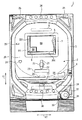
まず、パチンコ遊技機1の概略構成について説明する。図1は、パチンコ遊技機1の概略正面図である。図1に示されるように、パチンコ遊技機1は、遊技球が打ち出される遊技盤2と、遊技盤2を囲む枠部材3とを備えている。枠部材3は、遊技盤2の表面側(図1の紙面手前側)に遊技盤2と所定の間隔を隔てて平行に配置された透明なガラス板(不図示)を支持する部材であり、遊技盤2に対して蝶番(不図示)を介して開閉可能に構成されると共に、遊技盤2に対して着脱可能に構成されている。
[Schematic configuration of pachinko gaming machine 1]
First, a schematic configuration of the pachinko gaming machine 1 will be described. FIG. 1 is a schematic front view of a pachinko gaming machine 1. As shown in FIG. 1, the pachinko gaming machine 1 includes a game board 2 on which game balls are launched, and a frame member 3 surrounding the game board 2. The frame member 3 is a member that supports a transparent glass plate (not shown) disposed in parallel with the game board 2 at a predetermined interval on the front side of the game board 2 (the front side in FIG. 1). The game board 2 is configured to be openable and closable via a hinge (not shown) and is configured to be detachable from the game board 2.
枠部材3に支持されたガラス板と遊技盤2との間には、遊技球が移動する遊技領域20が形成されている。遊技者がハンドル31を握ってレバー32を時計方向へ回転させると、ハンドル31の回転角度に応じた打球力で不図示の発射装置から遊技球が発射される。図には示されていないが、遊技盤2には、発射装置から発射された遊技球を遊技領域20へ案内するガイド部材が設けられており、遊技球は、このガイド部材によって遊技領域20の上部位置へ案内される。遊技球は、遊技領域20に配置された不図示の遊技クギや風車等に接触することでその移動方向を変化させながら、遊技盤2の表面に沿って落下する。
A game area 20 in which a game ball moves is formed between the glass plate supported by the frame member 3 and the game board 2. When the player holds the handle 31 and rotates the lever 32 in the clockwise direction, a game ball is launched from a launching device (not shown) with a hitting force corresponding to the rotation angle of the handle 31. Although not shown in the drawing, the game board 2 is provided with a guide member that guides the game ball launched from the launching device to the game area 20, and the game ball is stored in the game area 20 by the guide member. Guided to the upper position. The game ball falls along the surface of the game board 2 while changing its moving direction by coming into contact with a game nail (not shown) or a windmill arranged in the game area 20.
遊技領域20には、入賞や抽選に関する役物として、第1始動口21、第2始動口22、大入賞口23、普通入賞口24、及びゲート25が設けられている。また、遊技領域20における大入賞口23の下方には、始動口21,22、又は入賞口23,24に入らなかった遊技球を遊技領域20の外へ排出する排出口26が設けられている。
The game area 20 is provided with a first start port 21, a second start port 22, a large winning port 23, a normal winning port 24, and a gate 25, as winning items related to winning and lottery. In addition, a discharge port 26 for discharging game balls that have not entered the start ports 21 and 22 or the winning ports 23 and 24 to the outside of the gaming region 20 is provided below the big winning port 23 in the gaming region 20. .
第1始動口21及び第2始動口22は、後述する液晶表示器5の下方に設けられている。第1始動口21及び第2始動口22は、第1始動口21を第2始動口22の上側として所定の間隔を隔てて上下に並んで配置されている。パチンコ遊技機1では、第1始動口21又は第2始動口22に遊技球が入賞することで、大当たり抽選が実行される。なお、以下の説明では、第1始動口21への遊技球の入賞を契機として実行される大当たり抽選を第1特別図柄抽選と呼び、第2始動口22への遊技球の入賞を契機として実行される大当たり抽選を第2特別図柄抽選と呼び、第1特別図柄抽選及び第2特別図柄抽選を総称して特別図柄抽選と呼ぶものとする。
The first start port 21 and the second start port 22 are provided below the liquid crystal display 5 described later. The first start port 21 and the second start port 22 are arranged side by side at a predetermined interval with the first start port 21 as the upper side of the second start port 22. In the pachinko gaming machine 1, a big hit lottery is executed by winning a game ball in the first start port 21 or the second start port 22. In the following description, the jackpot lottery executed when the game ball is won at the first start port 21 is called a first special symbol lottery, and is executed when the game ball is won at the second start port 22. The jackpot lottery performed is referred to as a second special symbol lottery, and the first special symbol lottery and the second special symbol lottery are collectively referred to as a special symbol lottery.
第1始動口21と第2始動口22との間には、チューリップの花を模した一対の羽根部材を有する電動チューリップ27が配置されている。電動チューリップ27は、一対の羽根部材が閉じた閉姿勢(図1参照)と、一対の羽根部材が開いた開姿勢(不図示)との間で姿勢変化可能に構成されており、不図示の電動ソレノイドが作動することによって姿勢変化する。
Between the 1st starting port 21 and the 2nd starting port 22, the electric tulip 27 which has a pair of blade member imitating a tulip flower is arrange | positioned. The electric tulip 27 is configured to change its posture between a closed posture (see FIG. 1) in which the pair of blade members are closed and an open posture (not shown) in which the pair of blade members are open. The posture is changed by the operation of the electric solenoid.
電動チューリップ27の一対の羽根部材が閉姿勢の状態では、第1始動口21を構成する部材及び電動チューリップ27によって第2始動口22への遊技球の進入経路が塞がれており、遊技球が第2始動口22へ入ることはない。これに対して、遊技球がゲート25を通過すると、普通図柄抽選(電動チューリップ27の開閉抽選)が実行され、この普通図柄抽選に当選すると、電動チューリップ27の一対の羽根部材が規定時間だけ開姿勢を維持した後に閉姿勢に戻る動作が規定回数行われる。このように、普通図柄抽選に当選することで、第2始動口22への遊技球の進入経路が開放されて、遊技球が第2始動口22に入賞可能となる。すなわち、第2特別図柄抽選の実行が可能な状態となる。なお、電動チューリップ27の動作に関する規定時間及び規定回数は、パチンコ遊技機1の遊技状態に応じて変更されることがある。
In a state where the pair of blade members of the electric tulip 27 is in the closed position, the entry path of the game ball to the second start port 22 is blocked by the member constituting the first start port 21 and the electric tulip 27, and the game ball Does not enter the second starting port 22. On the other hand, when the game ball passes through the gate 25, a normal symbol lottery (opening / closing lottery of the electric tulip 27) is executed, and when the normal symbol lottery is won, the pair of blade members of the electric tulip 27 is opened for a specified time. The operation of returning to the closed posture after maintaining the posture is performed a prescribed number of times. Thus, by winning the normal symbol lottery, the approach path of the game ball to the second start port 22 is released, and the game ball can win the second start port 22. That is, the second special symbol lottery can be executed. The specified time and the specified number of times for the operation of the electric tulip 27 may be changed according to the gaming state of the pachinko gaming machine 1.
普通入賞口24は、ゲート25の下方に配置されている。普通入賞口24に遊技球が入賞した場合、抽選は実行されないが、第1始動口21や第2始動口22に遊技球が入賞した場合よりも多い賞球が払い出される。
The normal winning opening 24 is disposed below the gate 25. When a game ball wins the normal winning opening 24, the lottery is not executed, but more prize balls are paid out than when the game ball wins the first start opening 21 and the second start opening 22.
大入賞口23は、第2始動口22の下方に配置されている。大入賞口23は、特別図柄抽選の結果に応じて開放される。大入賞口23の開口部には、大入賞口23を開閉するプレートが設けられている。特別図柄抽選に当選していない状態では、このプレートが遊技盤2の表面と同一平面を形成する姿勢となっているために、大入賞口23に遊技球が入らない状態となっている。これに対して、特別図柄抽選に当選すると、プレートの下端側を軸としてプレートの上端側が遊技盤2の表面側へ傾倒して、大入賞口23が開放される。
The big prize opening 23 is arranged below the second start opening 22. The special winning opening 23 is opened according to the result of the special symbol lottery. A plate for opening and closing the big prize opening 23 is provided at the opening of the big prize opening 23. In a state where the special symbol lottery is not won, since the plate is in the same plane as the surface of the game board 2, the game ball does not enter the big winning opening 23. On the other hand, when the special symbol lottery is won, the upper end side of the plate is tilted toward the surface side of the game board 2 with the lower end side of the plate as an axis, and the special winning opening 23 is opened.
ここで、賞球の払い出しについて説明する。第1始動口21、第2始動口22、大入賞口23、及び普通入賞口24に遊技球が入って入賞すると、入賞した場所に応じた個数の賞球(遊技球)が払い出される。例えば、第1始動口21又は第2始動口22に遊技球が入賞すると4個の賞球が払い出され、大入賞口23に遊技球が入賞すると13個の賞球が払い出され、普通入賞口24に遊技球が入賞すると10個の賞球が払い出される。なお、遊技球がゲート25を通過しても賞球が払い出されることはない。
Here, the payout of prize balls will be described. When a game ball enters the first start port 21, the second start port 22, the big winning port 23, and the normal winning port 24 and wins, a number of award balls (game balls) corresponding to the winning place are paid out. For example, when a game ball is won at the first start port 21 or the second start port 22, four prize balls are paid out, and when a game ball is won at the big prize port 23, 13 prize balls are paid out. When a game ball wins the winning opening 24, 10 winning balls are paid out. Even if the game ball passes through the gate 25, the prize ball is not paid out.
遊技盤2の中央部には、演出のための各種の画像を表示する液晶表示器5及びEL表示器6が設けられている。液晶表示器5及びEL表示器6については、本発明の主要な構成であるため後に詳述する。
A liquid crystal display 5 and an EL display 6 for displaying various images for production are provided at the center of the game board 2. Since the liquid crystal display 5 and the EL display 6 are the main components of the present invention, they will be described in detail later.
液晶表示器5と近接する位置に、各種の演出に用いられる盤ランプ8及び可動役物7が設けられている。盤ランプ8は、遊技者による遊技の進行に応じて発光することによって光による各種の演出を行う。可動役物7は、遊技盤2に対して可動に構成されており、例えば内蔵された発光素子を発光させながら回動することによって各種の演出を行う。なお、本実施形態では、遊技盤2に対して可動に構成された装飾役物が可動役物7のみである場合について説明するが、更に他の可動役物が設けられていてもよい。
A panel lamp 8 and a movable accessory 7 used for various effects are provided at positions close to the liquid crystal display 5. The board lamp 8 emits light according to the progress of the game by the player, thereby performing various effects by light. The movable accessory 7 is configured to be movable with respect to the game board 2, and performs various effects by rotating, for example, a built-in light emitting element. In the present embodiment, the case where the decorative accessory configured to be movable with respect to the game board 2 is only the movable accessory 7 will be described, but another movable accessory may be provided.
図2は、パチンコ遊技機1の一部を示す概略平面図である。図1及び図2に示されるように、枠部材3には、上記ハンドル31及びレバー32の他に、停止ボタン33、取り出しボタン34、スピーカ35、枠ランプ36、演出ボタン37、演出キー38、及び皿39が設けられている。
FIG. 2 is a schematic plan view showing a part of the pachinko gaming machine 1. As shown in FIGS. 1 and 2, the frame member 3 includes a stop button 33, a take-out button 34, a speaker 35, a frame lamp 36, an effect button 37, an effect key 38, in addition to the handle 31 and the lever 32. And a dish 39 are provided.
皿39は、枠部材3からパチンコ遊技機1の正面側へ突出するように設けられており、上述の発射装置へ供給される遊技球を一時的に溜めるものである。この皿39には、上述のように払い出された賞球が排出される。遊技者がハンドル31を握ってレバー32を時計方向へ回転させると、皿39に溜められた遊技球が発射装置へ供給されて、遊技領域20へ所定の時間間隔で発射される。この遊技球の発射は、遊技者が停止ボタン33を押下することによって一時的に停止される。
The tray 39 is provided so as to protrude from the frame member 3 to the front side of the pachinko gaming machine 1, and temporarily stores game balls supplied to the above-described launching device. The prize balls dispensed as described above are discharged to the plate 39. When the player grasps the handle 31 and rotates the lever 32 in the clockwise direction, the game balls stored in the tray 39 are supplied to the launching device and are launched into the game area 20 at predetermined time intervals. The launch of the game ball is temporarily stopped when the player presses the stop button 33.
取り出しボタン34は、皿39と近接する位置に設けられている。遊技者が取り出しボタン34を操作すると、皿39の下面の一部が開口されて、皿39に溜まった遊技球が皿39の下方に配置された不図示の箱へ落下する。なお、この皿39は、1つの皿によって構成されてもよいし、発射装置へ供給される遊技球及び賞球を溜める上皿と、賞球のみを溜める下皿との2つの皿によって構成されてもよい。
The take-out button 34 is provided at a position close to the plate 39. When the player operates the take-out button 34, a part of the lower surface of the tray 39 is opened, and the game balls accumulated on the tray 39 fall into a box (not shown) arranged below the tray 39. The dish 39 may be constituted by one dish, or by two dishes, an upper dish for collecting game balls and prize balls supplied to the launching device, and a lower dish for collecting only prize balls. May be.
スピーカ35は、楽曲や音声、効果音等を出力して音による演出を行う。枠ランプ36は、点灯又は点滅のパターンの変更、発光色の変更、光の照射方向の変更等の光による各種の演出を行う。
The speaker 35 outputs music, sound, sound effects, etc., and performs effects by sound. The frame lamp 36 performs various effects by light, such as changing a lighting or blinking pattern, changing a light emission color, and changing a light irradiation direction.
演出ボタン37及び演出キー38は、それぞれ遊技者が演出に対する操作入力を行うために設けられている。演出ボタン37は、皿39の横に設けられており、演出キー38は、中央キーと中央キーの周辺に配列された複数(ここでは4つ)の周辺キーとを有しており、演出ボタン37に隣接配置されている。後述するが、遊技者が周辺キーのいずれかを押下することによって、EL表示器6を遊技盤2に対して移動させることができる。すなわち、遊技者が演出キー38の周辺キーを操作することによって、EL表示器6の移動方向(上下左右)を指示することができる。また、遊技者が演出キー38の周辺キーを操作することによって、液晶表示器5に表示された複数の選択肢の中からいずれかを選択指示することができる。このように、演出キー38は、遊技者が操作情報を入力するための入力手段として機能する。
The effect button 37 and the effect key 38 are provided for the player to input an operation for the effect, respectively. The effect button 37 is provided on the side of the plate 39, and the effect key 38 has a center key and a plurality of (here, four) peripheral keys arranged around the center key. 37 is disposed adjacently. As will be described later, the EL display 6 can be moved relative to the game board 2 by the player pressing one of the peripheral keys. That is, the player can instruct the moving direction (up / down / left / right) of the EL display 6 by operating the peripheral keys of the effect key 38. In addition, the player can select and instruct one of a plurality of options displayed on the liquid crystal display 5 by operating the peripheral keys of the effect key 38. Thus, the production key 38 functions as an input means for the player to input operation information.
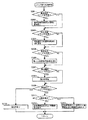
図3は、図1における表示器4の拡大図である。表示器4は、上述した特別図柄抽選や普通図柄抽選の結果や保留数に関する情報を表示するものである。図3に示されるように、表示器4は、第1特別図柄表示器41、第2特別図柄表示器42、第1特別図柄保留表示器43、第2特別図柄保留表示器44、普通図柄表示器45、普通図柄保留表示器46、及び遊技状態表示器47を備えている。
FIG. 3 is an enlarged view of the display 4 in FIG. The display device 4 displays information on the result of the special symbol lottery or the normal symbol lottery described above and the number of holds. As shown in FIG. 3, the display 4 includes a first special symbol display 41, a second special symbol display 42, a first special symbol hold indicator 43, a second special symbol hold indicator 44, and a normal symbol display. A device 45, a normal symbol holding display 46, and a game state display 47 are provided.
第1特別図柄表示器41は、第1始動口21への遊技球の入賞を契機として特別図柄を変動表示してから第1特別図柄抽選の結果を示す特別図柄を停止表示する。第1特別図柄保留表示器43は、第1特別図柄抽選の保留数を表示する。第2特別図柄表示器42は、第2始動口22への遊技球の入賞を契機として特別図柄を変動表示してから第2特別図柄抽選の結果を示す特別図柄を停止表示する。第2特別図柄保留表示器44は、第2特別図柄抽選の保留数を表示する。普通図柄表示器45は、遊技球がゲート25を通過したことを契機として普通図柄を変動表示してから普通図柄抽選の結果を示す普通図柄を停止表示する。普通図柄保留表示器46は、普通図柄抽選の保留数を表示する。遊技状態表示器47は、パチンコ遊技機1の電源投入時点における遊技状態(例えば、通常遊技状態、確変遊技状態、時短遊技状態、潜伏遊技状態)を表示する。
The first special symbol display 41 variably displays the special symbol in response to the winning of the game ball at the first starting port 21, and then stops and displays the special symbol indicating the result of the first special symbol lottery. The first special symbol hold indicator 43 displays the number of holds in the first special symbol lottery. The second special symbol display 42 variably displays the special symbol in response to the winning of the game ball at the second starting port 22, and then stops and displays the special symbol indicating the result of the second special symbol lottery. The second special symbol hold indicator 44 displays the number of holds in the second special symbol lottery. The normal symbol display 45 variably displays the normal symbol in response to the game ball passing through the gate 25, and then stops and displays the normal symbol indicating the result of the normal symbol lottery. The normal symbol hold indicator 46 displays the number of normal symbol lottery holds. The gaming state display 47 displays a gaming state (for example, a normal gaming state, a probability variation gaming state, a short-time gaming state, a latent gaming state) at the time when the power of the pachinko gaming machine 1 is turned on.
ここまでパチンコ遊技機1の概略構成について説明したが、上述したパチンコ遊技機1の構成は単なる一例であって、遊技盤2の盤面構成(入賞や抽選に関する役物の配置)等は、適宜変更されてもよい。例えば本発明に係る遊技機が右打ちが必要なパチンコ遊技機に適用される場合には、大入賞口23やゲート25等を液晶表示器5に対して右側の遊技領域20に配置するといった変更が行われる。
Although the schematic configuration of the pachinko gaming machine 1 has been described so far, the configuration of the pachinko gaming machine 1 described above is merely an example, and the board configuration of the gaming board 2 (arrangement of prizes related to winnings and lotteries) and the like are changed as appropriate. May be. For example, when the gaming machine according to the present invention is applied to a pachinko gaming machine that needs to be right-handed, a change is made such that the big prize opening 23, the gate 25, and the like are arranged in the gaming area 20 on the right side of the liquid crystal display 5. Is done.
ところで、液晶表示器5が遊技者が視認し易い位置に固定されているので、特別図柄抽選に当選しない期間が長時間続いたとき等に遊技者の視点が固定され易く、遊技が単調になるおそれがある。そこで、本実施形態に係るパチンコ遊技機1は、自動的に或いは遊技者による演出キー38の操作に基づいてEL表示器6を移動させ、液晶表示器5の液晶画面50(図1参照)に表示された表示オブジェクト(例えばキャラクタ)をEL表示器6のEL画面60を通して視認可能な位置へEL表示器6が移動したときに、表示オブジェクトに関連する表示内容を示す画像をEL画面60に表示することで、遊技者の視点が固定されにくい効果的な演出が行われるように構成されている。
By the way, since the liquid crystal display 5 is fixed at a position that is easy for the player to visually recognize, the player's viewpoint is easily fixed when the period not winning the special symbol lottery lasts for a long time, and the game becomes monotonous. There is a fear. Therefore, the pachinko gaming machine 1 according to the present embodiment moves the EL display 6 automatically or based on the operation of the effect key 38 by the player, and displays the liquid crystal screen 50 (see FIG. 1) of the liquid crystal display 5. When the displayed display object (for example, a character) is moved to a position where it can be viewed through the EL screen 60 of the EL display 6, an image showing the display contents related to the display object is displayed on the EL screen 60. By doing so, it is configured such that an effective performance in which the player's viewpoint is hard to be fixed is performed.
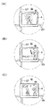
例えば図4(A)に例示されるように、液晶画面50に表示されたキャラクタをEL画面60を通して視認可能な位置にEL表示器6が移動したときに、そのキャラクタの演出効果を高める装飾画像がEL画面60に表示される。その結果、キャラクタは、液晶画面50だけでは表現できない特別な態様で表示されることになる。
For example, as illustrated in FIG. 4A, when the EL display 6 moves to a position where the character displayed on the liquid crystal screen 50 can be seen through the EL screen 60, a decorative image that enhances the effect of the character. Is displayed on the EL screen 60. As a result, the character is displayed in a special manner that cannot be expressed by the liquid crystal screen 50 alone.
また、例えば図4(B)及び図4(C)に例示されるように、液晶画面50に表示されたキャラクタをEL画面60を通して視認可能な位置にEL表示器6が移動したときに、液晶画面50上で行われる表示演出が進行した結果としてのキャラクタの状態を予告する表示内容の予告画像がEL画面60に表示される。図4(B)示される例では、特別図柄の変動表示中(リーチ演出中)に液晶画面50上で行われる表示演出としてキャラクタが敵キャラクタと対戦して勝利したら大当たりとなるようなバトル演出が行われた結果、キャラクタが勝利することを予告する「チャンス!?」という文字情報と共に、液晶画面50上のキャラクタが剣を持った画像を遊技者が視認できるように剣の画像が予告画像としてEL画面60に表示されている。一方の図4(C)に示される例では、上記バトル演出が行われた結果、キャラクタが敗北することを予告する「ピンチ!?」という文字情報と共に、液晶画面50上のキャラクタがバトルに敗れて膝をついた状態を示すキャラクタの画像が予告画像としてEL画面60に表示されている。以下、このような効果的な表示演出を実現するためのパチンコ遊技機1の構成及び動作について説明する。
For example, as illustrated in FIGS. 4B and 4C, when the EL display 6 moves to a position where the character displayed on the liquid crystal screen 50 is visible through the EL screen 60, the liquid crystal is displayed. A notice image of display contents for giving a notice of the state of the character as a result of the progress of the display effect performed on the screen 50 is displayed on the EL screen 60. In the example shown in FIG. 4B, a battle effect that is a big hit if a character wins against an enemy character as a display effect performed on the liquid crystal screen 50 during a special symbol variation display (during a reach effect). As a result, the image of the sword is used as a preview image so that the player can visually recognize the image of the character on the LCD screen 50 holding the sword, together with the character information “Chance !?” that predicts that the character will win. It is displayed on the EL screen 60. On the other hand, in the example shown in FIG. 4C, the character on the liquid crystal screen 50 is defeated in the battle together with the character information “Pinch !?” that warns that the character is defeated as a result of the battle effect. An image of the character indicating the state of being kneeled is displayed on the EL screen 60 as a preview image. Hereinafter, the configuration and operation of the pachinko gaming machine 1 for realizing such an effective display effect will be described.
[液晶表示器5の構成]
液晶表示器5(本発明の第1画像表示器の一例)は、遊技盤2を支持するパチンコ遊技機1の筐体に固定されている。このため、液晶表示器5は、遊技盤2に対して固定されている。液晶表示器5としては、例えば垂直方向11の画素数が「600」で、水平方向12の画素数が「800」という画面解像度(垂直画素数×水平画素数)の液晶画面50(本発明の第1表示画面の一例)を有する液晶ディスプレイが使用される。液晶表示器5は、後述する画像音響制御部140(図11参照)から出力される画像を液晶画面50に表示する。液晶画面50には、例えば、特別図柄抽選の結果を報知するための装飾図柄、予告演出を行うキャラクタやアイテム、特別図柄抽選が保留されていることを示す保留表示画像等の表示オブジェクトが表示される。
[Configuration of Liquid Crystal Display 5]
The liquid crystal display 5 (an example of the first image display according to the present invention) is fixed to the housing of the pachinko gaming machine 1 that supports the game board 2. For this reason, the liquid crystal display 5 is fixed to the game board 2. As the liquid crystal display 5, for example, a liquid crystal screen 50 having a screen resolution (vertical pixel number × horizontal pixel number) of “600” in the vertical direction 11 and “800” in the horizontal direction 12 (the number of pixels in the present invention). A liquid crystal display having an example of a first display screen is used. The liquid crystal display 5 displays an image output from an image sound control unit 140 (see FIG. 11) described later on the liquid crystal screen 50. On the liquid crystal screen 50, for example, display objects such as decorative symbols for informing the result of the special symbol lottery, characters and items for performing a notice effect, a hold display image indicating that the special symbol lottery is put on hold are displayed. The
図5は、液晶画面50の概略構成を示す図である。図5に示されるように、液晶画面50は、多数の画素ユニット51を有して構成されている。画素ユニット51は、垂直方向11に600個、水平方向12に800個並んで配置されているが、説明の便宜上、図5(A)では、実際よりも少なく画素ユニット51が表記されている。
FIG. 5 is a diagram showing a schematic configuration of the liquid crystal screen 50. As shown in FIG. 5, the liquid crystal screen 50 has a large number of pixel units 51. Although 600 pixel units 51 are arranged in the vertical direction 11 and 800 pixel units are arranged in the horizontal direction 12, for convenience of explanation, in FIG. 5A, fewer pixel units 51 are shown than in actuality.
画素ユニット51は、カラー液晶素子52及び光センサ56を有している。カラー液晶素子52は、3原色のそれぞれの色を表示するR(Red)色液晶素子53、G(Green)色液晶素子54、及びB(Blue)色液晶素子55から構成されている。光センサ56は、液晶画面50の前方からの光を検知する受光素子であり、R色液晶素子53、G色液晶素子54、及びB色液晶素子55と隣接するように配置されている(図5(B)参照)。このように、光センサ56は、各カラー液晶素子52のそれぞれに近接配置されている。
The pixel unit 51 includes a color liquid crystal element 52 and an optical sensor 56. The color liquid crystal element 52 includes an R (Red) color liquid crystal element 53, a G (Green) color liquid crystal element 54, and a B (Blue) color liquid crystal element 55 that display the three primary colors. The optical sensor 56 is a light receiving element that detects light from the front of the liquid crystal screen 50, and is disposed adjacent to the R color liquid crystal element 53, the G color liquid crystal element 54, and the B color liquid crystal element 55 (see FIG. 5 (B)). Thus, the optical sensor 56 is disposed in proximity to each color liquid crystal element 52.
光センサ56が光を受光すると、受光した光の輝度に応じた電気信号が生成される。液晶画面50が有する各光センサ56は、後述する演出制御部130(図11参照)に接続されており、各光センサ56で生成された電気信号は演出制御部130に出力される。演出制御部130は、各光センサ56から出力される電気信号に基づいて、EL表示器6のEL画面60の位置を検出する。具体的には、後述するEL表示器6のフレーム61(図7参照)は、液晶表示器5の液晶画面50と対向する面が黒色に形成されており、液晶画面50においてフレーム61によって覆われた領域に設けられている光センサ56からは、フレーム61によって覆われていない領域に設けられている光センサ56から出力される電気信号とは異なるレベルの電気信号が出力される。図6には、液晶表示器5の液晶画面50に対してEL表示器6のEL画面60が左下方に位置したときにフレーム61によって覆われた領域16(ハッチングされた領域)が示されている。演出制御部130は、各光センサ56から出力される電気信号のレベルの違いに基づいて、フレーム61の位置、すなわちEL画面60の位置を検出することができる。
When the optical sensor 56 receives light, an electrical signal corresponding to the brightness of the received light is generated. Each optical sensor 56 included in the liquid crystal screen 50 is connected to an effect control unit 130 (see FIG. 11) described later, and an electrical signal generated by each optical sensor 56 is output to the effect control unit 130. The effect control unit 130 detects the position of the EL screen 60 of the EL display 6 based on the electrical signal output from each optical sensor 56. Specifically, a frame 61 (see FIG. 7) of the EL display 6 to be described later has a surface facing the liquid crystal screen 50 of the liquid crystal display 5 formed in black, and is covered with the frame 61 on the liquid crystal screen 50. From the optical sensor 56 provided in the region, an electrical signal of a level different from the electrical signal output from the optical sensor 56 provided in the region not covered by the frame 61 is output. FIG. 6 shows a region 16 (hatched region) covered by the frame 61 when the EL screen 60 of the EL display 6 is positioned on the lower left side with respect to the liquid crystal screen 50 of the liquid crystal display 5. Yes. The effect control unit 130 can detect the position of the frame 61, that is, the position of the EL screen 60 based on the difference in level of the electrical signal output from each optical sensor 56.
図5(B)に示されるように、画素ユニット51には、画素ユニット51と隣接する他の画素ユニットとを区画する外壁57、及び画素ユニット51を構成するカラー液晶素子52と光センサ56とを区画する内壁58が設けられている。外壁57は、カラー液晶素子52及び光センサ56の外側を囲み、且つ画素ユニット51の基部から液晶画面50の前方へ向けて突出するように形成されている。内壁58は、カラー液晶素子52と光センサ56との間に画素ユニット51の基部から液晶画面50の前方へ向けて突出するように形成されている。この外壁57及び内壁58が設けられていることにより、光センサ56に対して近接するカラー液晶素子52から光が直接入射することが防止されるので、液晶画面50の前方からの光を各光センサ56で正確に検知して、EL表示器6の位置を精度良く検出することができる。
As shown in FIG. 5B, the pixel unit 51 includes an outer wall 57 that partitions the pixel unit 51 and other adjacent pixel units, a color liquid crystal element 52 that constitutes the pixel unit 51, and an optical sensor 56. Is provided. The outer wall 57 surrounds the color liquid crystal element 52 and the optical sensor 56 and is formed so as to protrude from the base of the pixel unit 51 toward the front of the liquid crystal screen 50. The inner wall 58 is formed between the color liquid crystal element 52 and the optical sensor 56 so as to protrude from the base of the pixel unit 51 toward the front of the liquid crystal screen 50. Since the outer wall 57 and the inner wall 58 are provided, it is possible to prevent light from directly entering from the color liquid crystal element 52 adjacent to the optical sensor 56, so that light from the front of the liquid crystal screen 50 is transmitted to each light. It is possible to accurately detect the position of the EL display 6 by accurately detecting with the sensor 56.
[EL表示器6の構成]
EL表示器6(本発明の第2画像表示器の一例)は、液晶表示器5の前面側に液晶画面50と所定の間隔を隔てて配置されており、後述する駆動機構10を介して伝達される第1ステッピングモータ29及び第2ステッピングモータ30の駆動力を受けて液晶画面50の表面に沿って上下左右に移動可能である。本実施形態におけるEL表示器6は、透明なEL画面60(本発明の第2表示画面の一例)に画像を単色表示する透明ELディスプレイである。EL画面60は、樹脂製のフレーム61に形成された開口部に嵌め込まれることによってフレーム61に固定されている。EL画面60としては、例えば垂直方向11の画素数が「240」で、水平方向12の画素数が「320」という画面解像度を有するものが使用される。したがって、液晶表示器5及びEL表示器6は、EL画面60よりも液晶画面50の方が画面解像度が大きくなるように構成されている。
[Configuration of EL Display 6]
The EL display 6 (an example of the second image display of the present invention) is disposed on the front side of the liquid crystal display 5 with a predetermined distance from the liquid crystal screen 50, and is transmitted via a drive mechanism 10 described later. The first stepping motor 29 and the second stepping motor 30 that are driven can be moved up and down and left and right along the surface of the liquid crystal screen 50. The EL display 6 in this embodiment is a transparent EL display that displays an image in a single color on a transparent EL screen 60 (an example of the second display screen of the present invention). The EL screen 60 is fixed to the frame 61 by being fitted into an opening formed in a resin frame 61. As the EL screen 60, for example, a screen having a screen resolution of “240” in the vertical direction 11 and “320” in the horizontal direction 12 is used. Accordingly, the liquid crystal display 5 and the EL display 6 are configured such that the screen resolution of the liquid crystal screen 50 is larger than that of the EL screen 60.
EL表示器6として透過型のELディスプレイが使用されるので、EL画面60に画像が表示された状態であっても、遊技者がEL表示器6の裏面側に位置するオブジェクト(液晶画面50に表示されたキャラクタやアイテムといった表示オブジェクト、可動役物7等)をEL画面60を通して視認することができる。なお、EL表示器6のフレーム61の裏面(液晶画面50と対向する面)は、上述のように、黒色に形成されている。
Since a transmissive EL display is used as the EL display 6, even if an image is displayed on the EL screen 60, an object (on the liquid crystal screen 50) the player is positioned on the back side of the EL display 6. Displayed objects such as displayed characters and items, movable accessories 7, etc.) can be viewed through the EL screen 60. Note that the back surface (the surface facing the liquid crystal screen 50) of the frame 61 of the EL display 6 is formed in black as described above.
[駆動機構10の構成及び動作]
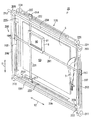
次に、図7〜図10を参照しつつ、EL表示器6を移動させる駆動機構10について説明する。図7は、駆動機構10の構成を示す斜視図であり、液晶画面50に表示された表示オブジェクトをEL画面60を通して視認可能な位置にEL表示器6が位置した状態を示している。図8は、駆動機構10の構成を示す斜視図であり、可動役物7の一部をEL画面60を通して視認可能な位置にEL表示器6が位置した状態を示している。図9は、駆動機構10の分解斜視図である。図10は、EL表示器6の拡大斜視図である。
[Configuration and Operation of Drive Mechanism 10]
Next, the drive mechanism 10 that moves the EL display 6 will be described with reference to FIGS. FIG. 7 is a perspective view showing the configuration of the driving mechanism 10 and shows a state in which the EL display 6 is located at a position where the display object displayed on the liquid crystal screen 50 can be visually recognized through the EL screen 60. FIG. 8 is a perspective view showing the configuration of the drive mechanism 10 and shows a state in which the EL display 6 is located at a position where a part of the movable accessory 7 can be seen through the EL screen 60. FIG. 9 is an exploded perspective view of the drive mechanism 10. FIG. 10 is an enlarged perspective view of the EL display 6.
駆動機構10は、EL表示器6を液晶表示器5の液晶画面50に沿って上下左右に移動させるものである。本実施形態においては、駆動機構10は、第1ステッピングモータ29(図11参照)の駆動力をEL表示器6に伝達して、EL表示器6を液晶画面50に沿って垂直方向11(図1参照)に移動させる昇降駆動機構200と、第2ステッピングモータ30(図11参照)の駆動力をEL表示器6に伝達して、EL表示器6を液晶画面50に沿って水平方向12(図1参照)に移動させるスライド駆動機構220とから構成されている。
The drive mechanism 10 moves the EL display 6 vertically and horizontally along the liquid crystal screen 50 of the liquid crystal display 5. In the present embodiment, the drive mechanism 10 transmits the driving force of the first stepping motor 29 (see FIG. 11) to the EL display 6, and causes the EL display 6 to move along the liquid crystal screen 50 in the vertical direction 11 (FIG. 1) and the driving force of the second stepping motor 30 (see FIG. 11) is transmitted to the EL display 6, and the EL display 6 is moved along the liquid crystal screen 50 in the horizontal direction 12 (see FIG. And a slide drive mechanism 220 that is moved to (see FIG. 1).
昇降駆動機構200は、大別して、第1支持部材201、ガイド部材202、ガイド部材203、第1回転軸204、第2回転軸205、第1駆動ベルト206、及び第2駆動ベルト207を備えている。
The elevating drive mechanism 200 includes a first support member 201, a guide member 202, a guide member 203, a first rotating shaft 204, a second rotating shaft 205, a first driving belt 206, and a second driving belt 207. Yes.
第1支持部材201は、水平方向12を長手方向とする薄い板状部材である。この第1支持部材201は、図1に示されるように、液晶表示器5の液晶画面50の手前に配置されるため、液晶画面50に表示された画像の視認性の低下を最低限に抑えるために、透明な樹脂で形成されている。EL表示器6のフレーム61には、水平方向12に貫通する挿通孔62(図9及び図10参照)が形成されており、第1支持部材201は、挿通孔62に挿通されることによってフレーム61を水平方向12へ移動可能に支持する。
The first support member 201 is a thin plate-like member having the horizontal direction 12 as a longitudinal direction. As shown in FIG. 1, the first support member 201 is disposed in front of the liquid crystal screen 50 of the liquid crystal display 5, so that a reduction in the visibility of an image displayed on the liquid crystal screen 50 is minimized. Therefore, it is formed of a transparent resin. An insertion hole 62 (see FIGS. 9 and 10) penetrating in the horizontal direction 12 is formed in the frame 61 of the EL display 6, and the first support member 201 is inserted into the insertion hole 62 to form the frame. 61 is supported so as to be movable in the horizontal direction 12.
図10に示されるように、第1支持部材201は、その一端側に連結部材194が固定されると共に、その他端側に連結部材197が固定されている。連結部材194は、ガイド部材202(図9参照)が挿通される円筒状の挿通孔195と、第1駆動ベルト206(図9参照)を挟持する挟持片196とを有している。ガイド部材202は、断面外形が円形の棒状部材であり、その長手方向が垂直方向11と一致するようにパチンコ遊技機1の筐体に固定されている。ガイド部材202の外径寸法は、挿通孔195の内径寸法よりも若干小さく設定されており、連結部材194は、挿通孔195にガイド部材202が挿通されることによって、垂直方向11へ移動可能にガイド部材202によって支持される。
As shown in FIG. 10, the first support member 201 has a connecting member 194 fixed to one end side and a connecting member 197 fixed to the other end side. The connecting member 194 includes a cylindrical insertion hole 195 through which the guide member 202 (see FIG. 9) is inserted, and a holding piece 196 that holds the first drive belt 206 (see FIG. 9). The guide member 202 is a rod-shaped member having a circular cross-sectional outer shape, and is fixed to the housing of the pachinko gaming machine 1 so that the longitudinal direction thereof coincides with the vertical direction 11. The outer diameter dimension of the guide member 202 is set slightly smaller than the inner diameter dimension of the insertion hole 195, and the connecting member 194 is movable in the vertical direction 11 when the guide member 202 is inserted into the insertion hole 195. Supported by the guide member 202.
連結部材197は、連結部材194と同形状の部材であって、ガイド部材203(図9参照)が挿通される挿通孔198と、第2駆動ベルト207(図9参照)を挟持する挟持片199とを有している。ガイド部材203は、ガイド部材202と同形状の部材であって、ガイド部材202と所定の間隔を隔てて対向するようにパチンコ遊技機1の筐体に固定されている。連結部材197は、挿通孔198にガイド部材203が挿通されることによって、垂直方向11へ移動可能にガイド部材203によって支持される。
The connecting member 197 is a member having the same shape as that of the connecting member 194, and a holding piece 199 that holds the insertion hole 198 through which the guide member 203 (see FIG. 9) is inserted and the second drive belt 207 (see FIG. 9). And have. The guide member 203 is a member having the same shape as the guide member 202 and is fixed to the housing of the pachinko gaming machine 1 so as to face the guide member 202 with a predetermined interval. The connecting member 197 is supported by the guide member 203 so as to be movable in the vertical direction 11 by inserting the guide member 203 through the insertion hole 198.
このように連結部材194及び連結部材197がガイド部材202及びガイド部材203に支持されているので、第1支持部材201は、垂直方向11へスライド可能である。
Thus, since the connecting member 194 and the connecting member 197 are supported by the guide member 202 and the guide member 203, the first support member 201 can slide in the vertical direction 11.
ガイド部材202,203の上側に第1回転軸204が設けられると共に、ガイド部材202,203の下側に第2回転軸205が設けられている(図7及び図8参照)。第1回転軸204及び第2回転軸205は、それぞれ軸方向が水平方向12と一致するように、不図示の軸受けに回転可能に支持されている。図9に示されるように、第1回転軸204は、その一端側にギヤ212及びプーリ208が固定されると共に、その他端にプーリ209が固定されている。第2回転軸205は、その一端にプーリ210が固定されると共に、その他端にプーリ211が固定されている。
A first rotation shaft 204 is provided above the guide members 202 and 203, and a second rotation shaft 205 is provided below the guide members 202 and 203 (see FIGS. 7 and 8). The first rotating shaft 204 and the second rotating shaft 205 are rotatably supported by a bearing (not shown) so that the axial direction thereof coincides with the horizontal direction 12. As shown in FIG. 9, the first rotary shaft 204 has a gear 212 and a pulley 208 fixed to one end thereof, and a pulley 209 fixed to the other end. The second rotating shaft 205 has a pulley 210 fixed to one end thereof and a pulley 211 fixed to the other end thereof.
プーリ208とプーリ210との間には、内側に歯が形成された無端環状の第1駆動ベルト206が張り渡されている。プーリ209とプーリ211との間には、第1駆動ベルト206と同じ構成の第2駆動ベルト207が張り渡されている。
Between the pulley 208 and the pulley 210, an endless first drive belt 206 having teeth formed on the inside is stretched. A second drive belt 207 having the same configuration as the first drive belt 206 is stretched between the pulley 209 and the pulley 211.
第1回転軸204のギヤ212(図7参照)には、第1ステッピングモータ29(図11参照)の駆動力が入力される。これにより、ギヤ212が固定された第1回転軸204が回転する。プーリ208〜211の外周には、第1駆動ベルト206及び第2駆動ベルト207の歯と噛合する歯が形成されており、第1回転軸204の回転力がプーリ208,209を介して第1駆動ベルト206及び第2駆動ベルト207に伝達される。その結果、第1駆動ベルト206及び第2駆動ベルト207が周運動すると共に、第1回転軸204及び第2回転軸205が同期回転する。この第1駆動ベルト206及び第2駆動ベルト207には、第1支持部材201の両端に固定された連結部材194,197が挟持片196,199によって固定されているので、第1ステッピングモータ29の駆動力が第1支持部材201にも伝達されて、第1支持部材201に支持されたEL表示器6が垂直方向11へ移動する。なお、第1ステッピングモータ29の回転方向を正回転又は逆回転に切り換えることで、垂直方向11におけるEL表示器6の移動方向を切り換えることができる。
The driving force of the first stepping motor 29 (see FIG. 11) is input to the gear 212 (see FIG. 7) of the first rotating shaft 204. Thereby, the 1st rotating shaft 204 to which the gear 212 was fixed rotates. Teeth that mesh with the teeth of the first drive belt 206 and the second drive belt 207 are formed on the outer circumferences of the pulleys 208 to 211, and the rotational force of the first rotating shaft 204 is first via the pulleys 208 and 209. It is transmitted to the drive belt 206 and the second drive belt 207. As a result, the first drive belt 206 and the second drive belt 207 move circumferentially, and the first rotation shaft 204 and the second rotation shaft 205 rotate synchronously. Since the connecting members 194 and 197 fixed to both ends of the first support member 201 are fixed to the first drive belt 206 and the second drive belt 207 by sandwiching pieces 196 and 199, the first stepping motor 29 The driving force is also transmitted to the first support member 201 and the EL display 6 supported by the first support member 201 moves in the vertical direction 11. Note that the direction of movement of the EL display 6 in the vertical direction 11 can be switched by switching the rotation direction of the first stepping motor 29 to forward rotation or reverse rotation.
一方、スライド駆動機構220は、大別して、第2支持部材221、ガイド部材222、ガイド部材223、第1回転軸224、第2回転軸225、第1駆動ベルト226、及び第2駆動ベルト227を備えている。
On the other hand, the slide drive mechanism 220 is roughly divided into a second support member 221, a guide member 222, a guide member 223, a first rotation shaft 224, a second rotation shaft 225, a first drive belt 226, and a second drive belt 227. I have.
第2支持部材221は、垂直方向11を長手方向とする薄い板状部材である。この第2支持部材221は、第1支持部材201と同様に、透明な樹脂で形成されている。EL表示器6のフレーム61には、垂直方向11に貫通する挿通孔63(図9及び図10参照)が形成されており、第2支持部材221は、挿通孔63に挿通されることによってフレーム61を垂直方向11へ移動可能に支持する。
The second support member 221 is a thin plate member whose longitudinal direction is the vertical direction 11. Similar to the first support member 201, the second support member 221 is formed of a transparent resin. An insertion hole 63 (see FIGS. 9 and 10) penetrating in the vertical direction 11 is formed in the frame 61 of the EL display 6, and the second support member 221 is inserted into the insertion hole 63 so that the frame 61 is supported so as to be movable in the vertical direction 11.
図10に示されるように、第2支持部材221は、その一端側に連結部材214が固定されると共に、その他端側に連結部材217が固定されている。連結部材214は、ガイド部材222(図9参照)が挿通される円筒状の挿通孔215と、第2駆動ベルト227(図9参照)を挟持する挟持片216とを有している。ガイド部材222は、断面外形が円形の棒状部材であり、その長手方向が水平方向12と一致するように、パチンコ遊技機1の筐体に固定されている。ガイド部材222の外径寸法は、挿通孔215の内径寸法よりも若干小さく設定されており、連結部材214は、挿通孔215にガイド部材222が挿通されることによって、水平方向12へ移動可能にガイド部材222によって支持される。
As shown in FIG. 10, the second support member 221 has a connecting member 214 fixed to one end thereof and a connecting member 217 fixed to the other end thereof. The connecting member 214 has a cylindrical insertion hole 215 through which the guide member 222 (see FIG. 9) is inserted, and a holding piece 216 that holds the second drive belt 227 (see FIG. 9). The guide member 222 is a rod-shaped member having a circular cross-sectional outer shape, and is fixed to the housing of the pachinko gaming machine 1 so that the longitudinal direction thereof coincides with the horizontal direction 12. The outer diameter dimension of the guide member 222 is set slightly smaller than the inner diameter dimension of the insertion hole 215, and the connecting member 214 is movable in the horizontal direction 12 by inserting the guide member 222 into the insertion hole 215. Supported by the guide member 222.
連結部材217は、連結部材214と同形状の部材であって、ガイド部材223(図9参照)が挿通される挿通孔218と、第1駆動ベルト226(図9参照)を挟持する挟持片219とを有している。ガイド部材223は、ガイド部材222と同形状の部材であって、ガイド部材222と所定の間隔を隔てて対向するようにパチンコ遊技機1の筐体に固定されている。連結部材217は、挿通孔218にガイド部材223が挿通されることによって、水平方向12へ移動可能にガイド部材223によって支持される。
The connecting member 217 is a member having the same shape as the connecting member 214, and includes an insertion hole 218 through which the guide member 223 (see FIG. 9) is inserted, and a holding piece 219 that holds the first drive belt 226 (see FIG. 9). And have. The guide member 223 is a member having the same shape as the guide member 222, and is fixed to the housing of the pachinko gaming machine 1 so as to face the guide member 222 with a predetermined interval. The connecting member 217 is supported by the guide member 223 so as to be movable in the horizontal direction 12 by inserting the guide member 223 through the insertion hole 218.
このように連結部材214及び連結部材217がガイド部材222及びガイド部材223に支持されているので、第2支持部材221は、水平方向12へスライド可能である。
Thus, since the connecting member 214 and the connecting member 217 are supported by the guide member 222 and the guide member 223, the second support member 221 is slidable in the horizontal direction 12.
水平方向12におけるガイド部材222,223の外側に、第1回転軸224及び第2回転軸225が設けられている(図7及び図8参照)。第1回転軸224及び第2回転軸225は、それぞれ軸方向が垂直方向11と一致するように、不図示の軸受けに回転可能に支持されている。図9に示されるように、第1回転軸224は、その一端側にギヤ232及びプーリ228が固定されると共に、その他端にプーリ229が固定されている。第2回転軸225は、その一端にプーリ230が固定されると共に、その他端にプーリ231が固定されている。
A first rotating shaft 224 and a second rotating shaft 225 are provided outside the guide members 222 and 223 in the horizontal direction 12 (see FIGS. 7 and 8). The first rotating shaft 224 and the second rotating shaft 225 are rotatably supported by a bearing (not shown) such that the axial direction thereof coincides with the vertical direction 11. As shown in FIG. 9, the first rotating shaft 224 has a gear 232 and a pulley 228 fixed to one end thereof, and a pulley 229 fixed to the other end. The second rotating shaft 225 has a pulley 230 fixed to one end and a pulley 231 fixed to the other end.
プーリ228とプーリ230との間には、内側に歯が形成された無端環状の第1駆動ベルト226が張り渡されている。プーリ229とプーリ231との間には、第1駆動ベルト226と同じ構成の第2駆動ベルト227が張り渡されている。
Between the pulley 228 and the pulley 230, an endless annular first drive belt 226 having teeth formed inside is stretched. A second drive belt 227 having the same configuration as the first drive belt 226 is stretched between the pulley 229 and the pulley 231.
第1回転軸224のギヤ232(図7参照)には、第2ステッピングモータ30(図11参照)の駆動力が入力される。これにより、ギヤ232が固定された第1回転軸224が回転する。プーリ228〜231の外周には、第1駆動ベルト226及び第2駆動ベルト227の歯と噛合する歯が形成されており、第1回転軸224の回転力がプーリ228,229を介して第1駆動ベルト226及び第2駆動ベルト227に伝達される。その結果、第1駆動ベルト226及び第2駆動ベルト227が周運動すると共に、第1回転軸224及び第2回転軸225が同期回転する。この第1駆動ベルト226及び第2駆動ベルト227には、第2支持部材221の両端に固定された連結部材214,217が挟持片216,219によって固定されているので、第2ステッピングモータ30の駆動力が第2支持部材221にも伝達されて、第2支持部材221に支持されたEL表示器6が水平方向12へ移動する。なお、第2ステッピングモータ30の回転方向を正回転又は逆回転に切り換えることで、水平方向12におけるEL表示器6の移動方向を切り換えることができる。
The driving force of the second stepping motor 30 (see FIG. 11) is input to the gear 232 (see FIG. 7) of the first rotating shaft 224. Thereby, the 1st rotating shaft 224 to which the gear 232 was fixed rotates. Teeth that mesh with the teeth of the first drive belt 226 and the second drive belt 227 are formed on the outer circumferences of the pulleys 228 to 231, and the rotational force of the first rotating shaft 224 is first via the pulleys 228 and 229. It is transmitted to the drive belt 226 and the second drive belt 227. As a result, the first drive belt 226 and the second drive belt 227 move circumferentially, and the first rotation shaft 224 and the second rotation shaft 225 rotate synchronously. Since the first driving belt 226 and the second driving belt 227 have connecting members 214 and 217 fixed to both ends of the second support member 221 fixed by sandwiching pieces 216 and 219, the second stepping motor 30 The driving force is also transmitted to the second support member 221 so that the EL display 6 supported by the second support member 221 moves in the horizontal direction 12. Note that the moving direction of the EL display 6 in the horizontal direction 12 can be switched by switching the rotation direction of the second stepping motor 30 to forward rotation or reverse rotation.
このように、EL表示器6は、昇降駆動機構200によって垂直方向11へ移動し、スライド駆動機構220によって水平方向12へ移動する。なお、本実施形態では、演出キー38から入力される操作情報に応じてEL表示器6が移動するので、遊技者は、所望の位置へEL表示器6を移動させることができる。なお、第1支持部材201及び第2支持部材221を除く駆動機構10の各構成部材は、液晶表示器5等が設けられた領域と遊技領域20とを区画する化粧カバー14(図1参照)によって覆われているために、図1には現れていない。
Thus, the EL display 6 moves in the vertical direction 11 by the lifting drive mechanism 200 and moves in the horizontal direction 12 by the slide drive mechanism 220. In the present embodiment, since the EL display 6 moves in accordance with the operation information input from the effect key 38, the player can move the EL display 6 to a desired position. In addition, each component of the drive mechanism 10 excluding the first support member 201 and the second support member 221 is a decorative cover 14 that partitions the region where the liquid crystal display 5 and the like are provided from the game region 20 (see FIG. 1). 1 does not appear in FIG.
[パチンコ遊技機1の制御装置の構成]
遊技盤2の裏面側(図1の紙面奥側)には、賞球として払い出される遊技球を溜めておく球タンクの他に、パチンコ遊技機1の動作を制御する制御装置が設けられている。図には示されていないが、この制御装置は、メイン基板及びサブ基板を有している。メイン基板は、内部抽選や当選の判定等を行う遊技制御部100として機能するメイン制御基板、賞球の払い出しを制御する払出制御部120として機能する払出制御基板等から構成されている。このメイン基板は、メイン基板が改変された場合にその痕跡が残るように、透明部材で構成されたケース内に密閉状態で配置されている。一方のサブ基板は、演出を統括的に制御する演出制御部130として機能する演出制御基板、画像や音による演出を制御する画像音響制御部140として機能する画像音響制御基板、及び各種のランプ(枠ランプ36や盤ランプ8)や可動役物7による演出を制御するランプ制御部150として機能するランプ制御基板等から構成されている。
[Configuration of control device of pachinko gaming machine 1]
On the back side of the game board 2 (the back side in FIG. 1), a control device for controlling the operation of the pachinko gaming machine 1 is provided in addition to a ball tank for storing game balls to be paid out as prize balls. . Although not shown in the figure, the control device has a main board and a sub board. The main board includes a main control board that functions as a game control unit 100 that performs internal lottery and determination of winning, a payout control board that functions as a payout control unit 120 that controls payout of prize balls. The main board is disposed in a sealed state in a case made of a transparent member so that a trace remains when the main board is modified. One of the sub-boards is an effect control board that functions as an effect control section 130 that comprehensively controls the effects, an image sound control board that functions as an image sound control section 140 that controls effects by images and sounds, and various lamps ( The lamp control board 150 functions as a lamp control unit 150 that controls the effects of the frame lamp 36, the panel lamp 8) and the movable accessory 7.
以下、図11を参照しつつ、パチンコ遊技機1の制御装置の構成について説明する。ここで、図11は、パチンコ遊技機1の制御装置の構成の一例を示すブロック図である。図11に示されるように、パチンコ遊技機1の制御装置は、遊技制御部100、払出制御部120、演出制御部130、画像音響制御部140、及びランプ制御部150を備えている。
Hereinafter, the configuration of the control device of the pachinko gaming machine 1 will be described with reference to FIG. Here, FIG. 11 is a block diagram showing an example of the configuration of the control device of the pachinko gaming machine 1. As shown in FIG. 11, the control device of the pachinko gaming machine 1 includes a game control unit 100, a payout control unit 120, an effect control unit 130, an image sound control unit 140, and a lamp control unit 150.
[遊技制御部100の構成]
遊技制御部100は、CPU101、ROM102、及びRAM103を備えている。CPU101は、ROM102に記憶されたプログラムに基づいて、内部抽選や当選の判定等の払い出し賞球数に関連する各種の演算処理を行う。ROM102には、上記プログラムの他に、第1特別図柄抽選の最大保留数Umax1、第2特別図柄抽選の最大保留数Umax2等が記憶されている。RAM103は、CPU101が上記プログラムを実行する際に用いる各種データを一時的に記憶する記憶領域又はデータ処理などの作業領域として使用される。この遊技制御部100の主な機能は以下の通りである。
[Configuration of Game Control Unit 100]
The game control unit 100 includes a CPU 101, a ROM 102, and a RAM 103. Based on the program stored in the ROM 102, the CPU 101 performs various arithmetic processes related to the number of payout prize balls such as internal lottery and determination of winning. In addition to the above programs, the ROM 102 stores the maximum number of holdings Umax1 for the first special symbol lottery, the maximum number of holdings Umax2 for the second special symbol lottery, and the like. The RAM 103 is used as a storage area for temporarily storing various data used when the CPU 101 executes the program, or as a work area for data processing. The main functions of the game control unit 100 are as follows.
遊技制御部100は、第1始動口21又は第2始動口22に遊技球が入賞すると特別図柄抽選を実行し、特別図柄抽選での当選か否かを示す判定結果データを演出制御部130へ送信する。また、遊技制御部100は、特別図柄抽選に応じて決定した当選確率の変動設定(例えば300分の1から30分の1への変動設定)を示すデータ、特別図柄変動時間の短縮設定を示すデータ、普通図柄抽選に応じて決定した普通図柄変動時間の短縮設定を示すデータ等を演出制御部130へ送信する。
The game control unit 100 executes a special symbol lottery when a game ball wins at the first start port 21 or the second start port 22, and determines result data indicating whether or not the special symbol lottery is won to the effect control unit 130. Send. In addition, the game control unit 100 indicates data indicating the variation setting of the winning probability determined according to the special symbol lottery (for example, variation setting from 1/300 to 1/30), and shortening the special symbol variation time setting. Data, data indicating a shortened setting of the normal symbol variation time determined according to the normal symbol lottery, and the like are transmitted to the effect control unit 130.
遊技制御部100は、電動チューリップ27の羽根部材が開姿勢となる開時間、羽根部材が開閉する回数、及び羽根部材が閉じてから次に開くまでの開閉時間間隔を制御する。また、遊技制御部100は、遊技球が第1始動口21又は第2始動口22へ入賞したことによる特別図柄抽選の保留数、及び遊技球がゲート25を通過したことによる普通図柄抽選の保留数を管理する。
The game control unit 100 controls the opening time when the blade member of the electric tulip 27 is in the open posture, the number of times the blade member is opened and closed, and the opening / closing time interval between the closing of the blade member and the opening thereof. In addition, the game control unit 100 holds the number of special symbol lottery due to the game ball winning the first start port 21 or the second start port 22 and the normal symbol lottery due to the game ball passing through the gate 25. Manage numbers.
遊技制御部100は、特別図柄抽選の結果に応じて、大入賞口23の開閉動作を制御する。例えば、所定条件(例えば、大入賞口23が開いてから30秒が経過、大入賞口23への10個の遊技球の入賞、又は大入賞口23の開放累積時間が1.8秒以内)を満たすまで、大入賞口23のプレートが突出傾倒して大入賞口23の開状態を維持するラウンドを所定回数(例えば15回)繰り返す。
The game control unit 100 controls the opening / closing operation of the special winning opening 23 according to the result of the special symbol lottery. For example, a predetermined condition (for example, 30 seconds after the grand prize opening 23 is opened, ten game balls are awarded to the big prize opening 23, or the cumulative opening time of the big prize opening 23 is within 1.8 seconds) Until the condition is satisfied, the round in which the plate of the big prize opening 23 protrudes and tilts and the open state of the big prize opening 23 is maintained is repeated a predetermined number of times (for example, 15 times).
遊技制御部100は、第1始動口21、第2始動口22、大入賞口23、及び普通入賞口24に遊技球が入賞すると、入賞した場所に応じた所定数の賞球の払い出しを払出制御部120に指示する。払出制御部120が遊技制御部100の指示に応じて賞球の払い出しを行った場合、払い出された賞球の個数に関する情報が払出制御部120から遊技制御部100へ送られる。遊技制御部100は、払出制御部120から取得した情報に基づいて、払い出す賞球の個数を管理する。
The game control unit 100 pays out a predetermined number of prize balls according to the place where the game is won when a game ball wins the first start port 21, the second start port 22, the big winning port 23, and the normal winning port 24. The controller 120 is instructed. When the payout control unit 120 pays out a prize ball in accordance with an instruction from the game control unit 100, information on the number of prize balls paid out is sent from the payout control unit 120 to the game control unit 100. The game control unit 100 manages the number of prize balls to be paid out based on the information acquired from the payout control unit 120.
これらの機能を実現するために、遊技制御部100には、第1始動口スイッチ(SW)111、第2始動口スイッチ(SW)112、電動チューリップ開閉部113、ゲートスイッチ(SW)114、大入賞口スイッチ(SW)115、大入賞口制御部116、及び普通入賞口スイッチ(SW)117が接続されている。
In order to realize these functions, the game control unit 100 includes a first start port switch (SW) 111, a second start port switch (SW) 112, an electric tulip opening / closing unit 113, a gate switch (SW) 114, a large A winning port switch (SW) 115, a large winning port control unit 116, and a normal winning port switch (SW) 117 are connected.
第1始動口スイッチ111は、第1始動口21に遊技球が入賞したことを検出して、その検出信号を遊技制御部100へ送る。第2始動口スイッチ112は、第2始動口22に遊技球が入賞したことを検出して、その検出信号を遊技制御部100へ送る。電動チューリップ開閉部113は、電動チューリップ27の一対の羽根部材に駆動伝達可能に連結された電動ソレノイドを有している。遊技制御部100からの制御信号に応じて電動ソレノイドが作動して、電動チューリップ27の一対の羽根部材が姿勢変化する。ゲートスイッチ114は、ゲート25を遊技球が通過したことを検出して、その検出信号を遊技制御部100へ送る。大入賞口スイッチ115は、大入賞口23に遊技球が入賞したことを検出して、その検出信号を遊技制御部100へ送る。大入賞口制御部116は、大入賞口23のプレートに駆動伝達可能に連結された電動ソレノイドを有している。遊技制御部100からの制御信号に応じて電動ソレノイドが作動して、大入賞口23が開閉される。普通入賞口スイッチ117は、普通入賞口24に遊技球が入賞したことを検出して、その検出信号を遊技制御部100へ送る。
The first start port switch 111 detects that a game ball has won the first start port 21 and sends a detection signal to the game control unit 100. The second start port switch 112 detects that a game ball has won the second start port 22 and sends a detection signal to the game control unit 100. The electric tulip opening / closing part 113 has an electric solenoid coupled to the pair of blade members of the electric tulip 27 so as to be capable of driving transmission. The electric solenoid is activated in accordance with a control signal from the game control unit 100, and the posture of the pair of blade members of the electric tulip 27 changes. The gate switch 114 detects that a game ball has passed through the gate 25 and sends a detection signal to the game control unit 100. The big prize opening switch 115 detects that a game ball has won the big prize opening 23 and sends a detection signal to the game control unit 100. The special winning opening control unit 116 has an electric solenoid coupled to the plate of the special winning opening 23 so as to be able to transmit drive. The electric solenoid is activated in response to a control signal from the game control unit 100, and the special winning opening 23 is opened and closed. The normal winning port switch 117 detects that a game ball has won the normal winning port 24 and sends a detection signal to the game control unit 100.
また、遊技制御部100には、表示器4(図3参照)が接続されている。遊技制御部100は、第1特別図柄抽選の結果を第1特別図柄表示器41に表示させ、第1特別図柄抽選を保留している保留数を第1特別図柄保留表示器43に表示させる。遊技制御部100は、第2特別図柄抽選の結果を第2特別図柄表示器42に表示させ、第2特別図柄抽選の保留数を第2特別図柄保留表示器44に表示させる。遊技制御部100は、普通図柄抽選の結果を普通図柄表示器45に表示させ、普通図柄抽選の保留数を普通図柄保留表示器46に表示させる。遊技制御部100は、遊技状態表示器47にパチンコ遊技機1の遊技状態を表示させる。
The game control unit 100 is connected to a display 4 (see FIG. 3). The game control unit 100 displays the result of the first special symbol lottery on the first special symbol display unit 41 and displays the number of holdings on which the first special symbol lottery is held on the first special symbol hold display unit 43. The game control unit 100 causes the second special symbol lottery result to be displayed on the second special symbol lottery display 42, and causes the second special symbol lottery hold number to be displayed on the second special symbol lottery indicator 44. The game control unit 100 displays the result of the normal symbol lottery on the normal symbol display unit 45, and displays the number of holdings of the normal symbol lottery on the normal symbol hold display unit 46. The game control unit 100 causes the game state display 47 to display the game state of the pachinko gaming machine 1.
[払出制御部120の構成]
払出制御部120は、CPU121、ROM122、及びRAM123を備えている。CPU121は、ROM122に記憶されたプログラムに基づいて、賞球の払い出しを制御する際の演算処理を行う。RAM123は、CPU121が上記プログラムを実行する際に用いる各種データを一時的に記憶する記憶領域又はデータ処理などの作業領域として使用される。
[Configuration of Payout Control Unit 120]
The payout control unit 120 includes a CPU 121, a ROM 122, and a RAM 123. Based on the program stored in the ROM 122, the CPU 121 performs arithmetic processing when controlling the payout of prize balls. The RAM 123 is used as a storage area for temporarily storing various data used when the CPU 121 executes the program, or as a work area for data processing.
払出制御部120は、遊技制御部100からの指示に基づいて、遊技球が入賞した場所に応じた所定数の賞球が皿39へ払い出されるように払出モータ125を制御する。ここで、払出モータ125は、遊技盤2の裏面側に配置された球タンクから遊技球を送り出すモータである。
Based on an instruction from the game control unit 100, the payout control unit 120 controls the payout motor 125 so that a predetermined number of prize balls corresponding to the place where the game ball is won are paid out to the tray 39. Here, the payout motor 125 is a motor that sends out a game ball from a ball tank disposed on the back side of the game board 2.
払出制御部120には、払出モータ125の他に、払出球検出部126、球有り検出部127、及び満タン検出部128が接続されている。払出球検出部126は、払出モータ125により球タンクから皿39へ払い出された賞球の数を検出する。球有り検出部127は、球タンクにおける遊技球の有無を検出する。満タン検出部128は、皿39が遊技球で満タンになったことを検出する。払出制御部120は、払出球検出部126、球有り検出部127、及び満タン検出部128の検出結果に応じて所定の処理を実行する。
In addition to the payout motor 125, a payout ball detection unit 126, a ball presence detection unit 127, and a full tank detection unit 128 are connected to the payout control unit 120. The payout ball detection unit 126 detects the number of prize balls paid out from the ball tank to the tray 39 by the payout motor 125. The ball presence detection unit 127 detects the presence or absence of a game ball in the ball tank. The full tank detection unit 128 detects that the tray 39 is full of game balls. The payout control unit 120 executes predetermined processing according to the detection results of the payout ball detection unit 126, the ball presence detection unit 127, and the full tank detection unit 128.
[演出制御部130の構成]
演出制御部130は、CPU131、ROM132、RAM133、及びRTC(リアルタイムクロック)134を備えている。CPU131は、ROM132に記憶されたプログラムに基づいて、演出を制御する際の演算処理を行う。RAM133は、CPU131が上記プログラムを実行する際に用いる各種データを一時的に記憶する記憶領域又はデータ処理などの作業領域として使用される。RTC134は、現時点の日時を計測する。
[Configuration of Production Control Unit 130]
The effect control unit 130 includes a CPU 131, a ROM 132, a RAM 133, and an RTC (real time clock) 134. Based on the program stored in the ROM 132, the CPU 131 performs a calculation process when controlling the effect. The RAM 133 is used as a storage area for temporarily storing various data used when the CPU 131 executes the program, or as a work area for data processing. The RTC 134 measures the current date and time.
演出制御部130は、遊技制御部100から送られる特別図柄抽選結果等を示すデータに基づいて、演出内容を設定する。その際、演出ボタン37又は演出キー38からの操作情報の入力を受け付けて、その操作情報に応じた演出内容を設定する場合もある。さらに、特別図柄抽選の当選確率の変動設定を示すデータを遊技制御部100から受信した場合、特別図柄抽選の変動時間の短縮設定を示すデータを遊技制御部100から受信した場合、及び普通図柄抽選の変動時間の短縮設定を示すデータを遊技制御部100から受信した場合には、これらのデータに応じて演出内容を設定する。演出制御部130は、このようにして設定した演出内容の演出の実行を指示するコマンドを画像音響制御部140及びランプ制御部150へ送信する。
The production control unit 130 sets production contents based on data indicating a special symbol lottery result or the like sent from the game control unit 100. In that case, the input of the operation information from the production | presentation button 37 or the production | generation key 38 is received, and the production | generation content according to the operation information may be set. Furthermore, when data indicating the variation setting of the winning probability of the special symbol lottery is received from the game control unit 100, when data indicating the variation setting of the variation time of the special symbol lottery is received from the game control unit 100, and the normal symbol lottery When the data indicating the setting for shortening the variation time is received from the game control unit 100, the contents of the effect are set according to these data. The effect control unit 130 transmits a command instructing execution of the effect of the effect content set in this way to the image sound control unit 140 and the lamp control unit 150.
演出制御部130には、液晶表示器5が備える光センサ56が接続されている。演出制御部130のCPU131は、各光センサ56から入力される電気信号に基づいて、EL表示器6のEL画面60の位置を検出する。
The effect control unit 130 is connected to the optical sensor 56 included in the liquid crystal display 5. The CPU 131 of the effect control unit 130 detects the position of the EL screen 60 of the EL display 6 based on the electric signal input from each optical sensor 56.
[ランプ制御部150の構成]
ランプ制御部150は、CPU151、ROM152、及びRAM153を備えている。CPU151は、盤ランプ8や枠ランプ36の発光、及び可動役物7の動作を制御する際の演算処理を行う。ROM152には、CPU151によって実行されるプログラムや各種データ等が記憶されている。RAM153は、CPU151が上記プログラムを実行する際に用いる各種データを一時的に記憶する記憶領域又はデータ処理などの作業領域として使用される。
[Configuration of Lamp Controller 150]
The lamp control unit 150 includes a CPU 151, a ROM 152, and a RAM 153. The CPU 151 performs calculation processing when controlling the light emission of the panel lamp 8 and the frame lamp 36 and the operation of the movable accessory 7. The ROM 152 stores programs executed by the CPU 151 and various data. The RAM 153 is used as a storage area for temporarily storing various data used when the CPU 151 executes the program, or a work area for data processing or the like.
ランプ制御部150のCPU151は、ROM152に記憶されている発光パターンデータの中から、演出制御部130から送信されたコマンドに対応する発光パターンデータを読み出して、盤ランプ8、枠ランプ36、及び可動役物7の発光を制御する。また、CPU151は、演出制御部130から送信されたコマンドにEL表示器6の移動が可能な状態になったことを示す情報が含まれている場合に、遊技者に対して演出キー38の操作を促すために、演出キー38に内蔵されているボタンランプ40の発光を制御する。また、CPU151は、ROM152に記憶されている動作パターンデータの中から、演出制御部130から送信されたコマンドに対応する動作パターンデータを読み出して、可動役物7を動作させるモータ(不図示)の回転を制御する。
The CPU 151 of the lamp control unit 150 reads the light emission pattern data corresponding to the command transmitted from the effect control unit 130 from the light emission pattern data stored in the ROM 152, and the panel lamp 8, the frame lamp 36, and the movable light. The light emission of the accessory 7 is controlled. In addition, when the command transmitted from the effect control unit 130 includes information indicating that the EL display 6 can be moved, the CPU 151 operates the effect key 38 for the player. In order to prompt the user, the light emission of the button lamp 40 built in the effect key 38 is controlled. In addition, the CPU 151 reads out the operation pattern data corresponding to the command transmitted from the effect control unit 130 from the operation pattern data stored in the ROM 152 and operates a motor (not shown) that operates the movable accessory 7. Control the rotation.
ランプ制御部150は、演出制御部130から送信されたコマンドに演出キー38の操作情報が含まれていた場合、その操作情報に基づいて、第1ステッピングモータ29及び第2ステッピングモータ30の回転を制御する。第1ステッピングモータ29は、その回転軸が昇降駆動機構200のギヤ212(図7参照)と噛合するように配置されており、第1ステッピングモータ29の駆動力がギヤ212に入力されることによって、EL表示器6が垂直方向11へ移動する。一方、第2ステッピングモータ30は、その回転軸がスライド駆動機構220のギヤ232(図7参照)と噛合するように配置されており、第2ステッピングモータ30の駆動力がギヤ232に入力されることによって、EL表示器6が水平方向12へ移動する。本実施形態においては、第1ステッピングモータ29、第2ステッピングモータ30、昇降駆動機構200、スライド駆動機構220、及びステッピングモータ29,30を動作させるCPU151が、EL表示器6を移動させる駆動手段として機能する。
When the command transmitted from the effect control unit 130 includes operation information of the effect key 38, the lamp control unit 150 rotates the first stepping motor 29 and the second stepping motor 30 based on the operation information. Control. The first stepping motor 29 is arranged such that its rotating shaft meshes with the gear 212 (see FIG. 7) of the lifting drive mechanism 200, and the driving force of the first stepping motor 29 is input to the gear 212. The EL display 6 moves in the vertical direction 11. On the other hand, the second stepping motor 30 is disposed such that its rotation shaft meshes with the gear 232 (see FIG. 7) of the slide drive mechanism 220, and the driving force of the second stepping motor 30 is input to the gear 232. As a result, the EL display 6 moves in the horizontal direction 12. In the present embodiment, the first stepping motor 29, the second stepping motor 30, the lift drive mechanism 200, the slide drive mechanism 220, and the CPU 151 that operates the stepping motors 29, 30 are drive means for moving the EL display 6. Function.
[画像音響制御部140の構成]
図12は、画像音響制御部140の構成を例示するブロック図である。画像音響制御部140は、図12に示されるように、各種演出の実行を指示するための制御信号を生成するCPU141と、CPU141によって生成された制御信号に応じた演出を表現するための画像を生成するVDP(Video Display Processor)142と、CPU141によって生成された制御信号に応じた演出を実現するための音響データを生成する音響DSP(Digital Signal Processor)143とを備えている。
[Configuration of Image Sound Control Unit 140]
FIG. 12 is a block diagram illustrating the configuration of the image sound control unit 140. As shown in FIG. 12, the image sound control unit 140 generates a control signal for instructing execution of various effects, and an image for expressing effects according to the control signal generated by the CPU 141. A VDP (Video Display Processor) 142 to be generated and an acoustic DSP (Digital Signal Processor) 143 to generate acoustic data for realizing an effect corresponding to the control signal generated by the CPU 141 are provided.
CPU141には、制御用ROM144、及びRAM145が接続されている。制御用ROM144には、CPU141によって実行されるプログラムや各種データ等が記憶されている。RAM145は、CPU141が上記プログラムを実行する際に用いる各種データを一時的に記憶する記憶領域又はデータ処理などの作業領域として使用される。CPU141は、演出制御部130から受信したコマンドに基づいて、VDP142及び音響DSP143の動作を制御するための制御信号を生成して、その制御信号をVDP142及び音響DSP143に出力する。
A control ROM 144 and a RAM 145 are connected to the CPU 141. The control ROM 144 stores programs executed by the CPU 141, various data, and the like. The RAM 145 is used as a storage area for temporarily storing various data used when the CPU 141 executes the program, or a work area for data processing. Based on the command received from the effect control unit 130, the CPU 141 generates a control signal for controlling the operation of the VDP 142 and the acoustic DSP 143, and outputs the control signal to the VDP 142 and the acoustic DSP 143.
音響DSP143には、音響用ROM146、及びSDRAM147が接続されている。音響用ROM146には、スピーカ35から出力させる楽曲や音声、効果音等に関する各種音響データが記憶されている。SDRAM147は、音響DSP143によるデータ処理等の作業領域として使用される。
An acoustic ROM 146 and an SDRAM 147 are connected to the acoustic DSP 143. The acoustic ROM 146 stores various acoustic data related to music, sound, sound effects, and the like output from the speaker 35. The SDRAM 147 is used as a work area for data processing by the acoustic DSP 143.
音響DSP143は、CPU141によって生成された制御信号に対応する音響データを音響用ROM146からSDRAM147に読み出し、その音響データに対して必要なデータ処理を行う。そして、液晶画面50やEL画面60による画像表示と同期させて、又は画像表示とは非同期に、データ処理後の音響データを不図示の増幅器を介してスピーカ35に出力する。
The acoustic DSP 143 reads acoustic data corresponding to the control signal generated by the CPU 141 from the acoustic ROM 146 to the SDRAM 147, and performs necessary data processing on the acoustic data. Then, the acoustic data after the data processing is output to the speaker 35 via an amplifier (not shown) in synchronization with the image display on the liquid crystal screen 50 or the EL screen 60 or asynchronously with the image display.
VDP142は、CPU141から入力された制御信号に基づいて画像を描画して、液晶表示器5及びEL表示器6に出力する表示制御手段として機能する。このVDP142は、CPU I/F1421、デコーダ1422、ROM I/F1423、描画エンジン1424、VRAM_RS1425、VRAM_FB1426、及び出力回路1427を備えている。本実施形態では、描画エンジン1424が本発明の描画手段として機能し、出力回路1427が本発明の出力手段として機能する。
The VDP 142 functions as a display control unit that draws an image based on a control signal input from the CPU 141 and outputs the image to the liquid crystal display 5 and the EL display 6. The VDP 142 includes a CPU I / F 1421, a decoder 1422, a ROM I / F 1423, a drawing engine 1424, a VRAM_RS 1425, a VRAM_FB 1426, and an output circuit 1427. In this embodiment, the drawing engine 1424 functions as the drawing unit of the present invention, and the output circuit 1427 functions as the output unit of the present invention.
VDP142には、内部バス1428及び内部バス1429が設けられている。CPU I/F1421、デコーダ1422、ROM I/F1423、描画エンジン1424、及びVRAM_RS1425は、内部バス1428を介して通信可能に接続されている。また、描画エンジン1424、VRAM_FB1426、及び出力回路1427は、内部バス1429を介して通信可能に接続されている。
The VDP 142 is provided with an internal bus 1428 and an internal bus 1429. The CPU I / F 1421, the decoder 1422, the ROM I / F 1423, the drawing engine 1424, and the VRAM_RS 1425 are connected to be communicable via an internal bus 1428. Further, the drawing engine 1424, the VRAM_FB 1426, and the output circuit 1427 are connected via an internal bus 1429 so as to communicate with each other.
CPU I/F1421は、VDP142とCPU141とを通信可能に接続するインターフェースである。CPU141によって生成された制御信号は、CPU I/F1421を介してVDP142に入力される。ROM I/F1423は、画像用ROM148から画像データを読み出すためのインターフェースである。
The CPU I / F 1421 is an interface that connects the VDP 142 and the CPU 141 in a communicable manner. A control signal generated by the CPU 141 is input to the VDP 142 via the CPU I / F 1421. The ROM I / F 1423 is an interface for reading image data from the image ROM 148.
画像用ROM148には、液晶表示器5及びEL表示器6に表示される演出画像を構成する素材となる素材データが記憶されている。具体的には、3つの数字からなる装飾図柄や期待度の大きさに応じた演出を行うためのキャラクタやアイテム等に関する画像データ、液晶表示器5に背景画面として表示される背景画像に関する画像データ、「リーチ」、「激アツ」等の文字に関する画像データといった、いわゆるスプライト機能を実現するための素材データが記憶されている。
The image ROM 148 stores material data that is a material constituting an effect image displayed on the liquid crystal display 5 and the EL display 6. Specifically, image data related to characters, items, etc. for performing a decoration according to the size of a decorative pattern composed of three numbers and the degree of expectation, and image data related to a background image displayed as a background screen on the liquid crystal display 5 , Material data for realizing a so-called sprite function, such as image data relating to characters such as “reach” and “gekiatsu”, is stored.
VRAM_RS1425は、画像用ROM148から読み出された素材データを一時的に記憶する記憶領域又は描画エンジン1424が実行する描画処理などの作業領域として使用されるメモリである。なお、例えばMPEG2(Moving Picture Experts Group phase 2)方式で符号化された画像データが画像用ROM148から読み出される場合には、デコーダ1422によって復号された画像データが素材データとしてVRAM_RS1425に格納される。VRAM_RS1425に格納された素材データは、描画エンジン1424が行う描画処理に使用される。このため、描画処理で頻繁に使用される素材データをVRAM_RS1425にバッファリングしておくことによって、描画エンジン1424による描画処理を効率良く実行することができる。
The VRAM_RS 1425 is a memory used as a storage area for temporarily storing material data read from the image ROM 148 or a work area for drawing processing executed by the drawing engine 1424. For example, when image data encoded by the Moving Picture Experts Group phase 2 (MPEG2) method is read from the image ROM 148, the image data decoded by the decoder 1422 is stored in the VRAM_RS 1425 as material data. The material data stored in the VRAM_RS 1425 is used for drawing processing performed by the drawing engine 1424. For this reason, by drawing material data frequently used in the drawing process in the VRAM_RS 1425, the drawing process by the drawing engine 1424 can be efficiently executed.
描画エンジン1424は、CPU141からの制御信号に基づいて、液晶表示器5の液晶画面50及びEL表示器6のEL画面60に表示すべき画像をVRAM_FB1426に描画する。具体的には、CPU141からの制御信号、及びVRAM_RS1425に格納された素材データに基づいて、各ピクセルの色を計算し、計算した色の値をVRAM_FB1426に書き込むレンダリング処理を行う。VRAM_FB1426に描画された画像は、1フレーム分の画像に対応する複数の画素データから構成されており、各画素データは、R(Red)、G(Green)、B(Blue)を示す色情報と、画素の透過度を示すアルファ値とを含んでいる。出力回路1427は、VRAM_FB1426に描画された画像を所定の表示タイミングで液晶表示器5及びEL表示器6に出力して、液晶画面50及びEL画面60に画像を表示させる。なお、液晶表示器5のみを使用する場合には、描画エンジン1424は、液晶画面50に表示するための画像のみをVRAM_FB1426に描画して、出力回路1427がその画像を液晶表示器5に出力する。
The drawing engine 1424 draws an image to be displayed on the VRAM_FB 1426 on the liquid crystal screen 50 of the liquid crystal display 5 and the EL screen 60 of the EL display 6 based on a control signal from the CPU 141. Specifically, based on the control signal from the CPU 141 and the material data stored in the VRAM_RS 1425, the color of each pixel is calculated, and rendering processing for writing the calculated color value in the VRAM_FB 1426 is performed. An image drawn on the VRAM_FB 1426 is composed of a plurality of pixel data corresponding to an image for one frame, and each pixel data includes color information indicating R (Red), G (Green), and B (Blue). And an alpha value indicating the transparency of the pixel. The output circuit 1427 outputs the image drawn on the VRAM_FB 1426 to the liquid crystal display 5 and the EL display 6 at a predetermined display timing, and displays the image on the liquid crystal screen 50 and the EL screen 60. When only the liquid crystal display 5 is used, the drawing engine 1424 draws only an image to be displayed on the liquid crystal screen 50 on the VRAM_FB 1426 and the output circuit 1427 outputs the image to the liquid crystal display 5. .
図13は、VRAM_FB1426の構成について説明するための説明図である。図13に示されるように、VRAM_FB1426は、描画エンジン1424によって描画される1フレーム分の画像をそれぞれ記憶する第1フレームバッファ1426A及び第2フレームバッファ1426Bを備えるダブルバッファ方式のメモリである。描画エンジン1424は、第1フレームバッファ1426A内の画像を液晶表示器5及びEL表示器6に出力している間には、次のフレームの画像を第2フレームバッファ1426Bに描画する。一方、第2フレームバッファ1426B内の画像を液晶表示器5及びEL表示器6に出力している間には、次のフレームの画像を第1フレームバッファ1426Aに描画する。このように、描画エンジン1424は、一方のフレームバッファから画像を出力している間に他方のフレームバッファに描画処理を行うことで、高いフレームレートで描画処理を行うことができる。
FIG. 13 is an explanatory diagram for describing a configuration of the VRAM_FB 1426. As illustrated in FIG. 13, the VRAM_FB 1426 is a double buffer type memory including a first frame buffer 1426 </ b> A and a second frame buffer 1426 </ b> B each storing an image for one frame drawn by the drawing engine 1424. The drawing engine 1424 draws an image of the next frame in the second frame buffer 1426B while outputting the image in the first frame buffer 1426A to the liquid crystal display 5 and the EL display 6. On the other hand, while the image in the second frame buffer 1426B is being output to the liquid crystal display 5 and the EL display 6, the image of the next frame is drawn in the first frame buffer 1426A. In this manner, the drawing engine 1424 can perform drawing processing at a high frame rate by performing drawing processing on the other frame buffer while outputting an image from one frame buffer.
ところで、第1フレームバッファ1426A及び第2フレームバッファ1426Bは、本実施形態においては、いずれも垂直方向11に720ドット、水平方向12に960ドットの画素データを格納可能なメモリ領域を有している(図16(A)参照)。これに対して、液晶表示器5の液晶画面50に表示される画像(以下「メイン画像」と呼ぶ)は、垂直方向11に600ドット、水平方向12に800ドットの画素データから構成されている(図16(A)参照)。このため、EL表示器6のEL画面60には画像を表示せずに液晶表示器5の液晶画面50にのみ画像を表示する場合には、何ら問題なく描画処理を行うことができる。しかしながら、EL表示器6のEL画面60に表示される画像(以下「サブ画像」と呼ぶ)が垂直方向11に240ドット、水平方向12に320ドットの画素データから構成されており(図16(C)参照)、メイン画像及びサブ画像を並べて描画した場合に垂直方向11又は水平方向12の画素数が第1フレームバッファ1426Aに格納可能な画素データの画素数を超えるため、そのままでは、第1フレームバッファ1426Aにメイン画像及びサブ画像を一緒に描画することは不可能である。これは、第2フレームバッファ1426Bについても同様である。そこで、本実施形態に係るVDP142は、第1フレームバッファ1426Aにメイン画像を描画した後にできる空き領域(図16(B)参照)にサブ画像を複数の領域に分割した状態で描画することによって、第1フレームバッファ1426A(又は第2フレームバッファ1426B)にメイン画像及びサブ画像を一緒に描画することを可能にしている。以下、このような描画処理を実現するためのパチンコ遊技機1の動作について詳細に説明する。なお、以下の説明では、第1フレームバッファ1426Aを使用して描画処理が行われる場合を例に説明するが、第2フレームバッファ1426Bを使用して描画処理を行う場合にも同様の処理が行われる。
Incidentally, in the present embodiment, each of the first frame buffer 1426A and the second frame buffer 1426B has a memory area that can store pixel data of 720 dots in the vertical direction 11 and 960 dots in the horizontal direction 12. (See FIG. 16A). On the other hand, an image (hereinafter referred to as “main image”) displayed on the liquid crystal screen 50 of the liquid crystal display 5 is composed of pixel data of 600 dots in the vertical direction 11 and 800 dots in the horizontal direction 12. (See FIG. 16A). For this reason, when displaying an image only on the liquid crystal screen 50 of the liquid crystal display 5 without displaying an image on the EL screen 60 of the EL display 6, drawing processing can be performed without any problem. However, an image (hereinafter referred to as a “sub-image”) displayed on the EL screen 60 of the EL display 6 is composed of pixel data of 240 dots in the vertical direction 11 and 320 dots in the horizontal direction 12 (FIG. 16 ( C)), when the main image and the sub image are drawn side by side, the number of pixels in the vertical direction 11 or the horizontal direction 12 exceeds the number of pixel data that can be stored in the first frame buffer 1426A. It is impossible to draw the main image and the sub image together in the frame buffer 1426A. The same applies to the second frame buffer 1426B. Therefore, the VDP 142 according to the present embodiment draws the sub image divided into a plurality of areas in the empty area (see FIG. 16B) that is created after the main image is drawn in the first frame buffer 1426A. The main image and the sub image can be drawn together in the first frame buffer 1426A (or the second frame buffer 1426B). Hereinafter, the operation of the pachinko gaming machine 1 for realizing such drawing processing will be described in detail. In the following description, the case where the drawing process is performed using the first frame buffer 1426A will be described as an example, but the same process is performed when the drawing process is performed using the second frame buffer 1426B. Is called.
[分割画像サイズ及び分割数の設定]
第1フレームバッファ1426A及び第2フレームバッファ1426Bは、メイン画像が描画された場合に、描画処理に使用されていない空き領域が生じる(図15(D)参照)。サブ画像は、この空き領域に描画されるが、空き領域にそのまま描画できない場合には複数の領域に分割された分割画像として空き領域に描画される。サブ画像を分割画像として描画する処理は、予め設定された分割画像サイズSS及び分割数SNに基づいて行われる。
[Setting of divided image size and number of divisions]
In the first frame buffer 1426A and the second frame buffer 1426B, when the main image is drawn, an empty area that is not used for the drawing process is generated (see FIG. 15D). The sub image is drawn in this empty area, but if it cannot be drawn as it is in the empty area, it is drawn in the empty area as a divided image divided into a plurality of areas. The process of drawing the sub-image as a divided image is performed based on a preset divided image size SS and division number SN.
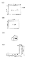
以下、図14〜図16を参照しつつ、分割画像サイズSS及び分割数SNを設定する処理について説明する。ここで、図14は、画像音響制御部140のCPU141によって実行される設定処理の一例を示すフローチャートである。図15は、メイン画像サイズ、サブ画像サイズ、フレームバッファサイズ、及び空き領域のサイズについて説明するための説明図である。図16は、画像音響制御部140のCPU141によって実行される設定処理について説明するための説明図である。なお、図14以降のフローチャートに基づいて説明する画像音響制御部140で行われる処理は、制御用ROM144に記憶されているプログラムに基づいてCPU141が発行する命令に従って行われる。
Hereinafter, the process of setting the divided image size SS and the division number SN will be described with reference to FIGS. Here, FIG. 14 is a flowchart illustrating an example of setting processing executed by the CPU 141 of the image sound control unit 140. FIG. 15 is an explanatory diagram for explaining the main image size, the sub image size, the frame buffer size, and the size of the free area. FIG. 16 is an explanatory diagram for explaining a setting process executed by the CPU 141 of the image sound control unit 140. Note that the processing performed by the image sound control unit 140 described based on the flowcharts of FIG.
例えばパチンコ遊技機1の電源が投入されたときや、液晶表示器5を用いた1画面表示から液晶表示器5及びEL表示器6を用いた2画面表示に切り替えられるとき等に、分割画像サイズSS及び分割数SNの設定処理を指示する設定指示コマンドが演出制御部130から画像音響制御部140へ送信される。これに対して、画像音響制御部140のCPU141は、設定指示コマンドを受信したか否かを判定する(ステップS1)。設定指示コマンドを受信していないとCPU141によって判定された場合(ステップS1:NO)、待機状態となる。
For example, when the power of the pachinko gaming machine 1 is turned on, or when switching from a one-screen display using the liquid crystal display 5 to a two-screen display using the liquid crystal display 5 and the EL display 6, the divided image size A setting instruction command for instructing setting processing of the SS and the number of divisions SN is transmitted from the effect control unit 130 to the image sound control unit 140. On the other hand, the CPU 141 of the image sound control unit 140 determines whether a setting instruction command has been received (step S1). If the CPU 141 determines that the setting instruction command has not been received (step S1: NO), a standby state is entered.
CPU141は、設定指示コマンドを受信したと判定した場合(ステップS1:YES)、メイン画像サイズ、サブ画像サイズ、及びフレームバッファ(FB)サイズを取得する(ステップS2)。具体的には、VDP142から第1フレームバッファ1426A及び第2フレームバッファ1426Bのフレームバッファサイズを取得してRAM145に格納すると共に、液晶画面50の画面解像度及びEL画面60の画面解像度をメイン画像サイズ及びサブ画像サイズとしてVDP142を介して液晶表示器5及びEL表示器6から取得してRAM145に格納する。ここで、フレームバッファサイズは、図15(A)に示されるように、第1フレームバッファ1426A(或いは第2フレームバッファ1426B)に格納可能な画素データの垂直方向11の画素数L1及び水平方向12の画素数C1を示す情報であり、本実施形態では720×960(垂直画素数L1×水平画素数C1)である(図16(A)参照)。メイン画像サイズは、図15(B)に示されるように、メイン画像を構成する画素データの垂直方向11の画素数L2及び水平方向12の画素数C2を示す情報であり、液晶画面50の画面解像度と等しく、本実施形態では600×800(垂直画素数L2×水平画素数C2)である(図16(A)参照)。サブ画像サイズは、図15(C)に示されるように、サブ画像を構成する画素データの垂直方向11の画素数L3及び水平方向12の画素数C3を示す情報であり、EL画面60の画面解像度と等しく、本実施形態では240×320(垂直画素数L3×水平画素数C3)である(図16(C)参照)。
When it is determined that the setting instruction command has been received (step S1: YES), the CPU 141 acquires the main image size, the sub image size, and the frame buffer (FB) size (step S2). Specifically, the frame buffer sizes of the first frame buffer 1426A and the second frame buffer 1426B are acquired from the VDP 142 and stored in the RAM 145, and the screen resolution of the liquid crystal screen 50 and the screen resolution of the EL screen 60 are set to the main image size and The sub image size is acquired from the liquid crystal display 5 and the EL display 6 via the VDP 142 and stored in the RAM 145. Here, as shown in FIG. 15A, the frame buffer size includes the number of pixels L1 in the vertical direction 11 and the horizontal direction 12 of the pixel data that can be stored in the first frame buffer 1426A (or the second frame buffer 1426B). In this embodiment, the information is 720 × 960 (vertical pixel number L1 × horizontal pixel number C1) (see FIG. 16A). As shown in FIG. 15B, the main image size is information indicating the number of pixels L2 in the vertical direction 11 and the number of pixels C2 in the horizontal direction 12 of the pixel data constituting the main image. In this embodiment, the resolution is equal to 600 × 800 (vertical pixel number L2 × horizontal pixel number C2) (see FIG. 16A). As shown in FIG. 15C, the sub image size is information indicating the number of pixels L3 in the vertical direction 11 and the number of pixels C3 in the horizontal direction 12 of the pixel data constituting the sub image. The resolution is equal to 240 × 320 (vertical pixel number L3 × horizontal pixel number C3) in this embodiment (see FIG. 16C).
次に、CPU141は、取得したメイン画像サイズ、及びフレームバッファサイズに基づいて、第1フレームバッファ1426Aにメイン画像を描画した後に生じる空き領域のサイズを算出する(ステップS3)。具体的には、以下の演算式を用いて、空き領域に描画可能な画素データの最低垂直画素数L4(図15(D)参照)、及び最低水平画素数C4(図15(D)参照)を算出する。
最低垂直画素数L4=垂直画素数L1−垂直画素数L2
最低水平画素数C4=水平画素数C1−水平画素数C2
本実施形態では、図16に示されるように、垂直画素数L1が「720」であり、垂直画素数L2が「600」であるため、最低垂直画素数L4として「120」が算出され、水平画素数C1が「960」であり、水平画素数C2が「800」であるため、最低水平画素数C4として「160」が算出される(図16(B)参照)。
Next, the CPU 141 calculates the size of the empty area that occurs after the main image is drawn in the first frame buffer 1426A based on the acquired main image size and frame buffer size (step S3). Specifically, by using the following arithmetic expression, the minimum vertical pixel number L4 (see FIG. 15D) and the minimum horizontal pixel number C4 (see FIG. 15D) of the pixel data that can be drawn in the empty area. Is calculated.
Minimum vertical pixel number L4 = vertical pixel number L1-vertical pixel number L2
Minimum horizontal pixel number C4 = horizontal pixel number C1−horizontal pixel number C2
In the present embodiment, as shown in FIG. 16, since the vertical pixel number L1 is “720” and the vertical pixel number L2 is “600”, “120” is calculated as the minimum vertical pixel number L4, and the horizontal Since the pixel number C1 is “960” and the horizontal pixel number C2 is “800”, “160” is calculated as the minimum horizontal pixel number C4 (see FIG. 16B).
続いて、CPU141は、以下の演算式を用いて、サブ画像を構成する画素データの総数ST、及び空き領域に描画可能な画素データの総数VTを算出し、総数STが総数VTよりも小さいか否かを判定する(ステップS4)。
総数ST=垂直画素数L3×水平画素数C3
総数VT=垂直画素数L4×水平画素数C1+水平画素数C4×(垂直画素数L1−垂直画素数L4)
ここで、垂直画素数L3は、サブ画像を構成する画素データの垂直方向11の画素数であり、水平画素数C3は、サブ画像を構成する画素データの水平方向12の画素数である。総数ST及び総数VTを算出すると、CPU141は、総数STが総数VTよりも小さいか否かを判定する。総数STが総数VTよりも小さければ、サブ画像をそのまま或いは分割して第1フレームバッファ1426Aに描画することができると判断することができる。一方、総数STが総数VTよりも大きければ、サブ画像を分割したとしてもそのままでは第1フレームバッファ1426Aに描画することはできないと判断することができる。
Subsequently, the CPU 141 calculates the total number ST of pixel data constituting the sub-image and the total number VT of pixel data that can be drawn in the empty area using the following arithmetic expression, and whether the total number ST is smaller than the total number VT. It is determined whether or not (step S4).
Total number ST = vertical pixel number L3 × horizontal pixel number C3
Total number VT = vertical pixel number L4 × horizontal pixel number C1 + horizontal pixel number C4 × (vertical pixel number L1−vertical pixel number L4)
Here, the vertical pixel number L3 is the number of pixels in the vertical direction 11 of the pixel data constituting the sub-image, and the horizontal pixel number C3 is the number of pixels in the horizontal direction 12 of the pixel data constituting the sub-image. After calculating the total number ST and the total number VT, the CPU 141 determines whether or not the total number ST is smaller than the total number VT. If the total number ST is smaller than the total number VT, it can be determined that the sub-image can be drawn in the first frame buffer 1426A as it is or divided. On the other hand, if the total number ST is larger than the total number VT, it can be determined that even if the sub-image is divided, it cannot be drawn in the first frame buffer 1426A as it is.
分割判定手段として機能するCPU141は、総数STが総数VTよりも小さいと判定した場合(ステップS4:YES)、サブ画像を空き領域に描画するためにサブ画像を分割する必要があるか否かを判定する(ステップS5)。具体的には、サブ画像を構成する画素データの垂直画素数L3(図15(C)参照)が空き領域の最低垂直画素数L4(図15(D)参照)よりも小さいか、又はサブ画像を構成する画素データの水平画素数C3(図15(C)参照)が空き領域の最低水平画素数C4(図15(D)参照)よりも小さいかの少なくとも一方の条件を満たしているか否かを判定する。ここで、垂直画素数L3が最低垂直画素数L4よりも小さいか、又は水平画素数C3が最低水平画素数C4よりも小さければ、サブ画像を分割することなく空き領域に描画することが可能であると判定することができる。一方、垂直画素数L3が最低垂直画素数L4よりも大きく且つ水平画素数C3が最低水平画素数C4よりも大きい場合、サブ画像を空き領域にそのまま描画できないので、サブ画像を分割して描画する必要があると判定することができる。このように、CPU141は、空き領域のサイズ、及びサブ画像サイズに基づいて、サブ画像の分割の必要性を判定する。
When determining that the total number ST is smaller than the total number VT (step S4: YES), the CPU 141 functioning as the division determination unit determines whether the sub image needs to be divided in order to draw the sub image in the empty area. Determine (step S5). Specifically, the number of vertical pixels L3 (see FIG. 15C) of the pixel data constituting the sub image is smaller than the minimum number of vertical pixels L4 (see FIG. 15D) of the empty area, or the sub image. Whether or not the number of horizontal pixels C3 (see FIG. 15C) of the pixel data constituting the image data is smaller than the minimum number of horizontal pixels C4 in the empty area (see FIG. 15D). Determine. Here, if the number of vertical pixels L3 is smaller than the minimum number of vertical pixels L4 or the number of horizontal pixels C3 is smaller than the minimum number of horizontal pixels C4, it is possible to draw the sub-image in an empty area without dividing it. It can be determined that there is. On the other hand, when the vertical pixel number L3 is larger than the minimum vertical pixel number L4 and the horizontal pixel number C3 is larger than the minimum horizontal pixel number C4, the sub image cannot be drawn as it is in the empty area, so the sub image is divided and drawn. It can be determined that it is necessary. As described above, the CPU 141 determines the necessity of dividing the sub image based on the size of the empty area and the sub image size.
CPU141は、分割が不要であると判定した場合(ステップS5:NO)、分割数SNを「0」に設定する(ステップS6)。ここで、分割数SNは、空き領域に描画される分割画像の数を示す情報である。言い換えれば、分割数SNは、サブ画像を構成する分割画像の数を示す情報である。このステップS6で設定された分割数SNは、設定情報としてRAM145に格納される。この設定情報は、VDP142へ出力される制御信号に含まれて、VDP142へと送られる。後に詳述するが、分割数SNが「0」に設定された場合、空き領域には分割画像が描画されず、サブ画像がそのまま描画されることになる。
When the CPU 141 determines that the division is unnecessary (step S5: NO), the CPU 141 sets the division number SN to “0” (step S6). Here, the division number SN is information indicating the number of divided images drawn in the empty area. In other words, the division number SN is information indicating the number of divided images constituting the sub image. The division number SN set in step S6 is stored in the RAM 145 as setting information. This setting information is included in the control signal output to the VDP 142 and sent to the VDP 142. As will be described in detail later, when the division number SN is set to “0”, the divided image is not drawn in the empty area, and the sub image is drawn as it is.
算出手段として機能するCPU141は、分割が必要であると判定した場合(ステップS5:YES)、空き領域サイズ及びサブ画像サイズに基づいて、分割画像サイズSS及び分割数SNを算出する(ステップS7)。ここで、分割画像サイズSSは、サブ画像が分割数SNで示される個数の分割画像に分割された場合に、1個の分割画像のサイズ(垂直画素数、及び水平画素数)を示す情報である。ステップS7では、以下の演算式を用いて、分割画像サイズSS(分割画像の垂直画素数SSLと分割画像の水平画素数SSC)及び分割数SNを算出する。
分割画像の垂直画素数SSL=最低垂直画素数L4
分割画像の水平画素数SSC=最低水平画素数C4
分割数SN=(垂直画素数L3/最低垂直画素数L4)×(水平画素数C3/最低水平画素数C4)
図16(B)及び(C)に示されるように、本実施形態では、最低垂直画素数L4として「120」が算出され、最低水平画素数C4として「160」が算出される。このため、ここでの分割画像サイズSSは、120×160(垂直画素数SSL×水平画素数SSC)となる。また、分割数SNは、(240/120)×(320/160)により「4」が算出される。
When the CPU 141 functioning as a calculation unit determines that the division is necessary (step S5: YES), the CPU 141 calculates the divided image size SS and the division number SN based on the free area size and the sub image size (step S7). . Here, the divided image size SS is information indicating the size (the number of vertical pixels and the number of horizontal pixels) of one divided image when the sub-image is divided into the number of divided images indicated by the division number SN. is there. In step S7, the divided image size SS (the vertical pixel number SSL of the divided image and the horizontal pixel number SSC of the divided image) and the divided number SN are calculated using the following arithmetic expressions.
The number of vertical pixels of the divided image SSL = the minimum number of vertical pixels L4
The number of horizontal pixels SSC of the divided image = the minimum number of horizontal pixels C4
Number of divisions SN = (vertical pixel number L3 / minimum vertical pixel number L4) × (horizontal pixel number C3 / minimum horizontal pixel number C4)
As shown in FIGS. 16B and 16C, in this embodiment, “120” is calculated as the minimum vertical pixel number L4, and “160” is calculated as the minimum horizontal pixel number C4. Therefore, the divided image size SS here is 120 × 160 (vertical pixel number SSL × horizontal pixel number SSC). The division number SN is calculated as “4” by (240/120) × (320/160).
CPU141は、分割画像サイズSS及び分割数SNを算出した後、算出した分割画像サイズSS及び分割数SNを設定情報としてRAM145に格納する(ステップS8)。この設定情報は、VDP142へ出力される制御信号に含まれて、VDP142へと送られる。なお、ステップS8の設定処理に代えてステップS6の設定処理が行われた場合には、サブ画像を分割する必要がないので分割画像サイズSSは算出されず、設定情報として、分割数SNが「0」であることを示す情報のみがVDP142へ送られる。
After calculating the divided image size SS and the number of divisions SN, the CPU 141 stores the calculated divided image size SS and the number of divisions SN as setting information in the RAM 145 (step S8). This setting information is included in the control signal output to the VDP 142 and sent to the VDP 142. When the setting process of step S6 is performed instead of the setting process of step S8, the divided image size SS is not calculated because there is no need to divide the sub-image, and the division number SN is set as “setting information”. Only information indicating “0” is sent to the VDP 142.
ここで、分割画像サイズSS及び分割数SNを変化させた場合の分割画像サイズSSと空き領域サイズとの関係について図16(C)に基づいて説明する。垂直画素数L3が「240」であり水平画素数C3が「320」であるサブ画像に対して、仮に分割数SNが「0」に設定された場合(ステップS6の処理が行われた場合)、図16(B)及び図16(C)から明らかなように、垂直画素数L3が最低垂直画素数L4を超え且つ水平画素数C3が最低水平画素数C4を超えているので、第1フレームバッファ1426Aの空き領域にサブ画像をそのまま描画することはできない。
Here, the relationship between the divided image size SS and the free area size when the divided image size SS and the number of divisions SN are changed will be described with reference to FIG. When the division number SN is set to “0” for the sub-image having the vertical pixel number L3 of “240” and the horizontal pixel number C3 of “320” (when the process of step S6 is performed). As apparent from FIGS. 16B and 16C, since the number of vertical pixels L3 exceeds the minimum number of vertical pixels L4 and the number of horizontal pixels C3 exceeds the minimum number of horizontal pixels C4, the first frame A sub-image cannot be drawn as it is in the empty area of the buffer 1426A.
また、仮に分割数SNが「2」に設定された場合、サブ画像を垂直画素数が「240」で水平画素数が「160」である2個の分割画像として空き領域に描画する第1の方法と、サブ画像を垂直画素数が「120」で水平画素数が「320」である2個の分割画像として空き領域に描画する第2の方法とが考えられる(図16(C)の真ん中の図を参照)。しかしながら、第1の方法でサブ画像を描画することを考えた場合、空き領域内の垂直方向11に延びる領域(図16(B)参照)に2個の分割画像を描画することは可能であるが、空き領域内の水平方向12に延びる領域に分割画像を描画することはできない。なぜなら、分割画像の垂直画素数「240」が、空き領域の最低垂直画素数L4(=120)を超えているからである。また、第2の方法でサブ画像を描画することを考えた場合、空き領域内の横方向に延びる領域(図16(B)参照)に2個の分割画像を描画することは可能であるが、空き領域内の垂直方向11に延びる領域に2個の分割画像を描画することはできない。なぜなら、分割画像の水平画素数「320」が、空き領域の最低水平画素数C4(=160)を超えているからである。このように、本実施形態で例示したサブ画像を分割画像として空き領域に描画する際に分割数SNを「2」に設定すると、分割画像を描画する位置によっては、分割画像を空き領域に描画できないケースが生じ得る。
Further, if the division number SN is set to “2”, the first sub-image is drawn in the empty area as two divided images having a vertical pixel number of “240” and a horizontal pixel number of “160”. And a second method of drawing the sub-image in the empty area as two divided images having a vertical pixel count of “120” and a horizontal pixel count of “320” (middle of FIG. 16C). (Refer to the figure below.) However, when drawing a sub-image by the first method, it is possible to draw two divided images in a region (see FIG. 16B) extending in the vertical direction 11 in the empty region. However, a divided image cannot be drawn in an area extending in the horizontal direction 12 in the empty area. This is because the number of vertical pixels “240” of the divided image exceeds the minimum number of vertical pixels L4 (= 120) in the empty area. In addition, when considering sub-image drawing by the second method, it is possible to draw two divided images in a region (see FIG. 16B) extending in the horizontal direction in the empty region. Two divided images cannot be drawn in an area extending in the vertical direction 11 in the empty area. This is because the horizontal pixel number “320” of the divided image exceeds the minimum horizontal pixel number C4 (= 160) of the empty area. As described above, when the number of divisions SN is set to “2” when the sub image illustrated in this embodiment is drawn as a divided image in the empty area, the divided image is drawn in the empty area depending on the position where the divided image is drawn. Cases that cannot be done may occur.
これに対して、上述のように分割数SNが「4」に設定された場合、図16(B)及び図16(C)の右側の図から明らかなように、垂直画素数SSLが空き領域の最低垂直画素数L4と同じ「120」に設定され、且つ水平画素数SSCが空き領域の最低水平画素数C4と同じ「160」に設定される。そして、この分割画像サイズSSの分割画像が空き領域に4個描画されることになる。この場合、各分割画像は、空き領域内の垂直方向11に延びる領域と水平方向12に延びる領域とのいずれにも描画可能である。したがって、分割数SNが「2」に設定された場合とは異なり、分割画像を描画する位置によって空き領域に分割画像を描画できないケースが生じることはない。このように、分割数SN及び分割画像サイズSSは、分割画像をどのような配列で空き領域に描画したとしても確実に空き領域に収まるように、適切な値に設定される。
On the other hand, when the number of divisions SN is set to “4” as described above, the vertical pixel number SSL is an empty area, as is apparent from the diagrams on the right side of FIGS. 16B and 16C. Is set to “120” which is the same as the minimum vertical pixel number L4, and the horizontal pixel number SSC is set to “160” which is the same as the minimum horizontal pixel number C4 of the empty area. Then, four divided images of this divided image size SS are drawn in the empty area. In this case, each divided image can be drawn in either the area extending in the vertical direction 11 or the area extending in the horizontal direction 12 in the empty area. Therefore, unlike the case where the division number SN is set to “2”, there is no case where the divided image cannot be drawn in the empty area depending on the position where the divided image is drawn. As described above, the number of divisions SN and the divided image size SS are set to appropriate values so that the divided images can be surely fit in the empty area regardless of the arrangement of the divided images drawn in the empty area.
一方、上記ステップS4において総数STが総数VTよりも大きいとCPU141に判定された場合(ステップS4:NO)、たとえサブ画像を分割したとしても、サブ画像を構成する全ての画素データを空き領域に描画することは不可能である。このため、CPU141は、総数STが総数VTよりも大きいと判定した場合(ステップS4:NO)、縮小倍率を算出して(ステップS9)、算出した縮小倍率を設定情報としてRAM145に格納する(ステップS10)。そして、ステップS7,S8へ処理が進められて、分割画像サイズSS及び分割数SNが設定される。
On the other hand, if the CPU 141 determines that the total number ST is larger than the total number VT in step S4 (step S4: NO), even if the sub-image is divided, all the pixel data constituting the sub-image are set as free areas. It is impossible to draw. Therefore, when the CPU 141 determines that the total number ST is larger than the total number VT (step S4: NO), the CPU 141 calculates a reduction ratio (step S9), and stores the calculated reduction ratio in the RAM 145 as setting information (step S9). S10). Then, the process proceeds to steps S7 and S8, and the divided image size SS and the division number SN are set.
ここで、縮小倍率の設定方法について説明する。例えばステップS9で縮小倍率が「0.5」に設定された場合、垂直画素数L3が「240」であり水平画素数C3が「320」であるサブ画像(図16(C)の左側の図を参照)が、垂直画素数L3が「120」(=240×0.5)であり水平画素数C3が「160」(=320×0.5)であるサブ画像として、ステップS7,S8の処理が行われる。この場合、描画処理に際して、VRAM_RS1425上で垂直方向11及び水平方向12の画素数を1/2にしたサブ画像が生成されて、そのサブ画像が、分割画像サイズSS及び分割数SNに基づく分割画像として第1フレームバッファ1426Aの空き領域に描画されることになる。そして、これらの分割画像は、垂直方向11及び水平方向12の画素数を2倍にするスケーリング処理(拡大処理)が描画エンジン1424によって行われてからEL表示器6へ出力される。これにより、分割したとしても空き領域に描画できないサブ画像を空き領域に描画することが可能になる。したがって、空き領域サイズに対して画面解像度が大きい画像表示器を備えるパチンコ遊技機において、従来の描画処理ではその画像表示器に画像を表示することができないという問題を、分割画像サイズSS及び分割数SNに加えて縮小倍率を設定することで解決することができる。
Here, a method for setting the reduction ratio will be described. For example, when the reduction ratio is set to “0.5” in step S9, the sub-image (the figure on the left side of FIG. 16C) in which the vertical pixel number L3 is “240” and the horizontal pixel number C3 is “320”. As a sub-image having a vertical pixel number L3 of “120” (= 240 × 0.5) and a horizontal pixel number C3 of “160” (= 320 × 0.5), steps S7 and S8 are performed. Processing is performed. In this case, in the rendering process, a sub image in which the number of pixels in the vertical direction 11 and the horizontal direction 12 is halved is generated on the VRAM_RS 1425, and the sub image is a divided image based on the divided image size SS and the division number SN. Are drawn in the empty area of the first frame buffer 1426A. These divided images are output to the EL display 6 after scaling processing (enlargement processing) for doubling the number of pixels in the vertical direction 11 and the horizontal direction 12 is performed by the drawing engine 1424. This makes it possible to draw a sub-image that cannot be drawn in the empty area even if it is divided, in the empty area. Therefore, in a pachinko gaming machine having an image display device having a large screen resolution with respect to the free space size, the problem that the conventional drawing process cannot display an image on the image display device is that the divided image size SS and the number of divisions. This can be solved by setting a reduction ratio in addition to SN.
なお、縮小倍率は、例えば縮小後のサブ画像の総画素数(=垂直画素数×水平画素数)が、空き領域に描画可能な画素データの総数VT以下(好ましくは総数VTより所定数以上小さい値)となるように設定すればよい。これにより、サブ画像を分割画像として空き領域に描画することが可能となる。ただし、縮小倍率を小さくし過ぎると、スケーリング処理の結果としてEL表示器6に表示される画像の画質が低下するおそれがあるので、縮小倍率は、縮小後のサブ画像の総画素数が総数VTを超えない範囲で、できるだけ大きな値に設定することが好ましい。
Note that the reduction magnification is such that, for example, the total number of sub-images after reduction (= the number of vertical pixels × the number of horizontal pixels) is less than or equal to the total number VT of pixel data that can be drawn in a free area (preferably smaller than the total number VT by a predetermined number or more) Value). This makes it possible to draw the sub image as a divided image in the empty area. However, if the reduction ratio is too small, the image quality of the image displayed on the EL display 6 as a result of the scaling process may be deteriorated. Therefore, the reduction ratio is set so that the total number of pixels of the sub-image after reduction is the total number VT. It is preferable to set the value as large as possible within a range not exceeding.
以上説明した図14のフローチャートに基づく設定処理が行われることにより、第1フレームバッファ1426Aへのメイン画像及びサブ画像の描画に際してサブ画像の縮小が必要か否かを示す情報、縮小が必要な場合には縮小倍率、サブ画像の分割が必要か否かを示す情報、分割が必要な場合には分割画像サイズSS及び分割数SN(分割数SN=0の場合は分割数SNのみ)が、設定情報としてRAM145に格納される。後述する描画エンジン1424による2画面表示のための描画処理は、この設定情報に基づいて実行される。
When the setting process based on the flowchart of FIG. 14 described above is performed, information indicating whether or not the sub image needs to be reduced when the main image and the sub image are drawn in the first frame buffer 1426A, and the case where the reduction is necessary Is set with a reduction ratio, information indicating whether or not sub-image division is necessary, and a division image size SS and a division number SN (when the division number SN = 0, only the division number SN) is set. Information is stored in the RAM 145 as information. Drawing processing for two-screen display by the drawing engine 1424 described later is executed based on this setting information.
CPU141は、液晶表示器5のみを用いた1画面表示を実行する際には、上記設定処理によってRAM145に格納した設定情報を含まない制御信号をVDP142へ出力する。これにより、VRAM_FB1426にメイン画像のみが描画されて、液晶表示器5のみを用いた1画面表示が行われる。一方、液晶表示器5及びEL表示器6を用いた2画面表示を実行する際には、CPU141は、設定情報を含む制御信号をVDP142へ出力する。これにより、VRAM_FB1426にメイン画像及びサブ画像が描画されて、液晶表示器5及びEL表示器6を用いた2画面表示が行われる。このように、CPU141が設定情報を含まない制御信号と設定情報を含む制御信号とを切り換えて出力することにより、VDP142が描画処理を適切に行うことができる。また、上記設定処理が行われることにより、例えばEL表示器6のリユースによってEL画面60の画面解像度、すなわちサブ画像サイズが変化した場合でも、第1フレームバッファ1426A又は第2フレームバッファ1426Bの空き領域へのサブ画像の描画を適切に行うことができる。
When executing a one-screen display using only the liquid crystal display 5, the CPU 141 outputs a control signal that does not include the setting information stored in the RAM 145 by the setting process to the VDP 142. As a result, only the main image is drawn on the VRAM_FB 1426, and a one-screen display using only the liquid crystal display 5 is performed. On the other hand, when executing two-screen display using the liquid crystal display 5 and the EL display 6, the CPU 141 outputs a control signal including setting information to the VDP 142. As a result, the main image and the sub image are drawn on the VRAM_FB 1426, and the two-screen display using the liquid crystal display 5 and the EL display 6 is performed. In this way, the CPU 141 can appropriately perform the drawing process by switching and outputting the control signal not including the setting information and the control signal including the setting information. Further, by performing the setting process, for example, even when the screen resolution of the EL screen 60, that is, the sub image size changes due to reuse of the EL display 6, the first frame buffer 1426A or the second frame buffer 1426B has a free space. It is possible to appropriately draw the sub-image.
[遊技制御部100の主要動作]
次に、遊技制御部100において行われる主要動作について説明する。図17は、遊技制御部100によって行われる主要動作の一例を示すフローチャートである。遊技制御部100は、電源投入時や電源断時等の特殊な場合を除く通常の動作時において、図17に示されている一連の処理を一定時間(例えば4ミリ秒)毎に繰り返し実行する。なお、図17以降のフローチャートに基づいて説明する遊技制御部100の処理は、ROM102に記憶されているプログラムに基づいてCPU101が発行する命令に従って行われる。
[Main operations of game control unit 100]
Next, main operations performed in the game control unit 100 will be described. FIG. 17 is a flowchart illustrating an example of main operations performed by the game control unit 100. The game control unit 100 repeatedly executes a series of processes shown in FIG. 17 every predetermined time (for example, 4 milliseconds) in a normal operation except for a special case such as when the power is turned on or when the power is turned off. . Note that the processing of the game control unit 100 described based on the flowcharts from FIG.
乱数更新処理(ステップS11)では、遊技制御部100は、大当たり乱数、図柄乱数、リーチ乱数、変動パターン乱数、及び普通図柄乱数の各種の乱数の更新を行う。ここで、大当たり乱数は、特別図柄抽選の当選(大当たり或いは小当たり)又は落選(ハズレ)を決定するための乱数である。図柄乱数は、特別図柄抽選に当選した場合に、当たりの種類(長当たり、短当たり、高確率状態への移行の有無、時短遊技状態への移行の有無)を決定するための乱数である。リーチ乱数は、特別図柄抽選に落選した場合に、リーチ有りの演出を行うか或いはリーチ無しの演出を行うかを決定するための乱数である。変動パターン乱数は、特別図柄が変動表示される際の変動パターンを決定するための乱数である。普通図柄乱数は、普通図柄抽選の当選又は落選を決定するための乱数である。大当たり乱数、図柄乱数、リーチ乱数、変動パターン乱数、及び普通図柄乱数は、このステップS11の処理が行われる毎に「1」ずつ加算される。そして、各抽選が行われた時点の値がステップS12の始動口スイッチ(SW)処理やステップS13のゲートスイッチ(SW)処理で取得され、ステップS14の特別図柄処理やステップS15の普通図柄処理で使用される。なお、このステップS1の処理を行うカウンタにはループカウンタが使用されており、設定されている乱数の最大値に達した後は、再び「0」に戻る。
In the random number update process (step S11), the game control unit 100 updates various random numbers such as a jackpot random number, a symbol random number, a reach random number, a variation pattern random number, and a normal symbol random number. Here, the big hit random number is a random number for determining the winning (big hit or small hit) or the loss (losing) of the special symbol lottery. The symbol random number is a random number for determining a winning type (long hit, short hit, presence / absence of transition to a high probability state, presence / absence of transition to a short-time gaming state) when a special symbol lottery is won. The reach random number is a random number for determining whether to perform an effect with reach or an effect without reach when the special symbol lottery is lost. The variation pattern random number is a random number for determining a variation pattern when a special symbol is displayed in a variable manner. The normal symbol random number is a random number for determining whether the normal symbol lottery is won or lost. The jackpot random number, the design random number, the reach random number, the variation pattern random number, and the normal design random number are incremented by “1” every time the process of step S11 is performed. Then, the values at the time each lottery is performed are acquired by the start switch (SW) process in step S12 or the gate switch (SW) process in step S13, and in the special symbol process in step S14 or the normal symbol process in step S15. used. Note that a loop counter is used as the counter for performing the processing of step S1, and after reaching the set maximum value of the random number, it returns to “0” again.
始動口スイッチ(SW)処理(ステップS12)では、遊技制御部100は、第1始動口スイッチ111及び第2始動口スイッチ112の状態を監視し、いずれかのスイッチから検出信号が出力された場合に、第1特別図柄抽選の保留数U1や第2特別図柄抽選の保留数U2に関する処理や乱数(大当たり乱数、図柄乱数、リーチ乱数、及び変動パターン乱数)を取得する処理等を実行する。この始動口スイッチ処理の詳細については、図19に基づいて後に詳述する。
In the start port switch (SW) process (step S12), the game control unit 100 monitors the states of the first start port switch 111 and the second start port switch 112, and a detection signal is output from either switch. In addition, a process related to the hold number U1 for the first special symbol lottery and the hold number U2 for the second special symbol lottery, a process for obtaining random numbers (a jackpot random number, a symbol random number, a reach random number, and a variation pattern random number) are executed. Details of the start port switch process will be described later with reference to FIG.
ゲートスイッチ(SW)処理(ステップS13)では、遊技制御部100は、ゲートスイッチ114の状態を監視し、遊技球がゲート25を通過してゲートスイッチ114から検出信号が出力された場合に、普通図柄抽選の保留数が上限値未満であるか否かを判断する。そして、保留数が上限値未満であると判断した場合に、ステップS15の普通図柄処理に使用される普通図柄乱数を取得する。
In the gate switch (SW) process (step S13), the game control unit 100 monitors the state of the gate switch 114. When the game ball passes through the gate 25 and a detection signal is output from the gate switch 114, it is normal. It is determined whether or not the number of symbols in the lottery is less than the upper limit. Then, when it is determined that the number of holds is less than the upper limit value, a normal symbol random number used for the normal symbol processing in step S15 is acquired.
特別図柄処理(ステップS14)では、遊技制御部100は、特別図柄抽選を実行し、液晶表示器5に特別図柄を変動表示してから特別図柄抽選の結果を示す特別図柄を停止表示するための処理を実行する。この特別図柄処理については、図22に基づいて後に詳述する。
In the special symbol process (step S14), the game control unit 100 executes the special symbol lottery, displays the special symbol on the liquid crystal display 5 variably, and then stops and displays the special symbol indicating the result of the special symbol lottery. Execute the process. This special symbol process will be described in detail later based on FIG.
普通図柄処理(ステップS15)では、遊技制御部100は、ステップS13のゲートスイッチ処理で取得された普通図柄乱数がその当選値と一致するか否かを判定する。そして、表示器4の普通図柄表示器45(図3参照)に普通図柄を変動表示させた後に判定結果を示す普通図柄を停止表示させる。
In the normal symbol process (step S15), the game control unit 100 determines whether or not the normal symbol random number acquired in the gate switch process in step S13 matches the winning value. Then, after the normal symbol is variably displayed on the normal symbol display 45 (see FIG. 3) of the display device 4, the normal symbol indicating the determination result is stopped and displayed.
大入賞口処理(ステップS16)では、遊技制御部100は、特別図柄抽選に当選した場合に、大入賞口制御部116を介して大入賞口23の開閉を制御する。
In the special prize opening process (step S16), the game control unit 100 controls the opening / closing of the special prize opening 23 via the special prize opening control unit 116 when the special symbol lottery is won.
電動チューリップ処理(ステップS17)では、遊技制御部100は、ステップS15の普通図柄処理において普通図柄乱数がその当選値と一致すると判定された場合に、電動チューリップ開閉部113を介して電動チューリップ27の一対の羽根部材を作動させる。電動チューリップ27が作動することによって第2始動口22へ遊技球が入賞可能な状態となり、第2始動口22に遊技球が入賞することで第2特別図柄抽選が始動する。
In the electric tulip process (step S17), the game control unit 100 determines that the electric tulip 27 of the electric tulip 27 via the electric tulip opening / closing unit 113 when it is determined in the normal symbol process in step S15 that the normal symbol random number matches the winning value. A pair of blade members is operated. When the electric tulip 27 is operated, a game ball can be awarded to the second start port 22, and when the game ball wins the second start port 22, the second special symbol lottery is started.
賞球処理(ステップS18)では、遊技制御部100は、上述したように、遊技球の入賞個数の管理及び入賞に応じた賞球の払い出しを制御する。
In the prize ball process (step S18), as described above, the game control unit 100 controls the number of game balls won and controls the payout of prize balls according to the prize.
出力処理(ステップS19)では、遊技制御部100は、ステップS12の始動口スイッチ処理やステップS14の特別図柄処理等でRAM103にセットされた各種コマンドや演出に必要な情報を演出制御部130へ送る。また、ステップS18の賞球処理でRAM103にセットされた賞球の払い出しを指示するコマンドを払出制御部120へ送る。
In the output process (step S19), the game control unit 100 sends to the effect control unit 130 various commands set in the RAM 103 and information necessary for the effect in the start port switch process in step S12 and the special symbol process in step S14. . In addition, a command instructing the payout of the prize ball set in the RAM 103 in the prize ball processing in step S18 is sent to the payout control unit 120.
[遊技制御部100のRAM103の構成]
次に、遊技制御部100のRAM103の構成について説明する。図18は、遊技制御部100のRAM103の構成例を示すブロック図である。図18(A)はRAM103の記憶領域109及び保留数記憶部110の構成を示し、図18(B)は記憶領域109を構成する各記憶部109A〜109Hの構成を示している。
[Configuration of RAM 103 of Game Control Unit 100]
Next, the configuration of the RAM 103 of the game control unit 100 will be described. FIG. 18 is a block diagram illustrating a configuration example of the RAM 103 of the game control unit 100. 18A shows the configuration of the storage area 109 and the reserved number storage unit 110 of the RAM 103, and FIG. 18B shows the configuration of the storage units 109A to 109H constituting the storage area 109.
図18(A)に示されるように、RAM103は、記憶領域109及び保留数記憶部110を有している。記憶領域109は、パチンコ遊技機1において保留可能な最大8個の保留球に対する大当たり乱数等をそれぞれ記憶するために、第1記憶部109A、第2記憶部109B、第3記憶部109C、第4記憶部109D、第5記憶部109E、第6記憶部109F、第7記憶部109G、及び第8記憶部109Hから構成されている。
As illustrated in FIG. 18A, the RAM 103 includes a storage area 109 and a reserved number storage unit 110. The storage area 109 stores, for example, a jackpot random number or the like for up to eight reserved balls that can be held in the pachinko gaming machine 1, a first storage unit 109A, a second storage unit 109B, a third storage unit 109C, a fourth The storage unit 109D, the fifth storage unit 109E, the sixth storage unit 109F, the seventh storage unit 109G, and the eighth storage unit 109H are configured.
これらの記憶部109A〜109Hは、図18(B)に示されるように、それぞれ、変動回数Nを記憶する領域、入賞始動口情報を記憶する領域、大当たり乱数を記憶する領域、図柄乱数を記憶する領域、リーチ乱数を記憶する領域、変動パターン乱数を記憶する領域、及び事前判定情報を記憶する領域を含んでいる。
As shown in FIG. 18B, these storage units 109A to 109H each store an area for storing the number of fluctuations N, an area for storing winning start information, an area for storing jackpot random numbers, and a design random number. A region for storing a reach random number, a region for storing a variation pattern random number, and a region for storing pre-determination information.
変動回数Nは、第1始動口21又は第2始動口22に遊技球が入賞して獲得した特別図柄抽選の権利の合計回数を示す情報である。例えば、パチンコ遊技機1の電源が投入されてから、第1始動口21に遊技球が入賞して第1特別図柄抽選の権利を50回獲得し、第2始動口22に遊技球が入賞して第2特別図柄抽選の権利を10回獲得した場合、変動回数Nとして、これらの権利の回数を足し合わせた「60」が例えば第3記憶部109Cに記憶される。そして、この状態から更に第1始動口21に遊技球が入賞して特別図柄抽選の権利を獲得すると、「60」に「1」を加算した「61」が変動回数Nとして第4記憶部109Dに記憶される。
The number of times of change N is information indicating the total number of special symbol lottery rights acquired by winning the game ball in the first start port 21 or the second start port 22. For example, after the power of the pachinko gaming machine 1 is turned on, a game ball wins the first starting slot 21 to acquire the first special symbol drawing right 50 times, and a game ball wins the second starting slot 22 When the right of the second special symbol lottery is acquired 10 times, “60”, which is the sum of the numbers of these rights, is stored in the third storage unit 109C, for example, as the number of changes N. Then, when the game ball wins further at the first starting port 21 from this state and acquires the right of special symbol lottery, “61”, which is obtained by adding “1” to “60”, is set as the number N of times of change, and the fourth storage unit 109D. Is remembered.
なお、第1始動口21に入賞した遊技球の保留数が最大保留数Umax1(本実施形態では「4」)に達した状態で第1始動口21に新たな遊技球が入賞した場合には、変動回数Nはカウントされず、大当たり乱数等も記憶領域109に記憶されない。また、第2始動口22に入賞した遊技球の保留数が最大保留数Umax2(本実施形態では「4」)に達した状態で第2始動口22に新たな遊技球が入賞した場合にも、変動回数Nはカウントされず、大当たり乱数等の記憶領域109に記憶されない。
In the case where a new game ball wins at the first start port 21 in a state where the number of hold of the game ball won at the first start port 21 reaches the maximum hold number Umax1 (“4” in the present embodiment). The number of fluctuations N is not counted, and a big hit random number or the like is not stored in the storage area 109. In addition, even when a new game ball wins the second start port 22 in a state where the hold number of the game balls won in the second start port 22 reaches the maximum hold number Umax2 (“4” in this embodiment). The number of fluctuations N is not counted and is not stored in the storage area 109 such as a big hit random number.
入賞始動口情報は、同じ記憶部内に格納されている大当たり乱数、図柄乱数、リーチ乱数、及び変動パターン乱数が、遊技球が第1始動口21に入賞したことを契機として取得されたのか、或いは遊技球が第2始動口22に入賞したことを契機として取得されたのかを示す情報である。これらの大当たり乱数、図柄乱数、リーチ乱数、及び変動パターン乱数については後に詳述する。
The winning start information is obtained when the jackpot random number, the design random number, the reach random number, and the variation pattern random number stored in the same storage unit are obtained when the game ball wins the first starting port 21 or This is information indicating whether or not the game ball has been acquired when the second starting port 22 is won. These jackpot random numbers, design random numbers, reach random numbers, and variation pattern random numbers will be described in detail later.
事前判定情報は、大当たり乱数、図柄乱数、リーチ乱数、及び変動パターン乱数に基づいて、後述する事前判定処理(図21参照)で得られる情報である。事前判定情報は、具体的には、入賞始動口情報、特別図柄抽選の結果が大当たり、小当たり、及びハズレのいずれであるのかを示す情報、大当たりであった場合にはその大当たりの種類が何であるかを示す情報、小当たりであった場合にはその小当たりの種類が何であるかを示す情報、ハズレであった場合には演出内容はリーチ有り演出であるのかリーチ無し演出であるのかを示す情報、特別図柄の変動パターン(変動時間)を示す情報、パチンコ遊技機1の遊技状態を示す情報を含む。事前判定情報は、事前判定情報を生成するための基となった大当たり乱数、図柄乱数、リーチ乱数、変動パターン乱数等と同じ記憶部内に記憶される。
The pre-determination information is information obtained by a pre-determination process (see FIG. 21) described later based on the jackpot random number, the design random number, the reach random number, and the variation pattern random number. Specifically, the pre-judgment information is information indicating whether the winning start information, the special symbol lottery result is a big win, a small win, or a loss. Information indicating whether there is a small hit, information indicating what the type of the small hit is, if it is a loss, whether the production content is a production with reach or a production without reach Information indicating the variation pattern (variation time) of the special symbol, and information indicating the gaming state of the pachinko gaming machine 1 are included. The advance determination information is stored in the same storage unit as the jackpot random number, the design random number, the reach random number, the variation pattern random number, and the like that are the basis for generating the advance determination information.
図18(B)に示されている変動回数N、入賞始動口情報、大当たり乱数、図柄乱数、リーチ乱数、変動パターン乱数、及び事前判定情報の7つの情報は、第1始動口21又は第2始動口22に遊技球が入賞する毎に、第1記憶部109Aから順に記憶される。例えば第1記憶部109A〜第8記憶部109Hのいずれにも情報が記憶されていない場合、7つの情報は、第1記憶部109Aに記憶される。また、例えば第1記憶部109A〜第4記憶部109Dのそれぞれに7つの情報が既に記憶されている場合、新たに取得された7つの情報は、第5記憶部109Eに記憶されることとなる。また、第1記憶部109Aに記憶されている乱数を取得する契機となった保留球が消化される際に、第1記憶部109Aに記憶されている7つの情報が破棄されると共に、各記憶部に記憶されている情報をシフトさせる処理が行われる。例えば、第1記憶部109A〜第3記憶部109Cにそれぞれ7つの情報が記憶されている状態で第1記憶部109Aに記憶されている情報に対応する保留球が消化された場合、第1記憶部109Aに記憶されている情報が破棄され、第2記憶部109Bに記憶されている情報が第1記憶部109Aへ移動され、第3記憶部109Cに記憶されている情報が第2記憶部109Bへ移動される。
The seven types of information shown in FIG. 18B, the number of times of change N, the winning start information, the jackpot random number, the design random number, the reach random number, the change pattern random number, and the pre-determination information, Every time a game ball wins at the start port 22, the first storage unit 109A sequentially stores the game balls. For example, when no information is stored in any of the first storage unit 109A to the eighth storage unit 109H, seven pieces of information are stored in the first storage unit 109A. For example, when seven pieces of information are already stored in each of the first storage unit 109A to the fourth storage unit 109D, the seven pieces of newly acquired information are stored in the fifth storage unit 109E. . In addition, when the reserved ball that triggered the acquisition of the random number stored in the first storage unit 109A is digested, the seven pieces of information stored in the first storage unit 109A are discarded and each storage A process for shifting the information stored in the unit is performed. For example, in the case where seven pieces of information are stored in each of the first storage unit 109A to the third storage unit 109C, when the reserved ball corresponding to the information stored in the first storage unit 109A is digested, the first storage unit The information stored in unit 109A is discarded, the information stored in second storage unit 109B is moved to first storage unit 109A, and the information stored in third storage unit 109C is the second storage unit 109B. Moved to.
図18(A)に示される保留数記憶部110には、第1特別図柄抽選の保留数U1、第2特別図柄抽選の保留数U2、及び普通図柄抽選の保留数が記憶されている。保留数U1は、第1始動口21に遊技球が入賞したタイミング、又は第1特別図柄抽選が行われるタイミングでCPU101によって適宜更新される。保留数U2は、第2始動口22に遊技球が入賞したタイミング、又は第2特別図柄抽選が行われるタイミングでCPU101によって適宜更新される。普通図柄抽選の保留数は、遊技球がゲート25を通過したタイミング、又は普通図柄抽選が行われるタイミングでCPU101によって適宜更新される。
The number-of-holds storage unit 110 shown in FIG. 18A stores the number of held U1 for the first special symbol lottery, the number of held U2 for the second special symbol lottery, and the number of held for the normal symbol lottery. The holding number U1 is appropriately updated by the CPU 101 at the timing when a game ball wins the first start port 21 or at the timing when the first special symbol lottery is performed. The number of holds U2 is appropriately updated by the CPU 101 at the timing when a game ball wins the second start port 22 or when the second special symbol lottery is performed. The holding number of the normal symbol lottery is appropriately updated by the CPU 101 at the timing when the game ball passes the gate 25 or the timing when the normal symbol lottery is performed.
[遊技制御部100による始動口スイッチ処理]
図19は、図17のステップS12における始動口スイッチ処理の詳細フローチャートである。遊技制御部100のCPU101は、図19に示されるように、第1始動口スイッチ111からの検出信号の有無に基づいて、第1始動口21に遊技球が入賞して第1始動口スイッチ111が「ON」になったか否かを判定する(ステップS121)。第1始動口スイッチ111が「ON」になったとCPU101によって判定された場合(ステップS121:YES)、CPU101は、第1特別図柄抽選の最大保留数Umax1をROM102から読み出し、保留数記憶部110に記憶されている第1特別図柄抽選の保留数U1が最大保留数Umax1未満であるか否かを判定する(ステップS122)。
[Start-up switch processing by game control unit 100]
FIG. 19 is a detailed flowchart of the start port switch process in step S12 of FIG. As shown in FIG. 19, the CPU 101 of the game control unit 100 receives a game ball in the first start port 21 based on the presence / absence of a detection signal from the first start port switch 111 and the first start port switch 111. Is determined to be "ON" (step S121). When the CPU 101 determines that the first start port switch 111 has been turned “ON” (step S121: YES), the CPU 101 reads out the maximum holding number Umax1 of the first special symbol lottery from the ROM 102, and stores it in the holding number storage unit 110. It is determined whether or not the stored number U1 of the first special symbol lottery is less than the maximum number of reservations Umax1 (step S122).
CPU101は、保留数U1が最大保留数Umax1未満であると判定した場合(ステップS122:YES)、保留数記憶部110に記憶されている保留数U1の値を「1」加算して更新する(ステップS123)。そして、記憶領域109に新たに記憶される変動回数Nを「1」加算する(ステップS124)。
When the CPU 101 determines that the hold number U1 is less than the maximum hold number Umax1 (step S122: YES), the CPU 101 updates the value of the hold number U1 stored in the hold number storage unit 110 by adding “1” (step S122: YES). Step S123). Then, “1” is added to the number of fluctuations N newly stored in the storage area 109 (step S124).
CPU101は、第1始動口21を示す入賞始動口情報、及びステップS124の処理で更新した変動回数Nと共に、ステップS123の処理によって保留した第1特別図柄抽選のための乱数(大当たり乱数、図柄乱数、リーチ乱数、及び変動パターン乱数)を取得して、記憶領域109に格納する(ステップS125)。そして、CPU101は、ステップS125の処理で記憶領域109に格納された乱数を用いて、後述する事前判定処理を行う(ステップS126)。
The CPU 101 receives the winning start opening information indicating the first starting opening 21 and the number of fluctuations N updated in the process of step S124, along with the random numbers for the first special symbol lottery held by the process of step S123 (big hit random numbers, symbol random numbers). , Reach random number, and fluctuation pattern random number) are acquired and stored in the storage area 109 (step S125). Then, the CPU 101 performs a pre-determination process to be described later using the random number stored in the storage area 109 in the process of step S125 (step S126).
第1始動口スイッチ111が「OFF」であると判定された場合(ステップS121:NO)、保留数U1が最大保留数Umax1と等しいと判定された場合(ステップS122:NO)、又はステップS126の事前判定処理が行われた場合、CPU101は、第2始動口スイッチ112からの検出信号の有無に基づいて、第2始動口22に遊技球が入賞して第2始動口スイッチ112が「ON」になったか否かを判定する(ステップS127)。CPU101は、第2始動口スイッチ112が「ON」になったと判定した場合(ステップS127:YES)、第2特別図柄抽選の最大保留数Umax2をROM102から読み出し、保留数記憶部110に記憶されている第2特別図柄抽選の保留数U2が最大保留数Umax2未満であるか否かを判定する(ステップS128)。
When it is determined that the first start port switch 111 is “OFF” (step S121: NO), when it is determined that the hold number U1 is equal to the maximum hold number Umax1 (step S122: NO), or in step S126 When the pre-determination process is performed, based on the presence or absence of a detection signal from the second start port switch 112, the CPU 101 wins a game ball in the second start port 22 and the second start port switch 112 is “ON”. It is determined whether or not (step S127). When the CPU 101 determines that the second start port switch 112 has been turned “ON” (step S127: YES), the CPU 101 reads the maximum reserved number Umax2 of the second special symbol lottery from the ROM 102, and is stored in the reserved number storage unit 110. It is determined whether or not the holding number U2 of the second special symbol lottery is less than the maximum holding number Umax2 (step S128).
CPU101は、保留数U2が最大保留数Umax2未満であると判定した場合(ステップS128:YES)、保留数記憶部110に記憶されている保留数U2の値を「1」加算して更新する(ステップS129)。そして、記憶領域109に新たに記憶される変動回数Nを「1」加算する(ステップS130)。
When the CPU 101 determines that the hold number U2 is less than the maximum hold number Umax2 (step S128: YES), the CPU 101 updates the value of the hold number U2 stored in the hold number storage unit 110 by adding “1” (step S128: YES). Step S129). Then, “1” is added to the number of fluctuations N newly stored in the storage area 109 (step S130).
CPU101は、第2始動口22を示す入賞始動口情報、及びステップS130の処理で更新した変動回数Nと共に、ステップS129の処理によって保留した第2特別図柄抽選のための乱数(大当たり乱数、図柄乱数、リーチ乱数、及び変動パターン乱数)を取得して、記憶領域109に格納する(ステップS131)。そして、CPU101は、ステップS131の処理で記憶領域109に格納された乱数を用いて事前判定処理を行う(ステップS132)。このステップS132における事前判定処理は、ステップS126における事前判定処理と同様に行われる。
The CPU 101 receives the winning start opening information indicating the second starting opening 22 and the number of fluctuations N updated in the process of step S130, as well as the random numbers (big hit random numbers, symbol random numbers) for the second special symbol lottery held by the process of step S129. , Reach random number, and fluctuation pattern random number) are acquired and stored in the storage area 109 (step S131). Then, the CPU 101 performs a pre-determination process using the random number stored in the storage area 109 in the process of step S131 (step S132). The advance determination process in step S132 is performed in the same manner as the advance determination process in step S126.
一方、第2始動口スイッチ112が「OFF」であると判定された場合(ステップS127:NO)、保留数U2が最大保留数Umax2と等しいと判定された場合(ステップS128:NO)、又はステップS132の事前判定処理が行われた場合、始動口スイッチ処理が終了して、図17のステップS13におけるゲートスイッチ処理へ処理が進められる。
On the other hand, when it is determined that the second start port switch 112 is “OFF” (step S127: NO), when it is determined that the hold number U2 is equal to the maximum hold number Umax2 (step S128: NO), or step When the advance determination process of S132 is performed, the start port switch process ends, and the process proceeds to the gate switch process in step S13 of FIG.
[乱数による判定方法]
次に、事前判定処理(図21参照)や後述するステップS147(図22参照)の大当たり判定処理での乱数による判定方法について説明する。図20は、事前判定処理や大当たり判定処理に使用される乱数の構成例を示す図である。図20(A)は、大当たり乱数の一例を示している。図20(B)は、第1始動口入賞による大当たり時の図柄乱数の一例を示し、図20(C)は、第2始動口入賞による大当たり時の図柄乱数の一例を示し、図20(D)は小当たり時の図柄乱数の一例を示している。図20(E)は、リーチ乱数の一例を示している。
[Judgment method using random numbers]
Next, a determination method using random numbers in the advance determination process (see FIG. 21) and the jackpot determination process in step S147 (see FIG. 22) described later will be described. FIG. 20 is a diagram illustrating a configuration example of random numbers used in the advance determination process and the jackpot determination process. FIG. 20A shows an example of a jackpot random number. FIG. 20B shows an example of a design random number at the time of jackpot due to the first start opening prize, FIG. 20C shows an example of a design random number at the time of jackpot by the second start opening prize, FIG. ) Shows an example of a design random number at the time of small hit. FIG. 20E shows an example of a reach random number.
図20(A)に示されるように、大当たり乱数は、パチンコ遊技機1が特別図柄抽選の当選確率が相対的に低い低確率状態である場合と高確率状態である場合とのそれぞれについて、個別に設定されている。大当たり乱数の取り得る範囲は、いずれの遊技状態においても「0」〜「600」である。また、大当たり乱数は、低確率状態と高確率状態のそれぞれについて、大当たりのときと小当たりのときの2種類が設定されている。すなわち、乱数判定テーブルとして、低確率状態での大当たり乱数の判定に用いられる低確率時乱数判定テーブルと、高確率状態での大当たり乱数の判定に用いられる高確率時乱数判定テーブルとが用意されている。
As shown in FIG. 20 (A), the jackpot random number is different for each of the cases where the pachinko gaming machine 1 is in a low probability state and a high probability state where the winning probability of the special symbol lottery is relatively low. Is set to The range that the jackpot random number can take is “0” to “600” in any gaming state. In addition, two types of jackpot random numbers are set for each of a low probability state and a high probability state, that is, a jackpot and a jackpot. That is, as a random number determination table, a low probability random number determination table used for determining a jackpot random number in a low probability state and a high probability random number determination table used for determining a jackpot random number in a high probability state are prepared. Yes.
低確率状態に関して、大当たり当選値が2個(「7」と「317」)設定されているので、低確率状態での大当たり当選確率は2/601であり、低確率状態のときに取得された大当たり乱数が「7」又は「317」である場合に大当たりと判定される。低確率状態に関して、小当たり当選値が2個(「50」と「100」)設定されているので、低確率状態での小当たり当選確率は2/601であり、低確率状態のときに取得された大当たり乱数が「50」又は「100」である場合に小当たりと判定される。
As for the low probability state, two jackpot winning values (“7” and “317”) are set, so the jackpot winning probability in the low probability state is 2/601, which was acquired in the low probability state When the jackpot random number is “7” or “317”, the jackpot is determined. Regarding the low-probability state, two small winning winning values (“50” and “100”) are set, so the small-winning winning probability in the low-probability state is 2/601, which is acquired in the low-probability state. When the hit jackpot random number is “50” or “100”, it is determined as a jackpot.
高確率状態に関して、大当たり当選値が20個(「7」,「37」,「67」,・・・,「517」,「547」,「577」)設定されており、高確率状態での大当たり当選確率は20/601である。高確率状態で取得された大当たり乱数がこれら20個の当選値のいずれかと一致した場合に、大当たりと判定される。高確率状態に関して、小当たり当選値が2個(「50」と「100」)設定されているので、高確率状態での小当たり当選確率は2/601であり、高確率状態の時に取得された大当たり乱数が「50」又は「100」である場合に小当たりと判定される。
With regard to the high probability state, 20 jackpot winning values (“7”, “37”, “67”,..., “517”, “547”, “577”) are set. The jackpot winning probability is 20/601. If the jackpot random number acquired in the high probability state matches any of these 20 winning values, the jackpot is determined. With respect to the high probability state, two small winning values (“50” and “100”) are set, so the small winning winning probability in the high probability state is 2/601, which is acquired in the high probability state. When the big hit random number is “50” or “100”, it is determined that the jackpot is a small hit.
ここで、「小当たり」は、小当たりと判定された場合に例えば大入賞口23の開閉が2回行われる小当たり遊技が実行され、小当たり当選時の遊技状態が小当たり遊技終了後も継続する当たりである。このため、小当たり当選時の遊技状態が例えば確変遊技状態であった場合、遊技状態が移行せずに小当たり遊技終了後も確変遊技状態が継続される。また、小当たり当選時の遊技状態が例えば通常遊技状態であった場合、遊技状態が移行せずに小当たり遊技終了後も通常遊技状態が継続される。
Here, when “small hit” is determined to be a small hit, for example, a small hit game in which the opening / closing of the big winning opening 23 is performed twice is executed, and the game state at the time of winning the small hit is also after the small hit game ends. It is a hit. For this reason, if the gaming state at the time of winning the small hit is, for example, the probability variation gaming state, the gaming state is not shifted and the probability variation gaming state is continued even after the end of the small hitting game. Also, if the gaming state at the time of winning the small hit is, for example, the normal gaming state, the gaming state does not shift and the normal gaming state is continued even after the small hitting game ends.
一方の大当たりに関して、本実施形態では、低確率状態に対する大当たり当選値が「2」個設定されているのに対して、高確率状態に対する大当たり当選値が「20」個設定されている。このため、高確率状態で第1始動口21又は第2始動口22に遊技球が入賞して特別図柄抽選が行われて大当たりとなる確率は、低確率状態で第1始動口21又は第2始動口22に遊技球が入賞して特別図柄抽選が行われて大当たりとなる確率の10倍となっている。
With respect to one jackpot, in this embodiment, “2” jackpot winning values for the low probability state are set, whereas “20” jackpot winning values for the high probability state are set. For this reason, the probability that the game ball wins the first start port 21 or the second start port 22 in the high probability state and the special symbol lottery is performed and the big win is the first start port 21 or the second in the low probability state. The game ball is won at the starting port 22 and a special symbol lottery is performed, which is ten times the probability of winning a jackpot.
第1特別図柄抽選の結果が大当たりであった場合、以下のような図柄乱数に関する判定処理が行われる。図20(B)に示されるように、第1始動口入賞による大当たりの種類として、高確率時短付き長当たり、通常時短付き長当たり、高確率時短付き短当たり、通常時短付き短当たり、高確率時短無し長当たり、及び通常時短無し短当たりの6種類が用意されている。第1始動口21に遊技球が入賞した際に取得される図柄乱数の取り得る範囲は、「0」〜「250」である。高確率時短付き長当たりに関して、「0」〜「100」の101個の当選値が割り当てられているので、101/251の確率で高確率時短付き長当たりとなる。また、通常時短付き長当たりに関して、「101」〜「150」の50個の当選値が割り当てられているので、50/251の確率で通常時短付き長当たりとなる。また、高確率時短付き短当たり、通常時短付き短当たり、高確率時短無し長当たり、及び通常時短無し短当たりに関しては、「151」〜「175」,「176」〜「200」,「201」〜「225」,「226」〜「250」の当選値がそれぞれ割り当てられているので、いずれの当たりについてもその確率は25/251である。
When the result of the first special symbol lottery is a big hit, the following determination process regarding the symbol random number is performed. As shown in FIG. 20 (B), the types of jackpots based on the first start opening prize are as follows: per length with high probability, short per length, short per length with high probability, short per short with high probability, short per short with normal time, high probability There are six types available, one for each short time and one for normal and one for short time. The range that can be taken by the design random number acquired when a game ball wins the first starting port 21 is “0” to “250”. Since 101 winning values of “0” to “100” are assigned per length with high probability, the length per length with high probability is 101/251. Further, since 50 winning values of “101” to “150” are assigned per length with a normal time shortening, it is per length with a normal time shortening with a probability of 50/251. In addition, “151” to “175”, “176” to “200”, “201” for short per short with high probability, per short with normal time, per short length with high probability, and per short without normal time. Since the winning values of “225” and “226” to “250” are respectively assigned, the probability is 25/251 for any winning.
第2特別図柄抽選の結果が大当たりであった場合、以下のような図柄乱数に関する判定処理が行われる。図20(C)に示されるように、第2始動口入賞による大当たりの種類として、高確率時短付き長当たり、及び通常時短付き長当たりの2種類が用意されている。第2始動口22に遊技球が入賞した際に取得される図柄乱数の取り得る範囲は、「0」〜「250」である。高確率時短付き長当たりに関して、「0」〜「150」の151個の当選値が割り当てられているので、151/251の確率で高確率時短付き長当たりとなる。通常時短付き長当たりに関して、「151」〜「250」の100個の当選値が割り当てられているので、100/251の確率で通常時短付き長当たりとなる。
When the result of the second special symbol lottery is a big hit, the following determination process regarding the symbol random number is performed. As shown in FIG. 20C, there are two types of jackpots for the second start-up winnings, one per length with a high probability and a length with a normal time. The possible range of symbol random numbers acquired when a game ball wins the second starting port 22 is “0” to “250”. Since 151 winning values of “0” to “150” are assigned per length with high probability, the length per length with high probability is 151/251. Since 100 winning values of “151” to “250” are assigned per length with a normal time / short time, it is per length with a normal time / short with a probability of 100/251.
上述したように、第1始動口21又は第2始動口22へ遊技球が入賞した際に取得された大当たり乱数が「50」又は「100」である場合、小当たりと判定される。図20(D)に示されるように、小当たりの種類として、小当たりA、及び小当たりBの2種類が用意されている。小当たり時の図柄乱数の範囲は、「0」〜「250」である。小当たりAに関して、「0」〜「120」の121個の当選値が割り当てられているので、121/251の確率で小当たりAとなる。一方の小当たりBに関して、「121」〜「250」の130個の当選値が割り当てられているので、130/251の確率で小当たりBとなる。なお、小当たりA及び小当たりBは、その後に実行される小当たり遊技の内容は全く同じであり、表示器4の第1特別図柄表示器41又は第2特別図柄表示器42に表示される特別図柄のみが相違する。
As described above, if the big hit random number acquired when the game ball wins the first start opening 21 or the second start opening 22 is “50” or “100”, it is determined that the big hit. As shown in FIG. 20D, two types of small hits A and small hits B are prepared as the types of small hits. The range of the design random number at the time of small hit is “0” to “250”. With respect to the small hit A, 121 winning values of “0” to “120” are assigned, so the small hit A has a probability of 121/251. With respect to one small hit B, since 130 winning values of “121” to “250” are assigned, the small hit B is 130/251. Note that the small hit A and the small hit B have the same contents of the small hit game executed thereafter, and are displayed on the first special symbol display 41 or the second special symbol display 42 of the display 4. Only the special symbol is different.
特別図柄抽選の結果がハズレであった場合、以下のようなリーチ乱数に関する判定処理が行われる。図20(E)に示されるように、リーチ乱数の取り得る範囲は「0」〜「250」であり、リーチ有りの場合とリーチ無しの場合のそれぞれについてリーチ乱数判定テーブルが用意されている。リーチ有りに関しては、「0」〜「24」の25個のリーチ乱数が割り当てられているので、25/251の確率でリーチとなる。また、リーチ無しに関しては、「25」〜「250」の226個のリーチ乱数が割り当てられているので、226/251の確率でリーチ無しとなる。さらに説明すると、特別図柄抽選の結果がハズレである(図20(A)に示されているいずれの当選値にも該当しない)と判定された場合にのみ、リーチ乱数判定テーブルに基づいてリーチ乱数の判定が行われる。そして、上述したように、ハズレ時には、リーチ無しの演出が実行される確率が高くなる一方で、遊技者に期待感を与えるいわゆるガセリーチ演出が10%程度の確率で実行されることとなる。その一方で、大当たり時及び小当たり時には必ずリーチ有り演出が実行されるため、この場合にはリーチ乱数は取得されるもののリーチ乱数に関する判定は行われない。
When the result of the special symbol lottery is a loss, the following determination process regarding reach random numbers is performed. As shown in FIG. 20E, the reachable range of reach random numbers is “0” to “250”, and a reach random number determination table is prepared for each of the cases with and without reach. Regarding reach, since 25 reach random numbers “0” to “24” are assigned, reach is achieved with a probability of 25/251. Further, with respect to the absence of reach, 226 reach random numbers “25” to “250” are assigned, and therefore no reach is achieved with a probability of 226/251. More specifically, the reach random number is determined based on the reach random number determination table only when it is determined that the result of the special symbol lottery is a loss (does not correspond to any winning value shown in FIG. 20A). Is determined. As described above, at the time of losing, the probability that an effect without reach is increased, while a so-called gas reasure effect that gives a player a sense of expectation is executed with a probability of about 10%. On the other hand, since the reach presence effect is always executed at the time of big hit and small hit, in this case, the reach random number is acquired, but the determination on the reach random number is not performed.
なお、大当たりに当選した場合には、リーチ有り演出が必ず行われて、最終的に横又は斜めにわたる一直線上に同一の数字が3つ揃った状態の特別図柄が特別図柄抽選の結果として液晶画面50に表示される。これに対して、小当たりに当選した場合やハズレの場合のリーチ有り演出は、一直線上に同一の数字が2つだけ揃って3つ目は揃わない状態で特別図柄が停止表示される。
In the case of winning the jackpot, there will always be a production with reach, and finally a special symbol with three identical numbers on a horizontal or diagonal line will be displayed on the LCD screen as a result of the special symbol lottery. 50. On the other hand, in the case of winning with a small win or loss, the special symbol is stopped and displayed in a state where only two identical numbers are aligned on the straight line and the third is not aligned.
[遊技制御部100による事前判定処理]
以下、図21を参照しつつ、遊技制御部100によって行われる事前判定処理について説明する。ここで、図21は、図19のステップS126,S132における事前判定処理の詳細フローチャートである。
[Preliminary determination processing by game control unit 100]
Hereinafter, the prior determination process performed by the game control unit 100 will be described with reference to FIG. Here, FIG. 21 is a detailed flowchart of the preliminary determination process in steps S126 and S132 of FIG.
図19におけるステップS125の処理又はステップS131の処理が行われた後、遊技制御部100のCPU101は、RAM103に記憶されている遊技状態情報に基づいて、パチンコ遊技機1の遊技状態が高確率状態(本実施形態では確変遊技状態又は潜伏遊技状態)であるか否かを判定する(ステップS1261)。CPU101は、高確率状態であると判定した場合(ステップS1261:YES)、始動口スイッチ処理で取得した特別図柄抽選の権利が、現在の高確率状態に移行してから、何回目の特別図柄抽選の権利に相当するものであるのかを判定する。すなわち、遊技状態が高確率状態となる大当たり(高確率時短付き長当たり、高確率時短付き短当たり、又は高確率時短無し短当たり)の当選が確定すると、大当たりに当選した際の変動回数Nが、基準回数Mに設定される。例えば、パチンコ遊技機1の電源が投入されてから200回目の特別図柄抽選によって、例えば高確率時短付き長当たりに当選した場合には、RAM103に「200」というデータが記憶され、それに伴って、内部状態が高確率状態となる。したがって、パチンコ遊技機1の電源投入から201回目に行われる特別図柄抽選は、高確率状態に移行してから1回目の特別図柄抽選に相当し、210回目に行われる特別図柄抽選は、高確率状態に移行してから10回目の特別図柄抽選に相当することとなる。このように、始動口スイッチ処理によって取得された特別図柄抽選の権利が、高確率状態に移行してから何回目の特別図柄抽選に相当するのかを演算する。具体的には、CPU101は、変動回数Nから基準回数Mを減算して演算値Lを求める(ステップS1262)。
After the process of step S125 or the process of step S131 in FIG. 19 is performed, the CPU 101 of the game control unit 100 determines that the gaming state of the pachinko gaming machine 1 is in a high probability state based on the gaming state information stored in the RAM 103. It is determined whether or not it is a probability variation gaming state or a latent gaming state in this embodiment (step S1261). When the CPU 101 determines that the state is a high probability state (step S1261: YES), the special symbol lottery number of times after the right of the special symbol lottery acquired by the start-up switch process shifts to the current high probability state. It is determined whether it is equivalent to the right. In other words, if the winning of the jackpot (per length with high probability short-time, short per short with high probability short-time or short per short without high-probability time short) is determined when the gaming state becomes a high probability state, the number of changes N when winning the jackpot is The reference number M is set. For example, in the case of winning by the special symbol lottery of the 200th time since the power of the pachinko gaming machine 1 is turned on, for example, per winning length with high probability, data “200” is stored in the RAM 103, and accordingly, The internal state becomes a high probability state. Therefore, the special symbol lottery performed at the 201st time since the power-on of the pachinko gaming machine 1 corresponds to the first special symbol lottery after shifting to the high probability state, and the special symbol lottery performed at the 210th time is a high probability. This corresponds to the 10th special symbol lottery after the transition to the state. In this way, the special symbol lottery right acquired by the start port switch process is calculated to correspond to the number of special symbol lotteries after the transition to the high probability state. Specifically, the CPU 101 subtracts the reference number M from the variation number N to obtain the calculated value L (step S1262).
そして、CPU101は、演算値Lが所定回数X以下であるか否かを判定する(ステップS1263)。ここで、所定回数Xは、高確率時乱数判定テーブル(図20(A)参照)に基づいて大当たり乱数が判定される上限回数である。本実施形態では、遊技状態が高確率状態となる大当たりに当選すると、それ以降の大当たり乱数の判定が100回を上限として、高確率時乱数判定テーブルに基づいて行われる。したがって、所定回数Xは、本実施形態では「100」に設定されている。このため、本実施形態では、ステップS1263において、CPU101は、演算値Lが「100」以下であるか否かを判定する。すなわち、始動口スイッチ処理によって取得された大当たり乱数が、高確率時乱数判定テーブルに基づいて判定されるのか、或いは、高確率状態が終了して低確率時乱数判定テーブルに基づいて判定されるのかが、このステップS1263で判定される。
Then, the CPU 101 determines whether or not the calculated value L is equal to or less than the predetermined number X (step S1263). Here, the predetermined number X is an upper limit number of times that the big hit random number is determined based on the high probability random number determination table (see FIG. 20A). In the present embodiment, when a jackpot where the gaming state becomes a high probability state is won, the subsequent jackpot random number determination is performed based on the high probability random number determination table with the upper limit being 100 times. Accordingly, the predetermined number X is set to “100” in the present embodiment. Therefore, in the present embodiment, in step S1263, the CPU 101 determines whether or not the calculated value L is “100” or less. That is, whether the jackpot random number acquired by the start port switch process is determined based on the high probability random number determination table, or whether the high probability state ends and is determined based on the low probability random number determination table Is determined in step S1263.
例えば、パチンコ遊技機1の電源が投入されてから200回目の特別図柄抽選(変動回数N=200)によって高確率時短付き短当たりに当選したと仮定する。その後、高確率状態になってから98回目の特別図柄抽選が実行され、未だ大当たりに当選していない状態で、変動回数N=299の保留A、変動回数N=300の保留B、変動回数N=301の保留Cに関する情報が、それぞれ記憶領域109に記憶されたとする。この場合、基準回数Mは「200」に設定されているため、保留Aに対する演算値Lは「99」となり、保留Bに対する演算値Lは「100」となり、保留Cに対する演算値Lは「101」となる。したがって、保留A及び保留BについてはステップS1263で「YES」と判定され、保留CについてはステップS1263で「NO」と判定される。
For example, it is assumed that the short win with a high probability time is won by the 200th special symbol lottery (the number of fluctuations N = 200) after the power of the pachinko gaming machine 1 is turned on. After that, the 98th special symbol lottery is executed after becoming a high probability state, and the variation number N = 299 hold A, the variation number N = 300 hold B, the variation number N in a state where the jackpot has not been won yet. It is assumed that information regarding the hold C = 301 is stored in the storage area 109. In this case, since the reference number M is set to “200”, the calculated value L for the hold A is “99”, the calculated value L for the hold B is “100”, and the calculated value L for the hold C is “101”. " Accordingly, the hold A and the hold B are determined as “YES” in step S1263, and the hold C is determined as “NO” in step S1263.
CPU101は、演算値Lが所定回数X以下であると判定した場合(ステップS1263:YES)、以後の遊技状態を低確率状態に変更する大当たりに係る事前判定情報が始動口スイッチ処理の開始前に記憶領域109に記憶されているか否かを判定する(ステップS1264)。例えば、始動口スイッチ処理のステップS125(図19参照)において第5記憶部109E(図18参照)に乱数を記憶した場合、第1記憶部109Aから第4記憶部109Dに、通常時短付き長当たり、通常時短付き短当たり、通常時短無し短当たりのいずれかに係る事前判定情報が記憶されているか否かを判定する。すなわち、始動口スイッチ処理において保留された保留球よりも先に消化される保留球に、遊技状態を高確率状態から低確率状態へ移行させるものがあるか否かを判断する。なぜなら、このような保留球が先に保留されている場合には、始動口スイッチ処理で保留球が保留されたときには高確率状態であったとしても、その保留球を消化するときには低確率状態になってしまうからである。したがって、CPU101は、先の保留に通常当たりはないと判定した場合には(ステップS1264:NO)、高確率時乱数判定テーブルを選択し(ステップS1266)、先の保留に通常当たりがあると判定した場合には(ステップS1264:YES)、低確率時乱数判定テーブルを選択する(ステップS1267)。
When the CPU 101 determines that the calculated value L is equal to or smaller than the predetermined number of times X (step S1263: YES), the prior determination information related to the jackpot for changing the subsequent gaming state to the low probability state is displayed before the start port switch process is started. It is determined whether or not it is stored in the storage area 109 (step S1264). For example, when a random number is stored in the fifth storage unit 109E (see FIG. 18) in step S125 (see FIG. 19) of the start port switch process, the first storage unit 109A stores the random number in the fourth storage unit 109D. Then, it is determined whether or not pre-determination information relating to either the normal short / short short hit or the normal short / short short hit is stored. That is, it is determined whether or not there is a holding ball that is digested prior to the holding ball that is held in the start-up switch processing, so that the gaming state is shifted from the high probability state to the low probability state. Because, when such a holding ball is put on hold first, even if it is in a high probability state when the holding ball is put on hold in the start-up switch processing, it is in a low probability state when digesting the holding ball. Because it becomes. Therefore, when the CPU 101 determines that the previous hold is not normally hit (step S1264: NO), the CPU 101 selects the high-probability random number determination table (step S1266) and determines that the previous hold has a normal hit. If so (step S1264: YES), the low probability random number determination table is selected (step S1267).
一方、パチンコ遊技機1の現在の遊技状態が低確率状態(通常遊技状態又は時短遊技状態)である場合(ステップS1261:NO)、又は演算値Lが所定回数Xを超えている場合(ステップS1263:NO)、CPU101は、以後の遊技状態を高確率状態に変更する大当たりに係る事前判定情報が始動口スイッチ処理の開始前に記憶領域109に記憶されているか否かを判定する(ステップS1265)。例えば、始動口スイッチ処理のステップS125(図19参照)において第6記憶部109F(図18参照)に乱数を記憶した場合、第1記憶部109Aから第5記憶部109Eに高確率時短付き長当たり、高確率時短付き短当たり、高確率時短無し短当たりのいずれかに係る事前判定情報が記憶されているか否かを判定する。すなわち、始動口スイッチ処理において保留された保留球よりも先に消化される保留球に、遊技状態を低確率状態から高確率状態へ移行させるものがあるか否かを判断する。なぜなら、このような保留球が先に保留されている場合には、始動口スイッチ処理で保留球が保留されたときには低確率状態であったとしても、その保留球を消化するときには高確率状態になってしまうからである。したがって、CPU101は、先の保留に高確率当たりはないと判定した場合には(ステップS1265:NO)、低確率時乱数判定テーブルを選択し(ステップS1267)、先の保留に高確率当たりがあると判定した場合には(ステップS1265:YES)、高確率時乱数判定テーブルを選択する(ステップS1266)。
On the other hand, when the current gaming state of the pachinko gaming machine 1 is a low probability state (normal gaming state or short-time gaming state) (step S1261: NO), or when the calculated value L exceeds the predetermined number X (step S1263) : NO), the CPU 101 determines whether or not the prior determination information relating to the jackpot for changing the subsequent gaming state to the high probability state is stored in the storage area 109 before the start port switch process is started (step S1265). . For example, when a random number is stored in the sixth storage unit 109F (see FIG. 18) in step S125 (see FIG. 19) of the start port switch process, the first storage unit 109A to the fifth storage unit 109E per length with high probability shortening Then, it is determined whether or not pre-determination information related to either a short hit with a high probability short time or a short hit without a high probability short time is stored. That is, it is determined whether or not there is a holding ball that is digested prior to the holding ball that is held in the start-up switch process, and that shifts the gaming state from the low probability state to the high probability state. Because, when such a holding ball is put on hold first, even if it is in a low probability state when the holding ball is put on hold by the start-up switch processing, it is in a high probability state when digesting the holding ball. Because it becomes. Therefore, if the CPU 101 determines that the previous hold does not have a high probability (step S1265: NO), the CPU 101 selects the low probability random number determination table (step S1267), and the previous hold has a high probability. (Step S1265: YES), the high probability random number determination table is selected (step S1266).
なお、記憶領域109(図18参照)に、以後の遊技状態を高確率状態に変更する大当たりに係る事前判定情報と、以後の遊技状態を低確率状態に変更する大当たりに係る事前判定情報とが記憶されている場合、これら2つの事前判定情報のうち、後に消化される保留球に対応する事前判定情報に基づいて、ステップS1264又はステップS1265の処理を行う。例えば、第1記憶部109Aに高確率時短付き長当たりに係る事前判定情報が記憶され、第3記憶部109Cに通常時短付き長当たりに係る事前判定情報が記憶されている場合、第3記憶部109Cに記憶されている事前判定情報に基づいて判定が行われる。この例に対して、ステップS1264の処理が行われる場合には「YES」と判定され、ステップS1265の処理が行われる場合には「NO」と判定される。
In addition, in the storage area 109 (see FIG. 18), prior determination information related to a jackpot for changing a subsequent gaming state to a high probability state and prior determination information related to a jackpot for changing a subsequent gaming state to a low probability state are stored. If stored, the process of step S1264 or step S1265 is performed based on the preliminary determination information corresponding to the reserved ball to be digested later among these two preliminary determination information. For example, when the first storage unit 109A stores pre-determined information related to the length with a high probability of shortening the time, and the third storage unit 109C stores pre-determined information related to the length of the normal time-shortened length, the third storage unit Determination is performed based on the prior determination information stored in 109C. In contrast to this example, “YES” is determined when the process of step S1264 is performed, and “NO” is determined when the process of step S1265 is performed.
このように、ステップS1261〜ステップS1265の処理を行うことで、遊技球が第1始動口21又は第2始動口22に入賞したときのパチンコ遊技機1の内部状態ではなく、特別図柄処理時(保留球消化時)の内部状態に基づいて、遊技球が第1始動口21又は第2始動口22に入賞したときに大当たりの事前判定を行うことが可能となる。したがって、保留球消化前に、高確率状態から低確率状態へと遊技状態が変化する場合や、逆に低確率状態から高確率状態へと遊技状態が変化する場合にも、正確な大当たり(特別図柄抽選)の事前判定結果を導き出すことができる。
In this way, by performing the processing of step S1261 to step S1265, not the internal state of the pachinko gaming machine 1 when the game ball wins the first starting port 21 or the second starting port 22, but during the special symbol processing ( Based on the internal state (at the time of holding ball digestion), it becomes possible to make a jackpot pre-determination when the game ball wins the first start port 21 or the second start port 22. Therefore, even if the gaming state changes from the high probability state to the low probability state before the reservation ball digestion, or conversely, the gaming state changes from the low probability state to the high probability state, It is possible to derive a preliminary determination result of symbol lottery).
ステップS1266又はステップS1267の処理に続き、CPU101は、高確率時乱数判定テーブル及び低確率時乱数判定テーブルのうち、選択したテーブルに基づいて、各乱数の判定を行う(ステップS1268)。具体的には、CPU101は、ステップS125又はステップS131の処理で取得された大当たり乱数が、ステップS1266又はステップS1267の処理で選択された乱数判定テーブル(図20(A)参照)に基づいて、特別図柄抽選の結果が大当たり、小当たり、及びハズレのいずれであるかを判定する。CPU101は、大当たりであると判定した場合にはその大当たりの種類を、大当たり乱数と同じ記憶部に格納された図柄乱数、及び乱数判定テーブル(図20(B)及び図20(C)参照)に基づいて判定する。また、小当たりであると判定した場合には、その小当たりの種類を、図柄乱数及び乱数判定テーブル(図20(D)参照)に基づいて判定する。一方、大当たり乱数が、図20(A)の高確率時乱数判定テーブル及び低確率時乱数判定テーブルに格納されている乱数値(当選値)のいずれにも該当せずにハズレと判定した場合、CPU101は、大当たり乱数及び図柄乱数と同じ記憶部に格納されたリーチ乱数、及び乱数判定テーブル(図20(E)参照)に基づいて、ハズレと判定した遊技球に対する特別図柄の変動表示中にリーチ有りの演出を行うのか或いはリーチ無しの演出を行うのかを判定する。
Following the processing of step S1266 or step S1267, the CPU 101 determines each random number based on the selected table among the high probability random number determination table and the low probability random number determination table (step S1268). Specifically, the CPU 101 determines that the jackpot random number acquired in step S125 or step S131 is based on the random number determination table (see FIG. 20A) selected in step S1266 or step S1267. It is determined whether the symbol lottery result is a big hit, a small win, or a loss. When the CPU 101 determines that the jackpot is a jackpot, the type of jackpot is stored in a symbol random number stored in the same storage unit as the jackpot random number and a random number determination table (see FIGS. 20B and 20C). Judgment based on. In addition, when it is determined that the game is a small hit, the type of the small hit is determined based on the design random number and the random number determination table (see FIG. 20D). On the other hand, when the jackpot random number is determined to be lost without corresponding to any of the random value (winning value) stored in the high probability random number determination table and the low probability random number determination table of FIG. Based on the reach random number stored in the same storage unit as the jackpot random number and the symbol random number, and the random number determination table (see FIG. 20E), the CPU 101 reaches during the special symbol variation display for the game ball determined to be lost. It is determined whether to perform an effect with or without reach.
ところで、図19の表記から明らかなように、本実施形態における事前判定処理は、特別図柄の変動表示が開始されるときではなく、第1始動口21又は第2始動口22に遊技球が入賞したときに行われる。すなわち、CPU101は、遊技球の入賞を検出したタイミングで特別図柄抽選を実行し、上述のように、大当たりと判定した場合にはその大当たりの種類を判定し、小当たりと判定した場合にはその小当たりの種類を判定し、ハズレと判定した場合にはリーチ有り演出を行うか或いはリーチ無し演出を行うかを判定する。そして、大当たり乱数、図柄乱数、及びリーチ乱数と同じ記憶部に格納された変動パターン乱数に基づいて、保留球消化時に液晶表示器5に変動表示される特別図柄の変動パターンを判定する。
By the way, as is clear from the notation of FIG. 19, the prior determination process in the present embodiment is not when the special symbol variation display is started, but the game ball wins at the first start port 21 or the second start port 22. Is done when. That is, the CPU 101 executes a special symbol lottery at the timing when a winning of a game ball is detected, and determines the type of jackpot if it is determined to be a jackpot as described above, and if it determines that the jackpot is determined, The type of small hit is determined, and when it is determined that the game is lost, it is determined whether an effect with reach or an effect without reach is performed. Based on the variation pattern random number stored in the same storage unit as the jackpot random number, the design random number, and the reach random number, the variation pattern of the special design that is variably displayed on the liquid crystal display 5 when the reserved ball is digested is determined.
続いて、CPU101は、ステップS1268の判定の結果を示す情報等を含む事前判定情報を生成する(ステップS1269)。この事前判定情報は、記憶領域109において、ステップS1268の判定で使用した大当たり乱数、図柄乱数、リーチ乱数、及び変動パターン乱数が記憶されているのと同じ記憶部内に格納される。
Subsequently, the CPU 101 generates pre-determination information including information indicating the determination result in step S1268 (step S1269). This prior determination information is stored in the storage unit 109 in the same storage unit in which the jackpot random number, symbol random number, reach random number, and variation pattern random number used in the determination in step S1268 are stored.
事前判定情報を生成した後、CPU101は、演出制御部130に対して液晶表示器5への保留表示画像の追加表示を指示するために、ステップS1269の処理で生成された事前判定情報を含む保留コマンドをRAM103にセット(格納)する(ステップS1270)。この保留コマンドは、CPU101が図17のステップS19における出力処理を実行することによって演出制御部130へ送信される。
After generating the advance determination information, the CPU 101 includes the advance determination information generated in the process of step S1269 in order to instruct the effect control unit 130 to additionally display the hold display image on the liquid crystal display 5. The command is set (stored) in the RAM 103 (step S1270). The hold command is transmitted to the effect control unit 130 when the CPU 101 executes the output process in step S19 of FIG.
後に詳述するが、演出制御部130は、この事前判定情報を含む保留コマンドに基づいて、保留表示画像を液晶表示器5に追加表示する処理を画像音響制御部140に実行させたり、保留球消化時に大当たりとなる信頼度が高いことを予告する演出である先読み演出を画像音響制御部140及びランプ制御部150に実行させる。
As will be described in detail later, the effect control unit 130 causes the image sound control unit 140 to execute a process of additionally displaying the hold display image on the liquid crystal display 5 based on the hold command including the prior determination information, The image sound control unit 140 and the lamp control unit 150 are caused to execute a pre-reading effect, which is an effect of notifying that the reliability that is a big hit at the time of digestion is high.
[遊技制御部100による特別図柄処理]
図22は、図17のステップS14における特別図柄処理の詳細フローチャートである。図22に示されるように、遊技制御部100のCPU101は、RAM103に記憶されている情報に基づいて、パチンコ遊技機1の現在の状態が大当たり中であるか否かを判定する(ステップS141)。大当たり中であるとCPU101によって判定された場合(ステップS141:YES)、既に何らかの大当たりを表す特別図柄が選択されて停止表示されている状態であるため、特別図柄の変動表示を開始することなく特別図柄処理を終了し、ステップS15(図17参照)の普通図柄処理へ処理が進められる。
[Special symbol processing by game control unit 100]
FIG. 22 is a detailed flowchart of the special symbol process in step S14 of FIG. As shown in FIG. 22, the CPU 101 of the game control unit 100 determines whether or not the current state of the pachinko gaming machine 1 is a big hit based on information stored in the RAM 103 (step S141). . If it is determined by the CPU 101 that the jackpot is being hit (step S141: YES), the special symbol representing some jackpot has already been selected and stopped and displayed. The symbol process is terminated, and the process proceeds to the normal symbol process in step S15 (see FIG. 17).
CPU101は、大当たり中ではないと判定した場合(ステップS141:NO)、特別図柄の変動表示中であるか否かを判定する(ステップS142)。CPU101は、特別図柄の変動表示中ではないと判定した場合(ステップS142:NO)、保留数記憶部110(図18(A)参照)に記憶されている保留数U2が「1」以上であるか否かを判定する(ステップS143)。CPU101は、保留数U2が「1」以上であると判定した場合(ステップS143:YES)、保留数記憶部110に記憶されている保留数U2を「1」減算した値に書き換える(ステップS144)。
If the CPU 101 determines that the jackpot is not being won (step S141: NO), the CPU 101 determines whether or not the special symbol is being changed (step S142). When the CPU 101 determines that the special symbol variation display is not being performed (step S142: NO), the number of holds U2 stored in the number-of-holds storage unit 110 (see FIG. 18A) is “1” or more. Is determined (step S143). When the CPU 101 determines that the hold number U2 is “1” or more (step S143: YES), the CPU 101 rewrites the hold number U2 stored in the hold number storage unit 110 to a value obtained by subtracting “1” (step S144). .
CPU101は、保留数U2が「1」以上ではない(第2特別図柄抽選が保留されていない)と判定した場合(ステップS143:NO)、保留数記憶部110に記憶されている保留数U1が「1」以上であるか否かを判定する(ステップS145)。CPU101は、保留数U1が「1」以上であると判定した場合(ステップS145:YES)、保留数記憶部110に記憶されている保留数U1を「1」減算した値に書き換える(ステップS146)。一方、保留数U1が「1」以上ではない(第1特別図柄抽選が保留されていない)とCPU101によって判定された場合(ステップS145:NO)、特別図柄の変動表示を開始することなく特別図柄処理を終了し、ステップS15の普通図柄処理へ処理が進められる。
When the CPU 101 determines that the hold number U2 is not equal to or greater than “1” (the second special symbol lottery is not held) (step S143: NO), the hold number U1 stored in the hold number storage unit 110 is It is determined whether or not “1” or more (step S145). When the CPU 101 determines that the hold number U1 is “1” or more (step S145: YES), the CPU 101 rewrites the hold number U1 stored in the hold number storage unit 110 to a value obtained by subtracting “1” (step S146). . On the other hand, when the CPU 101 determines that the number of held U1 is not equal to or greater than “1” (the first special symbol lottery is not held) (step S145: NO), the special symbol is not started without starting the variable symbol display. The process ends, and the process proceeds to the normal symbol process in step S15.
CPU101は、ステップS144又はステップS146の処理を行った後、大当たり判定処理を実行する(ステップS147)。具体的には、ステップS144の処理に続いてこのステップS147の処理を実行する場合、ROM102に記憶されている大当たりの当選値(図20(A)参照)をRAM103に読み出す。そして、第2始動口22への遊技球の入賞を契機として取得されて記憶領域109(図18参照)に記憶された大当たり乱数の中で最も古い大当たり乱数(最初に記憶された大当たり乱数)が、いずれかの大当たりの当選値と一致するか否かに基づいて、第2特別図柄抽選の結果が大当たり、小当たり、又はハズレのいずれであるかを判定する。
The CPU 101 executes jackpot determination processing after performing the processing of step S144 or step S146 (step S147). Specifically, when the process of step S147 is executed following the process of step S144, the winning value (see FIG. 20A) stored in the ROM 102 is read into the RAM 103. Then, the oldest jackpot random number (the first jackpot random number stored first) among the jackpot random numbers acquired in response to the winning of the game ball at the second starting port 22 and stored in the storage area 109 (see FIG. 18) is Whether the result of the second special symbol lottery is a jackpot, a jackpot or a loss is determined based on whether or not it matches any of the jackpot winning values.
一方、ステップS146の処理に続いてステップS147の処理を実行する場合、CPU101は、ROM102に記憶されている大当たりの当選値(図20(A)参照)をRAM103に読み出す。そして、第1始動口21への遊技球の入賞を契機として取得されて記憶領域109(図18参照)に記憶された大当たり乱数の中で最も古い大当たり乱数(最初に記憶された大当たり乱数)が、いずれかの大当たりの当選値と一致するか否かに基づいて、第1特別図柄抽選の結果が大当たり、小当たり、又はハズレのいずれであるかを判定する。
On the other hand, when the process of step S147 is executed following the process of step S146, the CPU 101 reads the jackpot winning value (see FIG. 20A) stored in the ROM 102 into the RAM 103. Then, the oldest jackpot random number (the first jackpot random number stored first) among the jackpot random numbers acquired in response to the winning of the game ball at the first start port 21 and stored in the storage area 109 (see FIG. 18) is obtained. Whether the result of the first special symbol lottery is a jackpot, a jackpot or a loss is determined based on whether or not it matches any of the jackpot winning values.
第2特別図柄抽選又は第1特別図柄抽選の結果が大当たりであると判定した場合、CPU101は、ROM102から複数種の大当たりのそれぞれに割り当てられた図柄乱数の当選値(図20(B)及び(C)参照)をRAM103に読み出す。そして、大当たりであると判定した抽選に使用した大当たり乱数と同じ記憶部内に記憶されている図柄乱数が、どの図柄乱数の当選値と一致するかに基づいて、大当たりの種類を判定する。その際、第2特別図柄抽選の結果が大当たりであると判定した場合には図20(C)に例示された当選値を用いて大当たりの種類を判定し、第1特別図柄抽選の結果が大当たりであると判定した場合には図20(B)に例示された当選値を用いて大当たりの種類を判定する。
When it is determined that the result of the second special symbol lottery or the first special symbol lottery is a big hit, the CPU 101 wins the winning values of the symbol random numbers assigned to the respective types of jackpots from the ROM 102 (FIG. 20B and ( C) is read into the RAM 103. Then, the type of jackpot is determined based on which symbol random number stored in the same storage unit as the jackpot random number used for the lottery determined to be a jackpot matches the winning value of which symbol random number. At that time, when it is determined that the result of the second special symbol lottery is a big hit, the type of jackpot is determined using the winning value illustrated in FIG. 20C, and the result of the first special symbol lottery is the big hit If it is determined that the jackpot type is determined, the winning type is determined using the winning value illustrated in FIG.
第2特別図柄抽選又は第1特別図柄抽選の結果が小当たりであると判定した場合、CPU101は、ROM102から小当たりA及び小当たりBのぞれぞれに割り当てられた小当たり時の図柄乱数の当選値(図20(D)参照)をRAM103に読み出す。そして、小当たりであると判定した抽選に使用した大当たり乱数と同じ記憶部内に記憶されている図柄乱数が、小当たりAの当選値と小当たりBの当選値のどちらと一致するかに基づいて、小当たりの種類を判定する。
When it is determined that the result of the second special symbol lottery or the first special symbol lottery is a small hit, the CPU 101 assigns a small random number at the time of the small hit assigned to each of the small hit A and the small hit B from the ROM 102. The winning value (see FIG. 20D) is read out to the RAM 103. Based on whether the symbol random number stored in the same storage unit as the jackpot random number used for the lottery determined to be a small hit matches the winning value for the small hit A or the winning value for the small hit B , Determine the type of small hits.
CPU101は、大当たりであると判定した場合、大当たりの種類に応じた大当たり図柄を設定情報としてRAM103にセット(格納)する。また、小当たりであると判定した場合、小当たりの種類に応じた小当たり図柄を設定情報としてRAM103にセットする。また、ハズレであると判定した場合、特別図柄抽選の結果がハズレであることを表すハズレ図柄を設定情報としてRAM103にセットする。
When the CPU 101 determines that it is a jackpot, it sets (stores) the jackpot symbol corresponding to the type of jackpot in the RAM 103 as setting information. If it is determined that the game is a small hit, a small hit symbol corresponding to the type of the small hit is set in the RAM 103 as setting information. If it is determined that the game is lost, a lost symbol indicating that the result of the special symbol lottery is lost is set in the RAM 103 as setting information.
CPU101は、ステップS147の処理によって大当たり図柄、小当たり図柄、又はハズレ図柄を設定情報としてセットした後、変動パターン選択処理を実行する(ステップS148)。具体的には、ステップS147の処理で大当たり図柄をセットした場合には大当たり用の変動パターンテーブルをROM102から読み出してRAM103にセットし、小当たり図柄をセットした場合には小当たり用の変動パターンテーブルをROM102から読み出してRAM103にセットする。
The CPU 101 executes the variation pattern selection process after setting the jackpot symbol, the small bonus symbol, or the lost symbol as setting information by the process of step S147 (step S148). Specifically, when the jackpot symbol is set in step S147, the variation pattern table for jackpot is read from the ROM 102 and set in the RAM 103, and when the jackpot symbol is set, the variation pattern table for jackpot is set. Is read from the ROM 102 and set in the RAM 103.
一方、ステップS147の処理でハズレ図柄をセットした場合、CPU101は、ROM102に記憶されているリーチ乱数(図20(E)参照)をRAM103に読み出す。そして、ステップS147の大当たり判定処理で使用した大当たり乱数及び図柄乱数と同じ記憶部内に記憶されているリーチ乱数が、ROM102から読み出したいずれのリーチ乱数と一致するかに基づいて、遊技者に対して大当たりを期待させるためのリーチ演出を行うか否かを決定する。そして、リーチ演出を行う(リーチ有り演出を行う)と判定した場合にはリーチ用の変動パターンテーブルをROM102から読み出してRAM103にセットし、リーチ演出を行わない(リーチ無し演出を行う)と判定した場合にはハズレ用の変動パターンテーブルをROM102から読み出してRAM103にセットする。ここで、変動パターンテーブルとは、予め用意されている複数の変動パターン(変動時間10秒、30秒、60秒、90秒など)と変動パターン乱数の乱数値とを対応付けたテーブルである。
On the other hand, when the lost symbol is set in the process of step S147, the CPU 101 reads the reach random number (see FIG. 20E) stored in the ROM 102 into the RAM 103. Based on which reach random number stored in the same storage unit as the jackpot random number and symbol random number used in the jackpot determination process in step S147 matches with the reach random number read from the ROM 102, Decide whether or not to perform reach production to expect a big hit. When it is determined that the reach effect is to be performed (the effect with reach is performed), the variation pattern table for reach is read from the ROM 102 and set in the RAM 103, and it is determined that the reach effect is not performed (the effect without reach is performed). In this case, the variation pattern table for loss is read from the ROM 102 and set in the RAM 103. Here, the variation pattern table is a table in which a plurality of variation patterns (variation times 10 seconds, 30 seconds, 60 seconds, 90 seconds, etc.) prepared in advance are associated with random numbers of variation pattern random numbers.
次に、CPU101は、セットした変動パターンテーブルを参照して、ステップS147の大当たり判定処理に使用した大当たり乱数及び図柄乱数と同じ記憶部内に記憶されている変動パターン乱数に対応する変動パターンを選択することによって特別図柄の変動パターン(変動時間)を決定する。このようにして決定された特別図柄の変動パターンは、設定情報としてRAM103にセットされる。
Next, the CPU 101 refers to the set variation pattern table and selects a variation pattern corresponding to the variation pattern random number stored in the same storage unit as the jackpot random number and symbol random number used in the jackpot determination process in step S147. Thus, the variation pattern (variation time) of the special symbol is determined. The variation pattern of the special symbol determined in this way is set in the RAM 103 as setting information.
CPU101は、ステップS147の大当たり判定処理及びステップS148の変動パターン選択処理を行った後、大当たり判定処理でセットした図柄の設定情報、及び変動パターン選択処理でセットした変動パターンの設定情報を含む変動開始コマンドを生成してRAM103にセットする(ステップS149)。この変動開始コマンドは、CPU101がステップS19(図17参照)における出力処理を実行することによって演出制御部130へ送信される。これにより、液晶表示器5における特別図柄の変動表示が開始されることになる。なお、変動開始コマンドには、図柄や変動パターンの他に、パチンコ遊技機1の遊技状態を示す遊技状態情報等も含まれる。
After performing the jackpot determination process in step S147 and the variation pattern selection process in step S148, the CPU 101 starts variation including the symbol setting information set in the jackpot determination processing and the variation pattern setting information set in the variation pattern selection processing. A command is generated and set in the RAM 103 (step S149). This variation start command is transmitted to the effect control unit 130 when the CPU 101 executes the output process in step S19 (see FIG. 17). Thereby, the variable display of the special symbol in the liquid crystal display 5 is started. The change start command includes game state information indicating the game state of the pachinko gaming machine 1 in addition to symbols and change patterns.
CPU101は、変動開始コマンドをセットした後、RAM103にセットした設定情報に基づいて、表示器4の第1特別図柄表示器41又は第2特別図柄表示器42における特別図柄の変動表示を開始し(ステップS150)、特別図柄の変動表示を開始した時点からの経過時間である変動時間の計測を開始する(ステップS151)。なお、ステップS150の処理で開始される特別図柄の変動表示は、ステップS144の処理に続いて行われる場合には第2特別図柄表示器42を用いて行われ、ステップS146の処理に続いて行われる場合には第1特別図柄表示器41を用いて行われる。
After setting the variation start command, the CPU 101 starts the variation display of the special symbol on the first special symbol display 41 or the second special symbol display 42 of the display 4 based on the setting information set in the RAM 103 ( Step S150), the measurement of the fluctuation time, which is the elapsed time from the time when the special symbol fluctuation display is started, is started (Step S151). Note that the special symbol change display started in the process of step S150 is performed using the second special symbol display 42 when the process is performed subsequent to the process of step S144, and is performed following the process of step S146. The first special symbol display 41 is used in the case where the first special symbol display 41 is used.
次に、CPU101は、ステップS151の処理によって変動時間の計測を開始した場合、又は特別図柄の変動表示中であると判定した場合(ステップS142:YES)、ステップS151における変動時間の計測開始から、ステップS148の変動パターン選択処理で設定された変動パターンに対応する変動時間が経過したか否かを判定する(ステップS152)。変動時間が経過していないとCPU101によって判定された場合(ステップS152:NO)、特別図柄処理を終了して、ステップS15(図17参照)の普通図柄処理へ処理が進められる。
Next, when the CPU 101 starts measuring the variation time by the process of step S151, or when determining that the special symbol variation is being displayed (step S142: YES), from the start of the variation time measurement in step S151, It is determined whether or not the variation time corresponding to the variation pattern set in the variation pattern selection process in step S148 has elapsed (step S152). If the CPU 101 determines that the variation time has not elapsed (step S152: NO), the special symbol process is terminated, and the process proceeds to the normal symbol process in step S15 (see FIG. 17).
一方、CPU101は、変動時間が経過したと判定した場合(ステップS152:YES)、変動停止コマンドをRAM103にセットし(ステップS153)、ステップS150の処理で開始した第1特別図柄表示器41又は第2特別図柄表示器42による特別図柄の変動表示を終了する(ステップS154)。このステップS154の処理によって、第1特別図柄表示器41又は第2特別図柄表示器42に特別図柄抽選の結果を示す特別図柄が停止表示される。特別図柄の変動表示の停止に続いて、CPU101は、RAM103に記憶されている変動時間をリセットする(ステップS155)。なお、ステップS153の処理でセットされた変動停止コマンドは、CPU101がステップS19(図17参照)における出力処理を実行することによって演出制御部130へ送信される。これにより、液晶表示器5で行われていた特別図柄の変動表示が終了して、特別図柄抽選の結果を示す特別図柄が停止表示されることになる。
On the other hand, if the CPU 101 determines that the variation time has elapsed (step S152: YES), the CPU 101 sets a variation stop command in the RAM 103 (step S153), and the first special symbol display 41 or the first symbol display unit 41 started in the process of step S150. 2 The special symbol change display by the special symbol display 42 is terminated (step S154). By the processing in step S154, the special symbol indicating the result of the special symbol lottery is stopped and displayed on the first special symbol display 41 or the second special symbol display 42. Following the stop of the special symbol fluctuation display, the CPU 101 resets the fluctuation time stored in the RAM 103 (step S155). The change stop command set in the process of step S153 is transmitted to the effect control unit 130 by the CPU 101 executing the output process in step S19 (see FIG. 17). As a result, the special symbol variation display performed on the liquid crystal display 5 is ended, and the special symbol indicating the result of the special symbol lottery is stopped and displayed.
CPU101は、変動時間をリセットした後、大当たりと判定した場合に大入賞口制御部116(図11参照)を介して大入賞口23を開閉する処理や、ステップS147の大当たり判定処理の結果に応じてパチンコ遊技機1の遊技状態を変更するといった停止中処理を実行する(ステップS156)。この停止中処理が行われた後、処理がステップS15(図17参照)の普通図柄処理へ進められる。
When the CPU 101 resets the variation time and determines that it is a jackpot, the CPU 101 opens or closes the jackpot 23 via the jackpot control unit 116 (see FIG. 11) or the result of the jackpot determination process in step S147. Then, the stop process such as changing the gaming state of the pachinko gaming machine 1 is executed (step S156). After this stop process, the process proceeds to the normal symbol process in step S15 (see FIG. 17).
[演出制御部130による演出制御処理]
パチンコ遊技機1の電源が投入されると、演出制御部130のCPU131は、保留表示画像による先読み演出を実行するか否かを決定するための先読演出実行乱数や、保留球消化時に実行される遊技演出の内容を決定するために用いられる演出乱数等の各種乱数を更新する乱数更新処理を繰り返し実行する。すなわち、演出制御部130は、パチンコ遊技機1が起動している間、乱数更新処理を繰り返しつつ、以下に説明する演出制御処理を実行する。
[Production control processing by production control unit 130]
When the power of the pachinko gaming machine 1 is turned on, the CPU 131 of the effect control unit 130 executes a pre-reading effect execution random number for determining whether or not to execute a pre-reading effect based on the hold display image, or when the reserved ball is digested Random number update processing for updating various random numbers such as effect random numbers used for determining the content of the game effect to be executed is repeatedly executed. That is, the effect control unit 130 executes the effect control process described below while repeating the random number update process while the pachinko gaming machine 1 is activated.
以下、図23〜図26を参照しつつ、演出制御部130によって行われる演出制御処理について説明する。ここで、図23及び図24は、演出制御部130によって行われる演出制御処理の一例を示すフローチャートである。図25及び図26は、液晶画面50及びEL画面60による2画面表示について説明するための説明図である。なお、図23及び図24以降のフローチャートに基づいて説明する演出制御部130で行われる処理は、ROM132に記憶されているプログラムに基づいてCPU131が発行する命令に従って行われる。
Hereinafter, the effect control process performed by the effect control unit 130 will be described with reference to FIGS. 23 to 26. Here, FIG. 23 and FIG. 24 are flowcharts illustrating an example of the effect control process performed by the effect control unit 130. FIG. 25 and FIG. 26 are explanatory diagrams for explaining the two-screen display by the liquid crystal screen 50 and the EL screen 60. Note that the processing performed by the effect control unit 130 described based on the flowcharts of FIG. 23 and FIG. 24 and thereafter is performed according to a command issued by the CPU 131 based on a program stored in the ROM 132.
演出制御部130のCPU131は、図21のステップS1270の処理でセットされた保留コマンドを受信したか否かを判定する(ステップS201)。保留コマンドを受信していないとCPU131によって判定された場合(ステップS201:NO)、後述するステップS211へ処理が進められる。
The CPU 131 of the effect control unit 130 determines whether or not the hold command set in the process of step S1270 of FIG. 21 has been received (step S201). If the CPU 131 determines that a hold command has not been received (step S201: NO), the process proceeds to step S211 described later.
CPU131は、第1始動口21又は第2始動口22に遊技球が入賞したことを示す保留コマンドを受信したと判定した場合(ステップS201:YES)、後述するステップS206の先読演出抽選処理に使用される先読演出実行乱数、及び同じく後述するステップS216の演出決定処理に使用される演出乱数を取得して、RAM133に格納する(ステップS202)。先読演出実行乱数及び演出乱数は、上述したように乱数更新処理が行われる毎にそれぞれ「1」ずつ加算され、保留コマンドがCPU131によって受信された時点のカウント値が、先読演出実行乱数及び演出乱数として取得される。なお、CPU131によって受信された保留コマンドに含まれている事前判定情報は、RAM133に一時的に格納される。
If the CPU 131 determines that a hold command indicating that a game ball has won is received at the first start port 21 or the second start port 22 (step S201: YES), the pre-reading effect lottery process at step S206, which will be described later, is performed. The pre-reading effect execution random number used and the effect random number used in the effect determining process in step S216, which will be described later, are acquired and stored in the RAM 133 (step S202). As described above, the pre-reading effect execution random number and the effect random number are each incremented by “1” each time the random number update process is performed, and the count value at the time when the hold command is received by the CPU 131 is the pre-reading effect execution random number and Acquired as a production random number. Note that the advance determination information included in the hold command received by the CPU 131 is temporarily stored in the RAM 133.
先読演出実行乱数及び演出乱数が取得されると、CPU131は、RAM133に記憶されている保留数の値を「1」加算して更新する(ステップS203)。具体的には、受信した保留コマンドに含まれている事前判定情報から入賞始動口情報を抽出し、その入賞始動口情報に基づいて、第1特別図柄抽選が保留されたのか或いは第2特別図柄抽選が保留されたのかを判定する。そして、第1特別図柄抽選が保留されたと判定した場合には第1特別図柄抽選の保留数の値を「1」加算して更新し、第2特別図柄抽選が保留されたと判定した場合には第2特別図柄抽選の保留数の値を「1」加算して更新する。
When the pre-reading effect execution random number and the effect random number are acquired, the CPU 131 adds “1” to the value of the hold number stored in the RAM 133 and updates it (step S203). Specifically, winning start information is extracted from the pre-determination information included in the received hold command, and based on the winning start information, whether the first special symbol lottery has been put on hold or the second special symbol Determine if the lottery has been put on hold. When it is determined that the first special symbol lottery is held, the value of the number of the first special symbol lottery is updated by adding “1”, and when it is determined that the second special symbol lottery is held. The value of the number of holdings in the second special symbol lottery is updated by adding “1”.
次に、CPU131は、先読演出抽選処理を実行するか否かを判定する(ステップS204)。具体的には、CPU131は、保留コマンドから抽出した事前判定情報に基づいて、その保留コマンドが示す保留を、先読み演出を行うか否かを決定するための抽選対象とするか否かを判定する。この判定方法としては、特別図柄抽選の結果が大当たり又は小当たりであることを示す情報と、演出内容がリーチ有り演出であることを示す情報とのいずれか一方が事前判定情報に含まれている場合には先読演出抽選処理を実行すると判定し、事前判定情報にどちらの情報も含まれていない場合、すなわち特別図柄抽選の結果がハズレであることを示す情報及び演出内容がリーチ無し演出であることを示す情報が事前判定情報に含まれている場合には先読演出抽選処理を実行しないと判定する方法が挙げられる。ただし、このステップS204における判定方法はこれに限定されるものではなく、例えば既に保留されている保留の内容を更に考慮して判定を行ってもよい。
Next, the CPU 131 determines whether or not to execute a pre-reading effect lottery process (step S204). Specifically, the CPU 131 determines whether or not the hold indicated by the hold command is a lottery object for determining whether to perform the pre-reading effect, based on the prior determination information extracted from the hold command. . As this determination method, any one of information indicating that the result of the special symbol lottery is a big hit or a small win and information indicating that the effect content is an effect with reach is included in the prior determination information. In this case, it is determined that the pre-reading effect lottery process is executed, and when neither information is included in the pre-determination information, that is, the information indicating that the result of the special symbol lottery is lost and the content of the effect is a reachless effect. There is a method of determining that the pre-reading effect lottery process is not executed when information indicating that the pre-determination information is included. However, the determination method in step S204 is not limited to this. For example, the determination may be performed in consideration of the content of the hold that has already been put on hold.
CPU131は、先読演出抽選処理を実行しないと判定した場合(ステップS204:NO)、通常保留コマンドを画像音響制御部140へ送信する(ステップS205)。この通常保留コマンドが画像音響制御部140によって受信されると、画像音響制御部140のCPU141は、通常の表示態様の保留表示画像を液晶表示器5に表示する処理の実行を指示する制御信号をVDP142に出力する。これに対して、VDP142の描画エンジン1424は、通常の表示態様の保留表示画像を画像用ROM148から読み出し、その保留表示画像を表示内容の一部として含むメイン画像をVRAM_FB1426に描画して出力回路1427を介して液晶表示器5へ出力する。
When it is determined that the pre-reading effect lottery process is not executed (step S204: NO), the CPU 131 transmits a normal hold command to the image sound control unit 140 (step S205). When this normal hold command is received by the image sound control unit 140, the CPU 141 of the image sound control unit 140 sends a control signal instructing execution of a process for displaying the hold display image in the normal display mode on the liquid crystal display 5. Output to VDP142. On the other hand, the drawing engine 1424 of the VDP 142 reads the hold display image in the normal display mode from the image ROM 148, draws the main image including the hold display image as a part of the display content in the VRAM_FB 1426, and outputs the output circuit 1427. Is output to the liquid crystal display 5.
CPU131は、先読演出抽選処理を実行すると判定した場合(ステップS204:YES)、先読演出抽選処理に使用する当選値をROM132から読み出し、ステップS202の処理で取得した先読演出実行乱数がこれらの当選値のいずれかと一致するか否かに基づいて、先読み演出を実行するか否かを決定する(ステップS206)。
When the CPU 131 determines to execute the prefetch effect lottery process (step S204: YES), the winning value used for the prefetch effect lottery process is read from the ROM 132, and the prefetch effect execution random numbers acquired in the process of step S202 are these. Whether or not to execute the pre-reading effect is determined based on whether or not it matches any of the winning values (step S206).
ステップS202の処理で取得された先読演出実行乱数がいずれの当選値とも一致せず、先読み演出を実行しないとCPU131によって決定された場合(ステップS207:NO)、上記ステップS205へ処理が進められる。その結果、ステップS204で「NO」と判定された場合と同様に、先読み演出を伴わない保留表示画像が液晶画面50に追加表示される。
If the prefetch effect execution random number acquired in the process of step S202 does not match any winning value and the CPU 131 determines that the prefetch effect is not executed (step S207: NO), the process proceeds to step S205. . As a result, as in the case where “NO” is determined in the step S204, the hold display image without the pre-reading effect is additionally displayed on the liquid crystal screen 50.
一方、CPU131は、ステップS202の処理で取得した先読演出実行乱数がいずれかの当選値と一致して、先読み演出を実行すると決定した場合(ステップS207:YES)、特別保留コマンドを画像音響制御部140へ送信する(ステップS208)。この特別保留コマンドが画像音響制御部140によって受信されると、画像音響制御部140のCPU141は、特別な表示態様(例えば通常の保留表示画像とは色が異なる態様)の保留表示画像を液晶表示器5に表示する処理の実行を指示する制御信号をVDP142へ出力する。これに対して、VDP142の描画エンジン1424は、特別な表示態様の保留表示画像を画像用ROM148から読み出し、その保留表示画像を表示内容の一部として含むメイン画像をVRAM_FB1426に描画して出力回路1427を介して液晶表示器5へ出力する。なお、特別保留コマンドをランプ制御部150へも送信して、特別な表示態様の保留表示画像を液晶画面50に表示する先読み演出に伴って、スピーカ35からの音の出力や盤ランプ8や枠ランプ36の発光による先読み演出を行うようにしてもよい。
On the other hand, when the CPU 131 determines that the prefetch effect execution random number acquired in the process of step S202 matches any winning value and executes the prefetch effect (step S207: YES), the special hold command is subjected to image acoustic control. It transmits to the part 140 (step S208). When this special hold command is received by the image sound control unit 140, the CPU 141 of the image sound control unit 140 displays a hold display image in a special display mode (for example, a color different from the normal hold display image) on the liquid crystal display. A control signal for instructing execution of processing to be displayed on the device 5 is output to the VDP 142. On the other hand, the drawing engine 1424 of the VDP 142 reads a reserved display image having a special display mode from the image ROM 148, draws a main image including the reserved display image as a part of display contents on the VRAM_FB 1426, and outputs the output circuit 1427. Is output to the liquid crystal display 5. A special hold command is also transmitted to the lamp control unit 150, and sound output from the speaker 35, the panel lamp 8 and the frame are accompanied with a pre-reading effect in which a hold display image in a special display mode is displayed on the liquid crystal screen 50. You may make it perform the prefetch effect by light emission of the lamp | ramp 36. FIG.
ステップS205の処理が行われた場合、ステップS208の処理が行われた場合、又はステップS201で「NO」と判定された場合、CPU131は、例えば画像音響制御部140から取得した演出に関する情報に基づいて、特別図柄の変動表示を伴う演出の実行中であるか否かを判定する(ステップS211)。特別図柄の変動表示を伴う演出の実行中ではないと判定した場合(ステップS211:NO)、CPU131は、図22のステップS149の処理でセットされた変動開始コマンドを受信したか否かを判定する(ステップS212)。
When the process of step S205 is performed, when the process of step S208 is performed, or when “NO” is determined in step S201, the CPU 131 is based on, for example, information on the effect acquired from the image sound control unit 140. Then, it is determined whether or not an effect accompanied by a special symbol variation display is being executed (step S211). If it is determined that the effect with the special symbol variation display is not being executed (step S211: NO), the CPU 131 determines whether or not the variation start command set in the process of step S149 in FIG. 22 has been received. (Step S212).
変動開始コマンドを受信したと判定した場合(ステップS212:YES)、CPU131は、RAM133に記憶されている保留数の値を「1」減算して更新する(ステップS213)。具体的には、遊技制御部100から受信した変動開始コマンドに含まれている設定情報に基づいて、保留されていた第1特別図柄抽選に関する演出の開始が指示されたのか、又は保留されていた第2特別図柄抽選に関する演出の開始が指示されたのかを判定する。そして、第1特別図柄抽選に関する演出の開始が指示されたと判定した場合には第1特別図柄抽選の保留数を「1」減算して更新し、第2特別図柄抽選に関する演出の開始が指示されたと判定した場合には第2特別図柄抽選の保留数を「1」減算して更新する。
If it is determined that the change start command has been received (step S212: YES), the CPU 131 updates the pending number stored in the RAM 133 by subtracting “1” (step S213). Specifically, based on the setting information included in the change start command received from the game control unit 100, the start of the production related to the first special symbol lottery that was on hold was instructed or was on hold It is determined whether the start of the production related to the second special symbol lottery has been instructed. When it is determined that the start of the effect related to the first special symbol lottery has been instructed, the number of holdings of the first special symbol lottery is updated by subtracting “1”, and the start of the effect related to the second special symbol lottery is instructed. If it is determined that it has been, the number of holdings of the second special symbol lottery is updated by subtracting “1”.
ステップS213の処理で保留数を更新した後、CPU131は、液晶画面50に表示されている保留表示画像の消去を指示する保留消化コマンドを画像音響制御部140へ送信する(ステップS214)。この保留消化コマンドには、第1特別図柄抽選に関する保留球が消化されるのか、或いは第2特別図柄抽選に関する保留球が消化されるのかを示す情報が含まれている。保留消化コマンドを受信した画像音響制御部140のCPU141は、この保留消化コマンドに基づいて、第1特別図柄抽選に関する保留表示画像又は第2特別図柄抽選に関する保留表示画像を液晶画面50から消去する。
After updating the number of holds in the process of step S213, the CPU 131 transmits a hold digest command for instructing erasure of the hold display image displayed on the liquid crystal screen 50 to the image sound control unit 140 (step S214). This reserved digest command includes information indicating whether the reserved ball related to the first special symbol lottery is digested or whether the reserved ball related to the second special symbol lottery is digested. The CPU 141 of the image sound control unit 140 that has received the reserved digest command deletes the reserved display image related to the first special symbol lottery or the reserved display image related to the second special symbol lottery from the liquid crystal screen 50 based on the reserved digest command.
ところで、遊技制御部100から送信される保留コマンドには、事前判定情報が含まれている。保留消化コマンドを送信した後、CPU131は、今回消化すべき保留球に対応する事前判定情報を読み出し、ROM132に記憶されている複数の演出テーブル(不図示)の中から、その事前判定情報に基づいて1の演出テーブルを選択する(ステップS215)。
By the way, the hold command transmitted from the game control unit 100 includes advance determination information. After transmitting the pending digest command, the CPU 131 reads out prior determination information corresponding to the retained ball to be digested this time, and based on the prior determination information from a plurality of performance tables (not shown) stored in the ROM 132. 1 effect table is selected (step S215).
演出制御部130のROM132には、長当たり演出テーブル、短当たり及び小当たり演出テーブル、ハズレリーチ有り演出テーブル、ハズレリーチ無し演出テーブルが記憶されている。これらの演出テーブルの各々には、遊技制御部100で決定される変動パターン(変動時間)に対応するテーブルが複数設けられている。例えば、ハズレリーチ無し演出テーブルには、4秒用、8秒用、12秒用のテーブルが設けられており、長当たり演出テーブルには、1分、1分30秒、2分のテーブルが設けられている。CPU131は、これら複数のテーブルの中から、事前判定情報に含まれている情報に基づいて1のテーブルを選択する。例えば、事前判定情報に「ハズレ」を示す情報、「リーチ無し演出」を行うことを示す情報、「変動時間」が4秒であることを示す情報が含まれている場合、CPU131は、4秒用のハズレリーチ無し演出テーブルを選択する。
The ROM 132 of the effect control unit 130 stores a long hit effect table, a short hit and small hit effect table, an effect table with lose reach, and an effect table without lose reach. Each of these effect tables is provided with a plurality of tables corresponding to the variation pattern (variation time) determined by the game control unit 100. For example, there is a table for 4 seconds, 8 seconds, and 12 seconds in the effect table without los-reach, and a table for 1 minute, 1 minute 30 seconds, and 2 minutes is provided in the long hit effect table. It has been. The CPU 131 selects one table from the plurality of tables based on information included in the advance determination information. For example, when the prior determination information includes information indicating “losing”, information indicating that “reaching-free production” is performed, and information indicating that “variation time” is 4 seconds, the CPU 131 Select the no-lack reach production table.
演出テーブルを選択すると、演出決定手段として機能するCPU131は、特別図柄の変動表示中に行う遊技演出の内容を決定する(ステップS216)。具体的には、ステップS215の処理で選択された演出テーブルは、演出乱数と演出パターンとが対応付けられたものであり、CPU131は、ステップS215の処理で選択した演出テーブルに格納されている多数の演出パターンの中から、ステップS202の処理で取得された演出乱数に対応する演出パターンを読み出す。これにより、液晶画面50に表示される特別図柄の変動パターン、可動役物7の動作パターン及び発光パターン、盤ランプ8や枠ランプ36の発光パターン、スピーカ35から出力される音声の出力パターンといった1又は複数の遊技演出を決定する。このステップS216の処理によって、液晶画面50上で行われる表示演出の内容が決定される。
When the effect table is selected, the CPU 131 functioning as the effect determining means determines the contents of the game effect to be performed during the special symbol variation display (step S216). Specifically, the effect table selected in the process of step S215 is an effect in which an effect random number and an effect pattern are associated with each other, and the CPU 131 stores a large number stored in the effect table selected in the process of step S215. An effect pattern corresponding to the effect random number acquired in step S202 is read out from the effect patterns. Thereby, the variation pattern of the special symbol displayed on the liquid crystal screen 50, the operation pattern and the light emission pattern of the movable accessory 7, the light emission pattern of the panel lamp 8 and the frame lamp 36, the output pattern of the sound output from the speaker 35, etc. Alternatively, a plurality of game effects are determined. The content of the display effect performed on the liquid crystal screen 50 is determined by the process of step S216.
CPU131は、決定した遊技演出の開始を指示する演出開始コマンドを画像音響制御部140及びランプ制御部150へ送信する(ステップS217)。これに対して、画像音響制御部140のCPU141は、受信した演出開始コマンドに応じた特別図柄の変動表示を含む表示演出の実行を指示する制御信号をVDP142へ出力し、VDP142の描画エンジン1424は、制御信号によって指示された表示演出を実行するのに必要な素材データを画像用ROM148から読み出してVRAM_RS1425に格納し、その素材データを基にVRAM_FB1426にメイン画像を描画して出力回路1427を介して液晶表示器5へ出力する。これにより、液晶画面50上で特別図柄の変動表示を伴う表示演出、つまり液晶画面50による1画面表示が開始される。また、ランプ制御部150のCPU151は、受信した演出開始コマンドに応じた動作パターン及び発光パターンで可動役物7、盤ランプ8、及び枠ランプ36を作動させる。これにより、液晶画面50上で行われる表示演出と連動した音と光による演出が行われる。
The CPU 131 transmits an effect start command for instructing the start of the determined game effect to the image sound control unit 140 and the lamp control unit 150 (step S217). On the other hand, the CPU 141 of the image sound control unit 140 outputs a control signal instructing execution of a display effect including a variable symbol display according to the received effect start command to the VDP 142, and the drawing engine 1424 of the VDP 142 The material data necessary for executing the display effect instructed by the control signal is read from the image ROM 148 and stored in the VRAM_RS 1425, and the main image is drawn on the VRAM_FB 1426 based on the material data, via the output circuit 1427. Output to the liquid crystal display 5. As a result, a display effect with a special symbol variation display on the liquid crystal screen 50, that is, one-screen display by the liquid crystal screen 50 is started. In addition, the CPU 151 of the lamp control unit 150 operates the movable accessory 7, the panel lamp 8, and the frame lamp 36 with an operation pattern and a light emission pattern corresponding to the received effect start command. Thereby, the effect by the sound and light interlocked with the display effect performed on the liquid crystal screen 50 is performed.
このステップS217の処理が行われた場合、又はステップS212で変動開始コマンドを受信していないと判定された場合(ステップS212:NO)、演出制御処理が終了して、処理がステップS201へ戻される。
When the process of step S217 is performed, or when it is determined in step S212 that the change start command has not been received (step S212: NO), the effect control process ends, and the process returns to step S201. .
一方、ステップS211において特別図柄の変動表示を伴う演出を実行中であると判定した場合(ステップS211:YES)、図24に示されるように、CPU131は、液晶画面50上で行われている表示演出に関する情報を画像音響制御部140から取得して、ステップS217の処理に応じて実行されている表示演出によって液晶画面50上にキャラクタが登場したか否かを判定する(ステップS221)。キャラクタが登場していないと判定した場合(ステップS221:NO)、液晶画面50による1画面表示を画像音響制御部140に継続させる(ステップS222)。すなわち、VRAM_FB1426にメイン画像を描画してそのメイン画像を液晶表示器5へ出力する処理がVDP142によって継続して実行される。
On the other hand, if it is determined in step S211 that an effect accompanied by a special symbol variation display is being executed (step S211: YES), the CPU 131 displays the display on the liquid crystal screen 50 as shown in FIG. Information related to the effect is acquired from the image sound control unit 140, and it is determined whether or not a character has appeared on the liquid crystal screen 50 by the display effect executed in accordance with the process of step S217 (step S221). If it is determined that no character has appeared (step S221: NO), the image sound control unit 140 continues the one-screen display on the liquid crystal screen 50 (step S222). That is, the process of drawing the main image on the VRAM_FB 1426 and outputting the main image to the liquid crystal display 5 is continuously executed by the VDP 142.
CPU131は、液晶画面50上にキャラクタが登場したと判定した場合(ステップS221:YES)、ステップS212の処理で受信したと判定した変動開始コマンドに含まれている設定情報、又は今回消化される保留球に対応する事前判定情報を参照して、特別図柄の変動表示が行われた後に停止表示される特別図柄が所定の確変図柄であるか否かに基づいて、特別図柄抽選の当選確率が相対的に低い低確率状態から当選確率が相対的に高い高確率状態へと移行させる確変大当たりになるか否かを判定する(ステップS223)。
When the CPU 131 determines that a character has appeared on the liquid crystal screen 50 (step S221: YES), the CPU 131 sets the setting information included in the change start command determined to have been received in the process of step S212, or the suspended information that is currently consumed. With reference to the pre-determined information corresponding to the sphere, the winning probability of the special symbol lottery is relative based on whether or not the special symbol that is stopped and displayed after the special symbol's variation display is a predetermined probability variable symbol In step S223, it is determined whether or not the probability variation jackpot for shifting from a low probability state having a low probability to a high probability state having a relatively high winning probability.
確変大当たりになると判定した場合(ステップS223:YES)、CPU131は、液晶画面50上のキャラクタをEL画面60を通して視認可能な位置へ向けてEL表示器6を移動させる(ステップS224)。具体的には、EL画面60を通して液晶画面50上のキャラクタを視認可能となる位置へ向けてEL表示器6を移動させる処理の実行を指示するコマンドをランプ制御部150へ送信する。これに対して、ランプ制御部150のCPU151は、演出制御部130から受信したコマンドに基づいて第1ステッピングモータ29及び第2ステッピングモータ30を制御して、液晶画面50上のキャラクタをEL画面60を通して視認可能な位置へ向けてEL表示器6を移動させる(図25(A)〜(C)参照)。このステップS224の処理が行われることにより、演出キー38の操作とは無関係にEL表示器6が自動的に移動する。
If it is determined that the probable big hit is reached (step S223: YES), the CPU 131 moves the EL display 6 toward a position where the character on the liquid crystal screen 50 can be seen through the EL screen 60 (step S224). Specifically, a command instructing execution of processing for moving the EL display 6 toward a position where the character on the liquid crystal screen 50 can be visually recognized through the EL screen 60 is transmitted to the lamp control unit 150. On the other hand, the CPU 151 of the lamp control unit 150 controls the first stepping motor 29 and the second stepping motor 30 based on the command received from the effect control unit 130, and displays the character on the liquid crystal screen 50 as the EL screen 60. Then, the EL display 6 is moved to a position where it can be visually recognized (see FIGS. 25A to 25C). By performing the process of step S224, the EL display 6 automatically moves regardless of the operation of the effect key 38.
ステップS224の処理を行った場合、CPU131は、RAM133に記憶されているEL画面60の位置情報を更新する(ステップS225)。具体的には、液晶画面50に設けられた各光センサ56による検知結果(各光センサ56から出力される電気信号の変化)に基づいてEL表示器6の最新の位置を検出して、その検出結果に基づいてEL画面60の位置情報を書き換える。そして、位置判定手段として機能するCPU131は、EL画面60の位置が、EL表示器6の背面側(図1の紙面奥側)に位置する液晶画面50上のキャラクタの少なくとも一部をEL画面60を通して視認可能な位置か否かを判定する(ステップS226)。具体的には、液晶画面50上のキャラクタの重心座標を画像音響制御部140から取得する。そして、RAM133に記憶されているEL画面60の位置情報に対応する位置に配置されたEL画面60の領域を設定し、取得した重心座標がこの領域に含まれるか否かを判定する。
When the process of step S224 is performed, the CPU 131 updates the position information of the EL screen 60 stored in the RAM 133 (step S225). Specifically, the latest position of the EL display 6 is detected based on the detection results (changes in electrical signals output from the respective optical sensors 56) by the respective optical sensors 56 provided on the liquid crystal screen 50. Based on the detection result, the position information of the EL screen 60 is rewritten. Then, the CPU 131 functioning as a position determination unit displays at least a part of the characters on the liquid crystal screen 50 at which the position of the EL screen 60 is located on the back side of the EL display 6 (the back side of the drawing in FIG. 1). It is determined whether or not the position is visible through (step S226). Specifically, the barycentric coordinates of the character on the liquid crystal screen 50 are acquired from the image sound control unit 140. Then, an area of the EL screen 60 arranged at a position corresponding to the position information of the EL screen 60 stored in the RAM 133 is set, and it is determined whether or not the acquired barycentric coordinates are included in this area.
CPU131は、液晶画面50上のキャラクタの少なくとも一部をEL画面60を通して視認可能ではないと判定した場合(ステップS226:NO)、処理がステップS224へ戻される。
If the CPU 131 determines that at least a part of the character on the liquid crystal screen 50 is not visible through the EL screen 60 (step S226: NO), the process returns to step S224.
液晶画面50上のキャラクタの少なくとも一部をEL画面60を通して視認可能であると判定した場合(ステップS226:YES)、CPU131は、液晶画面50及びEL画面60による2画面表示の実行を画像音響制御部140に指示する(ステップS227)。具体的には、キャラクタが登場する液晶画面50上での表示演出に伴ってそのキャラクタの演出効果を高める装飾画像をEL画面60に表示する2画面表示の実行を指示するコマンドを画像音響制御部140へ送信する。その結果、キャラクタは、液晶画面50だけでは表現できない特別な表示態様で表示されることになる(図4(A)及び図25(C)参照)。なお、演出制御部130から画像音響制御部140へ送信されるコマンドにはEL画面60の位置情報が含まれており、画像音響制御部140のCPU141は、この位置情報及び図14の設定処理によって生成された設定情報を含む制御信号をVDP142へ出力する。これにより、メイン画像が液晶画面50に表示されると共に、EL画面60の位置に応じた装飾画像がサブ画像としてEL画面60に表示される。この液晶画面50及びEL画面60を用いた2画面表示を可能にするVDP142の描画処理については後に詳述する。
When it is determined that at least a part of the character on the liquid crystal screen 50 is visible through the EL screen 60 (step S226: YES), the CPU 131 performs image acoustic control on the execution of the two-screen display by the liquid crystal screen 50 and the EL screen 60. The unit 140 is instructed (step S227). Specifically, a command for instructing execution of a two-screen display for displaying a decoration image that enhances the effect of the character on the EL screen 60 in accordance with the display effect on the liquid crystal screen 50 on which the character appears is an image sound control unit. 140. As a result, the character is displayed in a special display mode that cannot be expressed only by the liquid crystal screen 50 (see FIGS. 4A and 25C). Note that the command transmitted from the effect control unit 130 to the image sound control unit 140 includes the position information of the EL screen 60, and the CPU 141 of the image sound control unit 140 performs the position information and the setting process of FIG. A control signal including the generated setting information is output to the VDP 142. As a result, the main image is displayed on the liquid crystal screen 50, and the decoration image corresponding to the position of the EL screen 60 is displayed on the EL screen 60 as a sub image. The drawing process of the VDP 142 that enables two-screen display using the liquid crystal screen 50 and the EL screen 60 will be described in detail later.
一方、CPU131は、特別図柄の変動表示が行われた後に確変大当たりにならないと判定した場合(ステップS223:NO)、リーチ以上であるか否かを判定する(ステップS230)。すなわち、特別図柄の変動表示が開始されてからリーチになるか、又は特別図柄抽選の当選確率を確率変動させない通常大当たりになるか否かを判定する。リーチ以上ではないと判定した場合(ステップS230:NO)、すなわち特別図柄の変動表示中にリーチに発展せずに変動表示終了後にハズレになる場合、CPU131は、上記ステップS222の処理を行って液晶画面50による1画面表示を画像音響制御部140に継続させる。
On the other hand, when it is determined that the probability variation jackpot is not obtained after the special symbol variation display is performed (step S223: NO), the CPU 131 determines whether or not the reach is greater than or equal to reach (step S230). That is, it is determined whether or not a special symbol lottery display starts to reach, or whether or not the special symbol lottery win probability is a normal jackpot that does not change the probability. When it is determined that it is not reach or more (step S230: NO), that is, when the display of the special symbol is not changed to reach and the display is lost after the change display ends, the CPU 131 performs the process of step S222 above to display the liquid crystal. The image sound control unit 140 continues the one-screen display on the screen 50.
CPU131は、特別図柄の変動表示中にリーチに発展するか、或いはリーチ後に通常大当たりになると判定した場合(ステップS230:YES)、ランプ制御部150へボタンランプ40(図11参照)の発光を指示する所定のコマンドを送信して、演出キー38に内蔵されたボタンランプ40を発光させる(ステップS231)(図26(A)参照)。このステップS231の処理によって、遊技者に対して演出キー38の操作によってEL表示器6の移動が可能な状態になったことが報知される。遊技者が演出キー38を操作することにより、CPU131によって演出キー38からの操作情報の入力が受け付けられる。
If the CPU 131 determines that it will develop to reach during the special symbol variation display or that it will normally be a big hit after the reach (step S230: YES), it instructs the lamp controller 150 to emit the button lamp 40 (see FIG. 11). A predetermined command is transmitted to cause the button lamp 40 built in the effect key 38 to emit light (step S231) (see FIG. 26A). Through the processing in step S231, the player is notified that the EL display 6 can be moved by operating the effect key 38. When the player operates the effect key 38, the CPU 131 accepts input of operation information from the effect key 38.
CPU131は、ステップS231の処理に続き、演出キー38からの操作情報の入力の有無に基づいて、演出キー38が操作されたか否かを判定する(ステップS232)。CPU131は、演出キー38が操作されていないと判定した場合(ステップS232:NO)、上記ステップS222の処理を行って液晶画面50による1画面表示を画像音響制御部140に継続させる。逆に、演出キー38が操作されたと判定した場合(ステップS232:YES)、演出キー38から入力された操作情報に基づいて、EL表示器6を移動させる(ステップS233)。具体的には、第1ステッピングモータ29及び第2ステッピングモータ30の駆動を指示するコマンドをランプ制御部150へ送信する。このコマンドには、演出キー38から入力された操作情報が含まれており、駆動手段として機能するCPU151は、この操作情報に基づいて第1ステッピングモータ29及び第2ステッピングモータ30の駆動を制御する。これにより、駆動機構10(図7参照)が駆動して、演出キー38の操作に応じた位置へEL表示器6が移動する(図26(B)〜(D)参照)。このように、CPU151は、CPU131によって演出キー38からの操作情報の入力が受け付けられた場合に、その操作情報に基づいてEL表示器6を移動させる。
Following the process of step S231, the CPU 131 determines whether or not the effect key 38 has been operated based on whether or not operation information has been input from the effect key 38 (step S232). When the CPU 131 determines that the effect key 38 is not operated (step S232: NO), the CPU 131 performs the process of step S222 and causes the image sound control unit 140 to continue the one-screen display on the liquid crystal screen 50. Conversely, if it is determined that the effect key 38 has been operated (step S232: YES), the EL display 6 is moved based on the operation information input from the effect key 38 (step S233). Specifically, a command instructing driving of the first stepping motor 29 and the second stepping motor 30 is transmitted to the lamp control unit 150. This command includes operation information input from the production key 38, and the CPU 151 functioning as a driving unit controls driving of the first stepping motor 29 and the second stepping motor 30 based on the operation information. . Thereby, the drive mechanism 10 (see FIG. 7) is driven, and the EL display 6 is moved to a position corresponding to the operation of the effect key 38 (see FIGS. 26B to 26D). As described above, when the CPU 131 receives the operation information input from the effect key 38 by the CPU 131, the CPU 151 moves the EL display 6 based on the operation information.
EL表示器6を移動させた後、CPU131は、EL画面60の位置情報をステップS225の処理と同様に更新し(ステップS234)、EL画面60の位置が、液晶画面50上のキャラクタの少なくとも一部をEL画面60を通して視認可能な位置か否かをステップS226の処理と同様に判定する(ステップS235)。液晶画面50上のキャラクタの少なくとも一部をEL画面60を通して視認可能ではないと判定した場合(ステップS235:NO)、CPU131は、上記ステップS222の処理を行って液晶画面50による1画面表示を画像音響制御部140に継続させる。
After moving the EL display 6, the CPU 131 updates the position information on the EL screen 60 in the same manner as the process of step S 225 (step S 234), and the position of the EL screen 60 is at least one of the characters on the liquid crystal screen 50. It is determined in the same manner as the process of step S226 whether or not the position is visible through the EL screen 60 (step S235). When it is determined that at least a part of the character on the liquid crystal screen 50 is not visible through the EL screen 60 (step S235: NO), the CPU 131 performs the process of step S222 to display one screen display on the liquid crystal screen 50 as an image. The acoustic control unit 140 is continued.
液晶画面50上のキャラクタの少なくとも一部をEL画面60を通して視認可能であると判定した場合(ステップS235:YES)、CPU131は、液晶画面50及びEL画面60による2画面表示の実行を画像音響制御部140に指示する(ステップS236)。具体的には、キャラクタが登場する液晶画面50上での表示演出に伴って、表示演出が進行した結果としてのキャラクタの状態を予告する表示内容の予告画像をサブ画像としてEL画面60に表示する2画面表示の実行を指示するコマンドを画像音響制御部140へ送信する。ここで、特別図柄の変動表示終了後に通常大当たりとなる場合には図4(B)に例示されるようなキャラクタの勝利を予告する予告画像の表示を指示するコマンドを画像音響制御部140へ送信し、特別図柄の変動表示中にリーチに発展するもののハズレとなる場合には図4(C)に例示されるようなキャラクタの敗北を予告する予告画像の表示を指示するコマンドを画像音響制御部140へ送信する。演出制御部130から画像音響制御部140へ送信されるコマンドにはEL画面60の位置情報が含まれており、画像音響制御部140のCPU141は、この位置情報及び図14の設定処理によって生成された設定情報を含む制御信号をVDP142へ出力する。これにより、メイン画像が液晶画面50に表示されると共に、EL画面60の位置に応じた予告画像がサブ画像としてEL画面60に表示される。この液晶画面50及びEL画面60を用いた2画面表示を可能にするVDP142の描画処理については後に詳述する。
When it is determined that at least a part of the character on the liquid crystal screen 50 is visible through the EL screen 60 (step S235: YES), the CPU 131 performs image acoustic control on the execution of the two-screen display by the liquid crystal screen 50 and the EL screen 60. The unit 140 is instructed (step S236). Specifically, in accordance with the display effect on the liquid crystal screen 50 on which the character appears, a preview image of the display content for predicting the state of the character as a result of the progress of the display effect is displayed on the EL screen 60 as a sub image. A command instructing execution of the two-screen display is transmitted to the image sound control unit 140. Here, when a special jackpot is normally reached after the end of the special symbol variation display, a command instructing display of a preview image for predicting the victory of the character as illustrated in FIG. 4B is transmitted to the image sound control unit 140. In the case of a loss of what develops during the special symbol variation display, a command for instructing the display of a preview image for announcing the defeat of the character as illustrated in FIG. 140. The command transmitted from the effect control unit 130 to the image sound control unit 140 includes the position information of the EL screen 60, and the CPU 141 of the image sound control unit 140 is generated by the position information and the setting process of FIG. A control signal including the set information is output to the VDP 142. As a result, the main image is displayed on the liquid crystal screen 50 and a preview image corresponding to the position of the EL screen 60 is displayed on the EL screen 60 as a sub image. The drawing process of the VDP 142 that enables two-screen display using the liquid crystal screen 50 and the EL screen 60 will be described in detail later.
CPU131は、ステップS222の処理を行った場合、ステップS227の処理を行った場合、又はステップS236の処理を行った場合、図22のステップS153の処理でセットされた変動停止コマンドを受信したか否かを判定する(ステップS238)。変動停止コマンドを受信したとCPU131によって判定された場合(ステップS238:YES)、演出の終了を指示する演出終了コマンドを画像音響制御部140及びランプ制御部150へ送信して、一連の遊技演出を終了させる(ステップS239)。その結果、特別図柄抽選の結果を示す特別図柄が液晶画面50に停止表示されて、特別図柄抽選の結果(確変大当たり、通常大当たり、又はハズレ)が遊技者に報知される。
Whether the CPU 131 has performed the process of step S222, the process of step S227, or the process of step S236, has received the change stop command set in the process of step S153 of FIG. Is determined (step S238). When the CPU 131 determines that the change stop command has been received (step S238: YES), an effect end command for instructing the end of the effect is transmitted to the image sound control unit 140 and the lamp control unit 150, and a series of game effects are performed. Terminate (step S239). As a result, the special symbol indicating the result of the special symbol lottery is stopped and displayed on the liquid crystal screen 50, and the result of the special symbol lottery (probability big hit, normal big hit or lost) is notified to the player.
このステップS239の処理が行われた場合、又は変動停止コマンドを受信していないと判定された場合(ステップS238:NO)、処理がステップS201へ戻されてステップS201以降の処理が繰り返される。
When the process of step S239 is performed or when it is determined that the change stop command has not been received (step S238: NO), the process returns to step S201 and the processes after step S201 are repeated.
[画像音響制御部140によるコマンド実行処理]
次に、図27及び図28を参照しつつ、画像音響制御部140によって行われるコマンド実行処理について説明する。ここで、図27は、画像音響制御部140によって行われるコマンド実行処理の一例を示すフローチャートである。図28は、液晶画面50による1画面表示が行われる際のVDP142による描画処理について説明するための説明図である。なお、図27以降のフローチャートに基づいて説明する画像音響制御部140で行われる処理は、制御用ROM144(図12参照)に記憶されているプログラムに基づいてCPU141が発行する命令に従って行われる。
[Command Execution Processing by Image Sound Control Unit 140]
Next, command execution processing performed by the image sound control unit 140 will be described with reference to FIGS. 27 and 28. FIG. Here, FIG. 27 is a flowchart illustrating an example of a command execution process performed by the image sound control unit 140. FIG. 28 is an explanatory diagram for explaining a drawing process performed by the VDP 142 when one screen display is performed on the liquid crystal screen 50. Note that the processing performed by the image sound control unit 140 described based on the flowcharts of FIG. 27 and the subsequent steps is performed according to a command issued by the CPU 141 based on a program stored in the control ROM 144 (see FIG. 12).
画像音響制御部140のCPU141は、上記ステップS205(図23参照)の処理で演出制御部130から送信された通常保留コマンドを受信したか否かを判定する(ステップS301)。通常保留コマンドを受信したと判定した場合(ステップS301:YES)、CPU141は、VDP142による描画処理を制御して、通常態様(例えば黄色)の保留表示画像を液晶画面50に追加表示させる(ステップS302)。
The CPU 141 of the image sound control unit 140 determines whether or not the normal hold command transmitted from the effect control unit 130 in the process of step S205 (see FIG. 23) has been received (step S301). When it is determined that the normal hold command has been received (step S301: YES), the CPU 141 controls the drawing process by the VDP 142 to additionally display a normal mode (for example, yellow) hold display image on the liquid crystal screen 50 (step S302). ).
ステップS302の処理を行った場合、又はステップS301で「NO」と判定した場合、CPU141は、上記ステップS208(図23参照)の処理で演出制御部130から送信された特別保留コマンドを受信したか否かを判定する(ステップS303)。特別保留コマンドを受信したと判定した場合(ステップS303:YES)、CPU141は、VDP142による描画処理を制御して、特別態様(例えば赤色)の保留表示画像を液晶画面50に追加表示させる(ステップS304)。これにより、保留表示画像による先読み演出が行われる。
When the process of step S302 is performed or when it is determined “NO” in step S301, has the CPU 141 received the special hold command transmitted from the effect control unit 130 in the process of step S208 (see FIG. 23)? It is determined whether or not (step S303). If it is determined that a special hold command has been received (step S303: YES), the CPU 141 controls the drawing process by the VDP 142 to additionally display a special mode (for example, red) hold display image on the liquid crystal screen 50 (step S304). ). Thereby, the prefetching effect by the hold display image is performed.
ステップS304の処理を行った場合、又はステップS303で「NO」と判定した場合、CPU141は、上記ステップS214(図23参照)の処理で演出制御部130から送信された保留消化コマンドを受信したか否かを判定する(ステップS305)。保留消化コマンドを受信したと判定した場合(ステップS305:YES)、VDP142による描画処理を制御して、液晶画面50から最古の保留表示画像を消去する(ステップS306)。具体的には、第1特別図柄抽選に関する保留球が消化されることを示す情報が保留消化コマンドに含まれている場合、液晶画面50に表示されている第1特別図柄抽選に関する保留表示画像のうち最初に表示された保留表示画像を消去する共に残りの保留表示画像を左側へシフトさせる処理をVDP142に実行させる。一方、第2特別図柄抽選に関する保留球が消化されることを示す情報が保留消化コマンドに含まれている場合、液晶画面50に表示されている第2特別図柄抽選に関する保留表示画像のうち最初に表示された保留表示画像を消去する共に残りの保留表示画像を左側へシフトさせる処理をVDP142に実行させる。
When the process of step S304 is performed, or when it is determined “NO” in step S303, has the CPU 141 received the pending digest command transmitted from the effect control unit 130 in the process of step S214 (see FIG. 23)? It is determined whether or not (step S305). When it is determined that the hold digest command has been received (step S305: YES), the drawing process by the VDP 142 is controlled to delete the oldest hold display image from the liquid crystal screen 50 (step S306). Specifically, when the information indicating that the reserved ball related to the first special symbol lottery is digested is included in the reserved digest command, the reserved display image related to the first special symbol lottery displayed on the liquid crystal screen 50 is displayed. Of these, the VDP 142 is caused to execute a process of erasing the initially displayed on-hold display image and shifting the remaining on-hold display image to the left side. On the other hand, when the information indicating that the reserved ball related to the second special symbol lottery is digested is included in the reserved digest command, first of the held display images related to the second special symbol lottery displayed on the liquid crystal screen 50. The VDP 142 is caused to execute a process of erasing the displayed held display image and shifting the remaining held display image to the left side.
ステップS306の処理を行った場合、又はステップS305で「NO」と判定した場合、CPU141は、上記ステップS217(図23参照)の処理で演出制御部130から送信された演出開始コマンドを受信したか否かを判定する(ステップS307)。演出開始コマンドを受信したと判定した場合(ステップS307:YES)、CPU141は、演出開始コマンドに含まれている情報に基づいて、演出制御部130のCPU131が決定した遊技演出を実現するための制御信号をVDP142及び音響DSP143へ出力して、液晶表示器5やスピーカ35による遊技演出を開始する(ステップS308)。
If the process of step S306 is performed or if “NO” is determined in step S305, has the CPU 141 received the effect start command transmitted from the effect control unit 130 in the process of step S217 (see FIG. 23)? It is determined whether or not (step S307). If it is determined that the effect start command has been received (step S307: YES), the CPU 141 performs control for realizing the game effect determined by the CPU 131 of the effect control unit 130 based on the information included in the effect start command. A signal is output to the VDP 142 and the sound DSP 143 to start a game effect by the liquid crystal display 5 or the speaker 35 (step S308).
ステップS308の処理を行った場合、又はステップS307で「NO」と判定した場合、CPU141は、上記ステップS239(図24参照)の処理で演出制御部130から送信された演出終了コマンドを受信したか否かを判定する(ステップS309)。演出終了コマンドを受信したと判定した場合(ステップS309:YES)、液晶表示器5やスピーカ35による演出を終了する(ステップS310)。
If the process of step S308 is performed, or if “NO” is determined in step S307, has the CPU 141 received the effect end command transmitted from the effect control unit 130 in the process of step S239 (see FIG. 24)? It is determined whether or not (step S309). When it is determined that the effect end command has been received (step S309: YES), the effect by the liquid crystal display 5 or the speaker 35 is ended (step S310).
演出終了コマンドを受信していないと判定した場合(ステップS309:NO)、CPU141は、図24のステップS222、ステップS227、又はステップS236の指示のいずれの指示が入力されるかに応じて、液晶画面50及びEL画面60の両方を用いた2画面表示を行うか否かを判定する(ステップS311)。
When it is determined that the effect end command has not been received (step S309: NO), the CPU 141 determines whether the instruction in step S222, step S227, or step S236 in FIG. 24 is input. It is determined whether or not to perform two-screen display using both the screen 50 and the EL screen 60 (step S311).
ステップS222の処理によって1画面表示の継続が指示された場合(ステップS311:NO)、CPU141は、メイン画像のみを描画して液晶表示器5へ出力する1画面表示をVDP142に指示するために、図14の設定処理によって生成された設定情報を含まない制御信号をVDP142へ出力する(ステップS312)。これに対して、VDP142の描画エンジン1424は、図28に例示されるように、装飾図柄及びキャラクタを示す第1画像と、装飾図柄等の背景を示す背景画像としての第2画像と、文字画像としての第3画像とを画像用ROM148からVRAM_RS1425に読み出して、これらの画像を合成した画像であるメイン画像を第1フレームバッファ1426A(又は第2フレームバッファ1426B)に描画し、出力回路1427は、第1フレームバッファ1426A(又は第2フレームバッファ1426B)からメイン画像を読み出して液晶表示器5へ出力する。
When the instruction to continue the one-screen display is instructed by the process of step S222 (step S311: NO), the CPU 141 draws only the main image and instructs the VDP 142 to display one screen to be output to the liquid crystal display 5. A control signal not including the setting information generated by the setting process of FIG. 14 is output to the VDP 142 (step S312). On the other hand, as illustrated in FIG. 28, the drawing engine 1424 of the VDP 142 includes a first image indicating a decorative pattern and a character, a second image as a background image indicating a background such as a decorative pattern, and a character image. As a third image is read from the image ROM 148 to the VRAM_RS 1425, a main image that is an image obtained by synthesizing these images is drawn in the first frame buffer 1426A (or the second frame buffer 1426B), and the output circuit 1427 The main image is read from the first frame buffer 1426A (or the second frame buffer 1426B) and output to the liquid crystal display 5.
一方、ステップS227又はステップS236の処理によって2画面表示が指示された場合(ステップS311:YES)、CPU141は、メイン画像及びサブ画像を描画して液晶表示器5及びEL表示器6へ出力する2画面表示をVDP142に指示するために、図14の設定処理によって生成された設定情報、及び演出制御部130から取得したEL画面60の位置情報を含む制御信号をVDP142へ出力する(ステップS313)。これにより、キャラクタ等の表示オブジェクトを含む演出画像が液晶画面50に表示されると共に、表示オブジェクトに関連する表示内容の画像(上述した装飾画像や予告画像)がEL画面60に表示される。
On the other hand, when the two-screen display is instructed by the process of step S227 or step S236 (step S311: YES), the CPU 141 draws the main image and the sub image and outputs them to the liquid crystal display 5 and the EL display 6. In order to instruct the VDP 142 to display the screen, a control signal including the setting information generated by the setting process of FIG. 14 and the position information of the EL screen 60 acquired from the effect control unit 130 is output to the VDP 142 (step S313). As a result, an effect image including a display object such as a character is displayed on the liquid crystal screen 50, and an image of display content related to the display object (the above-described decoration image or preview image) is displayed on the EL screen 60.
[2画面表示のための描画処理]
1画面表示のためにVDP142によって行われる描画処理は、図28に基づいて上述した通りである。以下、図29〜図32を参照しつつ、2画面表示のためにVDP142によって行われる描画処理について詳細に説明する。ここで、図29は、2画面表示のためにVDP142によって行われる描画処理の一例を示すフローチャートである。図30は、分割数SNが「0」に設定されている場合にVDP142によって行われる描画処理について説明するための説明図である。図31は、分割数SNが「4」に設定されている場合にVDP142によって行われる描画処理について説明するための説明図である。図32は、出力回路1427による分割画像の出力処理について説明するための説明図である。なお、図29以降のフローチャートに基づいて説明するVDP142で行われる描画処理は、制御用ROM144に記憶されているプログラムに基づいてCPU141が生成する制御信号に基づいて行われる。また、以下の説明では、第1フレームバッファ1426A及び第2フレームバッファ1426Bのうち、第1フレームバッファ1426Aを使用して描画処理が行われる場合を例に説明するが、第2フレームバッファ1426Bを使用した描画処理も第1フレームバッファ1426Aを使用した描画処理と同様に行われる。
[Drawing process for two-screen display]
The drawing process performed by the VDP 142 for one-screen display is as described above with reference to FIG. Hereinafter, the drawing process performed by the VDP 142 for the two-screen display will be described in detail with reference to FIGS. 29 to 32. Here, FIG. 29 is a flowchart illustrating an example of a drawing process performed by the VDP 142 for two-screen display. FIG. 30 is an explanatory diagram for describing a drawing process performed by the VDP 142 when the division number SN is set to “0”. FIG. 31 is an explanatory diagram for describing a drawing process performed by the VDP 142 when the division number SN is set to “4”. FIG. 32 is an explanatory diagram for describing divided image output processing by the output circuit 1427. Note that the drawing process performed by the VDP 142 described based on the flowcharts of FIG. 29 and subsequent figures is performed based on a control signal generated by the CPU 141 based on a program stored in the control ROM 144. Further, in the following description, a case where drawing processing is performed using the first frame buffer 1426A out of the first frame buffer 1426A and the second frame buffer 1426B will be described as an example, but the second frame buffer 1426B is used. The drawn process is also performed in the same manner as the drawn process using the first frame buffer 1426A.
CPU141から設定情報及びEL画面60の位置情報を含む制御信号がVDP142に入力されると、描画エンジン1424は、図29に示されるように、メイン画像及びサブ画像の描画処理に使用するフレームバッファを選択する(ステップS401)。具体的には、第1フレームバッファ1426A及び第2フレームバッファ1426Bのうち、液晶表示器5とEL表示器6へ画像を出力しているフレームバッファを特定して、画像を出力していない方のフレームバッファを今回のフレームの描画処理に使用するフレームバッファとして選択する。
When a control signal including setting information and position information on the EL screen 60 is input from the CPU 141 to the VDP 142, the drawing engine 1424 displays a frame buffer used for drawing processing of the main image and the sub image, as shown in FIG. Select (step S401). Specifically, of the first frame buffer 1426A and the second frame buffer 1426B, the frame buffer that outputs the image to the liquid crystal display 5 and the EL display 6 is specified, and the one that does not output the image. The frame buffer is selected as the frame buffer to be used for the current frame drawing process.
ステップS401で例えば第1フレームバッファ1426Aを選択した場合、描画エンジン1424は、液晶表示器5に表示されるメイン画像を第1フレームバッファ1426Aに描画する(ステップS402)。例えば、装飾図柄及びキャラクタを示す第1画像と、装飾図柄等の背景を示す背景画像としての第2画像と、文字画像としての第3画像とを画像用ROM148からVRAM_RS1425に読み出して、これらの画像を合成した画像であるメイン画像を第1フレームバッファ1426Aに描画する(図30参照)。
For example, when the first frame buffer 1426A is selected in step S401, the drawing engine 1424 draws the main image displayed on the liquid crystal display 5 in the first frame buffer 1426A (step S402). For example, a first image indicating a decorative design and a character, a second image as a background image indicating a background such as a decorative design, and a third image as a character image are read from the image ROM 148 to the VRAM_RS 1425 and these images are read out. The main image, which is an image obtained by combining the images, is drawn in the first frame buffer 1426A (see FIG. 30).
続いて、描画エンジン1424は、CPU141から送信された制御信号に含まれているEL画面60の位置情報を抽出して、ステップS402の処理で第1フレームバッファ1426Aに描画されたメイン画像のうち、その位置情報で示される位置に対応する領域をコピーしてコピー画像を生成する(ステップS403)。具体的には、第1フレームバッファ1426Aに描画されたメイン画像の中から、位置情報に対応する240×320(垂直画素数×水平画素数)の画素データをコピーして、VRAM_RS1425にコピー画像として格納する。
Subsequently, the drawing engine 1424 extracts the position information of the EL screen 60 included in the control signal transmitted from the CPU 141, and among the main images drawn in the first frame buffer 1426A in the process of step S402, An area corresponding to the position indicated by the position information is copied to generate a copy image (step S403). Specifically, 240 × 320 (vertical pixel number × horizontal pixel number) pixel data corresponding to the position information is copied from the main image drawn in the first frame buffer 1426A, and is copied to the VRAM_RS 1425 as a copy image. Store.
そして、描画エンジン1424は、図30に示されるように、液晶画面50には表示されず、EL画面60にのみ表示される表示内容を示す差分画像(装飾画像又は予告画像)をコピー画像に合成してサブ画像を生成する(ステップS404)。具体的には、EL画面60の位置情報に対応する差分画像を画像用ROM148からVRAM_RS1425に読み出し、読み出した差分画像をVRAM_RS1425上で例えばZバッファ法等を用いてコピー画像に合成することによって、サブ画像を生成する。図30には、メイン画像に対するサブ画像の位置が、破線18で示されている。このステップS404の処理が行われた結果、本実施形態では、垂直画素数L3が「240」で水平画素数C3が「320」のサブ画像(図16(C)参照)が生成される。
Then, as shown in FIG. 30, the drawing engine 1424 synthesizes a difference image (decorative image or preview image) indicating display contents that are not displayed on the liquid crystal screen 50 but displayed only on the EL screen 60 with the copy image. Thus, a sub image is generated (step S404). Specifically, the difference image corresponding to the position information on the EL screen 60 is read from the image ROM 148 to the VRAM_RS 1425, and the read difference image is synthesized on the VRAM_RS 1425 with a copy image using, for example, the Z buffer method. Generate an image. In FIG. 30, the position of the sub image with respect to the main image is indicated by a broken line 18. As a result of the processing in step S404, in the present embodiment, a sub-image (see FIG. 16C) in which the vertical pixel number L3 is “240” and the horizontal pixel number C3 is “320” is generated.
このステップS404において、描画エンジン1424は、CPU141から送信された制御信号に含まれている情報に基づいて、画像用ROM148から読み出す差分画像を決定する。例えば、表示演出が進行した結果としてキャラクタが勝利する表示演出を示す情報が制御信号に含まれている場合、キャラクタの勝利を予告する表示内容を示す差分画像(例えば図4(B)に例示されている刀及び「チャンス!?」という文字を示す予告画像)を画像用ROM148からVRAM_RS1425に読み出す。逆に表示演出が進行した結果としてキャラクタが敗北する表示演出を示す情報が制御信号に含まれている場合、キャラクタの敗北を予告する表示内容を示す差分画像(例えば図4(C)に例示されているキャラクタが膝をついた絵及び「ピンチ!?」という文字を示す予告画像)を画像用ROM148からVRAM_RS1425に読み出す。また、キャラクタの演出効果を高める表示演出を示す情報が制御信号に含まれている場合、キャラクタの演出効果を高めるための差分画像(例えば図4(A)に例示されている装飾画像)を画像用ROM148からVRAM_RS1425に読み出す。このようにして読み出された素材データに基づいてサブ画像が生成されることにより、遊技制御部100のCPU101によって決定された表示演出が進行した結果としてのキャラクタの状態を予告する予告画像や、確変大当たりを予告するためのキャラクタの装飾画像がEL画面60に表示されることになる。
In step S <b> 404, the drawing engine 1424 determines a difference image to be read from the image ROM 148 based on information included in the control signal transmitted from the CPU 141. For example, when the control signal includes information indicating the display effect that the character wins as a result of the progress of the display effect, the difference image (for example, illustrated in FIG. 4B) showing the display content for announcing the victory of the character. Read-out sword and a preview image indicating the characters “chance !?” are read from the image ROM 148 to the VRAM_RS 1425. Conversely, when the control signal includes information indicating the display effect that the character loses as a result of the progress of the display effect, the difference image (for example, illustrated in FIG. 4C) showing the display content for notifying the character's defeat. The image of the character on the knee and a preview image showing the characters “Pinch !?” are read from the image ROM 148 to the VRAM_RS 1425. Further, when the control signal includes information indicating a display effect that enhances the character effect, a difference image (for example, a decorative image illustrated in FIG. 4A) for enhancing the character effect is displayed. Read from the ROM 148 to the VRAM_RS 1425. By generating a sub-image based on the material data read in this way, a preview image for notifying the state of the character as a result of the progress of the display effect determined by the CPU 101 of the game control unit 100, A character decoration image for notifying the probable jackpot is displayed on the EL screen 60.
なお、本実施形態では、メイン画像の一部領域をコピーしたコピー画像に基づいてサブ画像が生成されるので、液晶画面50に表示されるキャラクタは、EL画面60にも表示されることになる。
In the present embodiment, since a sub image is generated based on a copy image obtained by copying a partial area of the main image, the character displayed on the liquid crystal screen 50 is also displayed on the EL screen 60. .
ここまで説明したようにして、描画エンジン1424は、メイン画像からEL画面60の位置に対応する領域をコピーして得られるコピー画像に対して差分画像を合成して、EL画面60に表示するためのサブ画像を生成する。
As described above, the drawing engine 1424 combines the difference image with the copy image obtained by copying the area corresponding to the position of the EL screen 60 from the main image, and displays it on the EL screen 60. Sub-images are generated.
サブ画像を生成すると、描画エンジン1424は、CPU141から出力された制御信号にステップS10(図14参照)の処理によって設定された縮小倍率を示す情報が設定情報として含まれているか否かに基づいて、縮小倍率が設定されているか否かを判定する(ステップS405)。縮小倍率が設定されていると判定した場合(ステップS405:YES)、描画エンジン1424は、制御信号から抽出した縮小倍率を示す情報に基づいて、ステップS404の処理で生成されたサブ画像に対して縮小処理を行う(ステップS406)。例えば縮小倍率が「0.5」に設定されている場合、描画エンジン1424は、垂直画素数L3が例えば「480」で水平画素数C3が「640」のサブ画像から垂直画素数L3が「240」(=480×0.5)で水平画素数C3が「320」(=640×0.5)のサブ画像を生成する。その結果、分割したとしても空き領域に描画できなかったサブ画像の描画が可能となる。
When the sub-image is generated, the drawing engine 1424 determines whether the control signal output from the CPU 141 includes information indicating the reduction ratio set by the process of step S10 (see FIG. 14) as setting information. Then, it is determined whether or not a reduction ratio is set (step S405). If it is determined that the reduction ratio is set (step S405: YES), the drawing engine 1424 applies the sub-image generated in the process of step S404 based on the information indicating the reduction ratio extracted from the control signal. Reduction processing is performed (step S406). For example, when the reduction ratio is set to “0.5”, the rendering engine 1424 determines that the vertical pixel number L3 is “240” from the sub-image having the vertical pixel number L3 of “480” and the horizontal pixel number C3 of “640”. (= 480 × 0.5) and the horizontal pixel number C3 is “320” (= 640 × 0.5). As a result, even if it is divided, it is possible to draw a sub-image that could not be drawn in the empty area.
描画エンジン1424は、ステップS406の処理を行った場合、又は縮小倍率が設定されていないと判定した場合(ステップS405:NO)、CPU141から出力された制御信号に含まれている分割数SNが「0」であるか否かを判定する(ステップS407)。分割数SNが「0」であると判定した場合(ステップS407:YES)、VRAM_RS1425内のサブ画像を分割することなく第1フレームバッファ1426Aの空き領域に描画することができるので、サブ画像をそのまま空き領域に描画する(ステップS408)。このように、描画エンジン1424は、分割が不要であるとCPU141によって予め判定されている場合には、サブ画像を分割することなく、メイン画像の描画によってできた第1フレームバッファ1426A内の空き領域に描画する。
When the drawing engine 1424 performs the process of step S406 or determines that the reduction ratio is not set (step S405: NO), the division number SN included in the control signal output from the CPU 141 is “ Whether it is “0” or not is determined (step S407). If it is determined that the number of divisions SN is “0” (step S407: YES), the sub image in the VRAM_RS 1425 can be drawn in the empty area of the first frame buffer 1426A without being divided. Drawing is performed in an empty area (step S408). As described above, when the CPU 141 determines in advance that the division is unnecessary, the drawing engine 1424 does not divide the sub image, and the free area in the first frame buffer 1426A formed by drawing the main image. To draw.
図30には、サブ画像が分割されることなく第1フレームバッファ1426Aの空き領域に描画される例が示されている。図30に例示されているように、垂直画素数L2が「600」で水平画素数C2が「800」のメイン画像に対して上述した例とは異なり垂直画素数L1が「840」で水平画素数C1が「1120」であるフレームバッファが用意されている場合、そのフレームバッファの空き領域の最低垂直画素数L4は「240」(=840−600)で、最低水平画素数C4は「320」(=1120−800)である。このような空き領域に垂直画素数L3が「240」であり水平画素数C3が「320」であるサブ画像を描画する場合、サブ画像の垂直画素数L3が最低垂直画素数L4と等しく、且つ水平画素数C3が最低水平画素数L4と等しいので、サブ画像の分割は不要である。このような場合に分割数SNが「0」に設定され、描画エンジン1424は、サブ画像を分割することなく第1フレームバッファ1426Aの空き領域に描画する。
FIG. 30 shows an example in which the sub image is drawn in the empty area of the first frame buffer 1426A without being divided. As illustrated in FIG. 30, unlike the example described above for the main image having the vertical pixel number L2 of “600” and the horizontal pixel number C2 of “800”, the vertical pixel number L1 is “840” and the horizontal pixel. When a frame buffer having the number C1 of “1120” is prepared, the minimum vertical pixel number L4 of the empty area of the frame buffer is “240” (= 840−600), and the minimum horizontal pixel number C4 is “320”. (= 1120-800). When drawing a sub-image in which the vertical pixel number L3 is “240” and the horizontal pixel number C3 is “320” in such an empty area, the vertical pixel number L3 of the sub-image is equal to the minimum vertical pixel number L4, and Since the horizontal pixel number C3 is equal to the minimum horizontal pixel number L4, sub-image division is not necessary. In such a case, the division number SN is set to “0”, and the drawing engine 1424 draws the sub image in the empty area of the first frame buffer 1426A without dividing the sub image.
ステップS408の処理を行った場合、描画エンジン1424は、第2フレームバッファ1426Bに格納されている前のフレームの画像を表示する処理が完了して、ステップS402,S408の処理で第1フレームバッファ1426Aに描画した次のフレームの画像を表示するタイミングになったか否かを判定する(ステップS409)。表示タイミングになっていないと判定した場合(ステップS409:NO)、処理がステップS409へ戻されて待機状態となる。
When the process of step S408 is performed, the drawing engine 1424 completes the process of displaying the image of the previous frame stored in the second frame buffer 1426B, and the first frame buffer 1426A is processed by the processes of steps S402 and S408. It is determined whether or not it is time to display the image of the next frame drawn in step S409. If it is determined that the display timing has not come (step S409: NO), the process returns to step S409 to enter a standby state.
表示タイミングになったと描画エンジン1424によって判定された場合(ステップS409:YES)、出力回路1427は、図30に示されているように、メイン画像を第1フレームバッファ1426Aから読み出して液晶表示器5へ出力すると共に(ステップS410)、サブ画像を同じく第1フレームバッファ1426Aから読み出してEL表示器6へ出力する(ステップS411)。
If it is determined by the drawing engine 1424 that the display timing has come (step S409: YES), the output circuit 1427 reads the main image from the first frame buffer 1426A as shown in FIG. 30, and the liquid crystal display 5 Are output from the first frame buffer 1426A and output to the EL display 6 (step S411).
一方、描画エンジン1424は、CPU141から出力された制御信号に設定情報として含まれている分割数SNが「0」ではない(2以上の偶数である)と判定した場合(ステップS407:NO)、ステップS404の処理でVRAM_RS1425に生成したサブ画像、又はステップS406の処理で縮小したサブ画像を分割画像として第1フレームバッファ1426Aの空き領域に描画する(ステップS413)。
On the other hand, the drawing engine 1424 determines that the division number SN included in the control signal output from the CPU 141 as the setting information is not “0” (an even number of 2 or more) (step S407: NO). The sub-image generated in the VRAM_RS 1425 in the process of step S404 or the sub-image reduced in the process of step S406 is drawn as a divided image in the empty area of the first frame buffer 1426A (step S413).
図31には、分割数SNが「4」であり、垂直画素数L3が「240」で水平画素数C3が「320」であるサブ画像が4個の分割画像(図16(C)参照)に対して分割画像サイズSSが120×160(垂直画素数×水平画素数)に設定されている場合に(図16(C)の右側の図を参照)、第1フレームバッファ1426Aにメイン画像を描画した場合に生じた空き領域に対して、サブ画像が4個の分割画像として描画される様子が示されている。サブ画像の分割が必要であるとCPU141によって予め判定されている場合、描画エンジン1424は、図31に例示されるように、サブ画像を複数の領域に分割して得られる分割画像(ここでは4個の分割画像)として第1フレームバッファ1426Aの空き領域に描画する。
In FIG. 31, the divided image SN is “4”, the vertical pixel number L3 is “240”, and the horizontal pixel number C3 is “320”, which is four divided images (see FIG. 16C). When the divided image size SS is set to 120 × 160 (the number of vertical pixels × the number of horizontal pixels) (see the diagram on the right side of FIG. 16C), the main image is stored in the first frame buffer 1426A. A state is shown in which a sub image is drawn as four divided images with respect to an empty area generated in the case of drawing. If the CPU 141 determines in advance that division of the sub image is necessary, the drawing engine 1424 divides the sub image into a plurality of regions as illustrated in FIG. Are drawn in the empty area of the first frame buffer 1426A.
このように、描画エンジン1424は、CPU141によって分割が必要であると判定されて分割画像サイズSS及び分割数SNが予め設定されている場合、その設定に基づいてサブ画像を分割画像として第1フレームバッファ1426Aの空き領域に描画する。
As described above, when the CPU 141 determines that the division is necessary and the divided image size SS and the number of divisions SN are set in advance, the drawing engine 1424 sets the first frame as a divided image based on the settings. Drawing is performed in an empty area of the buffer 1426A.
分割画像を描画した場合、描画エンジン1424は、ステップS409の処理と同様に、ステップS402,S413の処理で第1フレームバッファ1426Aに描画した次のフレームの画像を表示するタイミングになったか否かを判定する(ステップS414)。表示タイミングになっていないと判定した場合には(ステップS414:NO)、処理がステップS414へ戻されて待機状態となる。一方、表示タイミングになったと描画エンジン1424によって判定された場合(ステップS414:YES)、出力回路1427は、図31に示されるように、メイン画像を第1フレームバッファ1426Aから読み出して液晶表示器5に出力する(ステップS415)。
When the divided image is drawn, the drawing engine 1424 determines whether or not it is time to display the image of the next frame drawn in the first frame buffer 1426A in the processes in steps S402 and S413, similarly to the process in step S409. Determination is made (step S414). If it is determined that the display timing has not come (step S414: NO), the process returns to step S414 to enter a standby state. On the other hand, if it is determined by the drawing engine 1424 that the display timing has come (step S414: YES), the output circuit 1427 reads the main image from the first frame buffer 1426A as shown in FIG. 31, and the liquid crystal display 5 (Step S415).
続いて、描画エンジン1424は、CPU141からの制御信号に縮小倍率を示す情報が含まれているか否かに基づいて、縮小倍率が設定されているか否かを判定する(ステップS416)。縮小倍率が設定されていないと描画エンジン1424によって判定された場合(ステップS416:NO)、すなわち図14に例示される設定処理でステップS9,S10の処理が行われていない場合、出力回路1427は、分割画像を第1フレームバッファ1426Aから読み出して、サブ画像としてEL表示器6に出力する(ステップS417)。
Subsequently, the drawing engine 1424 determines whether or not the reduction magnification is set based on whether or not information indicating the reduction magnification is included in the control signal from the CPU 141 (step S416). When the drawing engine 1424 determines that the reduction ratio is not set (step S416: NO), that is, when the processing of steps S9 and S10 is not performed in the setting processing illustrated in FIG. Then, the divided image is read from the first frame buffer 1426A and output to the EL display device 6 as a sub image (step S417).
ところで、メイン画像は、液晶画面50を構成する画素(カラー液晶素子52)と同じ配列で第1フレームバッファ1426Aに格納されている。このため、メイン画像を構成する各画素データに関しては、そのままの順番で液晶表示器5に出力すればよい。また、サブ画像が縮小や分割されることなく第1フレームバッファ1426Aに描画された場合(図30参照)、このサブ画像は、EL画面60を構成する画素と同じ配列で第1フレームバッファ1426Aに格納されている。このため、このサブ画像を構成する各画素データに関しては、そのままの順番でEL表示器6に出力すればよい。
By the way, the main image is stored in the first frame buffer 1426A in the same arrangement as the pixels (color liquid crystal element 52) constituting the liquid crystal screen 50. For this reason, the pixel data constituting the main image may be output to the liquid crystal display 5 in the same order. When the sub image is drawn in the first frame buffer 1426A without being reduced or divided (see FIG. 30), the sub image is stored in the first frame buffer 1426A with the same arrangement as the pixels constituting the EL screen 60. Stored. For this reason, the pixel data constituting this sub-image may be output to the EL display 6 in the same order.
これに対して、サブ画像が分割画像として第1フレームバッファ1426Aに描画された場合(図31参照)、このサブ画像は、EL画面60を構成する画素とは異なる配列で第1フレームバッファ1426Aに格納されている。そこで、サブ画像がEL画面60に正しく表示されるように、出力回路1427は、サブ画像を構成する各画素データが本来出力されるべき所定の順序で出力されるように、分割画像を構成する各画素データを読み出す。例えば図31に例示された配列で4個の分割画像が第1フレームバッファ1426Aに格納されている場合、出力回路1427は、図32に示されるように、サブ画像の左上方の領域と同じ表示内容を示す第1分割画像に対して、水平方向12に1ライン分の画素データを読み出して出力する処理と、サブ画像の右上方の領域と同じ表示内容を示す第2分割画像に対して、水平方向12に1ライン分の画素データを読み出して出力する処理とを交互に繰り返す。これにより、サブ画像の上半分に対応する画素データが出力されたことになる。続いて、サブ画像の左下方の領域と同じ表示内容を示す第3分割画像に対して、水平方向12に1ライン分の画素データを読み出して出力する処理と、サブ画像の右下方の領域と同じ表示内容を示す第4分割画像に対して、水平方向12に1ライン分の画素データを読み出して出力する処理とを交互に繰り返す。これにより、分割画像の下半分に対応する画素データが出力されたことになる。
On the other hand, when the sub-image is drawn as the divided image in the first frame buffer 1426A (see FIG. 31), the sub-image is stored in the first frame buffer 1426A in an arrangement different from the pixels constituting the EL screen 60. Stored. Therefore, the output circuit 1427 configures the divided images so that each pixel data that configures the sub image is output in a predetermined order that should be output so that the sub image is correctly displayed on the EL screen 60. Read each pixel data. For example, when four divided images are stored in the first frame buffer 1426A in the arrangement illustrated in FIG. 31, the output circuit 1427 displays the same display as the upper left region of the sub image, as shown in FIG. For the first divided image showing the content, processing for reading out and outputting pixel data for one line in the horizontal direction 12, and for the second divided image showing the same display content as the upper right region of the sub-image, The process of reading out and outputting pixel data for one line in the horizontal direction 12 is repeated alternately. Thereby, pixel data corresponding to the upper half of the sub-image is output. Subsequently, for the third divided image showing the same display content as the lower left region of the sub image, a process of reading out and outputting pixel data for one line in the horizontal direction 12, and a lower right region of the sub image The process of reading out and outputting pixel data for one line in the horizontal direction 12 is alternately repeated for the fourth divided image showing the same display content. As a result, pixel data corresponding to the lower half of the divided image is output.
このように、出力回路1427は、サブ画像が分割画像として描画された場合であってもそのサブ画像が正しくEL画面60に表示されるように、分割画像の読み出しを行う。
As described above, the output circuit 1427 reads the divided image so that the sub image is correctly displayed on the EL screen 60 even when the sub image is rendered as the divided image.
一方、縮小倍率が設定されていると描画エンジン1424によって判定された場合(ステップS416:YES)、描画エンジン1424は、分割画像を拡大してから、サブ画像としてEL表示器6に出力する(ステップS418)。具体的には、縮小倍率の逆数を拡大倍率として第1フレームバッファ1426A内の各分割画像に対して拡大処理を行い、拡大処理された分割画像を出力回路1427に出力させる。その結果、EL画面60の画面解像度と同じ画素数のサブ画像が出力される。例えば縮小倍率が「0.5」に設定されている場合、描画エンジン1424は、拡大倍率2倍(=1/0.5)に設定する。そして、第1フレームバッファ1426Aに格納されている各分割画像をVRAM_RS上で2倍に拡大して、拡大処理した各分割画像を、サブ画像として出力回路1427に出力させる。
On the other hand, if it is determined by the drawing engine 1424 that the reduction ratio is set (step S416: YES), the drawing engine 1424 enlarges the divided image and then outputs it to the EL display 6 as a sub-image (step). S418). Specifically, an enlargement process is performed on each divided image in the first frame buffer 1426A using the reciprocal of the reduction ratio as an enlargement ratio, and the divided image subjected to the enlargement process is output to the output circuit 1427. As a result, a sub-image having the same number of pixels as the screen resolution of the EL screen 60 is output. For example, when the reduction magnification is set to “0.5”, the drawing engine 1424 sets the enlargement magnification to 2 times (= 1 / 0.5). Then, each divided image stored in the first frame buffer 1426A is doubled on the VRAM_RS, and each divided image subjected to the enlargement process is output to the output circuit 1427 as a sub image.
ステップS411の処理、ステップS417の処理、又はステップS418の処理が行われた後、処理がステップS401へ戻されて次のフレームに対してステップS401以降の処理が行われる。
After the process of step S411, the process of step S417, or the process of step S418 is performed, the process returns to step S401, and the process after step S401 is performed on the next frame.
この本実施形態の描画処理によれば、メイン画像の一部の領域をコピーしたコピー画像に差分画像を合成してサブ画像が生成されるので、表示オブジェクト(本実施形態ではキャラクタ)に対する差分画像が示すオブジェクトの位置ズレを防止することができる。例えば2画面表示によってキャラクタが剣を持った演出を表現する場合(図4(B)に例示される表示演出を行う場合)に、EL画面60には、EL画面60にしか表示されない差分画像が示す剣の画像に加えてキャラクタも表示されることになる。このため、EL表示器6が所望の位置からずれた場合に、キャラクタの手から剣が離れて見えるといった不自然な表示が行われるのを防止することができる。
According to the rendering processing of this embodiment, a sub image is generated by synthesizing a difference image with a copy image obtained by copying a partial area of the main image. The positional deviation of the object indicated by can be prevented. For example, in the case where the effect that the character has a sword is expressed by the two-screen display (when the display effect illustrated in FIG. 4B is performed), a difference image that can be displayed only on the EL screen 60 is displayed on the EL screen 60. In addition to the sword image shown, the character is also displayed. For this reason, when the EL display 6 is displaced from a desired position, it is possible to prevent an unnatural display such that the sword looks away from the character's hand.
[本実施形態の作用効果]
以上説明したように、本実施形態によれば、EL表示器6が移動可能に構成され、EL表示器6が液晶画面50に表示された表示オブジェクト(例えばキャラクタ)をEL画面60を通して視認可能な位置へ移動したときに、表示オブジェクトに関連する表示内容を示すサブ画像がEL画面60に表示される。このように、それぞれ別の画像表示器に表示された画像を重ねて表示する2画面表示によって興趣性が高い効果的な表示演出を行うことができ、遊技者による遊技が単調になるのを効果的に防止することができる。
[Operational effects of this embodiment]
As described above, according to the present embodiment, the EL display 6 is configured to be movable, and the display object (for example, a character) displayed on the liquid crystal screen 50 can be visually recognized through the EL screen 60. When moving to the position, a sub-image indicating the display content related to the display object is displayed on the EL screen 60. As described above, the two-screen display in which the images displayed on the different image display devices are displayed in a superimposed manner can provide a highly interesting and effective display effect, and it is effective that the game by the player becomes monotonous. Can be prevented.
また、本実施形態によれば、液晶画面50上で行われる表示演出に応じた表示内容を示すサブ画像がEL画面60に表示されるので、表示オブジェクトに応じた適切なサブ画像をEL画面60に表示することができ、その結果、より効果的な表示演出を行うことができる。
In addition, according to the present embodiment, the sub-image indicating the display content corresponding to the display effect performed on the liquid crystal screen 50 is displayed on the EL screen 60, so that an appropriate sub-image corresponding to the display object is displayed on the EL screen 60. As a result, a more effective display effect can be performed.
また、本実施形態によれば、サブ画像が第1フレームバッファ1426A又は第2フレームバッファ1426Bの空き領域に収まるように分割された状態で描画される。このため、必要以上に容量が大きいフレームバッファを設けることなく、液晶画面50に表示されるメイン画像、及びEL画面60に表示されるサブ画像を1個の描画手段(本実施形態では描画エンジン1424)によって1個のフレームバッファ(第1フレームバッファ1426A又は第2フレームバッファ1426B)に描画することができる。したがって、液晶表示器5及びEL表示器6を備えることによる製造コストの上昇を最低限に抑えることができる。
Further, according to the present embodiment, the sub-image is rendered in a state of being divided so as to fit in the free area of the first frame buffer 1426A or the second frame buffer 1426B. For this reason, the main image displayed on the liquid crystal screen 50 and the sub-image displayed on the EL screen 60 are displayed as one drawing means (in this embodiment, the drawing engine 1424) without providing a frame buffer having a larger capacity than necessary. ) Can be drawn in one frame buffer (first frame buffer 1426A or second frame buffer 1426B). Therefore, an increase in manufacturing cost due to the provision of the liquid crystal display 5 and the EL display 6 can be minimized.
また、特別図柄等を表示する液晶表示器5とは別の画像表示器(例えばEL表示器6)を追加した遊技機を製造する場合、EL表示器6の画面解像度(=サブ画像の垂直画素数×水平画素数)は、どのような画面解像度のEL表示器6が追加されるかによって大きく異なる。本実施形態によれば、サブ画像が第1フレームバッファ1426A又は第2フレームバッファ1426Bの空き領域に収まるように分割画像サイズSS及び分割数SNが算出されて、その算出結果に基づいてサブ画像が分割画像として描画される。このため、液晶画面50又はEL画面60の画面解像度が変化したとしても、第1フレームバッファ1426A又は第2フレームバッファ1426Bへの描画処理を適切に行うことができる。
Further, when manufacturing a gaming machine to which an image display (for example, EL display 6) different from the liquid crystal display 5 for displaying special symbols or the like is manufactured, the screen resolution of the EL display 6 (= vertical pixels of the sub-image) (Number × number of horizontal pixels) varies greatly depending on what screen resolution EL display 6 is added. According to the present embodiment, the divided image size SS and the number of divisions SN are calculated so that the sub image fits in the free area of the first frame buffer 1426A or the second frame buffer 1426B, and the sub image is determined based on the calculation result. Rendered as a split image. For this reason, even if the screen resolution of the liquid crystal screen 50 or the EL screen 60 changes, the drawing process to the first frame buffer 1426A or the second frame buffer 1426B can be appropriately performed.
また、本実施形態によれば、メイン画像を描画した後の第1フレームバッファ1426A(又は第2フレームバッファ1426B)の空き領域にサブ画像を分割しなければ描画できない場合にのみサブ画像が分割画像として描画され、分割が不要な場合にはサブ画像が空き領域にそのまま描画される(図30参照)。このため、第1フレームバッファ1426A又は第2フレームバッファ1426Bの空き領域に対するサブ画像のサイズに応じた適切な描画処理を行うことができる。
Further, according to the present embodiment, the sub image is divided into images only when the sub image cannot be drawn unless the sub image is divided into the empty area of the first frame buffer 1426A (or the second frame buffer 1426B) after the main image is drawn. When the sub image is drawn as it is and is not required to be divided, the sub image is directly drawn in the empty area (see FIG. 30). For this reason, it is possible to perform an appropriate drawing process according to the size of the sub-image with respect to the empty area of the first frame buffer 1426A or the second frame buffer 1426B.
[描画処理の変形例]
以下、図33及び図34を参照しつつ、描画処理の変形例について説明する。ここで、図33は、2画面表示のためにVDP142によって行われる描画処理の変形例を示すフローチャートである。図34は、VDP142によって実行される描画処理の変形例について説明するための説明図である。なお、上記実施形態に係るパチンコ遊技機1で行われる描画処理(図29参照)の各処理と共通する処理については、同じステップ番号を付してその説明を省略する。
[Modification of drawing process]
Hereinafter, a modification of the drawing process will be described with reference to FIGS. 33 and 34. Here, FIG. 33 is a flowchart showing a modification of the drawing process performed by the VDP 142 for two-screen display. FIG. 34 is an explanatory diagram for describing a modified example of the drawing process executed by the VDP 142. In addition, about the process which is common in each process of the drawing process (refer FIG. 29) performed with the pachinko game machine 1 which concerns on the said embodiment, the same step number is attached | subjected and the description is abbreviate | omitted.
ステップS402の処理で第1フレームバッファ1426Aにメイン画像が描画されると、描画エンジン1424は、CPU141からの制御信号に含まれているEL画面60の位置情報に基づいて、サブ画像としてEL画面60に表示すべきサブ画像の内容を決定する(ステップS421)。具体的には、画像用ROM148には、それぞれEL画面60の位置及び表示演出の内容と対応付けられたサブ画像の内容を示すサブ画像内容情報が記憶されており、描画エンジン1424は、EL画面60の位置情報及び表示演出の内容を示す情報に対応するサブ画像内容情報を画像用ROM148から読み出すことによってサブ画像の内容を決定する。
When the main image is drawn in the first frame buffer 1426A in the process of step S402, the drawing engine 1424 displays the EL screen 60 as a sub image based on the position information of the EL screen 60 included in the control signal from the CPU 141. The contents of the sub-image to be displayed are determined (step S421). Specifically, the image ROM 148 stores sub-image content information indicating the content of the sub-image associated with the position of the EL screen 60 and the content of the display effect, and the drawing engine 1424 displays the EL screen. The content of the sub image is determined by reading out the sub image content information corresponding to the 60 position information and the information indicating the content of the display effect from the image ROM 148.
続いて、描画エンジン1424は、サブ画像内容情報が示すサブ画像を生成するために必要な素材データを画像用ROM148から読み出してVRAM_RS1425に格納し、その素材データを用いて、ステップS421の処理で決定した内容のサブ画像を生成する(ステップS422)。このサブ画像を基に、上述したステップS405以降の処理が行われる。図34には、このステップS422の処理で生成されたサブ画像が4個の分割画像として第1フレームバッファ1426Aの空き領域に描画された後、各分割画像が元のサブ画像として出力される様子が示されている。
Subsequently, the drawing engine 1424 reads material data necessary for generating the sub image indicated by the sub image content information from the image ROM 148 and stores it in the VRAM_RS 1425, and uses the material data to determine the processing in step S421. A sub-image having the above contents is generated (step S422). Based on this sub-image, the processing from step S405 described above is performed. In FIG. 34, after the sub image generated by the process of step S422 is rendered as four divided images in the empty area of the first frame buffer 1426A, each divided image is output as the original sub image. It is shown.
この描画処理によれば、サブ画像を描画するに際してコピー画像と差分画像とを合成するといった処理が不要であるため、VDP142の処理負荷を低減することができる。この描画処理は、液晶画面50上の表示オブジェクトとEL画面60にのみ表示される画像との位置ズレが大きな問題とならないサブ画像(例えば文字情報のみを示す画像)をEL画面60に表示する場合に特に有効である。したがって、液晶画面50上の表示オブジェクトとEL画面60にのみ表示されるオブジェクトとの位置ズレが問題となる画像をEL画面60に表示する場合には図29のステップS403,S404の処理を行ってサブ画像を生成し、液晶画面50上の表示オブジェクトとEL画面60にのみ表示されるオブジェクトとの位置ズレが大きな問題とならない画像をEL画面60に表示する場合には図33のステップS421,S422の処理を行ってサブ画像を生成するというように、サブ画像を生成する処理をサブ画像の表示内容に応じて切り替えてもよい。
According to this drawing process, it is not necessary to synthesize a copy image and a difference image when drawing a sub-image, so that the processing load on the VDP 142 can be reduced. In this drawing process, when a sub-image (for example, an image showing only character information) is displayed on the EL screen 60, the positional deviation between the display object on the liquid crystal screen 50 and the image displayed only on the EL screen 60 is not a big problem. Is particularly effective. Therefore, when displaying on the EL screen 60 an image in which the positional deviation between the display object on the liquid crystal screen 50 and the object displayed only on the EL screen 60 is displayed, the processing of steps S403 and S404 in FIG. 29 is performed. In the case where a sub-image is generated and an image on which the positional deviation between the display object on the liquid crystal screen 50 and the object displayed only on the EL screen 60 is not a big problem is displayed on the EL screen 60, steps S421 and S422 in FIG. The process of generating the sub image may be switched according to the display content of the sub image, such as generating the sub image by performing the above process.
なお、ここではステップS421の処理によって描画エンジン1424がサブ画像の内容を決定する場合について説明したが、CPU141がサブ画像の内容を決定する構成であってもよい。この場合、CPU141から描画エンジン1424への位置情報の送信が不要となる。
Although the case where the drawing engine 1424 determines the content of the sub image by the processing in step S421 has been described here, the CPU 141 may determine the content of the sub image. In this case, transmission of position information from the CPU 141 to the drawing engine 1424 becomes unnecessary.
[駆動機構10の変形例]
図35は、駆動機構10の変形例について説明するための図である。上記実施形態においては、昇降駆動機構200及びスライド駆動機構220からなる駆動機構10によってEL表示器6が移動する場合について説明したが、EL表示器6は、他の駆動機構によって移動するものであってもよい。例えば、図35(A)に例示されるように、基台601に対して軸605を介して回動可能に連結されたアーム602と、アーム602に対して軸606を介して回動可能に連結されたアーム603と、アーム603に対して軸607を介して回動可能に連結されると共にEL表示器6が固定されたアーム604とを備える駆動機構を用いてもよい。
[Modification of Drive Mechanism 10]
FIG. 35 is a diagram for describing a modified example of the drive mechanism 10. In the above embodiment, the case where the EL display 6 is moved by the drive mechanism 10 including the lift drive mechanism 200 and the slide drive mechanism 220 has been described. However, the EL display 6 is moved by another drive mechanism. May be. For example, as illustrated in FIG. 35A, an arm 602 that is rotatably connected to a base 601 via a shaft 605 and a arm 602 that is rotatable via a shaft 606. A drive mechanism including a connected arm 603 and an arm 604 rotatably connected to the arm 603 via a shaft 607 and to which the EL display 6 is fixed may be used.
また、図35(B)に例示されるように、アーム701の先端に固定された透明ELディスプレイ700が軸702を中心に回動することによって透明ELディスプレイ700が移動する駆動機構を用いてもよい。この場合、駆動機構10に比べて駆動機構の構成が簡素であるため、パチンコ遊技機1の製造コストを更に低減させることができる。
Further, as exemplified in FIG. 35B, a driving mechanism in which the transparent EL display 700 moves by rotating the transparent EL display 700 fixed to the tip of the arm 701 about the shaft 702 may be used. Good. In this case, since the structure of the drive mechanism is simpler than that of the drive mechanism 10, the manufacturing cost of the pachinko gaming machine 1 can be further reduced.
[その他の変形例]
上記実施形態では、本発明における表示オブジェクトが予告演出を行うキャラクタである場合について説明したが、本発明における表示オブジェクトは、液晶画面50に表示される表示オブジェクトであれば、例えばアイテム、装飾図柄、背景画像、保留表示画像、文字画像等であってもよい。
[Other variations]
In the above embodiment, the case where the display object in the present invention is a character that performs a notice effect has been described. However, if the display object in the present invention is a display object displayed on the liquid crystal screen 50, for example, an item, a decorative design, It may be a background image, a hold display image, a character image, or the like.
また、上記実施形態では、遊技制御部100によって決定された表示演出に応じた表示内容を示すサブ画像がEL画面60に表示される場合について説明したが、遊技制御部100によって決定された表示演出とは無関係な表示内容を示すサブ画像をEL画面60に表示するようにしてもよい。すなわち、表示演出が進行した後のキャラクタの状態を予告するような予告画像ではなく、キャラクタとは無関係な表示内容の画像をサブ画像としてEL画面60に表示してもよい。
Moreover, although the said embodiment demonstrated the case where the sub image which shows the display content according to the display effect determined by the game control part 100 was displayed on the EL screen 60, the display effect determined by the game control part 100 was demonstrated. A sub image showing display contents unrelated to the display may be displayed on the EL screen 60. That is, instead of a preview image for notifying the state of the character after the display effect has progressed, an image having display contents irrelevant to the character may be displayed on the EL screen 60 as a sub image.
また、上記実施形態では、演出制御部130で決定された表示演出の実行を指示する変動開始コマンドに応じて画像音響制御部140が2画面表示を行う場合について説明したが、事前判定情報を含む保留コマンドに応じて画像音響制御部140が2画面表示を行うようにしてもよい。これにより、遊技球が第1始動口21又は第2始動口22に入賞したタイミングでEL表示器6が移動して例えば液晶画面50上のキャラクタの演出効果を高める装飾画像がEL画面60に表示されるといった、従来にない効果的な先読み演出を行うことができる。すなわち、先読み演出のバリエーションを増やすことができる。
Moreover, although the said embodiment demonstrated the case where the image sound control part 140 performs 2 screen display according to the fluctuation | variation start command which instruct | indicates execution of the display effect determined by the effect control part 130, prior determination information is included. The image sound control unit 140 may perform two-screen display in response to the hold command. As a result, the EL display 6 moves at the timing when the game ball wins the first start port 21 or the second start port 22, and a decorative image that enhances the effect of the character on the liquid crystal screen 50 is displayed on the EL screen 60, for example. It is possible to perform an effective look-ahead effect that has never been seen before. That is, it is possible to increase variations in prefetching effects.
また、上記実施形態では、CPU141が分割画像サイズSS及び分割数SNを算出する算出手段として機能する場合について説明したが、パチンコ遊技機1は、必ずしも算出手段を備えている必要はない。例えば、分割画像サイズSS及び分割数SNは、設定処理によって算出される代わりに例えば予め制御用ROM144に記憶されていてもよい。
Moreover, although the said embodiment demonstrated the case where CPU141 functions as a calculation means which calculates division image size SS and the division | segmentation number SN, the pachinko game machine 1 does not necessarily need to be provided with a calculation means. For example, the divided image size SS and the division number SN may be stored in advance in the control ROM 144, for example, instead of being calculated by the setting process.
また、上記実施形態では、パチンコ遊技機1がサブ画像の分割が必要か否かを判定する分割判定手段(上記実施形態ではCPU141)を備えている場合について説明したが、例えば分割が必要であることが明らかである場合等には、分割が必要か否かの判定処理を行うことなくサブ画像を分割画像として描画するようにしてもよい。すなわち、本発明の遊技機は、必ずしも分割判定手段を備えている必要はない。
Moreover, although the said embodiment demonstrated the case where the pachinko machine 1 was provided with the division | segmentation determination means (CPU141 in the said embodiment) which determines whether the division | segmentation of a sub image is required, for example, a division | segmentation is required. If it is clear, the sub-image may be drawn as a divided image without performing the process for determining whether or not the division is necessary. That is, the gaming machine of the present invention does not necessarily have to include a division determination unit.
また、上記実施形態では、1個の描画エンジン1424がメイン画像及びサブ画像の両方の描画処理を行う場合について説明したが、メイン画像の描画処理を行う描画エンジンとは別の描画エンジンによってサブ画像の描画処理を行うようにしてもよい。
In the above-described embodiment, the case where one drawing engine 1424 performs drawing processing of both the main image and the sub image has been described. However, the sub image is drawn by a drawing engine different from the drawing engine that performs drawing processing of the main image. The drawing process may be performed.
また、上記実施形態では、光センサ56の検知結果に基づいてEL画面60の位置を検出する場合について説明したが、これに代えて、第1ステッピングモータ29、及び第2ステッピングモータ30のステップ数に基づいて、EL画面60の位置を検出するようにしてもよい。また、液晶表示器5のバックライトからEL表示器6へ向けて可視光及び紫外光を出射させると共に、EL表示器6のフレーム61からの反射光のうち、紫外光のみを光センサ56側へ透過させるUVフィルタを備える構成を採用して、光センサ56による紫外光の受光結果に基づいてEL表示器6の位置検出を行ってもよい。この場合、不可視光を用いてセンシングが行われるので、ホール照明等の可視光による外乱の影響を低減して、EL表示器6の位置検出の精度を向上させることができる。
Moreover, although the said embodiment demonstrated the case where the position of EL screen 60 was detected based on the detection result of the optical sensor 56, it replaced with this and the number of steps of the 1st stepping motor 29 and the 2nd stepping motor 30 was replaced. The position of the EL screen 60 may be detected based on the above. Further, visible light and ultraviolet light are emitted from the backlight of the liquid crystal display 5 toward the EL display 6, and only the ultraviolet light among the reflected light from the frame 61 of the EL display 6 is directed to the optical sensor 56 side. A configuration including a UV filter to be transmitted may be employed to detect the position of the EL display 6 based on the result of receiving ultraviolet light by the optical sensor 56. In this case, since sensing is performed using invisible light, the influence of disturbance due to visible light such as hall illumination can be reduced, and the position detection accuracy of the EL display 6 can be improved.