JP2011237325A - Inspection object acceptor - Google Patents

Inspection object acceptor Download PDF

Info

Publication number
JP2011237325A
JP2011237325A JP2010110153A JP2010110153A JP2011237325A JP 2011237325 A JP2011237325 A JP 2011237325A JP 2010110153 A JP2010110153 A JP 2010110153A JP 2010110153 A JP2010110153 A JP 2010110153A JP 2011237325 A JP2011237325 A JP 2011237325A
Authority
JP
Japan
Prior art keywords
centrifugal force
liquid
angle
chip
inspection
Prior art date
Legal status (The legal status is an assumption and is not a legal conclusion. Google has not performed a legal analysis and makes no representation as to the accuracy of the status listed.)
Granted
Application number
JP2010110153A
Other languages
Japanese (ja)
Other versions
JP5359987B2 (en
Inventor
Yumiko Oshika
由美子 大鹿
Chisato Yoshimura
千里 吉村
Current Assignee (The listed assignees may be inaccurate. Google has not performed a legal analysis and makes no representation or warranty as to the accuracy of the list.)
Brother Industries Ltd
Original Assignee
Brother Industries Ltd
Priority date (The priority date is an assumption and is not a legal conclusion. Google has not performed a legal analysis and makes no representation as to the accuracy of the date listed.)
Filing date
Publication date
Application filed by Brother Industries Ltd filed Critical Brother Industries Ltd
Priority to JP2010110153A priority Critical patent/JP5359987B2/en
Publication of JP2011237325A publication Critical patent/JP2011237325A/en
Application granted granted Critical
Publication of JP5359987B2 publication Critical patent/JP5359987B2/en
Expired - Fee Related legal-status Critical Current
Anticipated expiration legal-status Critical

Links

Images

Abstract

PROBLEM TO BE SOLVED: To provide an inspection object acceptor capable of suppressing mixing an unnecessary liquid into a liquid receiving section.SOLUTION: In an inspection chip 40, when a centrifugal force in a predetermined direction is applied to a specimen, the specimen which has been supplied from a specimen supply port is guided by an inspection supply passage 46 to a metering section 50. The metering section 50 meters a predetermined amount of the specimen due to the action of the centrifugal force. A surplus specimen flowing out from the metering section 50 is guided by a guide surface 53 to a surplus tank 54 and is stored in the surplus tank 54. The guide surface 53 is inclined toward a downstream side with respect to a vertical plane perpendicular to a direction of the centrifugal force to be added when the specimen stored in the metering section 50 is made to flow out into a first flow passage 61 from the end of the surplus tank 54 side of the metering section 50.

Description

本発明は、化学的、医学的、生物学的な検査を行うための検査対象受体に関する。   The present invention relates to a test subject receiver for conducting chemical, medical, and biological tests.

従来、生体物質及び化学物質等を検査するために使用されるマイクロチップ又は検査チップと呼ばれる検査対象受体が提案されている(例えば、特許文献1参照)。このような検査対象受体を使用することで、DNA(Deoxyribo Nucleic Acid)、酵素、抗原、抗体、タンパク質、ウィルス、細胞などを検知したり、計量したりすることができる。   Conventionally, a test object receiver called a microchip or a test chip used for testing biological substances and chemical substances has been proposed (see, for example, Patent Document 1). By using such a receptor to be examined, DNA (Deoxyribo Nucleic Acid), enzyme, antigen, antibody, protein, virus, cell, etc. can be detected or measured.

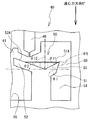
図19に示すように、特許文献1に開示の検査チップでは、検査対象の血液が開口101から内部に注入されて、遠心分離装置によって回転される。検査チップ内に注入された血液は、F0方向に作用する遠心力によって、毛管スロット102内を通って血液保持室103に移動し、さらに血液分離室104内に流れ込んで遠心分離される。一方、反応試剤室105から流出する反応試剤と、希釈剤室106から流出する希釈剤とが、反応試剤計量室107内に流れ込んで混合される。   As shown in FIG. 19, in the test chip disclosed in Patent Document 1, blood to be tested is injected into the inside from the opening 101 and rotated by a centrifugal separator. The blood injected into the test chip moves to the blood holding chamber 103 through the capillary slot 102 by the centrifugal force acting in the F0 direction, and further flows into the blood separation chamber 104 to be centrifuged. On the other hand, the reaction reagent flowing out from the reaction reagent chamber 105 and the diluent flowing out from the diluent chamber 106 flow into the reaction reagent metering chamber 107 and are mixed.

次に、検査チップを90°回転させることによって、F1方向に作用する遠心力が生じる。これにより、分離された血液の一部が血液分離室104から試料保持室108に移送され、且つ、混合された反応試剤が反応試剤計量室107から混合室109に移送される。さらに、検査チップを90°反転させることによって、再びF0方向に作用する遠心力が生じる。これにより、試料保持室108で保持されている血液が試料計量室110に移送され、且つ、混合室109で保持されている反応試剤がキュベット室111に移送される。最後に、検査チップの90°回転および90°反転を順に行うことによって、試料計量室110で保持されている血液と、キュベット室111で保持されている反応試剤とが混合される。その後、図示しない光源からキュベット室111に光を照射して、血液と反応試剤とが混合された液体の光学特性を計測することによって、血液の検査を行う。   Next, a centrifugal force acting in the F1 direction is generated by rotating the inspection chip by 90 °. Thereby, a part of the separated blood is transferred from the blood separation chamber 104 to the sample holding chamber 108, and the mixed reaction reagent is transferred from the reaction reagent measuring chamber 107 to the mixing chamber 109. Furthermore, by inverting the inspection chip by 90 °, a centrifugal force acting again in the F0 direction is generated. Thereby, the blood held in the sample holding chamber 108 is transferred to the sample measuring chamber 110, and the reaction reagent held in the mixing chamber 109 is transferred to the cuvette chamber 111. Finally, the blood held in the sample measuring chamber 110 and the reaction reagent held in the cuvette chamber 111 are mixed by performing 90 ° rotation and 90 ° inversion in order. Thereafter, the cuvette chamber 111 is irradiated with light from a light source (not shown) to measure the optical characteristics of the liquid in which the blood and the reaction reagent are mixed, thereby examining the blood.

特開昭60−238760号公報JP 60-238760 A

上記の検査チップでは、試料計量室110で正確な試料量を計量するために、過剰な試料が試料計量室110から試料溢流室112へ流れ出るようにしている。しかしながら、試料計量室110における試料溢流室112側の端部から連続して延びる壁面が、F0方向と直交する方向とほぼ平行である。言い換えると、試料計量室110の開口端から試料溢流室112に向けて延設された隔壁の上面(以下、試料案内面113と呼ぶ。)が、F0方向と直交する方向とほぼ平行である。   In the above inspection chip, in order to accurately measure the sample amount in the sample measuring chamber 110, an excessive sample flows out from the sample measuring chamber 110 to the sample overflow chamber 112. However, the wall surface continuously extending from the end portion on the sample overflow chamber 112 side in the sample measuring chamber 110 is substantially parallel to the direction orthogonal to the F0 direction. In other words, the upper surface of the partition wall (hereinafter referred to as the sample guide surface 113) extending from the open end of the sample measuring chamber 110 toward the sample overflow chamber 112 is substantially parallel to the direction orthogonal to the F0 direction. .

そのため、試料が試料計量室110に移送される場合に、試料計量室110から溢れ出た試料が、試料溢流室112へ流れ込まずに試料案内面113に留まりやすかった。この状態でF1方向に作用する遠心力が生じた場合、試料案内面113に留まってしまった試料が試料計量室110で保持されている試料と合流してしまう。そうすると、試料計量室110で計量された試料量が変わってしまい、正確な検査結果を得られないおそれがあった。   Therefore, when the sample is transferred to the sample measurement chamber 110, the sample overflowing from the sample measurement chamber 110 does not flow into the sample overflow chamber 112 and tends to stay on the sample guide surface 113. When centrifugal force acting in the F1 direction is generated in this state, the sample remaining on the sample guide surface 113 joins the sample held in the sample measuring chamber 110. If it does so, the sample amount measured in the sample measurement chamber 110 will change, and there existed a possibility that an exact test result could not be obtained.

本発明は、上述した課題を解決するためになされたものであり、液受部に不要な液体が混入することを抑制可能な検査対象受体を提供することを目的とする。   The present invention has been made to solve the above-described problems, and an object of the present invention is to provide an inspection object receiver that can suppress unnecessary liquid from being mixed into the liquid receiving portion.

本発明の一態様に係る検査対象受体は、回転軸から離間した位置で回転自在に保持され、且つ、前記回転軸を中心とした回転時に生じる遠心力によって検査対象の液体を検査する検査対象受体であって、前記検査対象受体の内部に前記液体を供給するための供給口と、前記遠心力が第一の方向に生じている場合に、前記供給口から供給された前記液体を前記第一の方向の下流側に案内する第一案内部と、前記第一案内部を案内された前記液体を受けて、所定量の前記液体を貯留可能な凹部である液受部と、前記液受部で前記所定量の前記液体が貯留され、且つ、前記遠心力が第一の方向に生じている場合に、前記液受部から流出する余剰分の前記液体を前記第一の方向の下流側に案内する第二案内部と、前記液受部よりも前記第一の方向の下流側に設けられ、前記第二案内部によって案内された前記余剰分の前記液体が貯留される余剰部とを備え、前記第二案内部は、前記液受部における前記余剰部側の端部から延びる壁面であり、且つ、前記液受部に貯留されている前記液体を前記余剰部とは異なる所定の箇所に流出させる際に付加される前記遠心力の方向である第二の方向と直交する垂直面に対して、前記第二の方向の下流側に傾斜するように延びることを特徴とする。   An inspection object receiver according to one aspect of the present invention is rotatably held at a position separated from a rotation axis, and inspects a liquid to be inspected by a centrifugal force generated at the time of rotation about the rotation axis. A supply port for supplying the liquid to the inside of the test target receiver, and the liquid supplied from the supply port when the centrifugal force is generated in the first direction. A first guide portion that guides downstream of the first direction; a liquid receiving portion that is a recess that receives the liquid guided through the first guide portion and can store a predetermined amount of the liquid; and When the predetermined amount of the liquid is stored in the liquid receiving portion and the centrifugal force is generated in the first direction, the excess liquid flowing out from the liquid receiving portion is transferred in the first direction. A second guide portion that guides downstream; and a lower portion in the first direction than the liquid receiving portion. A surplus portion that is provided on the side and stores the surplus liquid guided by the second guide portion, and the second guide portion extends from an end of the liquid receiving portion on the surplus portion side. It is a wall surface that extends and is orthogonal to a second direction that is the direction of the centrifugal force that is applied when the liquid stored in the liquid receiving portion flows out to a predetermined location different from the surplus portion. It extends so that it may incline in the downstream of said 2nd direction with respect to a perpendicular surface.

これによれば、検査対象受体に第一の方向の遠心力が付与された場合、供給口から供給された液体が第一案内部によって液受部へ案内されて、液受部で所定量の液体が貯留される。液受部から流出する余剰分の液体は、検査に使用されない不要な液体であるため、第二案内部によって余剰部へ案内されて、余剰部に収容される。第二案内部は、液受部における余剰部側の端部から、液受部に貯留されている液体を所定の箇所に流出させる際に付加される遠心力の方向である第二の方向と直交する垂直面に対して下流側に傾斜している。したがって、第二案内部に液体が残留している状態で第二の方向の遠心力が付与された場合でも、残留している液体は第二案内部を逆流しにくいため、不要な液体が液受部に混入することを抑制できる。   According to this, when the centrifugal force in the first direction is applied to the test object receiver, the liquid supplied from the supply port is guided to the liquid receiver by the first guide part, and the liquid receiver receives a predetermined amount. Of liquid is stored. Since the excess liquid flowing out from the liquid receiving part is an unnecessary liquid that is not used for the inspection, it is guided to the excessive part by the second guide part and stored in the excessive part. The second guide part has a second direction which is a direction of centrifugal force applied when the liquid stored in the liquid receiving part flows out from the end on the surplus part side in the liquid receiving part to a predetermined location. It inclines downstream with respect to the orthogonal vertical plane. Therefore, even when a centrifugal force in the second direction is applied in a state where the liquid remains in the second guide portion, the remaining liquid is unlikely to flow back through the second guide portion, so unnecessary liquid is liquid. It can suppress mixing in a receiving part.

上記態様に係る検査対象受体において、前記第二案内部と前記垂直面とのなす角のうち、前記垂直面を前記第二案内部と対向する側から前記第二案内部まで回転させた場合の角度θは、少なくとも5°以上であってもよい。この場合、角度θを少なくとも5°以上に設計するだけで、不要な液体が液受部に混入することを抑制できる。   In the inspection object receiver according to the above aspect, when the vertical surface is rotated from the side facing the second guide portion to the second guide portion among the angles formed by the second guide portion and the vertical surface. May be at least 5 ° or more. In this case, it is possible to suppress the unnecessary liquid from being mixed into the liquid receiving portion only by designing the angle θ to be at least 5 ° or more.

上記態様に係る検査対象受体において、前記角度θは、前記液体の粘度が1cP未満である場合、10°以上であってもよい。この場合、粘度が1cP未満の液体が使用される検査対象受体において、不要な液体が液受部に混入することを確実に抑制できる。   In the test object receptacle according to the above aspect, the angle θ may be 10 ° or more when the viscosity of the liquid is less than 1 cP. In this case, it is possible to reliably suppress the unnecessary liquid from being mixed into the liquid receiving part in the test object receiver in which the liquid having a viscosity of less than 1 cP is used.

上記態様に係る検査対象受体において、前記角度θは、前記液体の粘度が1cP以上である場合、15°以上であってもよい。この場合、粘度が1cP以上の液体が使用される検査対象受体において、不要な液体が液受部に混入することを確実に抑制できる。   In the test object receptacle according to the above aspect, the angle θ may be 15 ° or more when the viscosity of the liquid is 1 cP or more. In this case, it is possible to reliably suppress the unnecessary liquid from being mixed into the liquid receiving part in the test object receiver in which the liquid having a viscosity of 1 cP or more is used.

検査装置1の平面図である。1 is a plan view of an inspection apparatus 1. FIG. 検査装置1の左側面図である。2 is a left side view of the inspection apparatus 1. FIG. 図2に示す角度変更機構19を拡大した図である。It is the figure which expanded the angle change mechanism 19 shown in FIG. 検査チップ40の平面図である。4 is a plan view of an inspection chip 40. FIG. 遠心力方向の角度「0°」の状態を示す検査チップ40の部分拡大図である。It is the elements on larger scale of the test | inspection chip 40 which shows the state of the angle "0 degree" of a centrifugal force direction. 遠心力方向の角度「90°」の状態を示す検査チップ40の部分拡大図である。It is the elements on larger scale of the test | inspection chip 40 which shows the state of the angle "90 degree" of a centrifugal force direction. 血漿を検体とする検査チップ40を用いた実験例の実験データである。It is experiment data of the experiment example using the test | inspection chip 40 which uses plasma as a specimen. ラテックス試薬を検体とする検査チップ40を用いた実験例の実験データである。It is experiment data of the experiment example using the test | inspection chip 40 which uses a latex reagent as a test substance. 緩衝液を検体とする検査チップ40を用いた実験例の実験データである。It is experiment data of the experiment example using the test | inspection chip 40 which uses a buffer solution as a specimen. 検査装置1で実行される検査処理のフローチャートである。3 is a flowchart of an inspection process executed by the inspection apparatus 1. 試薬を充填した状態の検査チップ40の平面図である。It is a top view of the test | inspection chip 40 of the state with which the reagent was filled. 遠心力方向の角度「0°」の状態を示す検査チップ40の平面図である。It is a top view of the test | inspection chip 40 which shows the state of the angle "0 degree" of a centrifugal force direction. 遠心力方向の角度「30°」の状態を示す検査チップ40の平面図である。It is a top view of the test | inspection chip 40 which shows the state of the angle "30 degrees" of a centrifugal force direction. 遠心力方向の角度「60°」の状態を示す検査チップ40の平面図である。It is a top view of the test | inspection chip 40 which shows the state of the angle "60 degree" of a centrifugal force direction. 遠心力方向の角度「90°」の状態を示す検査チップ40の平面図である。It is a top view of the test | inspection chip 40 which shows the state of the angle "90 degree" of a centrifugal force direction. 遠心力方向の角度「0°」の状態を示す検査チップ40の他の平面図である。It is another top view of the test | inspection chip 40 which shows the state of the angle "0 degree" of a centrifugal force direction. 変形例に係る、遠心力方向の角度「0°」の状態を示す検査チップ80の平面図である。It is a top view of the test | inspection chip | tip 80 which shows the state of the angle "0 degree" of a centrifugal force direction based on a modification. 変形例に係る、遠心力方向の角度「90°」の状態を示す検査チップ80の平面図である。It is a top view of the test | inspection chip | tip 80 which shows the state of the angle "90 degree" of a centrifugal force direction based on a modification. 従来の検査チップの平面図である。It is a top view of the conventional test | inspection chip.

本発明を具体化した実施の形態について、図面を参照して説明する。参照する図面は、本発明が採用しうる技術的特徴を説明するために用いられるものであり、単なる説明例である。   Embodiments of the present invention will be described with reference to the drawings. The drawings to be referred to are used to explain technical features that can be adopted by the present invention, and are merely illustrative examples.

本実施形態では、検査対象である液体(以下、検体と呼ぶ。)および検体に混合される複数の液体(以下、試薬と呼ぶ。)を収容可能な検査チップ40を用いて、検査装置1で検査が行われる場合を例示する。検査装置1は、検査チップ40の回転角度を変化させることによって、検査チップ40に付与される遠心力の方向(以下、遠心力方向と呼ぶ。)を切り替え可能である。   In the present embodiment, the inspection apparatus 1 uses the inspection chip 40 that can store a liquid to be inspected (hereinafter referred to as a specimen) and a plurality of liquids (hereinafter referred to as reagents) mixed with the specimen. The case where a test | inspection is performed is illustrated. The inspection device 1 can switch the direction of the centrifugal force applied to the inspection chip 40 (hereinafter referred to as the centrifugal force direction) by changing the rotation angle of the inspection chip 40.

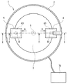
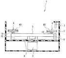
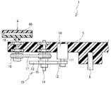
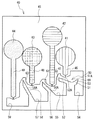
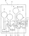
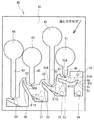
図1〜図3を参照して、検査装置1の概略構造について説明する。以下の説明では、図1の上方、下方、右方、左方を、それぞれ、検査装置1の右方、左方、前方、後方とする。図2の上方、下方、右方、左方を、それぞれ、検査装置1の上方、下方、前方、後方とする。なお、理解を容易にするために、図2では、外壁部2を図1に示すA−A線における矢視方向の断面図で示している。図3では、ターンテーブル3およびチップホルダ4を図1に示すY−Y線における矢視方向の断面図で示している。さらに、図2では角度変更機構19を簡略して箱状に示す一方、図3では角度変更機構19の詳細な構造を示している。   With reference to FIGS. 1-3, the schematic structure of the test | inspection apparatus 1 is demonstrated. In the following description, the upper, lower, right, and left sides in FIG. 1 are the right side, left side, front side, and rear side of the inspection apparatus 1, respectively. The upper, lower, right, and left sides in FIG. 2 are the upper, lower, front, and rear of the inspection apparatus 1, respectively. In addition, in order to make an understanding easy, in FIG. 2, the outer wall part 2 is shown with sectional drawing of the arrow direction in the AA line shown in FIG. In FIG. 3, the turntable 3 and the chip holder 4 are shown in a cross-sectional view in the direction of the arrow in the YY line shown in FIG. Further, FIG. 2 shows the angle changing mechanism 19 in a simplified box shape, while FIG. 3 shows the detailed structure of the angle changing mechanism 19.

検査装置1は、円筒形の筺体である外壁部2を備える。外壁部2の内部には、外壁部2よりも小径の円盤体であるターンテーブル3が回転自在に設けられている。ターンテーブル3の直径方向の両端部、すなわちターンテーブル3の円周近傍には、一対のチップホルダ4が各々設けられている。   The inspection apparatus 1 includes an outer wall portion 2 that is a cylindrical casing. Inside the outer wall 2, a turntable 3, which is a disk body having a smaller diameter than the outer wall 2, is rotatably provided. A pair of chip holders 4 are provided at both ends in the diameter direction of the turntable 3, that is, in the vicinity of the circumference of the turntable 3.

チップホルダ4は、一例として、底板と上板と側壁とで外形が形成された箱状体である。詳細には、チップホルダ4は、平面視長方形に形成された検査チップ40を内部に収納できるように、検査チップ40より一回り大きい平面視長方形に形成された箱状の部材である。チップホルダ4は、ターンテーブル3の回転中心(すなわち、後述の軸6)から離間した位置で、検査チップ40を保持する。検査者は、検査装置1の回転中心側から遠心方向に向けて(図1の例では、ターンテーブル3の回転中心から矢印Aに示す方向に向けて)、検査チップ40をチップホルダ4に装着可能である。   As an example, the chip holder 4 is a box-shaped body having an outer shape formed of a bottom plate, an upper plate, and a side wall. Specifically, the chip holder 4 is a box-like member formed in a rectangular shape in plan view that is slightly larger than the test chip 40 so that the test chip 40 formed in rectangular shape in plan view can be accommodated therein. The chip holder 4 holds the inspection chip 40 at a position separated from the rotation center of the turntable 3 (that is, a shaft 6 described later). The inspector attaches the inspection chip 40 to the chip holder 4 from the rotation center side of the inspection apparatus 1 toward the centrifugal direction (in the example of FIG. 1, from the rotation center of the turntable 3 toward the direction indicated by the arrow A). Is possible.

ターンテーブル3の中心部の下部には、モータ5が設けられている。モータ5は、モータ5から上方に延び、且つ、ターンテーブル3の平面中心に接続された軸6を備える。モータ5が軸6を回転させるのに伴って、ターンテーブル3も軸6を中心として回転する。   A motor 5 is provided at the lower part of the center of the turntable 3. The motor 5 includes a shaft 6 that extends upward from the motor 5 and is connected to the plane center of the turntable 3. As the motor 5 rotates the shaft 6, the turntable 3 also rotates about the shaft 6.

検査装置1は、チップホルダ4を水平方向に回転させることによって、チップホルダ4の回転角度を変更する角度変更機構19を備える。角度変更機構19は、検査装置1の遠心動作時にチップホルダ4の回転角度を変更することで、チップホルダ4に作用する遠心力方向を変更できる。   The inspection apparatus 1 includes an angle changing mechanism 19 that changes the rotation angle of the chip holder 4 by rotating the chip holder 4 in the horizontal direction. The angle changing mechanism 19 can change the direction of centrifugal force acting on the chip holder 4 by changing the rotation angle of the chip holder 4 during the centrifugal operation of the inspection apparatus 1.

角度変更機構19は、ステッピングモータ10、ギア12、ギア13、プーリ15、プーリ16、およびベルト17を備える。ギア12は、ステッピングモータ10の軸11に固定されている。ギア13は、ギア12と噛合する減速用ギアである。プーリ15は、ギア13の軸14に対して同軸に固定されている。プーリ16は、チップホルダ4を回転可能に軸支する軸18の下端部に対して同軸に固定されている。ベルト17は、プーリ15とプーリ16との間に掛け渡されている。   The angle changing mechanism 19 includes a stepping motor 10, a gear 12, a gear 13, a pulley 15, a pulley 16, and a belt 17. The gear 12 is fixed to the shaft 11 of the stepping motor 10. The gear 13 is a reduction gear that meshes with the gear 12. The pulley 15 is fixed coaxially with the shaft 14 of the gear 13. The pulley 16 is fixed coaxially to the lower end portion of the shaft 18 that rotatably supports the chip holder 4. The belt 17 is stretched between the pulley 15 and the pulley 16.

上記の構成により、ステッピングモータ10の軸11が所定角度回転すると、ギア12が回転して、ギア12と噛合しているギア13が回転する。ギア13の回転に伴って、軸14に固定されているプーリ15が回転する。プーリ15の回転はベルト17によりプーリ16に伝えられて、プーリ16が所定角度回転する。ひいては、軸18が所定角度回転して、チップホルダ4が所定角度回転する。   With the above configuration, when the shaft 11 of the stepping motor 10 rotates by a predetermined angle, the gear 12 rotates and the gear 13 meshing with the gear 12 rotates. As the gear 13 rotates, the pulley 15 fixed to the shaft 14 rotates. The rotation of the pulley 15 is transmitted to the pulley 16 by the belt 17, and the pulley 16 rotates by a predetermined angle. As a result, the axis | shaft 18 rotates a predetermined angle and the chip | tip holder 4 rotates a predetermined angle.

本実施形態では、ターンテーブル3がモータ5によって回転駆動されると、チップホルダ4に保持された検査チップ40も軸6を回転中心として回転する。軸6を回転中心とした検査チップ40の回転を、検査チップ40の「公転」と呼ぶ。一方、チップホルダ4がステッピングモータ10によって所定角度回転されると、チップホルダ4に保持された検査チップ40も軸18を回転中心として所定角度回転する。軸18を回転中心とした検査チップ40の回転を、検査チップ40の「自転」と呼ぶ。   In the present embodiment, when the turntable 3 is rotationally driven by the motor 5, the inspection chip 40 held by the chip holder 4 also rotates about the shaft 6 as a rotation center. The rotation of the inspection chip 40 around the axis 6 is called “revolution” of the inspection chip 40. On the other hand, when the chip holder 4 is rotated by a predetermined angle by the stepping motor 10, the inspection chip 40 held by the chip holder 4 also rotates by a predetermined angle around the shaft 18 as a rotation center. The rotation of the inspection chip 40 around the axis 18 is referred to as “rotation” of the inspection chip 40.

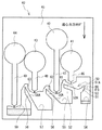
検査装置1は、外壁部2の外部に設けられた制御装置70に接続されている。制御装置70は、図示外のCPU、RAM、ROM等を内蔵して、検査装置1の各種動作(例えば、ターンテーブル3の回転や、チップホルダ4の回転など)を制御する。制御装置70には、検査者が検査装置1の各種動作を指示するための操作部(図示外)が設けられている。   The inspection device 1 is connected to a control device 70 provided outside the outer wall portion 2. The control device 70 incorporates a CPU, RAM, ROM, etc., not shown, and controls various operations of the inspection device 1 (for example, rotation of the turntable 3 and rotation of the chip holder 4). The control device 70 is provided with an operation unit (not shown) for an inspector to instruct various operations of the inspection device 1.

ターンテーブル3と外壁部2との間には、上下方向に対向する光源7および検出器8が設けられている。光源7は、検査チップ40内で生成された試薬と検体との混合物(つまり、反応生成物)に、検査チップ40の上方から光を照射する。検出器8は、反応生成物を透過した光を、検査チップ40の下方で検出する。制御装置70は、検出器8で検出された受光量に基づいて、各種測定を実行できる。なお、光源7および検出器8を検査チップ40に対して同一方向に設けることで、反応生成物で反射する光を検出して各種測定を行ってもよい。   Between the turntable 3 and the outer wall 2, a light source 7 and a detector 8 that are vertically opposed are provided. The light source 7 irradiates the mixture (that is, reaction product) of the reagent and specimen generated in the test chip 40 with light from above the test chip 40. The detector 8 detects the light transmitted through the reaction product below the inspection chip 40. The control device 70 can perform various measurements based on the amount of received light detected by the detector 8. In addition, by providing the light source 7 and the detector 8 in the same direction with respect to the test chip 40, various measurements may be performed by detecting light reflected by the reaction product.

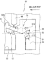
図4および図5を参照して、検査チップ40の概略構造について説明する。以下では、図4および図5の上方、下方、右方、左方を、それぞれ、検査チップ40の前方、後方、右方、左方として説明する。また、図4および図5の紙面手前側および紙面奥側を、それぞれ、検査チップ40の上方および下方として説明する。   A schematic structure of the inspection chip 40 will be described with reference to FIGS. 4 and 5. Hereinafter, the upper, lower, right, and left sides in FIGS. 4 and 5 will be described as the front, rear, right, and left sides of the test chip 40, respectively. Also, the front side and the back side of FIG. 4 and FIG. 5 will be described as being above and below the inspection chip 40, respectively.

本実施形態では、検査装置1で検査チップ40を使用する場合、検査チップ40の上下方向が検査装置1の上下方向と一致するように、検査者が検査チップ40を水平にチップホルダ4に装着する。このとき、検査者は、検査チップ40の前後方向が遠心力方向(つまり、矢印Aに示す方向)と一致するように、且つ、検査チップ40の前側および後側が遠心力方向の上流側および下流側とそれぞれ一致するように、検査チップ40をチップホルダ4に装着する(図1参照)。   In this embodiment, when the inspection chip 40 is used in the inspection apparatus 1, the inspector attaches the inspection chip 40 to the chip holder 4 so that the vertical direction of the inspection chip 40 coincides with the vertical direction of the inspection apparatus 1. To do. At this time, the inspector makes sure that the front-rear direction of the inspection chip 40 coincides with the centrifugal force direction (that is, the direction indicated by the arrow A), and the front side and the rear side of the inspection chip 40 are upstream and downstream in the centrifugal force direction. The inspection chip 40 is mounted on the chip holder 4 so as to match each side (see FIG. 1).

検査チップ40は、前後方向を長手方向とする、平面視長方形状の薄手の箱状体である。検査チップ40の材質は特に制限されず、ポリエチレンテレフタレート(PET)、ポリブチレンテレフタレート(PBT)、ポリメチルメタクリレート(PMMA)、ポリカーボネート(PC)、ポリスチレン(PS)、ポリプロピレン(PP)、ポリエチレン(PE)、ポリエチレンナフタレート(PEN)、ポリアリレート樹脂(PAR)、アクリロニトリル・ブタジエン・スチレン樹脂(ABS)、塩化ビニル樹脂(PVC)、ポリメチルペンテン樹脂(PMP)、ポリブタジエン樹脂(PBD)、生分解性ポリマー(BP)、シクロオレフィンポリマー(COP)、ポリジメチルシロキサン(PDMS)などの有機材料を用いることができる。また、シリコン、ガラス、石英等の無機材料を用いても良い。   The inspection chip 40 is a thin box-shaped body having a rectangular shape in plan view, the longitudinal direction being the front-rear direction. The material of the inspection chip 40 is not particularly limited, and polyethylene terephthalate (PET), polybutylene terephthalate (PBT), polymethyl methacrylate (PMMA), polycarbonate (PC), polystyrene (PS), polypropylene (PP), polyethylene (PE) , Polyethylene naphthalate (PEN), polyarylate resin (PAR), acrylonitrile butadiene styrene resin (ABS), vinyl chloride resin (PVC), polymethylpentene resin (PMP), polybutadiene resin (PBD), biodegradable polymer Organic materials such as (BP), cycloolefin polymer (COP), and polydimethylsiloxane (PDMS) can be used. In addition, an inorganic material such as silicon, glass, or quartz may be used.

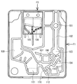
検査チップ40は、所定の厚みを有する合成樹脂の板材45によって外形が構成されている。検体投入口41、第一試薬投入口42、第二試薬投入口43、および第三試薬投入口44が、板材45に平面視円形の窪みとして形成されている。検体投入口41、第一試薬投入口42、第二試薬投入口43、第三試薬投入口44は、間隔を空けて右側から左側に並んで形成されている。   The outer shape of the inspection chip 40 is configured by a synthetic resin plate 45 having a predetermined thickness. A sample inlet 41, a first reagent inlet 42, a second reagent inlet 43, and a third reagent inlet 44 are formed in the plate member 45 as a circular recess in plan view. The sample inlet 41, the first reagent inlet 42, the second reagent inlet 43, and the third reagent inlet 44 are formed side by side from the right side to the left side with a space therebetween.

図示しないが、検査チップ40の上面は、透明の合成樹脂製の蓋(図示外)で覆われている。この蓋には、検体投入口41、第一試薬投入口42、第二試薬投入口43、および第三試薬投入口44と対応する位置のみに、それぞれ開口が形成されている。つまり、検査チップ40の上面のうちで、検体投入口41、第一試薬投入口42、第二試薬投入口43、および第三試薬投入口44のみが上方に開口している。   Although not shown, the upper surface of the inspection chip 40 is covered with a transparent synthetic resin lid (not shown). In the lid, openings are formed only at positions corresponding to the sample inlet 41, the first reagent inlet 42, the second reagent inlet 43, and the third reagent inlet 44, respectively. That is, only the sample inlet 41, the first reagent inlet 42, the second reagent inlet 43, and the third reagent inlet 44 are opened upward on the upper surface of the test chip 40.

検体投入口41は、検査チップ40内に検体を供給するために、検査者が検体を投入する部位である。第一試薬投入口42、第二試薬投入口43、および第三試薬投入口44は、検査チップ40内に第一試薬、第二試薬、および第三試薬をそれぞれ供給するために、検査者がこれらの試薬を投入する部位である。従って、検査者は検査チップ40内に一つの検体に三つの試薬を投入して、これらの検体および試薬を混合させることができる。   The sample insertion port 41 is a part into which a tester inputs a sample in order to supply the sample into the test chip 40. The first reagent inlet 42, the second reagent inlet 43, and the third reagent inlet 44 are used by the inspector to supply the first reagent, the second reagent, and the third reagent into the inspection chip 40, respectively. This is the site where these reagents are charged. Therefore, the examiner can put three reagents into one sample in the test chip 40 and mix these samples and reagents.

また、検体供給路46、第一試薬供給路47、第二試薬供給路48、および第三試薬供給路49が、板材45に溝状に形成されている。検体供給路46は、検体投入口41から後方に延びる、検体の流路である。第一試薬供給路47は、第一試薬投入口42から後方に延びる、第一試薬の流路である。第二試薬供給路48は、第二試薬投入口43から後方に延びる、第二試薬の流路である。第三試薬供給路49は、第三試薬投入口44から後方に延びる、第三試薬の流路である。   A sample supply path 46, a first reagent supply path 47, a second reagent supply path 48, and a third reagent supply path 49 are formed in the plate material 45 in a groove shape. The sample supply path 46 is a sample flow path extending rearward from the sample input port 41. The first reagent supply path 47 is a first reagent flow path extending rearward from the first reagent inlet 42. The second reagent supply path 48 is a second reagent flow path extending backward from the second reagent inlet 43. The third reagent supply path 49 is a third reagent flow path extending backward from the third reagent inlet 44.

検体供給路46、第一試薬供給路47、第二試薬供給路48、および第三試薬供給路49は、それぞれ平行に延設されている。つまり、これらの供給路の延設方向は、検査チップ40の前後方向とも平行である。検体供給路46、第一試薬供給路47、第二試薬供給路48、および第三試薬供給路49の後端部には、幅が狭くなった出口が各々設けられている。   The sample supply path 46, the first reagent supply path 47, the second reagent supply path 48, and the third reagent supply path 49 are each extended in parallel. That is, the extending direction of these supply paths is parallel to the front-rear direction of the inspection chip 40. At the rear ends of the sample supply path 46, the first reagent supply path 47, the second reagent supply path 48, and the third reagent supply path 49, an outlet having a narrow width is provided.

検体供給路46の後方側(図4における下方側)には、検体供給路46から供給される検体を所定量計量するための計量部50が形成されている。計量部50は、第一壁部51と第二壁部52との間に形成された、平面視で後方に凹む部位である。第二壁部52は、検体供給路46の出口と前後方向に対向する壁面52Aを有する壁部である。第一壁部51は、壁面52Aから右側に連続して延設された壁面51Aを有する壁部である。詳細には、計量部50は、壁面51Aと壁面52Aとで形成され、平面視で後方に向かってV字型に凹んでいる。   On the rear side (the lower side in FIG. 4) of the sample supply path 46, a measuring unit 50 for measuring a predetermined amount of the sample supplied from the sample supply path 46 is formed. The measuring part 50 is a part that is formed between the first wall part 51 and the second wall part 52 and is recessed rearward in plan view. The second wall portion 52 is a wall portion having a wall surface 52A facing the outlet of the sample supply path 46 in the front-rear direction. The first wall portion 51 is a wall portion having a wall surface 51A continuously extending to the right side from the wall surface 52A. Specifically, the measuring unit 50 is formed of a wall surface 51A and a wall surface 52A, and is recessed in a V shape toward the rear in plan view.

第二壁部52の外縁に沿って、第一流路61が板材45に溝状に形成されている。第一流路61は、計量部50で計量された検体を、後述の第一混合槽55へ案内する流路である。一方、第一壁部51の外縁に沿って、流出路60が板材45に溝状に形成されている。流出路60は、計量部50から流れ出た検体(すなわち、余った検体)を、余剰槽54へ案内する流路である。余剰槽54は、第一壁部51の後方に設けられた、平面視で後方に凹む部位であって、計量部50から流れ出た検体が貯留される。   A first flow path 61 is formed in the plate material 45 in a groove shape along the outer edge of the second wall portion 52. The first flow path 61 is a flow path for guiding the sample measured by the measuring unit 50 to the first mixing tank 55 described later. On the other hand, the outflow path 60 is formed in the plate material 45 in a groove shape along the outer edge of the first wall portion 51. The outflow path 60 is a flow path for guiding the sample flowing out from the measuring unit 50 (that is, the surplus sample) to the surplus tank 54. The surplus tank 54 is a portion that is provided behind the first wall portion 51 and that is recessed rearward in plan view, and stores the specimen that has flowed out of the measuring unit 50.

壁面51Aの延設方向と検査チップ40の左右方向とのなす角度が、第一角度θ1である。より詳細には、第一角度θ1は、平面視で壁面51Aの延設方向に延びる線と検査チップ40の左右方向に延びる線との交点を回転中心として、壁面51Aを左右方向と平行になるまで時計回り方向に回転させた場合の角度である。本実施形態では、第一角度θ1が少なくとも鋭角(一例として、20°)となるように、第一壁部51が右前方に延設されている。   The angle formed between the extending direction of the wall surface 51A and the horizontal direction of the inspection chip 40 is the first angle θ1. More specifically, the first angle θ1 is parallel to the left-right direction with the intersection point of the line extending in the extending direction of the wall surface 51A and the line extending in the left-right direction of the test chip 40 as the rotation center in plan view. This is the angle when rotated clockwise until. In the present embodiment, the first wall portion 51 extends to the right front so that the first angle θ1 is at least an acute angle (for example, 20 °).

一方、壁面52Aの延設方向と検査チップ40の左右方向とのなす角度は、第二角度θ2である。より詳細には、第二角度θ2は、平面視で壁面52Aの延設方向に延びる線と検査チップ40の左右方向に延びる線との交点を回転中心として、壁面52Aを左右方向と平行になるまで反時計回り方向に回転させた場合の角度である。本実施形態では、第二角度θ2が少なくとも鋭角(一例として、15°)となるように、第二壁部52が左前方に延設されている。なお、壁面51A、52Aの延設方向の角度および長さは、上記条件を満たす範囲で、計量部50で計り取る検体の量に応じて決定されればよい。また、計量部50は、例えばU字型や矩形状など、平面視でV字型とは異なる形状で凹むように形成されてもよい。   On the other hand, the angle formed by the extending direction of the wall surface 52A and the horizontal direction of the inspection chip 40 is the second angle θ2. More specifically, the second angle θ <b> 2 is parallel to the left-right direction with the wall 52 </ b> A being parallel to the left-right direction with the intersection point between the line extending in the extending direction of the wall surface 52 </ b> A and the line extending in the left-right direction of the inspection chip 40 in plan view. It is an angle when rotating counterclockwise until. In the present embodiment, the second wall portion 52 is extended to the left front so that the second angle θ2 is at least an acute angle (for example, 15 °). The angles and lengths of the wall surfaces 51A and 52A in the extending direction may be determined according to the amount of the sample measured by the measuring unit 50 within a range that satisfies the above conditions. Moreover, the measurement part 50 may be formed so as to be recessed in a shape different from the V shape in plan view, such as a U shape or a rectangular shape.

第一壁部51において壁面51Aの右端部(つまり、余剰槽54側の端部)から後方に連続して延びる壁面は、案内面53である。案内面53は、流出路60に流れ出た検体を余剰槽54に向けて案内する。案内面53は、計量部50で計量された検体を第一流路61へ流出させる遠心力方向と直交する垂直面に対して、遠心力方向の下流側に傾斜するように延びているが、詳細は後述する。   A wall surface that continuously extends rearward from the right end portion (that is, the end portion on the surplus tank 54 side) of the wall surface 51 </ b> A in the first wall portion 51 is a guide surface 53. The guide surface 53 guides the specimen flowing out to the outflow path 60 toward the surplus tank 54. The guide surface 53 extends so as to incline toward the downstream side in the centrifugal force direction with respect to a vertical surface orthogonal to the centrifugal force direction that causes the sample measured by the measuring unit 50 to flow out to the first flow path 61. Will be described later.

第一試薬供給路47の後方側(図4における下方側)には、第一混合槽55が形成されている。第一混合槽55は、第三壁部56と第三壁部56から右方に延びる壁部との間に形成された、平面視で後方に凹む部位である。第三壁部56は、第一試薬供給路47の出口と前後方向に対向する壁面56Aを有する壁部である。第一混合槽55では、第一流路61を経由して流れ出た検体と、第一試薬供給路47から供給された第一試薬とが混合されて、第一混合液が生成される。第三壁部56の外縁に沿って、第二流路62が板材45に溝状に形成されている。第二流路62は、第一混合槽55で生成された第一混合液を、後述の第二混合槽57へ案内する流路である。   A first mixing tank 55 is formed on the rear side (the lower side in FIG. 4) of the first reagent supply path 47. The first mixing tank 55 is a portion that is formed between the third wall portion 56 and the wall portion extending rightward from the third wall portion 56 and is recessed rearward in plan view. The third wall portion 56 is a wall portion having a wall surface 56A facing the outlet of the first reagent supply path 47 in the front-rear direction. In the first mixing tank 55, the sample flowing out through the first flow path 61 and the first reagent supplied from the first reagent supply path 47 are mixed to generate a first mixed liquid. A second flow path 62 is formed in the plate material 45 in a groove shape along the outer edge of the third wall portion 56. The second flow path 62 is a flow path for guiding the first mixed liquid generated in the first mixing tank 55 to the second mixing tank 57 described later.

壁面56Aの延設方向と検査チップ40の左右方向とのなす角度は、第三角度θ3である。より詳細には、第三角度θ3は、平面視で壁面56Aの延設方向に延びる線と検査チップ40の左右方向に延びる線との交点を回転中心として、壁面56Aを左右方向と平行になるまで反時計回り方向に回転させた場合の角度である。本実施形態では、第三角度θ3が少なくとも第二角度θ2よりも大きい鋭角(一例として、45°)となるように、第三壁部56が左前方に延設されている。   The angle formed between the extending direction of the wall surface 56A and the horizontal direction of the inspection chip 40 is the third angle θ3. More specifically, the third angle θ3 is parallel to the left-right direction with the intersection point between the line extending in the extending direction of the wall surface 56A and the line extending in the left-right direction of the inspection chip 40 as viewed in plan. It is an angle when rotating counterclockwise until. In the present embodiment, the third wall portion 56 extends leftward and forward so that the third angle θ3 is an acute angle (for example, 45 °) that is at least larger than the second angle θ2.

第二試薬供給路48の後方側(図4における下方側)には、第二混合槽57が形成されている。第二混合槽57は、第四壁部58と第四壁部58から右方に延びる壁部との間に形成された、平面視で後方に凹む部位である。第四壁部58は、第二試薬供給路48の出口と前後方向に対向する壁面58Aを有する壁部である。第二混合槽57では、第二流路62を経由して流れ出た第一混合液と、第二試薬供給路48から供給された第二試薬とが混合されて、第二混合液が生成される。第四壁部58の外縁に沿って、第三流路63が板材45に溝状に形成されている。第三流路63は、第二混合槽57で生成された第二混合液を、後述の第三混合槽59へ案内する流路である。   A second mixing tank 57 is formed on the rear side (the lower side in FIG. 4) of the second reagent supply path 48. The second mixing tank 57 is a portion that is formed between the fourth wall portion 58 and the wall portion extending rightward from the fourth wall portion 58 and that is recessed rearward in plan view. The fourth wall portion 58 is a wall portion having a wall surface 58A facing the outlet of the second reagent supply path 48 in the front-rear direction. In the second mixing tank 57, the first mixed liquid flowing out via the second flow path 62 and the second reagent supplied from the second reagent supply path 48 are mixed to generate a second mixed liquid. The A third flow path 63 is formed in the plate material 45 in a groove shape along the outer edge of the fourth wall portion 58. The third flow path 63 is a flow path for guiding the second mixed liquid generated in the second mixing tank 57 to the third mixing tank 59 described later.

壁面58Aの延設方向と検査チップ40の左右方向とのなす角度は、第四角度θ4である。より詳細には、第四角度θ4は、平面視で壁面58Aの延設方向に延びる線と検査チップ40の左右方向に延びる線との交点を回転中心として、壁面58Aを左右方向と平行になるまで反時計回り方向に回転させた場合の角度である。本実施形態では、第四角度θ4が少なくとも第三角度θ3よりも大きい鋭角(一例として、75°)となるように、第四壁部58が左前方に延設されている。   The angle formed between the extending direction of the wall surface 58A and the horizontal direction of the inspection chip 40 is the fourth angle θ4. More specifically, the fourth angle θ4 is parallel to the horizontal direction of the wall surface 58A with the intersection point between the line extending in the extending direction of the wall surface 58A and the line extending in the horizontal direction of the inspection chip 40 as viewed in plan. It is an angle when rotating counterclockwise until. In the present embodiment, the fourth wall portion 58 extends to the left front so that the fourth angle θ4 is an acute angle (as an example, 75 °) that is at least larger than the third angle θ3.

第三試薬供給路49の後方側(図4における下方側)には、第三混合槽59が形成されている。第三混合槽59は、第三試薬供給路49の後方側に設けられた、平面視で後方に凹む部位である。第三混合槽59では、第三流路63を経由して流れ出た第二混合液と、第三試薬供給路49から供給された第三試薬とが混合されて、第三混合液が生成される。なお、本実施形態では、計量部50、余剰槽54、第一混合槽55、第二混合槽57、および第三混合槽59は、いずれも板材45に対する窪みとして形成されている。   A third mixing tank 59 is formed on the rear side (lower side in FIG. 4) of the third reagent supply path 49. The third mixing tank 59 is a portion that is provided on the rear side of the third reagent supply path 49 and that is recessed rearward in plan view. In the third mixing tank 59, the second mixed liquid flowing out through the third flow path 63 and the third reagent supplied from the third reagent supply path 49 are mixed to generate a third mixed liquid. The In the present embodiment, the measuring unit 50, the surplus tank 54, the first mixing tank 55, the second mixing tank 57, and the third mixing tank 59 are all formed as depressions with respect to the plate material 45.

上記のように検査チップ40では、複数の混合槽(すなわち、第一混合槽55、第二混合槽57、および第三混合槽59)が左右方向に並設されている。さらに、各混合槽の壁部(すなわち、第二壁部52、第三壁部56、および第四壁部58)の延設角度は、互いに異なった角度に形成されている。ただし、各混合槽の壁部の延設角度(すなわち、第二角度θ2、第三角度θ3、および第四角度θ4)は、平面視で各壁部の壁面(すなわち、壁面52A、壁面56A、および壁面58A)が左前方に延びるように、検査チップ40の左右方向に対して鋭角である。本実施形態では、第二角度θ2、第三角度θ3、第四角度θ4は、それぞれ15°、45°、75°に設定されている。   As described above, in the inspection chip 40, a plurality of mixing tanks (that is, the first mixing tank 55, the second mixing tank 57, and the third mixing tank 59) are arranged in parallel in the left-right direction. Furthermore, the extending angles of the wall portions (that is, the second wall portion 52, the third wall portion 56, and the fourth wall portion 58) of each mixing tank are formed at different angles. However, the extension angles (that is, the second angle θ2, the third angle θ3, and the fourth angle θ4) of the walls of each mixing tank are the wall surfaces (that is, the wall surfaces 52A, 56A, The wall surface 58A) has an acute angle with respect to the left-right direction of the test chip 40 so that the wall surface 58A extends to the left front. In the present embodiment, the second angle θ2, the third angle θ3, and the fourth angle θ4 are set to 15 °, 45 °, and 75 °, respectively.

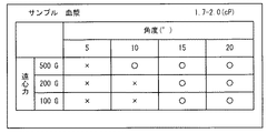
図5〜図9を参照して、計量部50近傍の詳細構造について説明する。図7〜図9において、「角度」は、後述の第五角度θ5の大きさを示す。「○」は、案内面53への液乗りがないことを示す。「×」は、案内面53への液乗りがあることを示す。なお、案内面53への液乗りとは、案内面53に置かれた検体が、案内面53から流れ落ちずに残留した状態をいう。   With reference to FIGS. 5-9, the detailed structure of the measurement part 50 vicinity is demonstrated. 7 to 9, “Angle” indicates the size of a fifth angle θ5 described later. “◯” indicates that there is no liquid ride on the guide surface 53. “X” indicates that there is liquid riding on the guide surface 53. The liquid riding on the guide surface 53 means a state in which the specimen placed on the guide surface 53 remains without flowing down from the guide surface 53.

図5および図6に示すように、検査チップ40の前後方向と壁面51Aの延設方向とのなす角のうち、計量部50側の角度θ11は鋭角である。検査チップ40の前後方向と壁面52Aの延設方向とのなす角のうち、計量部50側の角度θ12は鋭角である。図1に示す例のように、検査チップ40の前側から後方に向けて作用する遠心力を発生した場合、検査チップ40の前後方向は遠心力方向と一致する。このとき、遠心力の作用によって、検体は検体供給路46を経由したのち、計量部50で後方に移動しないように受け止められる。さらに、計量部50では、遠心力の作用によって所定量まで検体が貯留される。   As shown in FIGS. 5 and 6, among the angles formed by the front-rear direction of the test chip 40 and the extending direction of the wall surface 51 </ b> A, the angle θ <b> 11 on the measuring unit 50 side is an acute angle. Of the angles formed by the front-rear direction of the inspection chip 40 and the extending direction of the wall surface 52A, the angle θ12 on the weighing unit 50 side is an acute angle. As in the example illustrated in FIG. 1, when a centrifugal force acting from the front side to the rear side of the test chip 40 is generated, the front-rear direction of the test chip 40 matches the centrifugal force direction. At this time, due to the action of the centrifugal force, the specimen is received by the measuring section 50 so as not to move backward after passing through the specimen supply path 46. Further, in the measuring unit 50, the specimen is stored up to a predetermined amount by the action of centrifugal force.

壁面51Aおよび壁面52Aが接続される前後方向位置を基準として、壁面51Aの前後方向長さ(高さ)は壁面52Aの前後方向長さ(高さ)よりも短い(低い)。壁面51Aの高さまでの容積を超える量の検体が計量部50に流れ込むと、余剰分の検体が壁面51Aを乗り越えて(つまり、計量部50から流出路60に溢れて)、余剰槽54に流れ込む。余剰槽54では、遠心力の作用によって余剰分の検体が貯留される。従って、計量部50では、所定量の検体が計量される。なお、壁面51A、52Aの高さや角度は、計量部50で計量される所定量(つまり、計量部50の容積)に応じて予め決定されればよい。   The front-rear direction length (height) of the wall surface 51A is shorter (lower) than the front-rear direction length (height) of the wall surface 52A with reference to the front-rear direction position where the wall surface 51A and the wall surface 52A are connected. When a sample exceeding the volume up to the height of the wall surface 51A flows into the measuring unit 50, the surplus sample gets over the wall surface 51A (that is, overflows from the measuring unit 50 to the outflow path 60) and flows into the surplus tank 54. . In the surplus tank 54, surplus samples are stored by the action of centrifugal force. Therefore, the measuring unit 50 measures a predetermined amount of sample. The heights and angles of the wall surfaces 51A and 52A may be determined in advance according to a predetermined amount measured by the measuring unit 50 (that is, the volume of the measuring unit 50).

案内面53の延設方向と、検査チップ40に付与される遠心力の方向と直交する垂直面とのなす角度は、第五角度θ5である。より詳細には、第五角度θ5は、平面視で案内面53の延設方向に延びる線と遠心力方向と直交する垂直線との交点を回転中心として、案内面53をこの垂直線と平行になるまで反時計回り方向に回転させた場合の角度である。先述したように、案内面53は遠心力方向と直交する垂直面に対して遠心力方向の下流側に傾斜するように延びているため、第五角度θ5は少なくとも0°よりも大である。   The angle formed between the extending direction of the guide surface 53 and the vertical plane orthogonal to the direction of the centrifugal force applied to the test chip 40 is the fifth angle θ5. More specifically, the fifth angle θ5 has the guide surface 53 parallel to the vertical line with the intersection point between a line extending in the extending direction of the guide surface 53 and a vertical line orthogonal to the centrifugal force direction as viewed in plan view. This is the angle when rotated counterclockwise until As described above, since the guide surface 53 extends so as to incline to the downstream side in the centrifugal force direction with respect to the vertical plane orthogonal to the centrifugal force direction, the fifth angle θ5 is at least greater than 0 °.

第五角度θ5の大きさは、検査チップ40に付与される遠心力の方向に応じて変化する。具体的には、図5に示すように、検査チップ40の前側から後方に向けて遠心力が作用している場合は、第五角度θ5は案内面53の延設方向と検査チップ40の左右方向とのなす角度となる。一方、図6に示すように、検査チップ40の右側から左方に向けて遠心力が作用している場合は、第五角度θ5は案内面53の延設方向と検査チップ40の前後方向とのなす角度となる。   The magnitude of the fifth angle θ5 changes according to the direction of the centrifugal force applied to the inspection chip 40. Specifically, as shown in FIG. 5, when a centrifugal force is applied from the front side to the rear side of the test chip 40, the fifth angle θ <b> 5 is the extension direction of the guide surface 53 and the left and right sides of the test chip 40. It is the angle made with the direction. On the other hand, as shown in FIG. 6, when a centrifugal force is acting from the right side to the left side of the test chip 40, the fifth angle θ5 is the extension direction of the guide surface 53 and the front-rear direction of the test chip 40. The angle formed by

先述したように、計量部50から流出路60に流れ出た検体は、案内面53によって余剰槽54に向けて案内される。このとき検体が案内面53に液乗りしないように、案内面53の延設角度(つまり、第五角度θ5)は各種要素を考慮して決定される。本実施形態では、第五角度θ5を決定するための要素として、検体の粘度および遠心力を用いた場合を例示する。   As described above, the specimen that has flowed from the measuring unit 50 to the outflow path 60 is guided toward the surplus tank 54 by the guide surface 53. At this time, the extension angle of the guide surface 53 (that is, the fifth angle θ5) is determined in consideration of various factors so that the sample does not ride on the guide surface 53. In this embodiment, the case where the viscosity and centrifugal force of the specimen are used as elements for determining the fifth angle θ5 is illustrated.

本願の発明者は、検査装置1で検査チップ40の遠心処理を行うことで、案内面53への液乗りを評価する実験を行った。この実験では、例えば図1に示す状態で検査チップ40の遠心処理を行なって、検査チップ40の前側から後方に向けて作用する遠心力を発生させた。この遠心力によって、検体投入口41から投入された検体は、検体供給路46経由で計量部50に移動する。計量部50で計量される検体量を超えた余剰分の検体は、計量部50から流出路60に溢れ出て、案内面53を滑り落ちるように余剰槽54に移動する。かかる実験において、第五角度θ5、検体の粘度、および遠心力を適宜変更することで、案内面53に検体が残留するか否かを検証した。   The inventor of the present application conducted an experiment for evaluating the liquid riding on the guide surface 53 by performing the centrifugal treatment of the inspection chip 40 with the inspection device 1. In this experiment, for example, the test chip 40 is centrifuged in the state shown in FIG. 1 to generate a centrifugal force acting from the front side of the test chip 40 toward the rear. Due to this centrifugal force, the sample input from the sample input port 41 moves to the measuring unit 50 via the sample supply path 46. The surplus sample exceeding the sample amount weighed by the measuring unit 50 overflows from the measuring unit 50 to the outflow path 60 and moves to the surplus tank 54 so as to slide down the guide surface 53. In this experiment, it was verified whether or not the specimen remained on the guide surface 53 by appropriately changing the fifth angle θ5, the viscosity of the specimen, and the centrifugal force.

図7に示す実験例では、それぞれ異なる大きさの第五角度θ5(5°、10°、15°、20°)を有し、且つ、検体として「血漿」がそれぞれ収容された各検査チップ40について、上記実験を行った。このとき、それぞれ異なる大きさの遠心力(500G、200G、100G)を、各検査チップ40に付与した。そして、案内面53に対する「血漿」の液乗りを、遠心力および第五角度θ5の組み合わせごとに評価した。なお、「血漿」の粘度は、1.7〜2.0cPである。   In the experimental example shown in FIG. 7, each test chip 40 having a fifth angle θ5 (5 °, 10 °, 15 °, 20 °) having a different size and each containing “plasma” as a specimen. The above experiment was conducted. At this time, centrifugal forces (500G, 200G, and 100G) having different sizes were applied to the test chips 40, respectively. Then, the liquid riding of “plasma” on the guide surface 53 was evaluated for each combination of the centrifugal force and the fifth angle θ5. The viscosity of “plasma” is 1.7 to 2.0 cP.

上記実験によれば、第五角度θ5が「5°」の検査チップ40では、遠心力が「100G」、「200G」、および「500G」のいずれであっても、「血漿」の液乗りが生じた。第五角度θ5が「10°」の検査チップ40では、遠心力が「100G」および「200G」である場合、「血漿」の液乗りが生じた一方、遠心力が「500G」である場合、「血漿」の液乗りが生じなかった。第五角度θ5が「15°」および「20°」の各検査チップ40では、遠心力が「100G」、「200G」、および「500G」のいずれであっても、「血漿」の液乗りが生じなかった。   According to the above-described experiment, in the test chip 40 having the fifth angle θ5 of “5 °”, even if the centrifugal force is any of “100G”, “200G”, and “500G”, the “plasma” liquid riding is performed. occured. In the test chip 40 having the fifth angle θ5 of “10 °”, when the centrifugal force is “100 G” and “200 G”, the liquid riding of “plasma” occurs, while the centrifugal force is “500 G”. There was no “plasma” riding. In each of the test chips 40 having the fifth angle θ5 of “15 °” and “20 °”, even if the centrifugal force is “100G”, “200G”, and “500G”, the “plasma” liquid riding is performed. Did not occur.

図8に示す実験例では、それぞれ異なる大きさの第五角度θ5(5°、10°、15°、20°)を有し、且つ、検体として「ラテックス試薬」がそれぞれ収容された各検査チップ40について、上記実験を行った。このとき、それぞれ異なる大きさの遠心力(500G、200G、100G)を、各検査チップ40に付与した。そして、案内面53に対する「ラテックス試薬」の液乗りを、遠心力および第五角度θ5の組み合わせごとに評価した。なお、「ラテックス試薬」の粘度は、0.89cPである。   In the experimental example shown in FIG. 8, each test chip has a fifth angle θ5 (5 °, 10 °, 15 °, 20 °) having a different size and contains a “latex reagent” as a specimen. The above experiment was conducted for 40. At this time, centrifugal forces (500G, 200G, and 100G) having different sizes were applied to the test chips 40, respectively. And the liquid riding of the "latex reagent" with respect to the guide surface 53 was evaluated for every combination of centrifugal force and 5th angle (theta) 5. The viscosity of the “latex reagent” is 0.89 cP.

上記実験によれば、第五角度θ5が「5°」の検査チップ40では、遠心力が「100G」、「200G」、および「500G」のいずれであっても、「血漿」の液乗りが生じた。第五角度θ5が「10°」、「15°」、および「20°」の各検査チップ40では、遠心力が「100G」、「200G」、および「500G」のいずれであっても、「ラテックス試薬」の液乗りが生じなかった。   According to the above-described experiment, in the test chip 40 having the fifth angle θ5 of “5 °”, even if the centrifugal force is any of “100G”, “200G”, and “500G”, the “plasma” liquid ride is occured. In each inspection chip 40 having the fifth angle θ5 of “10 °”, “15 °”, and “20 °”, the centrifugal force is “100G”, “200G”, and “500G”. The liquid loading of “latex reagent” did not occur.

図9に示す実験例では、それぞれ異なる大きさの第五角度θ5(5°、10°、15°、20°)を有し、且つ、検体として「緩衝液」がそれぞれ収容された各検査チップ40について、上記実験を行った。それぞれ異なる大きさの遠心力(500G、200G、100G)を、各検査チップ40に付与した。そして、案内面53に対する「緩衝液」の液乗りを、遠心力および第五角度θ5の組み合わせごとに評価した。なお、「緩衝液」の粘度は、1.0〜10.0cPである。   In the experimental example shown in FIG. 9, each test chip having a fifth angle θ5 (5 °, 10 °, 15 °, 20 °) having a different size and each containing a “buffer solution” as a specimen. The above experiment was conducted for 40. Centrifugal forces (500G, 200G, 100G) of different magnitudes were applied to each test chip 40. And the liquid riding of the "buffer" with respect to the guide surface 53 was evaluated for every combination of centrifugal force and 5th angle (theta) 5. The viscosity of the “buffer solution” is 1.0 to 10.0 cP.

上記実験によれば、第五角度θ5が「5°」および「10°」の各検査チップ40では、遠心力が「100G」および「200G」である場合、「緩衝液」の液乗りが生じた一方、遠心力が「500G」である場合、「緩衝液」の液乗りが生じなかった。第五角度θ5が「15°」および「20°」の各検査チップ40では、遠心力が「100G」、「200G」、および「500G」のいずれであっても、「緩衝液」の液乗りが生じなかった。   According to the above-described experiment, in the test chips 40 having the fifth angle θ5 of “5 °” and “10 °”, when the centrifugal force is “100G” and “200G”, the liquid ride of “buffer solution” occurs. On the other hand, when the centrifugal force was “500 G”, the “buffer solution” was not loaded. In each of the inspection chips 40 having the fifth angle θ5 of “15 °” and “20 °”, the “buffer solution” is mounted regardless of whether the centrifugal force is “100 G”, “200 G”, or “500 G”. Did not occur.

図7〜図9に示す実験例に基づいて、第五角度θ5を以下のように決定することができる。すなわち、案内面53への液乗りを防止するためには、第五角度θ5は少なくとも「5°」以上であることを要すると推定できる。さらに、検体の粘度が「1cP」以上である場合、第五角度θ5が少なくとも「15°」以上であれば、遠心処理時における遠心力の大きさに関わらず、案内面53に対する検体の液乗りが防止されると推定できる。そのため、粘度が「1cP」以上の検体(例えば、血漿や緩衝液など)が使用される検査チップ40では、第五角度θ5が「15°」以上となるように、案内面53が形成されればよい。   Based on the experimental examples shown in FIGS. 7 to 9, the fifth angle θ5 can be determined as follows. That is, in order to prevent liquid riding on the guide surface 53, it can be estimated that the fifth angle θ5 needs to be at least “5 °” or more. Further, when the viscosity of the sample is “1 cP” or more, if the fifth angle θ5 is at least “15 °” or more, the sample is placed on the guide surface 53 regardless of the magnitude of the centrifugal force during the centrifugation process. Can be estimated to be prevented. Therefore, the guide surface 53 is formed so that the fifth angle θ5 is equal to or greater than “15 °” in the test chip 40 in which a specimen (for example, plasma or buffer solution) having a viscosity of “1 cP” or greater is used. That's fine.

また、検体の粘度が「1cP」未満である場合、第五角度θ5が少なくとも「10°」以上であれば、遠心処理時における遠心力の大きさに関わらず、案内面53に対する検体の液乗りが防止されると推定できる。そのため、粘度が「1cP」未満の検体(例えば、ラテックス試薬や純水など)が使用される検査チップ40では、第五角度θ5が「10°」以上となるように、案内面53が形成されればよい。   Further, when the viscosity of the specimen is less than “1 cP” and the fifth angle θ5 is at least “10 °” or more, the specimen liquid rides on the guide surface 53 regardless of the magnitude of the centrifugal force during the centrifugal treatment. Can be estimated to be prevented. Therefore, in the test chip 40 in which a specimen (for example, a latex reagent or pure water) having a viscosity of less than “1 cP” is used, the guide surface 53 is formed so that the fifth angle θ5 is “10 °” or more. Just do it.

後述するように、検査装置1の遠心処理時には、検査チップ40の前後方向と遠心力方向とのなす角度(以下、遠心力方向の角度と称する。)が「0°」(図12参照)から「90°」(図15参照)まで変化するように、検査チップ40が適宜回転される。この遠心力方向の角度が大きいほど、第五角度θ5は小さくなる。   As will be described later, when the inspection apparatus 1 is centrifuged, the angle between the front-rear direction of the inspection chip 40 and the centrifugal force direction (hereinafter referred to as the angle in the centrifugal force direction) is “0 °” (see FIG. 12). The inspection chip 40 is appropriately rotated so as to change to “90 °” (see FIG. 15). The greater the angle in the centrifugal force direction, the smaller the fifth angle θ5.

本実施形態では、第五角度θ5が最も小さくなる遠心状態でも案内面53の液乗りが防止されるように、遠心力方向の角度が「90°」の場合を基準として、第五角度θ5が「15°」以上となるように設定されている。具体的には、案内面53の延設方向と検査チップ40の前後方向とのなす角度が「15°」となるように、案内面53の傾斜が規定されている。つまり、平面視で案内面53の延設方向に延びる線と検査チップ40の左右方向に延びる線との交点を回転中心として、案内面53を左右方向と平行になるまで反時計回り方向に回転させた場合の角度は、「105°」である。   In the present embodiment, the fifth angle θ5 is set based on the case where the angle in the centrifugal force direction is “90 °” so that liquid riding of the guide surface 53 is prevented even in the centrifugal state where the fifth angle θ5 is the smallest. It is set to be “15 °” or more. Specifically, the inclination of the guide surface 53 is defined so that the angle formed by the extending direction of the guide surface 53 and the front-rear direction of the inspection chip 40 is “15 °”. In other words, the guide surface 53 is rotated counterclockwise until the guide surface 53 is parallel to the left-right direction, with the intersection point between the line extending in the extending direction of the guide surface 53 and the line extending in the left-right direction of the inspection chip 40 in plan view. In this case, the angle is “105 °”.

したがって、この検査チップ40では、遠心力方向の角度が「0°」(図12参照)から「90°」(図15参照)のいずれであっても、粘度が「1cP」未満の検体のみならず、粘度が「1cP」以上の検体についても、案内面53に対する検体の液乗りを防止可能である。もちろん、第五角度θ5は、上記条件を満たす範囲で、検体の種類や遠心力の大きさなどに応じて適宜最適なものを選択することができる。   Therefore, in this test chip 40, if the angle in the centrifugal force direction is any of “0 °” (see FIG. 12) to “90 °” (see FIG. 15), only a specimen having a viscosity of less than “1 cP” can be used. In addition, it is possible to prevent the specimen from riding on the guide surface 53 even for the specimen having a viscosity of “1 cP” or more. Of course, the fifth angle θ5 can be appropriately selected as appropriate in accordance with the type of specimen, the magnitude of centrifugal force, and the like as long as the above conditions are satisfied.

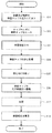
図5、図6、図10〜図17を参照して、検査装置1および検査チップ40を用いた検査方法について説明する。以下の説明では、図10を参照して検査者の動作および検査装置1の動作を説明しつつ、図5、図6、図11〜図17を適宜参照して検査チップ40の状態変化を説明する。   The inspection method using the inspection apparatus 1 and the inspection chip 40 will be described with reference to FIGS. 5, 6, and 10 to 17. In the following description, the state change of the inspection chip 40 will be described with reference to FIGS. 5, 6, and 11 to 17 as appropriate while explaining the operation of the inspector and the operation of the inspection apparatus 1 with reference to FIG. 10. To do.

まず、検査者は検査チップ40の検体投入口41に検体を滴下する。同様に、検査者は、第一試薬投入口42に第一試薬を滴下し、第二試薬投入口43に第二試薬を滴下し、第三試薬投入口44に第三試薬を滴下する(S11)。これにより、検体および第一試薬〜第三試薬が、検査チップ40内に供給される(図11参照)。   First, the examiner drops a sample into the sample insertion port 41 of the test chip 40. Similarly, the examiner drops the first reagent into the first reagent inlet 42, drops the second reagent into the second reagent inlet 43, and drops the third reagent into the third reagent inlet 44 (S11). ). As a result, the specimen and the first to third reagents are supplied into the test chip 40 (see FIG. 11).

ステップS11の実行後、検査者は、検査チップ40の前後方向が遠心力方向と一致するように、且つ、検査チップ40の前側および後側が遠心力方向の上流側および下流側とそれぞれ一致するように、検査チップ40をチップホルダ4にセットする(S12)。次に検査者は、制御装置70の操作部(図示外)を操作して、検査装置1の電源をONする(S13)。制御装置70のCPU(図示外)は、ROM(図示外)に記憶されている制御プログラムに基づいて、検査チップ40の遠心処理を実行する(S14)。   After the execution of step S11, the inspector ensures that the front-rear direction of the test chip 40 matches the centrifugal force direction, and the front side and the rear side of the test chip 40 match the upstream side and the downstream side of the centrifugal force direction, respectively. Then, the inspection chip 40 is set in the chip holder 4 (S12). Next, the inspector operates the operation unit (not shown) of the control device 70 to turn on the power of the inspection device 1 (S13). The CPU (not shown) of the control device 70 executes the centrifuge processing of the test chip 40 based on the control program stored in the ROM (not shown) (S14).

検査チップ40の遠心処理(S14)では、まず検査チップ40の前後方向(検体供給路46、第一試薬供給路47、第二試薬供給路48、第三試薬供給路49の延設方向)と遠心力方向とのなす角度が「0°」の状態で、200Gの遠心力が付与される公転が10秒間行われる。このとき、検査チップ40の後側が、遠心力方向の下流側となる。これにより、図5および図12に示すように、検体投入口41から投入された検体は、遠心力によって検体供給路46を経由して計量部50に流出する。計量部50では、先述したように、所定量の検体が貯留され、且つ、余剰分の検体が余剰槽54に流出して貯留される。   In the centrifugation process (S14) of the test chip 40, first, the front-rear direction of the test chip 40 (the extending direction of the specimen supply path 46, the first reagent supply path 47, the second reagent supply path 48, and the third reagent supply path 49) and In a state where the angle formed with the direction of the centrifugal force is “0 °”, a revolution in which a centrifugal force of 200 G is applied is performed for 10 seconds. At this time, the rear side of the inspection chip 40 is the downstream side in the centrifugal force direction. As a result, as shown in FIGS. 5 and 12, the sample input from the sample input port 41 flows out to the measuring unit 50 via the sample supply path 46 by centrifugal force. In the measuring unit 50, as described above, a predetermined amount of specimen is stored, and a surplus specimen flows out into the surplus tank 54 and stored.

同時に、第一試薬投入口42から投入された第一試薬は、遠心力により第一試薬供給路47を経由して第一混合槽55に流出する。第二試薬投入口43から投入された第二試薬は、遠心力により第二試薬供給路48を経由して第二混合槽57に流出する。第三試薬投入口44から投入された第三試薬は、遠心力により第三試薬供給路49を経由して第三混合槽59に流出する。なお、第一試薬、第二試薬、および第三試薬は、それぞれ遠心力の作用によって第一混合槽55、第二混合槽57、および第三混合槽59に貯留される。   At the same time, the first reagent introduced from the first reagent introduction port 42 flows out to the first mixing tank 55 via the first reagent supply path 47 by centrifugal force. The second reagent introduced from the second reagent introduction port 43 flows out to the second mixing tank 57 via the second reagent supply path 48 by centrifugal force. The third reagent introduced from the third reagent introduction port 44 flows out to the third mixing tank 59 via the third reagent supply path 49 by centrifugal force. The first reagent, the second reagent, and the third reagent are stored in the first mixing tank 55, the second mixing tank 57, and the third mixing tank 59, respectively, by the action of centrifugal force.

次に、チップホルダ4が所定角度自転される。具体的には、図13に示すように、遠心力方向の角度が「30°」となるまで、チップホルダ4が反時計回りに自転される。この状態で、200Gの遠心力が付与される公転が10秒間行われる。このとき、遠心力方向の下流側は、図12に示す例と比較して時計回りに30°傾斜する。検査チップ40の前後方向と壁面52Aの延設方向とのなす角のうち、計量部50側の角度θ12は鈍角になるため、計量部50で計り取られた検体は壁面52Aに沿って先端側に移動し(つまり、第一流路61内を移動し)、第一混合槽55に流れ込む。   Next, the tip holder 4 is rotated by a predetermined angle. Specifically, as shown in FIG. 13, the tip holder 4 rotates counterclockwise until the angle in the centrifugal force direction becomes “30 °”. In this state, a revolution to which a centrifugal force of 200 G is applied is performed for 10 seconds. At this time, the downstream side in the centrifugal force direction is inclined 30 ° clockwise compared to the example shown in FIG. Of the angles formed by the front-rear direction of the test chip 40 and the extending direction of the wall surface 52A, the angle θ12 on the weighing unit 50 side is an obtuse angle, so the sample measured by the weighing unit 50 is on the distal side along the wall surface 52A. (That is, moves in the first flow path 61) and flows into the first mixing tank 55.

ただし、図13に示す状態では、遠心力方向と壁面56Aの延設方向とのなす角のうち、第一混合槽55側の角度θ13は鋭角である。よって、第一混合槽55では、貯留されている第一試薬と第一流路61から流れ込んだ検体とが混合されて、第一混合液が生成および貯留される。同様に、遠心力方向と壁面58Aの延設方向とのなす角のうち、第二混合槽57側の角度θ14は鋭角である。よって、第二混合槽57では、第二試薬が貯留された状態が維持される。   However, in the state shown in FIG. 13, the angle θ13 on the first mixing tank 55 side is an acute angle among the angles formed by the centrifugal force direction and the extending direction of the wall surface 56A. Therefore, in the 1st mixing tank 55, the stored 1st reagent and the sample which flowed in from the 1st flow path 61 are mixed, and a 1st liquid mixture is produced | generated and stored. Similarly, among the angles formed by the centrifugal force direction and the extending direction of the wall surface 58A, the angle θ14 on the second mixing tank 57 side is an acute angle. Therefore, in the second mixing tank 57, the state in which the second reagent is stored is maintained.

次に、チップホルダ4が所定角度自転される。具体的には、図14に示すように、遠心力方向の角度が「60°」となるまで、チップホルダ4が反時計回りに自転される。この状態で、200Gの遠心力が付与される公転が10秒間行われる。このとき、遠心力方向の下流側は、図12に示す例と比較して時計回りに60°傾斜する。角度θ13は鈍角になるため、第一混合槽55で生成された第一混合液は壁面56Aに沿って先端側に移動し(つまり、第二流路62内を移動し)、第二混合槽57に流れ込む。ただし、図14に示す状態では、角度θ14は鋭角である。よって、第二混合槽57では、貯留されている第二試薬と第二流路62から流れ込んだ第一混合液とが混合されて、第二混合液が生成および貯留される。   Next, the tip holder 4 is rotated by a predetermined angle. Specifically, as shown in FIG. 14, the tip holder 4 is rotated counterclockwise until the angle in the centrifugal force direction becomes “60 °”. In this state, a revolution to which a centrifugal force of 200 G is applied is performed for 10 seconds. At this time, the downstream side in the centrifugal force direction is inclined 60 ° clockwise compared to the example shown in FIG. Since the angle θ13 becomes an obtuse angle, the first mixed liquid generated in the first mixing tank 55 moves to the tip side along the wall surface 56A (that is, moves in the second flow path 62), and the second mixing tank Flow into 57. However, in the state shown in FIG. 14, the angle θ14 is an acute angle. Therefore, in the second mixing tank 57, the stored second reagent and the first mixed liquid flowing in from the second flow path 62 are mixed to generate and store the second mixed liquid.

次に、チップホルダ4が所定角度自転される。具体的には、図6および図15に示すように、遠心力方向の角度が「90°」となるまで、チップホルダ4が反時計回りに自転される。この状態で、200Gの遠心力が付与される公転が10秒間行われる。このとき、遠心力方向の下流側は、図12に示す例と比較して時計回りに90°傾斜する。角度θ14は鈍角になるため、第二混合槽57で生成された第二混合液は壁面58Aに沿って先端側に移動し(つまり、第三流路63内を移動し)、第三混合槽59に流れ込む。第三混合槽59では、貯留されている第三試薬と第三流路63から流れ込んだ第二混合液とが混合されて、第三混合液が生成および貯留される。   Next, the tip holder 4 is rotated by a predetermined angle. Specifically, as shown in FIGS. 6 and 15, the tip holder 4 rotates counterclockwise until the angle in the centrifugal force direction becomes “90 °”. In this state, a revolution to which a centrifugal force of 200 G is applied is performed for 10 seconds. At this time, the downstream side in the centrifugal force direction is inclined 90 ° clockwise compared to the example shown in FIG. Since the angle θ14 becomes an obtuse angle, the second mixed liquid generated in the second mixing tank 57 moves along the wall surface 58A to the tip side (that is, moves in the third flow path 63), and the third mixing tank It flows into 59. In the third mixing tank 59, the stored third reagent and the second mixed solution flowing in from the third flow path 63 are mixed to generate and store a third mixed solution.

本実施形態では、遠心力方向の角度が「0°」、「30°」、「60°」、「90°」のいずれであっても、案内面53は遠心力方向と直交する垂直面に対して遠心力方向の下流側に傾斜している(つまり、第五角度θ5は少なくとも「0°」よりも大である)。これにより、上記のように遠心力が付与された場合には、遠心力方向に拘わらず余剰分の検体が案内面53に残存することが抑制される。したがって、余剰分の検体を確実に余剰槽54へ案内しつつ、検体およびその混合液を規定の流路に流出させることができる。さらに、第五角度θ5は遠心力方向に拘わらず「15°」以上であるため、先述の実験データに示すように、検体の粘度に拘わらず案内面53に対する検体の液乗りを防止可能である。   In this embodiment, even if the angle in the centrifugal force direction is “0 °”, “30 °”, “60 °”, or “90 °”, the guide surface 53 is in a vertical plane orthogonal to the centrifugal force direction. On the other hand, it is inclined downstream in the centrifugal force direction (that is, the fifth angle θ5 is at least larger than “0 °”). Thereby, when the centrifugal force is applied as described above, it is possible to suppress the surplus specimen from remaining on the guide surface 53 regardless of the centrifugal force direction. Therefore, the specimen and the liquid mixture thereof can be discharged to the prescribed flow path while reliably guiding the surplus specimen to the surplus tank 54. Furthermore, since the fifth angle θ5 is “15 °” or more regardless of the centrifugal force direction, it is possible to prevent the specimen from riding on the guide surface 53 regardless of the viscosity of the specimen, as shown in the above-described experimental data. .

なお、案内面53は、少なくとも計量部50から第一流路61に検体を流出させる遠心力方向と直交する垂直面に対して、遠心力方向の下流側に傾斜していればよい。具体的には、遠心力方向の角度が「30°」である場合に(図13参照)、第五角度θ5が少なくとも「0°」よりも大であればよい。つまり、平面視で案内面53の延設方向に延びる線と検査チップ40の左右方向に延びる線との交点を回転中心として、案内面53を左右方向と平行になるまで反時計回り方向に回転させた場合の角度が、少なくとも「30°」よりも大であればよい。   In addition, the guide surface 53 should just incline in the downstream of a centrifugal force direction with respect to the perpendicular surface orthogonal to the centrifugal force direction which makes a 1st flow path 61 flow out of a test substance at least. Specifically, when the angle in the centrifugal force direction is “30 °” (see FIG. 13), the fifth angle θ5 only needs to be at least larger than “0 °”. In other words, the guide surface 53 is rotated counterclockwise until the guide surface 53 is parallel to the left-right direction, with the intersection point between the line extending in the extending direction of the guide surface 53 and the line extending in the left-right direction of the inspection chip 40 in plan view. The angle in the case of making it should just be larger than "30 degree" at least.

これにより、案内面53に検体が残留している状態で、遠心力方向の角度が「0°」(図12参照)から「30°」(図13参照)に変化した場合でも、残留している検体が案内面53を逆流しにくいため、不要な検体が計量部50に混入することを抑制できる。さらに、計量部50で計量されている検体が案内面53に流出しにくいので、計量部50で形成されている検体のメニスカスが崩れてしまうことを抑制できる。ひいては、計量部50における検体の計量誤差を低減できる。   Accordingly, even when the specimen remains on the guide surface 53 and the angle in the centrifugal force direction changes from “0 °” (see FIG. 12) to “30 °” (see FIG. 13), it remains. Since it is difficult for the sample to flow back through the guide surface 53, it is possible to suppress the unnecessary sample from being mixed into the measuring unit 50. Furthermore, since the sample weighed by the weighing unit 50 does not easily flow out to the guide surface 53, it is possible to prevent the meniscus of the sample formed by the weighing unit 50 from being broken. As a result, the measurement error of the sample in the measurement part 50 can be reduced.

最後に、チップホルダ4が元の状態に戻るように自転される。具体的には、図17に示すように、遠心力方向の角度が「0°」となるまで、チップホルダ4が時計回りに自転される。この状態で、200Gの遠心力が付与される公転が10秒間行われる。このとき、遠心力方向の下流側は、図5および図12に示す例と同様に、検査チップ40の後側と一致する。遠心力の作用によって、第三混合液が第三混合槽59の下部に攪拌されながら溜まる。   Finally, the tip holder 4 is rotated so as to return to the original state. Specifically, as shown in FIG. 17, the tip holder 4 rotates clockwise until the angle in the centrifugal force direction becomes “0 °”. In this state, a revolution to which a centrifugal force of 200 G is applied is performed for 10 seconds. At this time, the downstream side in the centrifugal force direction coincides with the rear side of the test chip 40 as in the example shown in FIGS. Due to the action of the centrifugal force, the third mixed liquid accumulates in the lower part of the third mixing tank 59 while being stirred.

ステップS14の実行後、ターンテーブル3の回転(つまり、チップホルダ4の公転)が停止され、遠心力の付加が終了される(S15)。このとき、検査チップ40を光学検査部に位置させるように、ターンテーブル3を所定の回転位置で停止させる(S16)。光学検査部は、上下方向に対向する光源7と検出器8との間で、検査チップ40を検査する部位である。ステップS16の実行後、光源7から検査チップ40に対して光が照射される。検出器8で検査チップ40を透過した光が検出されることによって、検査結果が測定される(S17)。最後に、ステップS17で測定された検査結果が、制御装置70の画面(図示外)に表示される(S18)。   After execution of step S14, the rotation of the turntable 3 (that is, the revolution of the chip holder 4) is stopped, and the application of centrifugal force is terminated (S15). At this time, the turntable 3 is stopped at a predetermined rotational position so that the inspection chip 40 is positioned in the optical inspection section (S16). The optical inspection unit is a part that inspects the inspection chip 40 between the light source 7 and the detector 8 facing in the vertical direction. After execution of step S16, light is emitted from the light source 7 to the inspection chip 40. By detecting the light transmitted through the inspection chip 40 by the detector 8, the inspection result is measured (S17). Finally, the inspection result measured in step S17 is displayed on the screen (not shown) of the control device 70 (S18).

以上説明したように、本実施形態に係る検査チップ40によれば、検体に「0°」の遠心力が付与された場合、検体投入口41から供給された検体が検体供給路46によって計量部50へ案内されて、計量部50で所定量の検体が貯留される。計量部50から流出する余剰分の検体は、検査に使用されない不要な検体であるため、案内面53によって余剰槽54へ案内されて、余剰槽54に収容される。案内面53は、計量部50における余剰槽54側の端部から、計量部50に貯留されている検体を第一流路61に流出させる際に付加される遠心力方向と直交する垂直面に対して下流側に傾斜している。したがって、案内面53に検体が残留している状態で「30°」の遠心力が付与された場合でも、残留している検体は案内面53を逆流しにくいため、不要な検体が計量部50に混入することを抑制できる。   As described above, according to the test chip 40 according to the present embodiment, when a centrifugal force of “0 °” is applied to the sample, the sample supplied from the sample inlet 41 is measured by the sample supply path 46 through the measuring unit. 50, the measuring unit 50 stores a predetermined amount of specimen. Since the surplus specimen flowing out from the measuring unit 50 is an unnecessary specimen that is not used for the examination, it is guided to the surplus tank 54 by the guide surface 53 and stored in the surplus tank 54. The guide surface 53 is relative to a vertical plane orthogonal to the direction of the centrifugal force applied when the sample stored in the measuring unit 50 flows out from the end on the surplus tank 54 side of the measuring unit 50 to the first flow path 61. And tilted downstream. Therefore, even when a centrifugal force of “30 °” is applied with the specimen remaining on the guide surface 53, the remaining specimen is unlikely to flow back through the guide surface 53, so an unnecessary specimen is placed in the weighing unit 50. It can suppress mixing in.

上記実施形態において、軸6が本発明の「回転軸」に相当し、検体が本発明の「検査対象の液体」に相当し、検査チップ40が本発明の「検査対象受体」に相当する。検体投入口41が、本発明の「供給口」に相当する。検体供給路46が、本発明の「第一案内部」に相当する。計量部50が、本発明の「液受部」に相当する。案内面53が、本発明の「第二案内部」に相当する。余剰槽54が、本発明の「余剰部」に相当する。第五角度θ5が、本発明の「角度θ」に相当する。   In the above embodiment, the shaft 6 corresponds to the “rotating shaft” of the present invention, the specimen corresponds to the “liquid to be tested” of the present invention, and the test chip 40 corresponds to the “test target receiver” of the present invention. . The sample insertion port 41 corresponds to the “supply port” of the present invention. The sample supply path 46 corresponds to the “first guide part” of the present invention. The measuring unit 50 corresponds to the “liquid receiving unit” of the present invention. The guide surface 53 corresponds to the “second guide portion” of the present invention. The surplus tank 54 corresponds to the “surplus part” of the present invention. The fifth angle θ5 corresponds to the “angle θ” of the present invention.

なお、本発明は、上記実施形態に限定されるものではなく、各種の変形が可能なことはいうまでもない。例えば、図17および図18に示すように、検体の遠心分離を行う検査チップ80に、本発明を適用してもよい。以下では、図17および図18の上方、下方、右方、左方を、それぞれ、検査チップ80の前方、後方、右方、左方として説明する。また、図17および図18の紙面手前側および紙面奥側を、それぞれ、検査チップ80の上方および下方として説明する。なお、後述の第六角度θ6は、第五角度θ5と同様に、上述の実験データ(図7〜図9参照)に基づいて決定することができる。   Needless to say, the present invention is not limited to the above embodiment, and various modifications are possible. For example, as shown in FIGS. 17 and 18, the present invention may be applied to a test chip 80 that centrifuges a specimen. Hereinafter, the upper, lower, right, and left sides in FIGS. 17 and 18 will be described as the front, rear, right, and left sides of the test chip 80, respectively. Further, the front side and the back side of the drawing in FIGS. 17 and 18 will be described as being above and below the inspection chip 80, respectively. Note that the hexagonal degree θ6 described later can be determined based on the above-described experimental data (see FIGS. 7 to 9), similarly to the fifth angle θ5.

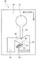
図17および図18に示す検査チップ80は、上記の検査チップ40と同様に、所定の厚みを有する合成樹脂の板材89によって外形が構成されている。検体投入口81が、板材89に平面視円形の窪みとして形成されている。図示しないが、検査チップ80の上面は、検体投入口81と対応する位置のみに開口が形成された透明の合成樹脂製の蓋(図示外)で覆われている。また、検体供給路82が、板材89に溝状に形成されている。検体供給路82の後端部には、幅が狭くなった出口が設けられている。検体供給路82の後方側には、検体供給路82から供給される検体を遠心分離するための遠心分離部90が形成されている。遠心分離部90は、平面視で左後方にU字型に凹む部位である。   The outer shape of the inspection chip 80 shown in FIGS. 17 and 18 is configured by a synthetic resin plate material 89 having a predetermined thickness, similarly to the inspection chip 40 described above. A specimen insertion port 81 is formed in the plate member 89 as a circular recess in plan view. Although not shown, the upper surface of the test chip 80 is covered with a transparent synthetic resin lid (not shown) in which an opening is formed only at a position corresponding to the sample insertion port 81. A sample supply path 82 is formed in the plate material 89 in a groove shape. An outlet having a narrow width is provided at the rear end of the sample supply path 82. A centrifuge 90 for centrifuging the sample supplied from the sample supply path 82 is formed on the rear side of the sample supply path 82. The centrifuge 90 is a portion that is recessed in a U-shape to the left rear in plan view.

遠心分離部90の開口縁の一端側(図17では左端側)から左前方に向けて、第二流路85が板材89に溝状に形成されている。第二流路85は、遠心分離部90で分離された検体の上澄み液を、検査槽86へ案内する流路である。検査槽86は、平面視で後方に凹む部位であって、第二流路85を案内された上澄み液が貯留される。一方、遠心分離部90の開口縁の他端側(図17では右端側)から後方に向けて、第一流路84が板材89に溝状に形成されている。第一流路84は、遠心分離部90から流れ出た検体(すなわち、余った検体)を、余剰槽83へ案内する流路である。余剰槽83は、遠心分離部90よりも後方に設けられた、平面視で後方に凹む部位であって、第一流路84を案内された検体が貯留される。   A second flow path 85 is formed in the plate material 89 in a groove shape from one end side (left end side in FIG. 17) of the opening edge of the centrifuge 90 toward the left front. The second flow path 85 is a flow path for guiding the supernatant of the specimen separated by the centrifuge 90 to the test tank 86. The inspection tank 86 is a portion recessed rearward in a plan view, and the supernatant liquid guided through the second flow path 85 is stored. On the other hand, the first flow path 84 is formed in the plate material 89 in a groove shape from the other end side (the right end side in FIG. 17) of the opening edge of the centrifuge 90 to the rear. The first flow path 84 is a flow path that guides the specimen flowing out from the centrifuge 90 (that is, the surplus specimen) to the surplus tank 83. The surplus tank 83 is a portion that is provided behind the centrifuge 90 and is recessed rearward in plan view, and stores the specimen guided through the first flow path 84.

遠心分離部90の余剰槽83側の端部から後方に連続して延びる壁面は、案内面93である。案内面93は、第一流路84に流れ出た検体を余剰槽83に向けて案内する。案内面93の延設方向と、検査チップ80に付与される遠心力の方向と直交する垂直面とのなす角度は、第六角度θ6である。より詳細には、第六角度θ6は、平面視で案内面93の延設方向に延びる線と遠心力方向と直交する垂直線との交点を回転中心として、案内面93をこの垂直線と平行になるまで反時計回り方向に回転させた場合の角度である。案内面93は、遠心力方向と直交する垂直面に対して遠心力方向の下流側に傾斜するように延びているため、第六角度θ6は少なくとも0°よりも大である。   A wall surface continuously extending rearward from the end of the centrifugal separator 90 on the surplus tank 83 side is a guide surface 93. The guide surface 93 guides the specimen that has flowed into the first flow path 84 toward the surplus tank 83. The angle formed by the extending direction of the guide surface 93 and the vertical plane orthogonal to the direction of the centrifugal force applied to the test chip 80 is the sixth hexagonal degree θ6. More specifically, the sixth hexagonal degree θ6 has the guide surface 93 parallel to the vertical line with the intersection point between a line extending in the extending direction of the guide surface 93 and a vertical line orthogonal to the centrifugal force direction as viewed in plan view. This is the angle when rotated counterclockwise until Since the guide surface 93 extends so as to incline toward the downstream side in the centrifugal force direction with respect to the vertical plane orthogonal to the centrifugal force direction, the sixth hexagonal degree θ6 is at least greater than 0 °.

第六角度θ6の大きさは、検査チップ80に付与される遠心力の方向に応じて変化する。具体的には、図17に示すように、検査チップ80の前側から後方に向けて遠心力が作用している場合は、第六角度θ6は案内面93の延設方向と検査チップ80の左右方向とのなす角度となる。一方、図18に示すように、検査チップ80の右側から左方に向けて遠心力が作用している場合は、第六角度θ6は案内面93の延設方向と検査チップ80の前後方向とのなす角度となる。   The magnitude of the sixth hexagonal degree θ6 varies depending on the direction of the centrifugal force applied to the inspection chip 80. Specifically, as shown in FIG. 17, when a centrifugal force is applied from the front side to the rear side of the test chip 80, the sixth hexagonal degree θ 6 is determined by the extending direction of the guide surface 93 and the left and right sides of the test chip 80. It is the angle made with the direction. On the other hand, as shown in FIG. 18, when a centrifugal force is acting from the right side to the left side of the test chip 80, the sixth hexagonal degree θ6 is determined by the extending direction of the guide surface 93 and the front-back direction of the test chip 80 The angle formed by

後述するように、検査装置1の遠心処理時には、遠心力方向の角度が「0°」(図17参照)から「90°」(図18参照)まで変化するように、検査チップ80が適宜回転される。遠心力方向の角度が大きいほど、第六角度θ6は小さくなる。さらに、検査チップ80では、第六角度θ6が最も小さくなる遠心状態でも案内面93の液乗りが防止されるように、遠心力方向の角度が「90°」の場合を基準として、第六角度θ6が「15°」以上となるように設定されている。具体的には、案内面93の延設方向と検査チップ80の前後方向とのなす角度が「15°」となるように、案内面93の傾斜が規定されている。   As will be described later, when the inspection apparatus 1 is centrifuged, the inspection chip 80 is appropriately rotated so that the angle in the centrifugal force direction changes from “0 °” (see FIG. 17) to “90 °” (see FIG. 18). Is done. The greater the angle in the direction of centrifugal force, the smaller the hexagonal degree θ6. Further, in the inspection chip 80, the hexagonal degree is determined based on the case where the angle in the centrifugal force direction is “90 °” so that the guide surface 93 is prevented from riding in the centrifugal state where the hexagonal degree θ6 is the smallest. θ6 is set to be “15 °” or more. Specifically, the inclination of the guide surface 93 is defined so that the angle formed by the extending direction of the guide surface 93 and the front-rear direction of the inspection chip 80 is “15 °”.

検査装置1および検査チップ80を用いた検査方法は、図10と同様である。まず、検査者は検査チップ80の検体投入口81に検体を滴下して(S11)、検査チップ80をチップホルダ4にセットする(S12)。次に、検査者が検査装置1の電源をONすると(S13)、検査チップ80の遠心処理が実行される(S14)。   The inspection method using the inspection apparatus 1 and the inspection chip 80 is the same as that in FIG. First, the examiner drops a sample into the sample insertion port 81 of the test chip 80 (S11), and sets the test chip 80 in the chip holder 4 (S12). Next, when the inspector turns on the power of the inspection apparatus 1 (S13), the centrifuge processing of the inspection chip 80 is executed (S14).

検査チップ80の遠心処理(S14)では、まず遠心力方向の角度が「0°」の状態で、200Gの遠心力が付与される公転が10秒間行われる。このとき、検査チップ80の後側が、遠心力方向の下流側となる。これにより、図17に示すように、検体投入口81から投入された検体は、遠心力によって検体供給路82を経由して遠心分離部90に流出する。遠心分離部90では、所定量まで検体が貯留され、且つ、余剰分の検体が余剰槽83に流出して貯留される。さらに、遠心分離部90では、遠心力の作用によって、貯留されている検体が遠心分離される。   In the centrifugation process (S14) of the inspection chip 80, first, a revolution in which a centrifugal force of 200 G is applied is performed for 10 seconds in a state where the angle in the centrifugal force direction is “0 °”. At this time, the rear side of the inspection chip 80 is the downstream side in the centrifugal force direction. As a result, as shown in FIG. 17, the sample input from the sample input port 81 flows out to the centrifuge 90 through the sample supply path 82 by centrifugal force. In the centrifuge 90, the specimen is stored up to a predetermined amount, and the surplus specimen flows out into the surplus tank 83 and stored. Further, in the centrifuge 90, the stored specimen is centrifuged by the action of centrifugal force.

次に、チップホルダ4が所定角度自転される。具体的には、図18に示すように、遠心力方向の角度が「90°」となるまで、チップホルダ4が反時計回りに自転される。この状態で、200Gの遠心力が付与される公転が10秒間行われる。このとき、遠心力方向の下流側は、図17に示す例と比較して時計回りに90°傾斜する。そして、遠心分離部90に貯留されている検体のうち、上澄み液のみが第二流路85に流出して、検査槽86に流れ込む。   Next, the tip holder 4 is rotated by a predetermined angle. Specifically, as shown in FIG. 18, the tip holder 4 rotates counterclockwise until the angle in the centrifugal force direction becomes “90 °”. In this state, a revolution to which a centrifugal force of 200 G is applied is performed for 10 seconds. At this time, the downstream side in the centrifugal force direction is inclined 90 ° clockwise compared to the example shown in FIG. Of the specimens stored in the centrifugal separator 90, only the supernatant liquid flows out into the second flow path 85 and flows into the inspection tank 86.

最後に、遠心力方向の角度が「0°」となるまで、チップホルダ4が時計回りに自転される。この状態で、200Gの遠心力が付与される公転が10秒間行われる。遠心力の作用によって、検体の上澄み液が検査槽86の下部に溜まる。ステップS14の実行後、ターンテーブル3の回転(つまり、チップホルダ4の公転)が停止され、遠心力の付加が終了される(S15)。このとき、検査チップ80を光学検査部に位置させるように、ターンテーブル3が所定の回転位置で停止される(S16)。ステップS16の実行後、検査結果の測定および表示が行われる(S17、S18)。   Finally, the tip holder 4 is rotated clockwise until the angle in the centrifugal force direction becomes “0 °”. In this state, a revolution to which a centrifugal force of 200 G is applied is performed for 10 seconds. Due to the action of the centrifugal force, the supernatant of the specimen accumulates in the lower part of the inspection tank 86. After execution of step S14, the rotation of the turntable 3 (that is, the revolution of the chip holder 4) is stopped, and the application of centrifugal force is terminated (S15). At this time, the turntable 3 is stopped at a predetermined rotational position so that the inspection chip 80 is positioned on the optical inspection unit (S16). After execution of step S16, measurement and display of the inspection result is performed (S17, S18).

上記の検査チップ80では、遠心力方向の角度が「0°」および「90°」のいずれであっても、案内面93は遠心力方向と直交する垂直面に対して遠心力方向の下流側に傾斜している(つまり、第六角度θ6は少なくとも「0°」よりも大である)。より詳細には、案内面93は、遠心分離部90から第二流路85に上澄み液を流出させる遠心力方向と直交する垂直面に対して、遠心力方向の下流側に傾斜している。具体的には、遠心力方向の角度が「90°」である場合に(図18参照)、第六角度θ6が少なくとも「0°」よりも大である。   In the inspection chip 80 described above, the guide surface 93 is downstream in the centrifugal force direction with respect to the vertical plane orthogonal to the centrifugal force direction, regardless of whether the angle in the centrifugal force direction is “0 °” or “90 °”. (Ie, the hexagonal degree θ6 is at least greater than “0 °”). More specifically, the guide surface 93 is inclined to the downstream side in the centrifugal force direction with respect to a vertical surface orthogonal to the centrifugal force direction that causes the supernatant liquid to flow out from the centrifugal separator 90 to the second flow path 85. Specifically, when the angle in the centrifugal force direction is “90 °” (see FIG. 18), the sixth hexagonal degree θ6 is at least larger than “0 °”.

これにより、案内面93に検体が残留している状態で、遠心力方向の角度が「0°」(図12参照)から「30°」(図13参照)に変化した場合でも、残留している検体が案内面53を逆流しにくいため、不要な検体が計量部50に混入することを抑制できる。さらに、検査チップ80では、第六角度θ6が遠心力方向に拘わらず「15°」以上であるため、先述の実験データに示すように、検体の粘度に拘わらず案内面93に対する検体の液乗りを防止可能である。   As a result, even when the specimen remains on the guide surface 93 and the angle in the centrifugal force direction changes from “0 °” (see FIG. 12) to “30 °” (see FIG. 13), it remains. Since it is difficult for the sample to flow back through the guide surface 53, it is possible to suppress the unnecessary sample from being mixed into the measuring unit 50. Further, in the test chip 80, since the sixth hexagonal degree θ6 is “15 °” or more regardless of the centrifugal force direction, as shown in the above-mentioned experimental data, the liquid level of the sample on the guide surface 93 regardless of the viscosity of the sample. Can be prevented.

1 検査装置
3 ターンテーブル
4 チップホルダ
6 軸
19 角度変更機構
40 検査チップ
41 検体投入口
46 検体供給路
50 計量部
51 第一壁部
51A 壁面
52 第二壁部
52A 壁面
53 案内面
54 余剰槽
80 検査チップ
90 遠心分離部
DESCRIPTION OF SYMBOLS 1 Inspection apparatus 3 Turntable 4 Tip holder 6 Axis 19 Angle change mechanism 40 Inspection chip 41 Specimen inlet 46 Specimen supply path 50 Weighing part 51 First wall part 51A Wall surface 52 Second wall part 52A Wall surface 53 Guide surface 54 Surplus tank 80 Inspection chip 90 Centrifuge section

Claims (4)

回転軸から離間した位置で回転自在に保持され、且つ、前記回転軸を中心とした回転時に生じる遠心力によって検査対象の液体を検査する検査対象受体であって、
前記検査対象受体の内部に前記液体を供給するための供給口と、
前記遠心力が第一の方向に生じている場合に、前記供給口から供給された前記液体を前記第一の方向の下流側に案内する第一案内部と、
前記第一案内部を案内された前記液体を受けて、所定量の前記液体を貯留可能な凹部である液受部と、
前記液受部で前記所定量の前記液体が貯留され、且つ、前記遠心力が第一の方向に生じている場合に、前記液受部から流出する余剰分の前記液体を前記第一の方向の下流側に案内する第二案内部と、
前記液受部よりも前記第一の方向の下流側に設けられ、前記第二案内部によって案内された前記余剰分の前記液体が貯留される余剰部とを備え、
前記第二案内部は、前記液受部における前記余剰部側の端部から延びる壁面であり、且つ、前記液受部に貯留されている前記液体を前記余剰部とは異なる所定の箇所に流出させる際に付加される前記遠心力の方向である第二の方向と直交する垂直面に対して、前記第二の方向の下流側に傾斜するように延びることを特徴とする検査対象受体。
An inspection object receiver that is rotatably held at a position separated from a rotation axis and inspects a liquid to be inspected by a centrifugal force generated at the time of rotation about the rotation axis,
A supply port for supplying the liquid to the inside of the test object receptacle;
A first guide portion for guiding the liquid supplied from the supply port to the downstream side in the first direction when the centrifugal force is generated in the first direction;
Receiving the liquid guided through the first guide part, and a liquid receiving part that is a recess capable of storing a predetermined amount of the liquid;
When the predetermined amount of the liquid is stored in the liquid receiving portion and the centrifugal force is generated in the first direction, the excess liquid flowing out from the liquid receiving portion is transferred to the first direction. A second guide portion for guiding to the downstream side of
A surplus part that is provided downstream of the liquid receiving part in the first direction and stores the surplus liquid guided by the second guide part;
The second guide portion is a wall surface extending from an end of the liquid receiving portion on the surplus portion side, and the liquid stored in the liquid receiving portion flows out to a predetermined location different from the surplus portion. A test object receiver, which extends so as to incline toward the downstream side of the second direction with respect to a vertical plane orthogonal to the second direction, which is the direction of the centrifugal force applied when performing the operation.
前記第二案内部と前記垂直面とのなす角のうち、前記垂直面を前記第二案内部と対向する側から前記第二案内部まで回転させた場合の角度θは、少なくとも5°以上であることを特徴とする請求項1に記載の検査対象受体。   Of the angles formed by the second guide portion and the vertical surface, the angle θ when the vertical surface is rotated from the side facing the second guide portion to the second guide portion is at least 5 ° or more. The test object receiver according to claim 1, wherein the test object receiver is provided. 前記角度θは、前記液体の粘度が1cP未満である場合、10°以上であることを特徴とする請求項2に記載の検査対象受体。   The inspection object receptacle according to claim 2, wherein the angle θ is 10 ° or more when the viscosity of the liquid is less than 1 cP. 前記角度θは、前記液体の粘度が1cP以上である場合、15°以上であることを特徴とする請求項2に記載の検査対象受体。   The inspection object receptacle according to claim 2, wherein the angle θ is 15 ° or more when the viscosity of the liquid is 1 cP or more.
JP2010110153A 2010-05-12 2010-05-12 Inspection target Expired - Fee Related JP5359987B2 (en)

Priority Applications (1)

Application Number Priority Date Filing Date Title
JP2010110153A JP5359987B2 (en) 2010-05-12 2010-05-12 Inspection target

Applications Claiming Priority (1)

Application Number Priority Date Filing Date Title
JP2010110153A JP5359987B2 (en) 2010-05-12 2010-05-12 Inspection target

Publications (2)

Publication Number Publication Date
JP2011237325A true JP2011237325A (en) 2011-11-24
JP5359987B2 JP5359987B2 (en) 2013-12-04

Family

ID=45325466

Family Applications (1)

Application Number Title Priority Date Filing Date
JP2010110153A Expired - Fee Related JP5359987B2 (en) 2010-05-12 2010-05-12 Inspection target

Country Status (1)

Country Link
JP (1) JP5359987B2 (en)

Cited By (8)

* Cited by examiner, † Cited by third party
Publication number Priority date Publication date Assignee Title
WO2013146579A1 (en) * 2012-03-29 2013-10-03 ブラザー工業株式会社 Inspection sample receiving body, inspection device and inspection method
WO2014061636A1 (en) * 2012-10-15 2014-04-24 ブラザー工業株式会社 Inspection chip
WO2014061635A1 (en) * 2012-10-15 2014-04-24 ブラザー工業株式会社 Inspection device, inspection system, inspection method, and computer program
WO2014103865A1 (en) * 2012-12-27 2014-07-03 ブラザー工業株式会社 Inspection chip, and inspection system
JP2015031643A (en) * 2013-08-06 2015-02-16 ブラザー工業株式会社 Inspection chip
JP2015118043A (en) * 2013-12-19 2015-06-25 ブラザー工業株式会社 Inspection device
WO2015152230A1 (en) * 2014-03-31 2015-10-08 ブラザー工業株式会社 Detection chip
JP2015197351A (en) * 2014-03-31 2015-11-09 ブラザー工業株式会社 inspection chip

Citations (8)

* Cited by examiner, † Cited by third party
Publication number Priority date Publication date Assignee Title
JPS60238760A (en) * 1984-05-03 1985-11-27 アボツト ラボラトリーズ Processor-card for centrifugal separator
JP2008101983A (en) * 2006-10-18 2008-05-01 Rohm Co Ltd Chip having measurement section and method of measuring liquid sample using the chip
JP2008164360A (en) * 2006-12-27 2008-07-17 Rohm Co Ltd Method of determining whether liquid quantity and/or quality of liquid reagent in liquid reagent built-in type microchip are/is normal or not, and liquid reagent built-in type microchip
JP2009156765A (en) * 2007-12-27 2009-07-16 Rohm Co Ltd Microchip
JP2009162517A (en) * 2007-12-28 2009-07-23 Rohm Co Ltd Microchip
JP2009276143A (en) * 2008-05-13 2009-11-26 Rohm Co Ltd Microchip
JP2009281869A (en) * 2008-05-22 2009-12-03 Rohm Co Ltd Microchip
JP2009287971A (en) * 2008-05-27 2009-12-10 Rohm Co Ltd Microchip

Patent Citations (8)

* Cited by examiner, † Cited by third party
Publication number Priority date Publication date Assignee Title
JPS60238760A (en) * 1984-05-03 1985-11-27 アボツト ラボラトリーズ Processor-card for centrifugal separator
JP2008101983A (en) * 2006-10-18 2008-05-01 Rohm Co Ltd Chip having measurement section and method of measuring liquid sample using the chip
JP2008164360A (en) * 2006-12-27 2008-07-17 Rohm Co Ltd Method of determining whether liquid quantity and/or quality of liquid reagent in liquid reagent built-in type microchip are/is normal or not, and liquid reagent built-in type microchip
JP2009156765A (en) * 2007-12-27 2009-07-16 Rohm Co Ltd Microchip
JP2009162517A (en) * 2007-12-28 2009-07-23 Rohm Co Ltd Microchip
JP2009276143A (en) * 2008-05-13 2009-11-26 Rohm Co Ltd Microchip
JP2009281869A (en) * 2008-05-22 2009-12-03 Rohm Co Ltd Microchip
JP2009287971A (en) * 2008-05-27 2009-12-10 Rohm Co Ltd Microchip

Cited By (13)

* Cited by examiner, † Cited by third party
Publication number Priority date Publication date Assignee Title
WO2013146579A1 (en) * 2012-03-29 2013-10-03 ブラザー工業株式会社 Inspection sample receiving body, inspection device and inspection method
JP2013205282A (en) * 2012-03-29 2013-10-07 Brother Ind Ltd Inspection object holder, inspection device, and inspection method
WO2014061636A1 (en) * 2012-10-15 2014-04-24 ブラザー工業株式会社 Inspection chip
WO2014061635A1 (en) * 2012-10-15 2014-04-24 ブラザー工業株式会社 Inspection device, inspection system, inspection method, and computer program
JP2014081248A (en) * 2012-10-15 2014-05-08 Brother Ind Ltd Inspection apparatus, inspection system, inspection method and computer program
JP2014081247A (en) * 2012-10-15 2014-05-08 Brother Ind Ltd Inspection chip
WO2014103865A1 (en) * 2012-12-27 2014-07-03 ブラザー工業株式会社 Inspection chip, and inspection system
JP2014126530A (en) * 2012-12-27 2014-07-07 Brother Ind Ltd Inspection chip and inspection system
JP2015031643A (en) * 2013-08-06 2015-02-16 ブラザー工業株式会社 Inspection chip
JP2015118043A (en) * 2013-12-19 2015-06-25 ブラザー工業株式会社 Inspection device
WO2015152230A1 (en) * 2014-03-31 2015-10-08 ブラザー工業株式会社 Detection chip
JP2015197351A (en) * 2014-03-31 2015-11-09 ブラザー工業株式会社 inspection chip
JP2015197350A (en) * 2014-03-31 2015-11-09 ブラザー工業株式会社 Inspection tip

Also Published As

Publication number Publication date
JP5359987B2 (en) 2013-12-04

Similar Documents

Publication Publication Date Title
JP5359987B2 (en) Inspection target
US9199235B2 (en) Test chip
JP5359964B2 (en) Inspection object receiver, inspection apparatus and inspection method
NZ211887A (en) Sample processor card for use with centrifuge
JP2012078115A (en) Inspection object acceptor
JP5459265B2 (en) Inspection target receptacle, liquid mixing system including the inspection target receptacle, and liquid mixing method using the liquid mixing system
JP2012127724A (en) Microchip
JP5267515B2 (en) Inspection target
JP2012202736A (en) Inspection object acceptor, inspection method, and inspection device
WO2015080193A1 (en) Inspection chip
JP2012013553A (en) Inspection object acceptor
JP2009276143A (en) Microchip
JP5843160B2 (en) Inspection object receiver, inspection device, and inspection method
JP2012078094A (en) Inspection object acceptor
JP5958452B2 (en) Inspection chip
JP5958451B2 (en) Inspection chip, liquid feeding method, and liquid feeding program
JP2010145314A (en) Microchip
JP5915686B2 (en) Inspection chip
JP6028720B2 (en) Inspection chip
JP6010967B2 (en) Inspection object receiver, inspection device, and inspection method
JP5408094B2 (en) Inspection target
WO2013146579A1 (en) Inspection sample receiving body, inspection device and inspection method
JP5910657B2 (en) Inspection chip and inspection system
JP2015105888A (en) Inspection device, inspection method, and inspection program
JP2015197351A (en) inspection chip

Legal Events

Date Code Title Description
A621 Written request for application examination

Free format text: JAPANESE INTERMEDIATE CODE: A621

Effective date: 20120313

A977 Report on retrieval

Free format text: JAPANESE INTERMEDIATE CODE: A971007

Effective date: 20121004

A131 Notification of reasons for refusal

Free format text: JAPANESE INTERMEDIATE CODE: A131

Effective date: 20121113

TRDD Decision of grant or rejection written
A01 Written decision to grant a patent or to grant a registration (utility model)

Free format text: JAPANESE INTERMEDIATE CODE: A01

Effective date: 20130806

A61 First payment of annual fees (during grant procedure)

Free format text: JAPANESE INTERMEDIATE CODE: A61

Effective date: 20130819

R150 Certificate of patent or registration of utility model

Free format text: JAPANESE INTERMEDIATE CODE: R150

LAPS Cancellation because of no payment of annual fees