JP2011109902A - Electric power supply system for vehicle - Google Patents
Electric power supply system for vehicle Download PDFInfo
- Publication number
- JP2011109902A JP2011109902A JP2010252236A JP2010252236A JP2011109902A JP 2011109902 A JP2011109902 A JP 2011109902A JP 2010252236 A JP2010252236 A JP 2010252236A JP 2010252236 A JP2010252236 A JP 2010252236A JP 2011109902 A JP2011109902 A JP 2011109902A
- Authority
- JP
- Japan
- Prior art keywords
- power
- vehicle
- antenna
- charging
- power transmission
- Prior art date
- Legal status (The legal status is an assumption and is not a legal conclusion. Google has not performed a legal analysis and makes no representation as to the accuracy of the status listed.)
- Granted
Links
Images


Classifications
-
- H—ELECTRICITY
- H02—GENERATION; CONVERSION OR DISTRIBUTION OF ELECTRIC POWER
- H02J—CIRCUIT ARRANGEMENTS OR SYSTEMS FOR SUPPLYING OR DISTRIBUTING ELECTRIC POWER; SYSTEMS FOR STORING ELECTRIC ENERGY
- H02J7/00—Circuit arrangements for charging or depolarising batteries or for supplying loads from batteries
- H02J7/0068—Battery or charger load switching, e.g. concurrent charging and load supply
-
- B—PERFORMING OPERATIONS; TRANSPORTING
- B60—VEHICLES IN GENERAL
- B60L—PROPULSION OF ELECTRICALLY-PROPELLED VEHICLES; SUPPLYING ELECTRIC POWER FOR AUXILIARY EQUIPMENT OF ELECTRICALLY-PROPELLED VEHICLES; ELECTRODYNAMIC BRAKE SYSTEMS FOR VEHICLES IN GENERAL; MAGNETIC SUSPENSION OR LEVITATION FOR VEHICLES; MONITORING OPERATING VARIABLES OF ELECTRICALLY-PROPELLED VEHICLES; ELECTRIC SAFETY DEVICES FOR ELECTRICALLY-PROPELLED VEHICLES
- B60L5/00—Current collectors for power supply lines of electrically-propelled vehicles
- B60L5/005—Current collectors for power supply lines of electrically-propelled vehicles without mechanical contact between the collector and the power supply line
-
- B—PERFORMING OPERATIONS; TRANSPORTING
- B60—VEHICLES IN GENERAL
- B60L—PROPULSION OF ELECTRICALLY-PROPELLED VEHICLES; SUPPLYING ELECTRIC POWER FOR AUXILIARY EQUIPMENT OF ELECTRICALLY-PROPELLED VEHICLES; ELECTRODYNAMIC BRAKE SYSTEMS FOR VEHICLES IN GENERAL; MAGNETIC SUSPENSION OR LEVITATION FOR VEHICLES; MONITORING OPERATING VARIABLES OF ELECTRICALLY-PROPELLED VEHICLES; ELECTRIC SAFETY DEVICES FOR ELECTRICALLY-PROPELLED VEHICLES
- B60L53/00—Methods of charging batteries, specially adapted for electric vehicles; Charging stations or on-board charging equipment therefor; Exchange of energy storage elements in electric vehicles
- B60L53/10—Methods of charging batteries, specially adapted for electric vehicles; Charging stations or on-board charging equipment therefor; Exchange of energy storage elements in electric vehicles characterised by the energy transfer between the charging station and the vehicle
- B60L53/12—Inductive energy transfer
- B60L53/122—Circuits or methods for driving the primary coil, e.g. supplying electric power to the coil
-
- B—PERFORMING OPERATIONS; TRANSPORTING
- B60—VEHICLES IN GENERAL
- B60L—PROPULSION OF ELECTRICALLY-PROPELLED VEHICLES; SUPPLYING ELECTRIC POWER FOR AUXILIARY EQUIPMENT OF ELECTRICALLY-PROPELLED VEHICLES; ELECTRODYNAMIC BRAKE SYSTEMS FOR VEHICLES IN GENERAL; MAGNETIC SUSPENSION OR LEVITATION FOR VEHICLES; MONITORING OPERATING VARIABLES OF ELECTRICALLY-PROPELLED VEHICLES; ELECTRIC SAFETY DEVICES FOR ELECTRICALLY-PROPELLED VEHICLES
- B60L53/00—Methods of charging batteries, specially adapted for electric vehicles; Charging stations or on-board charging equipment therefor; Exchange of energy storage elements in electric vehicles
- B60L53/10—Methods of charging batteries, specially adapted for electric vehicles; Charging stations or on-board charging equipment therefor; Exchange of energy storage elements in electric vehicles characterised by the energy transfer between the charging station and the vehicle
- B60L53/12—Inductive energy transfer
- B60L53/126—Methods for pairing a vehicle and a charging station, e.g. establishing a one-to-one relation between a wireless power transmitter and a wireless power receiver
-
- B—PERFORMING OPERATIONS; TRANSPORTING
- B60—VEHICLES IN GENERAL
- B60L—PROPULSION OF ELECTRICALLY-PROPELLED VEHICLES; SUPPLYING ELECTRIC POWER FOR AUXILIARY EQUIPMENT OF ELECTRICALLY-PROPELLED VEHICLES; ELECTRODYNAMIC BRAKE SYSTEMS FOR VEHICLES IN GENERAL; MAGNETIC SUSPENSION OR LEVITATION FOR VEHICLES; MONITORING OPERATING VARIABLES OF ELECTRICALLY-PROPELLED VEHICLES; ELECTRIC SAFETY DEVICES FOR ELECTRICALLY-PROPELLED VEHICLES
- B60L53/00—Methods of charging batteries, specially adapted for electric vehicles; Charging stations or on-board charging equipment therefor; Exchange of energy storage elements in electric vehicles
- B60L53/30—Constructional details of charging stations
- B60L53/32—Constructional details of charging stations by charging in short intervals along the itinerary, e.g. during short stops
-
- H—ELECTRICITY
- H02—GENERATION; CONVERSION OR DISTRIBUTION OF ELECTRIC POWER
- H02J—CIRCUIT ARRANGEMENTS OR SYSTEMS FOR SUPPLYING OR DISTRIBUTING ELECTRIC POWER; SYSTEMS FOR STORING ELECTRIC ENERGY
- H02J50/00—Circuit arrangements or systems for wireless supply or distribution of electric power
- H02J50/10—Circuit arrangements or systems for wireless supply or distribution of electric power using inductive coupling
- H02J50/12—Circuit arrangements or systems for wireless supply or distribution of electric power using inductive coupling of the resonant type
-
- H—ELECTRICITY
- H02—GENERATION; CONVERSION OR DISTRIBUTION OF ELECTRIC POWER
- H02J—CIRCUIT ARRANGEMENTS OR SYSTEMS FOR SUPPLYING OR DISTRIBUTING ELECTRIC POWER; SYSTEMS FOR STORING ELECTRIC ENERGY
- H02J50/00—Circuit arrangements or systems for wireless supply or distribution of electric power
- H02J50/20—Circuit arrangements or systems for wireless supply or distribution of electric power using microwaves or radio frequency waves
-
- H—ELECTRICITY
- H02—GENERATION; CONVERSION OR DISTRIBUTION OF ELECTRIC POWER
- H02J—CIRCUIT ARRANGEMENTS OR SYSTEMS FOR SUPPLYING OR DISTRIBUTING ELECTRIC POWER; SYSTEMS FOR STORING ELECTRIC ENERGY
- H02J50/00—Circuit arrangements or systems for wireless supply or distribution of electric power
- H02J50/40—Circuit arrangements or systems for wireless supply or distribution of electric power using two or more transmitting or receiving devices
- H02J50/402—Circuit arrangements or systems for wireless supply or distribution of electric power using two or more transmitting or receiving devices the two or more transmitting or the two or more receiving devices being integrated in the same unit, e.g. power mats with several coils or antennas with several sub-antennas
-
- Y—GENERAL TAGGING OF NEW TECHNOLOGICAL DEVELOPMENTS; GENERAL TAGGING OF CROSS-SECTIONAL TECHNOLOGIES SPANNING OVER SEVERAL SECTIONS OF THE IPC; TECHNICAL SUBJECTS COVERED BY FORMER USPC CROSS-REFERENCE ART COLLECTIONS [XRACs] AND DIGESTS
- Y02—TECHNOLOGIES OR APPLICATIONS FOR MITIGATION OR ADAPTATION AGAINST CLIMATE CHANGE
- Y02T—CLIMATE CHANGE MITIGATION TECHNOLOGIES RELATED TO TRANSPORTATION
- Y02T10/00—Road transport of goods or passengers
- Y02T10/60—Other road transportation technologies with climate change mitigation effect
- Y02T10/70—Energy storage systems for electromobility, e.g. batteries
-
- Y—GENERAL TAGGING OF NEW TECHNOLOGICAL DEVELOPMENTS; GENERAL TAGGING OF CROSS-SECTIONAL TECHNOLOGIES SPANNING OVER SEVERAL SECTIONS OF THE IPC; TECHNICAL SUBJECTS COVERED BY FORMER USPC CROSS-REFERENCE ART COLLECTIONS [XRACs] AND DIGESTS
- Y02—TECHNOLOGIES OR APPLICATIONS FOR MITIGATION OR ADAPTATION AGAINST CLIMATE CHANGE
- Y02T—CLIMATE CHANGE MITIGATION TECHNOLOGIES RELATED TO TRANSPORTATION
- Y02T10/00—Road transport of goods or passengers
- Y02T10/60—Other road transportation technologies with climate change mitigation effect
- Y02T10/7072—Electromobility specific charging systems or methods for batteries, ultracapacitors, supercapacitors or double-layer capacitors
-
- Y—GENERAL TAGGING OF NEW TECHNOLOGICAL DEVELOPMENTS; GENERAL TAGGING OF CROSS-SECTIONAL TECHNOLOGIES SPANNING OVER SEVERAL SECTIONS OF THE IPC; TECHNICAL SUBJECTS COVERED BY FORMER USPC CROSS-REFERENCE ART COLLECTIONS [XRACs] AND DIGESTS
- Y02—TECHNOLOGIES OR APPLICATIONS FOR MITIGATION OR ADAPTATION AGAINST CLIMATE CHANGE
- Y02T—CLIMATE CHANGE MITIGATION TECHNOLOGIES RELATED TO TRANSPORTATION
- Y02T90/00—Enabling technologies or technologies with a potential or indirect contribution to GHG emissions mitigation
- Y02T90/10—Technologies relating to charging of electric vehicles
- Y02T90/12—Electric charging stations
-
- Y—GENERAL TAGGING OF NEW TECHNOLOGICAL DEVELOPMENTS; GENERAL TAGGING OF CROSS-SECTIONAL TECHNOLOGIES SPANNING OVER SEVERAL SECTIONS OF THE IPC; TECHNICAL SUBJECTS COVERED BY FORMER USPC CROSS-REFERENCE ART COLLECTIONS [XRACs] AND DIGESTS
- Y02—TECHNOLOGIES OR APPLICATIONS FOR MITIGATION OR ADAPTATION AGAINST CLIMATE CHANGE
- Y02T—CLIMATE CHANGE MITIGATION TECHNOLOGIES RELATED TO TRANSPORTATION
- Y02T90/00—Enabling technologies or technologies with a potential or indirect contribution to GHG emissions mitigation
- Y02T90/10—Technologies relating to charging of electric vehicles
- Y02T90/14—Plug-in electric vehicles
Abstract
Description
本発明は、車両外部から車両へ非接触でエネルギを供給する車両用充給電システムに関する。 The present invention relates to a charging / feeding system for a vehicle that supplies energy from the outside of the vehicle to the vehicle without contact.
環境問題への注目が高まる中、電池と電気モータとを用いて走行する電気自動車への期待が高まっている。電気自動車の充給電の方法として、有線接続による方式だけでなく、非接触での無線充給電方式が検討されている。一方、電池重量および電池コストを考慮すると、車両に搭載できる電池容量には限界がある。電池容量の限界は航続距離の限界に直結するため、走行中の車両に対する充給電技術に期待が高まっている。 As attention is paid to environmental problems, there are increasing expectations for electric vehicles that run using batteries and electric motors. As a method for charging and feeding an electric vehicle, not only a wired connection method but also a non-contact wireless charging and feeding method has been studied. On the other hand, considering the battery weight and battery cost, there is a limit to the battery capacity that can be mounted on the vehicle. Since the limit of battery capacity is directly linked to the limit of cruising distance, there is an increasing expectation for a charging / feeding technology for a running vehicle.
非接触での電力伝送方式として、特許文献1に記載の共振磁界結合方式が提案されている。この方式は、共振アンテナ間の共振モード間結合を利用するため、従来の電磁誘導方式に比べて、より長距離高効率の電力伝送が可能である。特に共振磁界を利用することにより、共振電界を利用した場合と比較して、周辺生体への影響も回避できるものと考えられている。 As a non-contact power transmission method, a resonant magnetic field coupling method described in Patent Document 1 has been proposed. Since this method uses resonance mode coupling between resonant antennas, it is possible to transmit power more efficiently over a longer distance than conventional electromagnetic induction methods. In particular, by using a resonant magnetic field, it is considered that the influence on the surrounding living body can be avoided as compared with the case of using a resonant electric field.
共振磁界結合方式による無線電力伝送方式は、従来の電磁誘導方式と比較して、伝送距離の飛躍的な増大を可能とする。すなわち、共振アンテナ間の結合の強さを示す結合係数kが各アンテナの減衰定数Γ1、Γ2の積の1/2乗と比較して大きい場合、良好なエネルギ伝送が可能である。共振磁界結合方式による無線電力伝送システムは、結合係数kが1よりも小さいものの、共振の低損失性を示すQ値が高い共振回路を用いることによって伝送効率を高めた電磁誘導システムとみなすことができる。但し、k≒1である電磁誘導方式とは異なり、共振磁界結合方式ではk≠1であるため、発振部と送電アンテナとの間、および整流部と受電アンテナとの間のブロック間インピーダンス整合を保った状態でしか高効率の電力伝送は生じない。 The wireless power transmission method based on the resonant magnetic field coupling method enables a dramatic increase in the transmission distance compared to the conventional electromagnetic induction method. That is, when the coupling coefficient k indicating the strength of coupling between the resonant antennas is larger than the 1/2 power of the product of the attenuation constants Γ1 and Γ2 of each antenna, good energy transmission is possible. A wireless power transmission system based on the resonant magnetic field coupling method may be regarded as an electromagnetic induction system in which transmission efficiency is improved by using a resonance circuit having a high Q value indicating a low loss of resonance although the coupling coefficient k is smaller than 1. it can. However, unlike the electromagnetic induction method in which k≈1, k ≠ 1 in the resonance magnetic field coupling method, so that impedance matching between blocks between the oscillation unit and the power transmission antenna and between the rectification unit and the power reception antenna is performed. High-efficiency power transmission occurs only in the maintained state.
特許文献2には、特許文献1の技術を車両の充給電に応用した例が開示されている。例えば、駐車中充給電時に、路面に配置された送電アンテナと車両側に配置された受電アンテナとの間に生じる相対的な位置ずれに対して、送電アンテナおよび受電アンテナの複数配置により対応することが開示されている。
また、特許文献3には、電磁誘導方式による車両への電力伝送システムにおいて、主に駐車中充電時の左右方向の駐車位置ずれに対する対策例が開示されている。このシステムでは、受電側、送電側にそれぞれ2つのアンテナを配置し、その振幅と位相とを個別に制御することにより、上記位置ずれに対応するとしている。 Patent Document 3 discloses a countermeasure example against a parking position shift in the left-right direction mainly during charging during parking in a power transmission system to a vehicle using an electromagnetic induction method. In this system, two antennas are arranged on the power reception side and the power transmission side, respectively, and the amplitude and phase are individually controlled to cope with the above-described positional deviation.
本発明は、車両の走行中充給電、および駐車中充給電の両システムにおいて、送電アンテナと受電アンテナとの間の相対的な位置変化が伝送特性を不安定にする問題を新たに指摘し、これを解決する。 The present invention newly points out a problem that the relative position change between the power transmitting antenna and the power receiving antenna destabilizes the transmission characteristics in both the charging and feeding system during traveling of the vehicle and the charging and feeding system during parking. Solve this.
共振磁界結合方式の車両用充給電システムでは、走行中または駐車中の充給電の際に、送電アンテナに対する車両内の受電アンテナの相対位置が車両の進行方向に向かって左右にずれることにより、共振磁界結合方式の電力伝送特性が不安定になる。 In a vehicle charging / feeding system using a resonant magnetic field coupling method, when charging / feeding while traveling or parking, the relative position of the power receiving antenna in the vehicle with respect to the power transmitting antenna shifts to the left and right in the direction of vehicle travel. The power transmission characteristics of the magnetic field coupling method become unstable.
特に、走行中の車両は、走行レーンの中央を走行するだけでなく、走行レーンの端に沿って走行する場合も多い。そのため、走行中の車両の左右方向の相対的な位置ずれの量は、駐車中の車両の左右方向の相対的な位置ずれの量に比べ、大きくなることが想定される。特許文献3は、駐車中の送電アンテナの位置と受電アンテナの位置とが車両進行方向に向かって左右にずれることによる伝送特性の不安定化に対する解決策を開示している。しかしながら、特許文献3に開示された技術では、アンテナ数の増大を招き、コストの点で問題となる。さらに、高効率の充給電が期待できない上、走行中充給電システムへの適用が困難である。 In particular, a traveling vehicle not only travels in the center of the travel lane, but often travels along the end of the travel lane. Therefore, it is assumed that the amount of relative positional deviation in the left-right direction of the traveling vehicle is larger than the amount of relative positional deviation in the left-right direction of the parked vehicle. Patent Document 3 discloses a solution to destabilization of transmission characteristics due to a shift of the position of the power transmitting antenna and the position of the power receiving antenna that are parked to the left and right in the vehicle traveling direction. However, the technique disclosed in Patent Document 3 causes an increase in the number of antennas and causes a problem in terms of cost. Furthermore, it is difficult to expect high-efficiency charging and feeding, and it is difficult to apply to a charging and feeding system during traveling.
また、駐車中充給電システムにおいても、車両進行方向に向かって左右方向の位置ずれは発生する。左右方向の位置ずれなく停車するよう、運転者に過度の運転技術を要求する制限を課せば、位置ずれは起きない。しかし、そのような制限を課すことは、非接触充給電システムを採用する利点を損ねてしまう。よって、駐車中充給電システムにおいても、左右方向の位置ずれに対して、特性の安定性を保証する仕組みが必要である。しかしながら、特許文献2には、走行中充給電や駐車中充給電に対応するシステムを構成する際に生じる課題、及びその課題を解決する方法は開示されていない。
Also in the parking charging / feeding system, a lateral displacement occurs in the vehicle traveling direction. If the driver imposes a restriction that requires excessive driving skills so that the vehicle stops without a positional deviation in the left-right direction, no positional deviation will occur. However, imposing such restrictions detracts from the advantages of employing a contactless charging and feeding system. Therefore, a mechanism that guarantees the stability of the characteristics against the positional deviation in the left-right direction is also required in the charging / feeding system during parking. However,
本発明は、上記従来の課題を解決するものである。走行中または駐車中の車両の充給電の際に生じる、特に車両進行方向に向かって左右方向の位置ずれに対して安定な特性を維持しながら、充給電を行うことを可能とする車両用充給電システムを提供する。 The present invention solves the above-described conventional problems. Vehicle charging that enables charging and charging while maintaining stable characteristics with respect to positional deviation in the left-right direction toward the vehicle traveling direction that occurs when charging or feeding a vehicle that is running or parked. A power supply system is provided.
本発明の車両用充給電システムは、路面上または路面下に設けられた少なくとも1つの送電アンテナと、少なくとも1台の車両に設けられた受電アンテナとを含む車両用充給電システムであって、前記送電アンテナおよび前記受電アンテナは、共振磁界によって互いに結合する共振器対であり、車両進行方向をY方向、前記車両進行方向に垂直な方向をX方向とするとき、前記送電アンテナのY方向の長さおよびX方向の長さは、それぞれ、前記受電アンテナのY方向の長さおよびX方向の長さよりも大きく、前記送電アンテナのX方向の長さをW1、前記送電アンテナと前記受電アンテナの対向距離をHとするとき、0.11×W1≦H≦0.26×W1を満足し、前記送電アンテナと前記受電アンテナとが対向するときに前記送電アンテナから前記受電アンテナに非接触で電力を供給する。 The vehicle charging / feeding system of the present invention is a vehicle charging / feeding system including at least one power transmission antenna provided on or below a road surface and a power receiving antenna provided on at least one vehicle. The power transmitting antenna and the power receiving antenna are a pair of resonators coupled to each other by a resonant magnetic field. When the vehicle traveling direction is the Y direction and the direction perpendicular to the vehicle traveling direction is the X direction, the length of the power transmitting antenna in the Y direction is And the length in the X direction are larger than the length in the Y direction and the length in the X direction of the power receiving antenna, respectively, the length in the X direction of the power transmitting antenna is W1, and the power transmitting antenna and the power receiving antenna are opposed to each other. When the distance is H, 0.11 × W1 ≦ H ≦ 0.26 × W1 is satisfied, and when the power transmitting antenna and the power receiving antenna face each other, the power transmitting antenna To supply power to the power receiving antenna without contact.
本発明の車両用充給電システムに使用される車両は、前記受電アンテナと、前記受電アンテナが前記送電アンテナから受け取ったエネルギによって動作する負荷とを備えている。 The vehicle used for the charging / feeding system for a vehicle according to the present invention includes the power receiving antenna and a load that operates on energy received by the power receiving antenna from the power transmitting antenna.
本発明の送電アンテナは、前記車両用充給電システムに用いられる。 The power transmission antenna of the present invention is used in the vehicle charging / feeding system.
本発明の受電システムは、前記車両用充給電システムに使用される受電アンテナと、前記受電アンテナが前記送電アンテナから受け取ったRFエネルギを直流エネルギまたは前記RFエネルギよりも低い周波数の交流エネルギに変換して出力する電力変換部とを備える。 The power receiving system of the present invention converts a power receiving antenna used in the vehicle charging / feeding system and RF energy received by the power receiving antenna from the power transmitting antenna into direct current energy or alternating current energy having a frequency lower than the RF energy. And a power converter that outputs the output.
本発明の車両用充給電システムによれば、車両の位置ずれに対して安定した特性の充給電機能を、簡素なシステムで実現することが可能となる。そのため、低コスト化、軽量化が可能となる。また、本発明の車両用充給電システムは安定した充給電特性を提供するため、DC/DCコンバータ、レギュレータなどの回路ブロックを省略することが可能となる。その結果、総合的な給電効率の向上、および充給電時間の短縮が可能となる。 According to the vehicle charging / feeding system of the present invention, it is possible to realize a charging / feeding function having a stable characteristic with respect to the displacement of the vehicle with a simple system. Therefore, cost reduction and weight reduction are possible. Further, since the vehicle charging / feeding system of the present invention provides stable charging / feeding characteristics, circuit blocks such as a DC / DC converter and a regulator can be omitted. As a result, it is possible to improve the overall power supply efficiency and shorten the charge / power supply time.
本発明の好ましい実施形態における車両用充給電システムは、主に磁界の近接成分を利用した共振アンテナ間の共振磁界結合によって、車両への充給電を無線で行う。以下、図面を参照しながら本発明の実施の形態を説明する。以下の説明において、同一の構成要素には同じ参照符号を付している。 A vehicle charging / feeding system according to a preferred embodiment of the present invention wirelessly charges / feeds a vehicle by resonance magnetic field coupling between resonant antennas mainly using a proximity component of a magnetic field. Hereinafter, embodiments of the present invention will be described with reference to the drawings. In the following description, the same reference numerals are given to the same components.
(実施形態1)
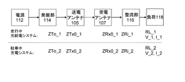
本発明の実施形態1における車両用充給電システムは、走行中の車両への充電、給電のうち少なくとも一方を行う走行中充給電システム、または駐車中の車両への充電、給電のうち少なくとも一方を行う駐車中充給電システムとして用いられる。なお、本明細書において、「充電」とは車両内に設けられた二次電池を充電し車両を駆動するための電力を蓄えることを指す。また、「給電」とは車載の駆動用電気モータなどの負荷に電力を供給することを指す。本実施形態の車両用充給電システムは、路面上または路面下に設けられた送電アンテナと、車両に設けられた受電アンテナとを備えている。送電アンテナと受電アンテナとが共振磁界結合することにより、無線で電力が伝送される。
(Embodiment 1)
The vehicle charging / feeding system according to the first exemplary embodiment of the present invention performs at least one of charging / feeding during running, charging / feeding during running, or charging / feeding during parking of the vehicle. It is used as a charging and feeding system during parking. In the present specification, “charging” refers to storing power for driving a vehicle by charging a secondary battery provided in the vehicle. Further, “power feeding” refers to supplying electric power to a load such as an in-vehicle driving electric motor. The vehicle charging / feeding system according to the present embodiment includes a power transmission antenna provided on the road surface or below the road surface, and a power receiving antenna provided on the vehicle. When the power transmission antenna and the power reception antenna are coupled to each other by a resonant magnetic field, power is transmitted wirelessly.
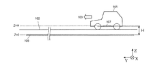
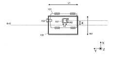
図1Aは、本実施形態における車両用充給電システムの上面透視模式図である。また、図1Bは、図1Aを側面から見たときの模式図である。説明のために、図1Aに示すXYZ座標を導入する。車両101の前後方向を±Y方向、車両101の進行方向103に向かって左右方向を±X方向、車両101の上下方向を±Z方向とする。特に説明がない場合、送電アンテナ105はXY平面に配置された矩形形状のインダクタを含むものとする。送電アンテナ105の重心を座標原点(X=Y=Z=0)とし、送電アンテナ105は移動しないものとする。また、受電アンテナ107もXY平面に平行に配置された矩形形状のインダクタを含むものとする。送電アンテナ105のX方向サイズをW1、Y方向サイズをL1とし、受電アンテナ107のX方向サイズをW2、Y方向サイズをL2とする。なお、本明細書においてアンテナのX方向またはY方向のサイズとは、各方向における長さを意味するものとする。また、図1Bに示すように、受電アンテナ107が配置された面のZ座標Hは、送電アンテナ105の配置面を基準とする受電アンテナ107の配置面の高さに相当する。
FIG. 1A is a schematic top perspective view of a vehicle charging / feeding system according to the present embodiment. FIG. 1B is a schematic diagram when FIG. 1A is viewed from the side. For the purpose of explanation, the XYZ coordinates shown in FIG. 1A are introduced. The longitudinal direction of the
後述するように、送電アンテナ105のX方向サイズW1およびY方向サイズL1は、それぞれ受電アンテナ107のX方向サイズW2およびY方向サイズL2よりも大きく設定される。したがって、送電アンテナ105の面積は受電アンテナ107の面積よりも大きく設定される。さらに、車両101のX方向の位置ずれに対して伝送特性の安定性を高めるために、送電アンテナ105と受電アンテナ107との対向距離Hは、後述するように、0.11×W1≦H≦0.26×W1の条件を満足するように設定される。図示される受電アンテナ107は、正方形に近い形状を有しているが、本発明はこの形状に限られるものではない。
As will be described later, the X direction size W1 and the Y direction size L1 of the
走行中充給電システム、駐車中充給電システムのいずれにおいても、送電アンテナ105はY方向に長い形状を有していることが好ましい。特に、走行中充給電システムにおいては、送電アンテナ105の面積は受電アンテナ107の面積よりも十分大きく設定されることが好ましい。受電アンテナ107の重心のXY座標は、車両101の重心のXY座標と同一に設定されることが好ましいが、必ずしも同一でなくとも本発明の効果は得られる。
In both the charging / feeding system during traveling and the charging / feeding system during parking, it is preferable that the
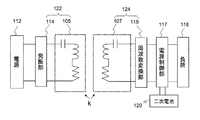
次に、本実施形態の車両用充給電システムの構成要素を説明する。図2Aは本実施形態の車両用充給電システムに用いられる回路構成の一部を示している。なお、図2Aに示す構成は本実施形態における一例であり、本発明はこの回路構成に限られない。例えば、各回路ブロック間にフィードバック制御の機能ブロックなどを必要に応じて追加してよい。 Next, the component of the vehicle charging / feeding system of this embodiment is demonstrated. FIG. 2A shows a part of a circuit configuration used in the vehicle charging / feeding system of the present embodiment. Note that the configuration shown in FIG. 2A is an example in this embodiment, and the present invention is not limited to this circuit configuration. For example, a functional block for feedback control may be added between the circuit blocks as necessary.
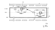
本実施形態の車両用充給電システムは、路面に設置された送電部122と車両101に設置された受電部124とを有している。送電部122は、電源112から出力されるエネルギ(電力)を受け取りRFエネルギに変換して出力する発振部114と、発振部114から出力されたRFエネルギから共振磁界を発生させる送電アンテナ105とを備えている。受電部124は、送電アンテナ105が発生した共振磁界と結合してRFエネルギを受け取る受電アンテナ107と、受電アンテナ107が受け取ったRFエネルギを直流エネルギに変換し出力する整流部116とを備えている。
The vehicle charging / feeding system of the present embodiment includes a
車両101は、電源制御部117、二次電池120および負荷118をさらに有している。二次電池120および負荷118は、整流部116が出力した直流エネルギによって充電され、または動作する。電源制御部117は、整流部116から負荷118または二次電池120へのエネルギ出力を制御する。電源制御部117はまた、二次電池120に蓄えられた電力を負荷118に供給するための制御も行う。
The
ここで、二次電池120は、どのような二次電池でもよい。例えばリチウムイオン電池、ニッケル水素電池などが利用可能である。負荷118は、電気モータとそれに接続される駆動回路とを含む。また、電気で動作する他の機器を含んでいても良い。なお、本実施形態の車両101は、電気モータを動力源とする車両であるが、本発明の車両用充給電システムは、内燃機関を動力源とする車両にも適用可能である。そのような車両に本発明の車両用充給電システムが用いられた場合、例えば無線電力伝送によって受け取った電力を利用して車載の照明などを動作させるガソリンエンジン車などが実現可能である。
Here, the
電源112には、商用電源(100V/200V)または大電力を供給可能に設計された給電装置などが用いられる。後段の発振部114への出力エネルギは直流成分に変換されていることが好ましい。発振部114には、D級、E級、F級などの、高効率且つ低歪な特性を実現できる増幅器を用いることができるし、ドハーティ増幅器を用いることもできる。歪成分を含む出力信号を発生するスイッチング素子の後段に、低域通過フィルタまたは帯域通過フィルタを配置することにより、高効率な正弦波を生成してもよい。整流部116には、例えば両波整流回路、ブリッジ整流回路、高倍圧整流回路等が適用可能である。また、同期整流方式を用いてもダイオード整流方式を用いても実現可能である。
As the
送電アンテナ105および受電アンテナ107は、少なくともインダクタ回路と容量回路とを含んでいる。各アンテナのインダクタ回路は、ループ形状またはスパイラル形状を有している。送電アンテナ105および受電アンテナ107は、所定の周波数fpで共振する共振回路となるよう設計されている。各アンテナの容量回路は、チップ容量素子などの集中定数回路素子で実現されていてもよいし、インダクタ配線に沿って分布的に生じる分布定数回路素子として少なくともその一部が実現されていてもよい。
The
なお、図2Aでは、送電アンテナ105および受電アンテナ107のいずれにおいても、インダクタ回路と容量回路とが直列接続されているが、必ずしもこの構成である必要はない。各アンテナにおいて、インダクタ回路および容量回路は直列接続されていてもよいし、並列接続されていてもよい。一方のアンテナでは直列接続され、他方のアンテナでは並列接続されていても本実施形態の効果に変わりはない。
In FIG. 2A, the inductor circuit and the capacitor circuit are connected in series in both the
また、送電アンテナ105および受電アンテナ107は、金属加工により単一配線から構成されていてもよいし、損失を低減するために複数本の撚り線からなるリッツ線を用いて構成されていてもよい。
In addition, the
受電アンテナ107は、好ましくは車両101の底面に設けられる。受電アンテナ107は、その下面と車両101の底面とが同一平面に位置するように車両内部に格納されていてもよいし、車両底面から下側に突き出た形状で設置されていてもよい。送電アンテナ105は、その表面と路面102とが同一平面に位置するように路面102に設置されていてもよいし、路面102よりも深い位置に埋設されていてもよい。送電アンテナ105は路面102から一定の深さに埋設されていてもよいし、送電アンテナ105の部分によって設置される位置が異なっていてもよい。
The
本実施形態では、送電アンテナ105および受電アンテナ107を構成する各インダクタ回路の形状は矩形としているが、本発明はこの形状に限定されない。両アンテナは楕円形状でもよいし、±Y方向に非対称な形状であってもよい。但し、X方向の磁界密度分布変動の吸収が、本発明の車両用充給電システムの動作原理である。車両への受電アンテナ107の配置幅が限定された場合、配置幅を最大限利用して、矩形形状とすることが好ましい。各アンテナが矩形形状を有する場合、その形状は厳密に矩形ではなく、角部分で一定以上の曲率を有することが好ましい。急激な配線角度の変化は、電流の集中および周辺空間の磁界密度の集中を招き、好ましくないからである。
In the present embodiment, the shape of each inductor circuit constituting the
次に、各回路ブロック間のインピーダンス整合について図2Bを参照しながら説明する。 Next, impedance matching between the circuit blocks will be described with reference to FIG. 2B.
図2Bは、本実施形態の車両用充給電システムの構成ブロック図と、各回路ブロックの入出力インピーダンスとを示している。ここで、図2Aに記載の構成要素のうち、電源制御部117と二次電池120の回路ブロックは省略している。ここで、送電アンテナ105と受電アンテナ107との間の電力伝送効率を最大化する送電アンテナ105の入力インピーダンスおよび受電アンテナ107の出力インピーダンスを、それぞれ送電アンテナ105の最適入力インピーダンスZTx0および受電アンテナ107の最適出力インピーダンスZTr0とする。
FIG. 2B shows a configuration block diagram of the vehicle charging / feeding system of the present embodiment and input / output impedances of each circuit block. Here, among the components shown in FIG. 2A, the circuit blocks of the
回路ブロック間のRFエネルギの多重反射を抑制し、総合発電効率を最適化するために、発振部114の出力インピーダンスZToと送電アンテナ105の最適入力インピーダンスZTx0とを一致させることが好ましい(整合条件1)。同様に、受電アンテナ107の最適出力インピーダンスZRx0と整流部116の入力インピーダンスZRiとを一致させることが好ましい(整合条件2)。さらに、入力インピーダンスZRiで整流部116が動作した時の出力インピーダンスZRoと負荷インピーダンスRLとを一致させることが好ましい(整合条件3)。以上の整合条件1〜3を同時に満足させることにより、伝送効率を最大化することができる。
In order to suppress multiple reflections of RF energy between circuit blocks and optimize the total power generation efficiency, it is preferable to match the output impedance ZTo of the
次に、車両への充給電時の無線電力伝送について説明する。 Next, wireless power transmission at the time of charging / feeding the vehicle will be described.
車両が移動し、送電アンテナ105が設置された領域上に受電アンテナ107が侵入すると、送電アンテナ105から受電アンテナ107への電力伝送が可能になる。車両101は、受電アンテナ107に伝送された電力から、車両101に搭載された二次電池120への充電、もしくは車両101の駆動回路等の負荷118への給電が可能である。負荷118への給電により、車両の電気モータや照明などを動作させることができる。
When the vehicle moves and the
本実施形態において、送電アンテナ105の面積は受電アンテナ107の面積よりも十分大きいため、送電アンテナ105を構成するインダクタと受電アンテナ107を構成するインダクタとの間の結合係数kは1を大幅に下回る。そのため、従来の電磁誘導方式を用いた場合、高効率の電力伝送は不可能である。本実施形態では、送電アンテナ105および受電アンテナ107は、共にほぼ同一の共振周波数で共振する共振器対を形成し、両アンテナのQ値は共に高く設計されている。そのため、インダクタ間の結合係数kが1を大幅に下回っても高い伝送効率の電力伝送が可能となる。
In this embodiment, since the area of the
次に、送電アンテナ105および受電アンテナ107の好ましいサイズと配置について説明する。
Next, preferred sizes and arrangements of the
車両用充給電システムには、高精度な位置補正を支援する自動走行(もしくは停車)システムを導入することなく、安定した伝送特性を維持することが求められる。そのためには、送電アンテナ105と受電アンテナ107との間に相対的な位置ずれが生じた際の伝送特性を把握し、対策を検討する必要がある。以下、Y方向(車両の前後方向)およびX方向(車両の横方向)の位置ずれに対して安定した伝送特性を維持できるアンテナのサイズと配置について説明する。
Vehicle charging and feeding systems are required to maintain stable transmission characteristics without introducing an automatic traveling (or stopping) system that supports highly accurate position correction. For this purpose, it is necessary to grasp the transmission characteristics when a relative positional deviation occurs between the
まず、Y方向の位置ずれについて説明する。送電アンテナ105と受電アンテナ107との間の相対的なY方向の位置ずれに対し、安定した伝送特性を確保することは重要である。なぜなら、走行中の車両101は、送電アンテナ105に対して充給電中も進行方向に向かって常に移動するし、駐車する車両も駐車スペースへ進入する際に、前後方向に移動するからである。Y方向の位置ずれに対してシステムが許容度を有するために、送電アンテナ105のY方向サイズL1は受電アンテナ107のY方向サイズL2よりも大きく設定される。すなわち、以下の式1を満たす。
(式1) L1>L2
First, the positional deviation in the Y direction will be described. It is important to ensure stable transmission characteristics against the relative displacement in the Y direction between the
(Formula 1) L1> L2
走行中充給電システムにおいては、送電アンテナ105のY方向サイズL1は好ましくは車両101のY方向サイズよりも大きい値に設定される。L1は、例えば数メートルから数百メートルに設定されることが好ましい。このように、L1をL2よりも大きくすることにより、送電アンテナ105の上をY方向に移動する車両101に対して安定した充給電特性を維持することが可能となる。
In the traveling charging / feeding system, the Y-direction size L1 of the
また、駐車中充給電システムでは、車両101は、駐車スペースに前進しながら、または後進しながら侵入する。運転者が車両101を停止させるときに、送電アンテナ105と受電アンテナ107とが対向する厳密な車両101の位置を意識させないためには、受電アンテナ107の車両101への搭載位置(Y座標)を車両のY座標の中心付近に設定することが好ましい。また、車両設計の自由度を向上させるため、送電アンテナ105のY方向サイズL1を車両101のY方向サイズとほぼ等しい長さに設定することが好ましい。ここで「ほぼ等しい」とは、車両101のY方向サイズに対する送電アンテナ105のY方向サイズL1の割合が20%〜300%の範囲内にあることを意味するものとする。図3は、以上の条件を満足する駐車中充給電システムの上面透視模式図である。この構成により、車両前方部底面、車両後方部底面のいずれに受電アンテナ107が配置されても電力伝送が可能となる。
In the charging / power-supply system during parking, the
次に、X方向の位置ずれについて説明する。本発明の車両用充給電システムでは、送電アンテナ105と受電アンテナ107との間の相対的なX方向の位置ずれに対しても安定した伝送特性を確保する必要がある。なぜなら、走行中の車両101は、充給電中もX方向にずれる可能性があるし、駐車する車両も駐車スペースに侵入するたびにX方向がずれることが一般的であるからである。
Next, the positional deviation in the X direction will be described. In the charging / feeding system for a vehicle according to the present invention, it is necessary to ensure stable transmission characteristics even with respect to a relative displacement in the X direction between the
走行中または駐車中の、送電アンテナ105に対する車両101のX方向の相対的な位置ずれに対してシステムが許容性を有するために、送電アンテナ105の幅W1、は受電アンテナ107の幅W2より広く設定される。すなわち、以下の式2を満たす。
(式2) W1>W2
The width W1 of the
(Formula 2) W1> W2
また、受電アンテナ107の車両101への搭載位置(X座標)は、車両のX座標の中心付近に設定されることが好ましい。
Further, the mounting position (X coordinate) of the
図4は、以上の条件を満たす走行中充給電システムにおいて、車両101が走行中に状態0から状態1へとX方向にずれている例を示している。図示される状態0は、車両101が走行レーンの中央を走行している状態(X=0)である。また、状態1は、車両101が走行レーンの右端に位置し、受電アンテナ107の全面積が辛うじて送電アンテナ105と対向している状態(X=X0)である。X0は以下の式3で表される。
(式3) X0=(W1−W2)/2
FIG. 4 shows an example in which the
(Formula 3) X0 = (W1-W2) / 2
したがって、以下の式4の範囲内で車両が移動しても、受電アンテナ107の全面積が送電アンテナ105と対向するため、高効率のエネルギ伝送が可能となる。
(式4) −X0≦X≦X0
Therefore, even if the vehicle moves within the range of the following expression 4, since the entire area of the
(Formula 4) -X0 ≦ X ≦ X0
しかしながら、送電アンテナ105の外径で囲まれた領域および送電アンテナ105の外部の領域の磁界密度の空間分布がX座標に依存していることから、式4の範囲内の位置ずれに対して安定した電力伝送特性を維持することは困難である。すなわち、状態0における送電アンテナの最適入力インピーダンスZTx0は、状態1における送電アンテナ105の最適入力インピーダンスZTx1と異なる。同様に、状態0における受電アンテナ107の最適出力インピーダンスZRx0は、状態1における受電アンテナ107の最適出力インピーダンスZRx1と異なる。
However, since the spatial distribution of the magnetic field density in the region surrounded by the outer diameter of the
ここで、ZTx0に対するZTx1の変動比率FTx、およびZRx0に対するZRx1の変動比率FRxを、それぞれ以下の式5、6で定義する。
(式5) FTx=ZTx1/ZTx0
(式6) FRx=ZRx1/ZRx0
Here, the fluctuation ratio FTx of ZTx1 with respect to ZTx0 and the fluctuation ratio FRx of ZRx1 with respect to ZRx0 are defined by the following equations 5 and 6, respectively.
(Formula 5) FTx = ZTx1 / ZTx0
(Formula 6) FRx = ZRx1 / ZRx0
すると、式5、6で表されるFTx、FRxがそれぞれ1から逸脱するほど、X方向の位置ずれに対して伝送特性が不安定になる。インピーダンスの変動は、発振部114と送電アンテナ105との間および受電アンテナ107と整流部116との間のエネルギの反射、不要な電力損失や回路の温度上昇、漏洩ノイズを引き起こす。そのため、受電エネルギの電圧が設計値とずれる可能性が生じる。その結果、電圧安定のために電源制御部にレギュレータやDC−DCコンバータなどの電圧制御機能を導入せざるを得なくなり、エネルギ利用効率の低下を招く。
Then, as FTx and FRx expressed by Expressions 5 and 6 deviate from 1, respectively, transmission characteristics become unstable with respect to the positional deviation in the X direction. The fluctuation in impedance causes energy reflection between the
本願発明者は、上記の課題を新たに発見し、検討した結果、上記課題によってもたらされる電力伝送特性の不安定性を緩和する条件を導出した。すなわち、送電アンテナ105と受電アンテナ107との対向距離Hは、以下の式7の条件を満足するように設定される。
(式7) 0.11×W1≦H≦0.26×W1
The inventor of the present application newly discovered and studied the above problems, and as a result, derived conditions for alleviating the instability of power transmission characteristics caused by the above problems. That is, the facing distance H between the
(Formula 7) 0.11 × W1 ≦ H ≦ 0.26 × W1
式7の条件を満足させることにより、車両101のX方向の位置ずれに対して、電力伝送特性の不安定性を緩和させることができる。具体的には、図4に示される状態0から状態1へ車両が充給電されながら移動する際に、送電アンテナ105の最適入力インピーダンスと受電アンテナ107の最適出力インピーダンスとの間の変動幅を約21%以内に抑えることが可能となる。その結果、負荷118の電圧変動幅を約10%以内に抑えることができる(実施例1参照)。
By satisfying the condition of
より好ましくは、以下の式8の条件を満たすように各アンテナは構成される。
(式8) 0.12×W1≦H≦0.22×W1
More preferably, each antenna is configured so as to satisfy the condition of Equation 8 below.
(Formula 8) 0.12 × W1 ≦ H ≦ 0.22 × W1
式8の条件を満足させることにより、送電アンテナ105の最適入力インピーダンスと受電アンテナ107の最適出力インピーダンスとの間の変動幅を約10.25%以内に抑えることが可能となる。その結果、負荷118の電圧変動幅を約5%以内に抑えることができる。
By satisfying the condition of Expression 8, it is possible to suppress the fluctuation range between the optimum input impedance of the
さらに好ましくは、以下の式9の条件を満たすように各アンテナは構成される。
(式9) 0.15×W1≦H≦0.19×W1
More preferably, each antenna is configured so as to satisfy the condition of Equation 9 below.
(Formula 9) 0.15 × W1 ≦ H ≦ 0.19 × W1
式9の条件を満足させることにより、送電アンテナ105の最適入力インピーダンスと受電アンテナ107の最適出力インピーダンスとの間の変動幅を約6.05%以内に抑えることが可能となる。その結果、負荷118の電圧変動幅を約3%以内に抑えることができる。
By satisfying the condition of Expression 9, it is possible to suppress the fluctuation range between the optimum input impedance of the
上記の式7〜9で示される条件を満足することにより、車両のX方向の位置ずれに対する伝送特性の安定性を高めることができる。
By satisfying the conditions expressed by the
さらに、駐車中充給電システムにおいては、送電アンテナ105のX方向サイズは車両幅程度に設計されることが好ましい。また、走行中充給電システムにおいては、送電アンテナ105のX方向サイズは、車両走行エリアの幅程度の拡がりをもって設計されることが好ましい。送電アンテナ105の幅が車両走行エリアの幅よりも大きい構成では、複数レーンを一台の送電アンテナでカバーすることになる。その場合、通行車両数の変動による負荷の変動を招く可能性があるため、好ましくない。
Further, in the parking charging / feeding system, the size of the
なお、走行中充給電システムでは、車両は走行レーンの中心軸付近を走行することが多い。そのため、送電アンテナ105は、その中心部が走行レーンの中央に位置するように配置されることが好ましい。
In the traveling charging / supply system, the vehicle often travels near the central axis of the traveling lane. Therefore, it is preferable that the
以上の条件を満たすようにアンテナのサイズおよび配置を決定することにより、本実施形態の車両用充給電システムでは、車両101のX方向およびY方向の位置ずれに対して、伝送特性を安定化させることが可能となる。
By determining the size and arrangement of the antenna so as to satisfy the above conditions, the vehicle charging / feeding system of the present embodiment stabilizes the transmission characteristics against the positional deviation of the
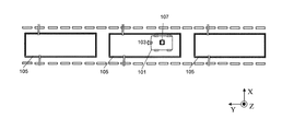
以上説明した車両用充給電システムは、一つの送電アンテナ105を備えていたが、送電アンテナ105を複数備えていてもよい。例えば、車両進行方向103に沿って複数の送電アンテナ105からなる送電アンテナ群を路面に配置することができる。図5はそのような構成を示す上面透視模式図である。このような構成は、特に走行中充給電システムにおいて有用である。車両101の走行中、車両101の位置に対向した送電アンテナ105が車両101内の受電アンテナ107に対し連続してエネルギ伝送を行うことにより、走行中の車両101への継続的な充給電が可能となる。
The vehicle charging / feeding system described above includes one
次に、走行中充給電システムと駐車中充給電システムとの整合性について説明する。 Next, the consistency between the charging / feeding system during traveling and the charging / feeding system during parking will be described.
本実施形態の車両用充給電システムは、走行中充給電システムに用いられる送電アンテナ105と駐車中充給電システムに用いられる送電アンテナ105とを同時に含んでいてもよい。さらに、走行中充給電システムの一部を構成する受電部124(受電アンテナ107と整流部116とを含む)は、同時に駐車中充給電システムの受電部124を構成するよう設計することが可能である。言い換えれば、走行中にも駐車中にも単一の機器で充給電が可能な機能を車両に付与することができる。
The vehicular charging / feeding system of the present embodiment may include a
図6は、両システムにおける、各回路ブロックでのインピーダンスおよび負荷での電流・電圧を示している。なお、図2Aに記載の構成要素のうち、電源制御部と二次電池の回路ブロックは省略している。走行中充給電システムと駐車中充給電システムとでは、送電アンテナ105と受電アンテナ107との間の結合係数kは異なる。そのため、図示される各パラメータ値は、走行中充給電システムと駐車中充給電システムとでは必ずしも同一の値とはならない。例えば、走行中充給電システムにおける受電アンテナ107の最適出力インピーダンスZRx0_1は、駐車中充給電システムにおける受電アンテナ107の最適出力インピーダンスZRx0_2と異なる値であってもよい(以下、「_1」は走行中充給電システム、「_2」は駐車中充給電システムでのパラメータであることを示す)。同様に、発振部114の最適出力インピーダンスZTo_1とZTo_2、送電アンテナ105の最適入力インピーダンスZTx0_1とZTx0_2、整流部116の最適入力インピーダンスZRi_1とZRi_2、負荷118の最適入力インピーダンスRL_1とRL_2とは、それぞれ異なる値をとってよい。整流部116は、ZRi_1とZRi_2の両方の入力インピーダンスに対して高効率で動作することが好ましい。
FIG. 6 shows the impedance in each circuit block and the current / voltage at the load in both systems. In addition, the circuit block of a power supply control part and a secondary battery is abbreviate | omitted among the components described in FIG. 2A. The coupling coefficient k between the
また、負荷118(充電器等)への入力電圧(整流部116からの出力電圧)(V_1とV_2)は、負荷118の入力電圧の許容範囲内に収まるよう設計することが好ましい。さらに好ましくは、V_1とV_2とはほぼ等しい値となるように設計される。ここで「ほぼ等しい」とは、V_1/V_2の値が0.8〜1.2の範囲内にあることを意味するものとする。V1/V2の値が0.8〜1.2の範囲内である場合、レギュレータやDC−DCコンバータなどの電圧制御機能の動作特性が良好な条件範囲で使用できるため、エネルギ利用効率を高く維持することができる。さらに好ましくは、V1/V2の値は0.9〜1.1の範囲内に設計される。V1/V2の値が0.9〜1.1の場合は、対電圧変動特性に優れた電池を用いる場合において、上記電圧制御機能を排除することが可能となる。また、V1/V2の値が0.95〜1.05の範囲内にある場合は、一般的な電池を用いる場合においても、上記電圧制御機能を排除することが可能となる。さらに、V1/V2の値が0.97〜1.03の範囲内にある場合は、電池の耐電圧変動特性を向上させることなく容量やコストなどの特性仕様を追求した電池を、電圧制御機能抜きで用いることが可能となり、より優位な効果が生じる。また、上記説明では電池を例に挙げて説明したが、動力部などの負荷についても、同様のことが言える。
In addition, it is preferable that the input voltage (output voltage from the rectifying unit 116) (V_1 and V_2) to the load 118 (charger or the like) is designed to be within an allowable range of the input voltage of the
なお、本実施形態では、負荷118に含まれる電気モータは、整流部116から出力される直流(DC)エネルギによって動作する直流モータであるが、直流モータではなく交流モータを用いることも可能である。交流モータを用いる場合、例えば以下の2つの構成が可能である。第1の構成は、図2Aにおける電源制御部117が直流(DC)から交流(AC)への変換を行い、当該ACエネルギを交流モータに送出する構成である。この構成においては、交流モータにはACエネルギを供給するが、二次電池120にはDCエネルギを供給するように電源制御部117は構成される。第2の構成は、整流部116の代わりに周波数変換部119を用いる構成である。周波数変換部119は、受電アンテナ107が受け取ったRFエネルギをそれよりも低い周波数の交流(AC)エネルギに変換する回路である。この第2の構成では、周波数変換部119から出力される交流エネルギが交流モータに供給される。図7は、第2の構成における回路ブロックの一例を示している。図7に示す構成では、周波数変換部119から出力されるACエネルギが電源制御部117を介して交流モータ(負荷118)に供給される。一方、二次電池120を充電する際には、電源制御部117は交流(AC)から直流(DC)への変換を行い、DCエネルギを二次電池120に送出する。周波数変換部119を用いる場合においては、周波数変換部119の入出力インピーダンスを負荷や他の回路ブロックのインピーダンスに整合させることが好ましい。
In the present embodiment, the electric motor included in the
また、図7に示す周波数変換部119を用いる場合でも、上記の実施形態と同様、受電アンテナ107は、複数の異なる送電アンテナの各々との間で非接触の電力伝送を行うことが可能である。ここで、1つの送電アンテナと受電アンテナ107との間の結合係数は、他の送電アンテナと受電アンテナ107との間の結合係数と異なっていてもよい。これらの結合係数が異なる場合であっても、負荷118や二次電池120の入力電圧がほぼ等しくなるようにシステムが設計されていることが好ましい。
In addition, even when the
以下、本実施形態の効果を従来技術と比較しながら説明する。 Hereinafter, the effects of the present embodiment will be described in comparison with the prior art.
本実施形態の車両用充給電では、送電アンテナの面積は受電アンテナの面積よりも十分大きい。このような構成において車両の位置ずれへの対策を講じた技術は、従来文献には開示されていない。本実施形態の車両用充給電システムによれば、車両のX方向、Y方向への位置ずれに対する伝送特性の安定性を共に向上させることができる。 In the vehicle charging / feeding of this embodiment, the area of the power transmission antenna is sufficiently larger than the area of the power reception antenna. A technique for taking measures against a positional deviation of the vehicle in such a configuration has not been disclosed in the literature. According to the vehicle charging / feeding system of the present embodiment, it is possible to improve both the stability of the transmission characteristics against the positional deviation of the vehicle in the X direction and the Y direction.
特許文献2では、駐車中の車両に対する充給電に際して、車両や路面に複数のアンテナを配置することによってX方向の位置ずれに対応している。しかしながら、複数のアンテナの設置は、低コスト化や小型化の障害になるため、好ましくない。さらに、伝送ブロックにアンテナを切り替えるスイッチを新たに導入しなければならないため、スイッチの挿入損失による伝送効率の低下が懸念される。特許文献2にはそのような伝送効率の低下を回避する構成が開示されていない。
In
本発明では、送電アンテナから受電アンテナへのエネルギ伝送は、受電アンテナが送電アンテナ上の空間に位置した場合に限定される。これは、両アンテナを構成するインダクタ間の結合係数が極端に低下すると高効率伝送が困難になるからである。 In the present invention, energy transmission from the power transmission antenna to the power reception antenna is limited to a case where the power reception antenna is located in a space on the power transmission antenna. This is because high-efficiency transmission becomes difficult when the coupling coefficient between the inductors constituting both antennas is extremely reduced.
一方、電磁誘導方式による特許文献3の構成では、車両の左右方向の位置ずれを改善すべく導入した構成の結果、効率の一層の低下を招くことになってしまう。特許文献3の道路側送電装置の構成では、本発明の送電アンテナの半分の幅のアンテナエレメントが配置されることになる。また、車両側も同様に、限られた車両幅に対して左右2つのアンテナエレメントが配置される。送電側、受電側それぞれ2つのアンテナエレメントにより、4つの組み合わせが考えられる。特許文献3の手法は、いずれの組み合わせでも強い結合となる条件下で、かつ各組み合わせ間の伝送に対し振幅位相制御を個別に行うことによって初めて高効率且つ安定した伝送を提供できる。しかし、実際には4つの結合のうち、少なくとも2つの結合はインダクタ間の相対距離が必ず遠くなる組み合わせにならざるを得ない。特に、車両の横方向の位置ずれが大きくなるほど、全結合が良好な伝送効率を達成することは困難になる。また、各伝送経路の制御を行う制御素子や切替素子の挿入損分だけ伝送効率が低下する問題を回避する手段が開示されていない。 On the other hand, in the configuration of Patent Document 3 based on the electromagnetic induction method, the efficiency is further reduced as a result of the configuration introduced to improve the lateral displacement of the vehicle. In the configuration of the roadside power transmission device of Patent Document 3, an antenna element having a width half that of the power transmission antenna of the present invention is arranged. Similarly, on the vehicle side, two left and right antenna elements are arranged for a limited vehicle width. Four combinations are conceivable with two antenna elements on each of the power transmission side and the power reception side. The method of Patent Document 3 can provide highly efficient and stable transmission only under the condition that any combination is strong coupling and by performing amplitude phase control individually for the transmission between each combination. However, in practice, at least two of the four couplings must be a combination in which the relative distance between the inductors is necessarily increased. In particular, the greater the lateral displacement of the vehicle, the more difficult it is to achieve good transmission efficiency for all connections. Also, there is no disclosure of means for avoiding the problem that the transmission efficiency is reduced by the insertion loss of the control elements or switching elements that control each transmission path.
また、従来技術には、進行波である電磁波を用いて送電アンテナから受電アンテナへエネルギ伝送する車両用充給電システムもある(例えば、特開2002−152996号公報)。しかし、この従来技術は、共振磁界結合を用いる本発明の車両用充給電システムとは原理が異なる。この従来技術においては、受電アンテナの形状がW2>L2であっても、本発明の受電アンテナ構成においてもたらされる、左右方向の車両位置ずれに対する許容度向上の効果は見出せない。むしろ、進行波を放射するアンテナにおいて左右方向に開口幅を拡大することは、左右方向の放射半値幅を低減し、位置ずれに対する許容度が低下すると考えられる。よって、本発明の効果は共振磁界結合方式において、送電アンテナのサイズが受電アンテナのサイズに対して大きい場合においてのみ発現する特有の効果である。 In addition, there is a vehicle charging / feeding system that transmits energy from a power transmitting antenna to a power receiving antenna using electromagnetic waves that are traveling waves (for example, JP 2002-152996 A). However, this prior art is different in principle from the vehicle charging / feeding system of the present invention using the resonant magnetic field coupling. In this prior art, even if the shape of the power receiving antenna is W2> L2, it is not possible to find the effect of improving the tolerance with respect to the vehicle position shift in the left-right direction, which is brought about in the power receiving antenna configuration of the present invention. Rather, enlarging the aperture width in the left-right direction in an antenna that radiates traveling waves is considered to reduce the radiation half-width in the left-right direction and reduce the tolerance for displacement. Therefore, the effect of the present invention is a unique effect that appears only when the size of the power transmitting antenna is larger than the size of the power receiving antenna in the resonant magnetic field coupling method.
以下、本発明の実施例1を説明する。 Embodiment 1 of the present invention will be described below.
本発明の有利な効果を実証するべく、図1A、図1Bに示す構成に基づき、車両用充給電システムの実施例1a、1bによる解析を行った。実施例1aでは、W1=250cm、L1=1000cm、W2=L2=65cmとした。実施例1bでは、W1およびL1は実施例1aと同一の値とし、W2=43.3cm、L2=86.7cmとした。送電アンテナおよび受電アンテナの共振周波数はともに500kHzとなるよう設計した。伝送損失を低減させるため、送電アンテナおよび受電アンテナの配線としてリッツ線を採用した。 In order to verify the advantageous effects of the present invention, the vehicle charging / feeding system according to Examples 1a and 1b was analyzed based on the configuration shown in FIGS. 1A and 1B. In Example 1a, W1 = 250 cm, L1 = 1000 cm, and W2 = L2 = 65 cm. In Example 1b, W1 and L1 were set to the same values as in Example 1a, and W2 = 43.3 cm and L2 = 86.7 cm. The resonance frequency of the power transmission antenna and the power reception antenna was designed to be 500 kHz. In order to reduce transmission loss, litz wire was adopted as the wiring of the power transmission antenna and power reception antenna.
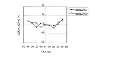
送電アンテナおよび受電アンテナの入出力端子をネットワークアナライザに接続し、小信号入力条件で通過/反射特性を測定し、アンテナ間の伝送効率を最大化する最適インピーダンス値を測定した。図4に示す状態1の配置(X=Xo)で測定を行った後、図4に示す状態0の配置(X=0)に車両位置を移動させて測定を行った。2回の測定結果から、車両の進行方向に向かって左右方向の位置ずれに対する伝送特性の安定度を見積もった。以上の測定を、Y=0の条件で、複数通りのHの値に対して行うことにより、インピーダンス変動特性のH依存性を評価した。
The input / output terminals of the power transmission antenna and the power reception antenna were connected to a network analyzer, the pass / reflection characteristics were measured under small signal input conditions, and the optimum impedance value that maximized the transmission efficiency between the antennas was measured. After the measurement was performed in the state 1 arrangement (X = Xo) shown in FIG. 4, the measurement was performed by moving the vehicle position to the
表1は、実施例1a、1bにおける評価の結果を示している。また、図8、図9はそれぞれ、実施例1a、1bにおけるインピーダンス変動特性のH依存性を示している。ここで、ΔFTxおよびΔFRxは、それぞれ送電アンテナおよび受電アンテナのインピーダンス変動を表している。ΔFTxおよびΔFRxの値がゼロに近いほど、X方向の位置ずれに対するシステム耐性が優位である。 Table 1 shows the results of evaluation in Examples 1a and 1b. 8 and 9 show the H dependence of the impedance fluctuation characteristics in Examples 1a and 1b, respectively. Here, ΔFTx and ΔFRx represent impedance fluctuations of the power transmitting antenna and the power receiving antenna, respectively. The closer the values of ΔFTx and ΔFRx are to zero, the more superior the system resistance to displacement in the X direction.

各実施例において、インピーダンス整合を完全に行った場合の最大伝送効率は、状態1、状態0で大きな変化はなかった。よって、状態1において伝送電力を最大化した場合の受電電圧VRi_1は状態0での受電電圧VRi_0およびFRxを用いて以下の式10で表される。
(式10)VRi_1=VRi_0×(FRx)^0.5
In each example, the maximum transmission efficiency when impedance matching was completely performed did not change greatly between state 1 and
(Formula 10) VRi_1 = VRi_0 × (FRx) ^ 0.5
式10より、負荷または二次電池の電圧変動幅が10%まで許容される場合、FRxの変動幅は21%までが許容されることになる。表1より、H/W1の値が式7の条件を満たす範囲内であれば、電圧変動幅を約10%以内にできることがわかる。また、負荷または二次電池の電圧変動幅が5%まで許容される場合、FRxの変動幅は10.25%までが許容されることになる。この場合、表1より、H/W1の値が式8の条件を満たす範囲内であれば、電圧変動幅を約5%以内にできることがわかる。また、負荷または二次電池の電圧変動幅が3%まで許容される場合、FRxの変動幅は6.09%までが許容されることになる。この場合、表1より、H/W1の値が式9の条件を満たす範囲内であれば、電圧変動幅を約3%以内にできることがわかる。すなわち、式7〜9に相当する各Hの範囲において、本発明の車両用充給電システムは安定した伝送特性が得られることが証明された。また、式7〜9に相当する各Hの範囲において、ZTx値の極端な変動がないため、送電アンテナと送信機ブロック間での信号反射を低減できる。そのため、発振部ブロックの回路で用いるデバイスの耐圧特性仕様を過剰に見積もる必要がない。
From
次に、実施例1aの構成でH=0.1757×W1とし、X=0及びX=X0の2状態を保ったまま、車両をY軸方向へ移動させた。図10は、このときのインピーダンスZTx1およびZTx0のY依存性を示している。同様に、図11は、インピーダンスZRx1およびZRx0のY依存性を示している。図10、11において、値は全てY=0での値を基準に規格化した。図10、図11より、Y軸方向の移動に対するインピーダンス変動は、送電側および受電側のいずれの端子においても6%以内に収まっている。したがって、車両進行方向の移動に対しても本発明の車両充給電システムが良好な伝送特性を維持できることが証明された。 Next, H = 0.1757 × W1 in the configuration of Example 1a, and the vehicle was moved in the Y-axis direction while maintaining the two states of X = 0 and X = X0. FIG. 10 shows the Y dependency of the impedances ZTx1 and ZTx0 at this time. Similarly, FIG. 11 shows the Y dependence of the impedances ZRx1 and ZRx0. 10 and 11, all values are normalized based on the value at Y = 0. From FIG. 10 and FIG. 11, the impedance fluctuation | variation with respect to the movement of a Y-axis direction is settled in less than 6% in any terminal of a power transmission side and a power receiving side. Therefore, it has been proved that the vehicle charging / feeding system of the present invention can maintain good transmission characteristics with respect to movement in the vehicle traveling direction.
さらに、電源及び発振部を送電アンテナに接続し、整流部および負荷を受電アンテナに接続し、各接続点でインピーダンス整合条件を満足させた。このような構成において、送電アンテナから車両内の二次電池への充電を行うことができた。 Furthermore, the power source and the oscillation unit were connected to the power transmission antenna, the rectification unit and the load were connected to the power reception antenna, and the impedance matching condition was satisfied at each connection point. In such a configuration, the secondary battery in the vehicle can be charged from the power transmission antenna.
また、L1を250cmに減じた車両充給電システムのインピーダンス変動特性も同様に測定した。この場合も、上記と同様に式7〜9の条件で本発明の効果が得られた。
Moreover, the impedance fluctuation characteristic of the vehicle charging / discharging system which reduced L1 to 250 cm was measured similarly. Also in this case, the effects of the present invention were obtained under the conditions of
本発明にかかる車両用充給電システムは、電気自動車への走行中充給電システム、駐車中充給電システムとして利用できる。本発明は、電気自動車に限らず、電動バイク、移動ロボット等のあらゆる車両の充給電に応用できる。 INDUSTRIAL APPLICABILITY The vehicle charging / feeding system according to the present invention can be used as a charging / feeding system for traveling to an electric vehicle and a charging / feeding system during parking. The present invention is not limited to an electric vehicle and can be applied to charging and feeding of all vehicles such as an electric motorcycle and a mobile robot.
101 車両
102 路面
103 車両進行方向
105 送電アンテナ
107 受電アンテナ
112 電源
114 発振部
116 整流部
117 電源制御部
118 負荷
119 周波数変換部
120 二次電池
122 送電部
124 受電部
DESCRIPTION OF
Claims (21)
前記送電アンテナおよび前記受電アンテナは、共振磁界によって互いに結合する共振器対であり、
車両進行方向をY方向、前記車両進行方向に垂直な方向をX方向とするとき、
前記送電アンテナのY方向の長さおよびX方向の長さは、それぞれ、前記受電アンテナのY方向の長さおよびX方向の長さよりも大きく、
前記送電アンテナのX方向の長さをW1、前記送電アンテナと前記受電アンテナの対向距離をHとするとき、
0.11×W1≦H≦0.26×W1
を満足し、
前記送電アンテナと前記受電アンテナとが対向するときに前記送電アンテナから前記受電アンテナに非接触で電力を供給する車両用充給電システム。 A vehicle charging / feeding system including at least one power transmission antenna provided on or below a road surface and a power reception antenna provided on at least one vehicle,
The power transmitting antenna and the power receiving antenna are a resonator pair coupled to each other by a resonant magnetic field,
When the vehicle traveling direction is the Y direction and the direction perpendicular to the vehicle traveling direction is the X direction,
The length of the power transmission antenna in the Y direction and the length of the X direction are larger than the length of the power reception antenna in the Y direction and the length of the X direction, respectively.
When the length in the X direction of the power transmission antenna is W1, and the facing distance between the power transmission antenna and the power reception antenna is H,
0.11 × W1 ≦ H ≦ 0.26 × W1
Satisfied,
A vehicle charging / feeding system that supplies power from the power transmitting antenna to the power receiving antenna in a contactless manner when the power transmitting antenna and the power receiving antenna face each other.
を満足する請求項1に記載の車両用充給電システム。 0.12 × W1 ≦ H ≦ 0.22 × W1
The vehicle charging / feeding system according to claim 1, wherein:
を満足する請求項2に記載の車両用充給電システム。 0.15 × W1 ≦ H ≦ 0.19 × W1
The vehicle charging / feeding system according to claim 2, wherein:
前記車両は、前記受電アンテナが前記送電アンテナから受けとったRFエネルギを直流エネルギまたは前記RFエネルギよりも周波数の低い交流エネルギに変換して出力する電力変換部を有する請求項1から3のいずれかに記載の車両用充給電システム。 An oscillation unit that converts energy received from a power source into RF energy and sends the energy to the power transmission antenna;
4. The vehicle according to claim 1, further comprising: a power converter configured to convert the RF energy received by the power receiving antenna from the power transmitting antenna into direct current energy or alternating current energy having a frequency lower than the RF energy and output the same. The vehicle charging / feeding system according to claim.
前記第1の送電アンテナと前記受電アンテナとの間の結合係数は、前記第2の送電アンテナと前記受電アンテナとの間の結合係数と異なっており、
前記第1の送電アンテナと前記受電アンテナとが電力伝送を行うときの前記負荷の入力電圧は、前記第2の送電アンテナと前記受電アンテナとが電力伝送を行うときの前記負荷の入力電圧とほぼ等しくなるように設計されている、請求項7または8に記載の車両用充給電システム。 The at least one power transmission antenna includes a first power transmission antenna and a second power transmission antenna;
The coupling coefficient between the first power transmitting antenna and the power receiving antenna is different from the coupling coefficient between the second power transmitting antenna and the power receiving antenna;
The input voltage of the load when the first power transmitting antenna and the power receiving antenna perform power transmission is approximately the same as the input voltage of the load when the second power transmitting antenna and the power receiving antenna perform power transmission. The charging / feeding system for a vehicle according to claim 7 or 8, which is designed to be equal.
前記受電アンテナが前記送電アンテナから受け取ったエネルギによって前記二次電池を充電する請求項1から9のいずれかに記載の車両用充給電システム。 The vehicle has a secondary battery,
The vehicle charging / feeding system according to claim 1, wherein the power receiving antenna charges the secondary battery with energy received from the power transmitting antenna.
前記車両の移動に伴って前記受電アンテナが前記複数の送電アンテナの各々と対向するとき、前記受電アンテナに対向する送電アンテナから前記受電アンテナに順次電力伝送を行う請求項1から15のいずれかに記載の車両用充給電システム。 The at least one power transmission antenna includes a plurality of power transmission antennas arranged along the Y direction,
The power transmission from the power transmission antenna facing the power reception antenna to the power reception antenna is sequentially performed when the power reception antenna faces each of the plurality of power transmission antennas as the vehicle moves. The vehicle charging / feeding system according to claim.
前記受電アンテナと、
前記受電アンテナが前記送電アンテナから受け取ったエネルギによって動作する負荷と、
を有する車両。 It is a vehicle used for the charging / feeding system for vehicles according to any one of claims 1 to 16,
The power receiving antenna;
A load operated by the energy received by the power receiving antenna from the power transmitting antenna;
Vehicle with.
前記受電アンテナが前記送電アンテナから受け取ったRFエネルギを直流エネルギまたは前記RFエネルギよりも周波数の低い交流エネルギに変換して出力する電力変換部とを備える受電システム。 A power receiving antenna used for the vehicle charging / feeding system according to any one of claims 1 to 16,
A power receiving system comprising: a power conversion unit configured to convert the RF energy received from the power transmission antenna by the power receiving antenna into direct current energy or alternating current energy having a frequency lower than the RF energy.
Applications Claiming Priority (2)
| Application Number | Priority Date | Filing Date | Title |
|---|---|---|---|
| US26093709P | 2009-11-13 | 2009-11-13 | |
| US61/260,937 | 2009-11-13 |
Related Child Applications (1)
| Application Number | Title | Priority Date | Filing Date |
|---|---|---|---|
| JP2016015340A Division JP6179826B2 (en) | 2009-11-13 | 2016-01-29 | Charging and feeding system for vehicles |
Publications (2)
| Publication Number | Publication Date |
|---|---|
| JP2011109902A true JP2011109902A (en) | 2011-06-02 |
| JP5909714B2 JP5909714B2 (en) | 2016-04-27 |
Family
ID=43558293
Family Applications (2)
| Application Number | Title | Priority Date | Filing Date |
|---|---|---|---|
| JP2010252236A Active JP5909714B2 (en) | 2009-11-13 | 2010-11-10 | Charging and feeding system for vehicles |
| JP2016015340A Active JP6179826B2 (en) | 2009-11-13 | 2016-01-29 | Charging and feeding system for vehicles |
Family Applications After (1)
| Application Number | Title | Priority Date | Filing Date |
|---|---|---|---|
| JP2016015340A Active JP6179826B2 (en) | 2009-11-13 | 2016-01-29 | Charging and feeding system for vehicles |
Country Status (5)
| Country | Link |
|---|---|
| US (1) | US8552685B2 (en) |
| EP (1) | EP2465179B1 (en) |
| JP (2) | JP5909714B2 (en) |
| CN (2) | CN105305657B (en) |
| WO (1) | WO2011059108A1 (en) |
Cited By (1)
| Publication number | Priority date | Publication date | Assignee | Title |
|---|---|---|---|---|
| JP2013223262A (en) * | 2012-04-12 | 2013-10-28 | Hitachi Cable Ltd | Resonance type non-contact feeding system |
Families Citing this family (203)
| Publication number | Priority date | Publication date | Assignee | Title |
|---|---|---|---|---|
| US20160043571A1 (en) * | 2008-09-27 | 2016-02-11 | Witricity Corporation | Resonator enclosure |
| GB2476497A (en) * | 2009-12-23 | 2011-06-29 | Bombardier Transp Gmbh | Transferring electromagnetic energy to a vehicle |
| US20110302078A1 (en) | 2010-06-02 | 2011-12-08 | Bryan Marc Failing | Managing an energy transfer between a vehicle and an energy transfer system |
| US9143010B2 (en) * | 2010-12-28 | 2015-09-22 | Tdk Corporation | Wireless power transmission system for selectively powering one or more of a plurality of receivers |
| JP5338851B2 (en) * | 2011-05-23 | 2013-11-13 | 株式会社デンソー | Power transmission / reception system for vehicles |
| CN103828188B (en) * | 2011-09-09 | 2016-08-31 | 中国电力株式会社 | Contactless power supply system and non-contact power method |
| DE102011088973A1 (en) * | 2011-12-19 | 2013-06-20 | Robert Bosch Gmbh | Method and device for adjusting a voltage limit in a vehicle electrical system |
| GB201121938D0 (en) * | 2011-12-21 | 2012-02-01 | Dames Andrew N | Supply of grid power to moving vehicles |
| US9838083B2 (en) | 2014-07-21 | 2017-12-05 | Energous Corporation | Systems and methods for communication with remote management systems |
| US9991741B1 (en) | 2014-07-14 | 2018-06-05 | Energous Corporation | System for tracking and reporting status and usage information in a wireless power management system |
| US10211680B2 (en) | 2013-07-19 | 2019-02-19 | Energous Corporation | Method for 3 dimensional pocket-forming |
| US10270261B2 (en) | 2015-09-16 | 2019-04-23 | Energous Corporation | Systems and methods of object detection in wireless power charging systems |
| US9899873B2 (en) | 2014-05-23 | 2018-02-20 | Energous Corporation | System and method for generating a power receiver identifier in a wireless power network |
| US9876379B1 (en) | 2013-07-11 | 2018-01-23 | Energous Corporation | Wireless charging and powering of electronic devices in a vehicle |
| US10230266B1 (en) | 2014-02-06 | 2019-03-12 | Energous Corporation | Wireless power receivers that communicate status data indicating wireless power transmission effectiveness with a transmitter using a built-in communications component of a mobile device, and methods of use thereof |
| US9847677B1 (en) | 2013-10-10 | 2017-12-19 | Energous Corporation | Wireless charging and powering of healthcare gadgets and sensors |
| US9891669B2 (en) | 2014-08-21 | 2018-02-13 | Energous Corporation | Systems and methods for a configuration web service to provide configuration of a wireless power transmitter within a wireless power transmission system |
| US9787103B1 (en) | 2013-08-06 | 2017-10-10 | Energous Corporation | Systems and methods for wirelessly delivering power to electronic devices that are unable to communicate with a transmitter |
| US9843213B2 (en) | 2013-08-06 | 2017-12-12 | Energous Corporation | Social power sharing for mobile devices based on pocket-forming |
| US10103582B2 (en) | 2012-07-06 | 2018-10-16 | Energous Corporation | Transmitters for wireless power transmission |
| US9912199B2 (en) | 2012-07-06 | 2018-03-06 | Energous Corporation | Receivers for wireless power transmission |
| US10186913B2 (en) | 2012-07-06 | 2019-01-22 | Energous Corporation | System and methods for pocket-forming based on constructive and destructive interferences to power one or more wireless power receivers using a wireless power transmitter including a plurality of antennas |
| US10050462B1 (en) | 2013-08-06 | 2018-08-14 | Energous Corporation | Social power sharing for mobile devices based on pocket-forming |
| US10128693B2 (en) | 2014-07-14 | 2018-11-13 | Energous Corporation | System and method for providing health safety in a wireless power transmission system |
| US10218227B2 (en) | 2014-05-07 | 2019-02-26 | Energous Corporation | Compact PIFA antenna |
| US9939864B1 (en) | 2014-08-21 | 2018-04-10 | Energous Corporation | System and method to control a wireless power transmission system by configuration of wireless power transmission control parameters |
| US9793758B2 (en) * | 2014-05-23 | 2017-10-17 | Energous Corporation | Enhanced transmitter using frequency control for wireless power transmission |
| US10992185B2 (en) | 2012-07-06 | 2021-04-27 | Energous Corporation | Systems and methods of using electromagnetic waves to wirelessly deliver power to game controllers |
| US9876648B2 (en) | 2014-08-21 | 2018-01-23 | Energous Corporation | System and method to control a wireless power transmission system by configuration of wireless power transmission control parameters |
| US10141791B2 (en) | 2014-05-07 | 2018-11-27 | Energous Corporation | Systems and methods for controlling communications during wireless transmission of power using application programming interfaces |
| US9859797B1 (en) | 2014-05-07 | 2018-01-02 | Energous Corporation | Synchronous rectifier design for wireless power receiver |
| US10439448B2 (en) | 2014-08-21 | 2019-10-08 | Energous Corporation | Systems and methods for automatically testing the communication between wireless power transmitter and wireless power receiver |
| US9882430B1 (en) | 2014-05-07 | 2018-01-30 | Energous Corporation | Cluster management of transmitters in a wireless power transmission system |
| US9941747B2 (en) | 2014-07-14 | 2018-04-10 | Energous Corporation | System and method for manually selecting and deselecting devices to charge in a wireless power network |
| US10243414B1 (en) | 2014-05-07 | 2019-03-26 | Energous Corporation | Wearable device with wireless power and payload receiver |
| US10263432B1 (en) | 2013-06-25 | 2019-04-16 | Energous Corporation | Multi-mode transmitter with an antenna array for delivering wireless power and providing Wi-Fi access |
| US10075008B1 (en) | 2014-07-14 | 2018-09-11 | Energous Corporation | Systems and methods for manually adjusting when receiving electronic devices are scheduled to receive wirelessly delivered power from a wireless power transmitter in a wireless power network |
| US10224982B1 (en) | 2013-07-11 | 2019-03-05 | Energous Corporation | Wireless power transmitters for transmitting wireless power and tracking whether wireless power receivers are within authorized locations |
| US10291066B1 (en) | 2014-05-07 | 2019-05-14 | Energous Corporation | Power transmission control systems and methods |
| US9368020B1 (en) | 2013-05-10 | 2016-06-14 | Energous Corporation | Off-premises alert system and method for wireless power receivers in a wireless power network |
| US10256657B2 (en) | 2015-12-24 | 2019-04-09 | Energous Corporation | Antenna having coaxial structure for near field wireless power charging |
| US10291055B1 (en) | 2014-12-29 | 2019-05-14 | Energous Corporation | Systems and methods for controlling far-field wireless power transmission based on battery power levels of a receiving device |
| US10223717B1 (en) | 2014-05-23 | 2019-03-05 | Energous Corporation | Systems and methods for payment-based authorization of wireless power transmission service |
| US9887584B1 (en) | 2014-08-21 | 2018-02-06 | Energous Corporation | Systems and methods for a configuration web service to provide configuration of a wireless power transmitter within a wireless power transmission system |
| US9871398B1 (en) | 2013-07-01 | 2018-01-16 | Energous Corporation | Hybrid charging method for wireless power transmission based on pocket-forming |
| US9124125B2 (en) | 2013-05-10 | 2015-09-01 | Energous Corporation | Wireless power transmission with selective range |
| US9882427B2 (en) | 2013-05-10 | 2018-01-30 | Energous Corporation | Wireless power delivery using a base station to control operations of a plurality of wireless power transmitters |
| US10063106B2 (en) | 2014-05-23 | 2018-08-28 | Energous Corporation | System and method for a self-system analysis in a wireless power transmission network |
| US10211674B1 (en) | 2013-06-12 | 2019-02-19 | Energous Corporation | Wireless charging using selected reflectors |
| US9923386B1 (en) | 2012-07-06 | 2018-03-20 | Energous Corporation | Systems and methods for wireless power transmission by modifying a number of antenna elements used to transmit power waves to a receiver |
| US9847679B2 (en) | 2014-05-07 | 2017-12-19 | Energous Corporation | System and method for controlling communication between wireless power transmitter managers |
| US9812890B1 (en) | 2013-07-11 | 2017-11-07 | Energous Corporation | Portable wireless charging pad |
| US10090699B1 (en) | 2013-11-01 | 2018-10-02 | Energous Corporation | Wireless powered house |
| US9825674B1 (en) | 2014-05-23 | 2017-11-21 | Energous Corporation | Enhanced transmitter that selects configurations of antenna elements for performing wireless power transmission and receiving functions |
| US9906065B2 (en) | 2012-07-06 | 2018-02-27 | Energous Corporation | Systems and methods of transmitting power transmission waves based on signals received at first and second subsets of a transmitter's antenna array |
| US10205239B1 (en) | 2014-05-07 | 2019-02-12 | Energous Corporation | Compact PIFA antenna |
| US10128699B2 (en) | 2014-07-14 | 2018-11-13 | Energous Corporation | Systems and methods of providing wireless power using receiver device sensor inputs |
| US10063105B2 (en) | 2013-07-11 | 2018-08-28 | Energous Corporation | Proximity transmitters for wireless power charging systems |
| US10148097B1 (en) | 2013-11-08 | 2018-12-04 | Energous Corporation | Systems and methods for using a predetermined number of communication channels of a wireless power transmitter to communicate with different wireless power receivers |
| US9893768B2 (en) | 2012-07-06 | 2018-02-13 | Energous Corporation | Methodology for multiple pocket-forming |
| US9806564B2 (en) | 2014-05-07 | 2017-10-31 | Energous Corporation | Integrated rectifier and boost converter for wireless power transmission |
| US9853692B1 (en) | 2014-05-23 | 2017-12-26 | Energous Corporation | Systems and methods for wireless power transmission |
| US10199835B2 (en) | 2015-12-29 | 2019-02-05 | Energous Corporation | Radar motion detection using stepped frequency in wireless power transmission system |
| US9831718B2 (en) | 2013-07-25 | 2017-11-28 | Energous Corporation | TV with integrated wireless power transmitter |
| US10038337B1 (en) | 2013-09-16 | 2018-07-31 | Energous Corporation | Wireless power supply for rescue devices |
| US9900057B2 (en) | 2012-07-06 | 2018-02-20 | Energous Corporation | Systems and methods for assigning groups of antenas of a wireless power transmitter to different wireless power receivers, and determining effective phases to use for wirelessly transmitting power using the assigned groups of antennas |
| US9893554B2 (en) | 2014-07-14 | 2018-02-13 | Energous Corporation | System and method for providing health safety in a wireless power transmission system |
| US9876394B1 (en) | 2014-05-07 | 2018-01-23 | Energous Corporation | Boost-charger-boost system for enhanced power delivery |
| US10211682B2 (en) | 2014-05-07 | 2019-02-19 | Energous Corporation | Systems and methods for controlling operation of a transmitter of a wireless power network based on user instructions received from an authenticated computing device powered or charged by a receiver of the wireless power network |
| US11502551B2 (en) | 2012-07-06 | 2022-11-15 | Energous Corporation | Wirelessly charging multiple wireless-power receivers using different subsets of an antenna array to focus energy at different locations |
| US10199849B1 (en) | 2014-08-21 | 2019-02-05 | Energous Corporation | Method for automatically testing the operational status of a wireless power receiver in a wireless power transmission system |
| US10124754B1 (en) | 2013-07-19 | 2018-11-13 | Energous Corporation | Wireless charging and powering of electronic sensors in a vehicle |
| US9941754B2 (en) | 2012-07-06 | 2018-04-10 | Energous Corporation | Wireless power transmission with selective range |
| US10312715B2 (en) | 2015-09-16 | 2019-06-04 | Energous Corporation | Systems and methods for wireless power charging |
| US9941707B1 (en) | 2013-07-19 | 2018-04-10 | Energous Corporation | Home base station for multiple room coverage with multiple transmitters |
| US9438045B1 (en) | 2013-05-10 | 2016-09-06 | Energous Corporation | Methods and systems for maximum power point transfer in receivers |
| US10992187B2 (en) | 2012-07-06 | 2021-04-27 | Energous Corporation | System and methods of using electromagnetic waves to wirelessly deliver power to electronic devices |
| US9867062B1 (en) | 2014-07-21 | 2018-01-09 | Energous Corporation | System and methods for using a remote server to authorize a receiving device that has requested wireless power and to determine whether another receiving device should request wireless power in a wireless power transmission system |
| US9966765B1 (en) | 2013-06-25 | 2018-05-08 | Energous Corporation | Multi-mode transmitter |
| US10224758B2 (en) | 2013-05-10 | 2019-03-05 | Energous Corporation | Wireless powering of electronic devices with selective delivery range |
| US20140008993A1 (en) | 2012-07-06 | 2014-01-09 | DvineWave Inc. | Methodology for pocket-forming |
| US10090886B1 (en) | 2014-07-14 | 2018-10-02 | Energous Corporation | System and method for enabling automatic charging schedules in a wireless power network to one or more devices |
| US9859756B2 (en) | 2012-07-06 | 2018-01-02 | Energous Corporation | Transmittersand methods for adjusting wireless power transmission based on information from receivers |
| US10381880B2 (en) | 2014-07-21 | 2019-08-13 | Energous Corporation | Integrated antenna structure arrays for wireless power transmission |
| US9859757B1 (en) | 2013-07-25 | 2018-01-02 | Energous Corporation | Antenna tile arrangements in electronic device enclosures |
| US10193396B1 (en) | 2014-05-07 | 2019-01-29 | Energous Corporation | Cluster management of transmitters in a wireless power transmission system |
| US9893555B1 (en) | 2013-10-10 | 2018-02-13 | Energous Corporation | Wireless charging of tools using a toolbox transmitter |
| US10965164B2 (en) | 2012-07-06 | 2021-03-30 | Energous Corporation | Systems and methods of wirelessly delivering power to a receiver device |
| US10008889B2 (en) | 2014-08-21 | 2018-06-26 | Energous Corporation | Method for automatically testing the operational status of a wireless power receiver in a wireless power transmission system |
| US20150326070A1 (en) | 2014-05-07 | 2015-11-12 | Energous Corporation | Methods and Systems for Maximum Power Point Transfer in Receivers |
| US10141768B2 (en) | 2013-06-03 | 2018-11-27 | Energous Corporation | Systems and methods for maximizing wireless power transfer efficiency by instructing a user to change a receiver device's position |
| US9853458B1 (en) | 2014-05-07 | 2017-12-26 | Energous Corporation | Systems and methods for device and power receiver pairing |
| US9887739B2 (en) | 2012-07-06 | 2018-02-06 | Energous Corporation | Systems and methods for wireless power transmission by comparing voltage levels associated with power waves transmitted by antennas of a plurality of antennas of a transmitter to determine appropriate phase adjustments for the power waves |
| US9843201B1 (en) | 2012-07-06 | 2017-12-12 | Energous Corporation | Wireless power transmitter that selects antenna sets for transmitting wireless power to a receiver based on location of the receiver, and methods of use thereof |
| US9252628B2 (en) | 2013-05-10 | 2016-02-02 | Energous Corporation | Laptop computer as a transmitter for wireless charging |
| US9948135B2 (en) | 2015-09-22 | 2018-04-17 | Energous Corporation | Systems and methods for identifying sensitive objects in a wireless charging transmission field |
| US9973021B2 (en) | 2012-07-06 | 2018-05-15 | Energous Corporation | Receivers for wireless power transmission |
| US9954374B1 (en) | 2014-05-23 | 2018-04-24 | Energous Corporation | System and method for self-system analysis for detecting a fault in a wireless power transmission Network |
| US9824815B2 (en) | 2013-05-10 | 2017-11-21 | Energous Corporation | Wireless charging and powering of healthcare gadgets and sensors |
| US9899861B1 (en) | 2013-10-10 | 2018-02-20 | Energous Corporation | Wireless charging methods and systems for game controllers, based on pocket-forming |
| US10063064B1 (en) | 2014-05-23 | 2018-08-28 | Energous Corporation | System and method for generating a power receiver identifier in a wireless power network |
| US10206185B2 (en) | 2013-05-10 | 2019-02-12 | Energous Corporation | System and methods for wireless power transmission to an electronic device in accordance with user-defined restrictions |
| US9143000B2 (en) | 2012-07-06 | 2015-09-22 | Energous Corporation | Portable wireless charging pad |
| JP6043462B2 (en) * | 2012-09-27 | 2016-12-14 | Ihi運搬機械株式会社 | Vehicle power supply device |
| JP5924496B2 (en) * | 2012-10-31 | 2016-05-25 | 株式会社エクォス・リサーチ | Power transmission system |
| CN103866729B (en) * | 2012-12-13 | 2016-08-24 | 芜湖爱瑞特环保科技有限公司 | A kind of magnetic coupling high-effect long distance transferring robot floor-cleaning machine |
| CN103866723A (en) * | 2012-12-13 | 2014-06-18 | 芜湖爱瑞特环保科技有限公司 | Magnetic-coupling remote efficient transmission robot sweeper |
| CN103966962B (en) * | 2013-01-29 | 2016-08-03 | 芜湖爱瑞特环保科技有限公司 | Magnetic coupling high-effect long distance transferring robot wipes ground machine |
| WO2014129182A1 (en) * | 2013-02-19 | 2014-08-28 | パナソニック株式会社 | Foreign object detection device, foreign object detection method, and non-contact charging system |
| US9538382B2 (en) | 2013-05-10 | 2017-01-03 | Energous Corporation | System and method for smart registration of wireless power receivers in a wireless power network |
| US9537357B2 (en) | 2013-05-10 | 2017-01-03 | Energous Corporation | Wireless sound charging methods and systems for game controllers, based on pocket-forming |
| US9819230B2 (en) | 2014-05-07 | 2017-11-14 | Energous Corporation | Enhanced receiver for wireless power transmission |
| US9419443B2 (en) | 2013-05-10 | 2016-08-16 | Energous Corporation | Transducer sound arrangement for pocket-forming |
| US9866279B2 (en) | 2013-05-10 | 2018-01-09 | Energous Corporation | Systems and methods for selecting which power transmitter should deliver wireless power to a receiving device in a wireless power delivery network |
| US10103552B1 (en) | 2013-06-03 | 2018-10-16 | Energous Corporation | Protocols for authenticated wireless power transmission |
| US10003211B1 (en) | 2013-06-17 | 2018-06-19 | Energous Corporation | Battery life of portable electronic devices |
| US10021523B2 (en) | 2013-07-11 | 2018-07-10 | Energous Corporation | Proximity transmitters for wireless power charging systems |
| US9979440B1 (en) | 2013-07-25 | 2018-05-22 | Energous Corporation | Antenna tile arrangements configured to operate as one functional unit |
| US10814729B2 (en) | 2013-11-14 | 2020-10-27 | Momentum Dynamics Corporation | Method and apparatus for the alignment of a vehicle and charging coil prior to wireless charging |
| US10040360B1 (en) * | 2013-11-14 | 2018-08-07 | Momentum Dynamics Corporation | Method and apparatus for the alignment of vehicles prior to wireless charging including a transmission line that leaks a signal for alignment |
| US11241970B2 (en) | 2013-11-14 | 2022-02-08 | Momentum Dynamics Corporation | Method and apparatus for the alignment of vehicles prior to wireless charging |
| US10075017B2 (en) | 2014-02-06 | 2018-09-11 | Energous Corporation | External or internal wireless power receiver with spaced-apart antenna elements for charging or powering mobile devices using wirelessly delivered power |
| US9935482B1 (en) | 2014-02-06 | 2018-04-03 | Energous Corporation | Wireless power transmitters that transmit at determined times based on power availability and consumption at a receiving mobile device |
| US10158257B2 (en) | 2014-05-01 | 2018-12-18 | Energous Corporation | System and methods for using sound waves to wirelessly deliver power to electronic devices |
| US9966784B2 (en) | 2014-06-03 | 2018-05-08 | Energous Corporation | Systems and methods for extending battery life of portable electronic devices charged by sound |
| US9800172B1 (en) | 2014-05-07 | 2017-10-24 | Energous Corporation | Integrated rectifier and boost converter for boosting voltage received from wireless power transmission waves |
| US9973008B1 (en) | 2014-05-07 | 2018-05-15 | Energous Corporation | Wireless power receiver with boost converters directly coupled to a storage element |
| US10153645B1 (en) | 2014-05-07 | 2018-12-11 | Energous Corporation | Systems and methods for designating a master power transmitter in a cluster of wireless power transmitters |
| US10153653B1 (en) | 2014-05-07 | 2018-12-11 | Energous Corporation | Systems and methods for using application programming interfaces to control communications between a transmitter and a receiver |
| US10170917B1 (en) | 2014-05-07 | 2019-01-01 | Energous Corporation | Systems and methods for managing and controlling a wireless power network by establishing time intervals during which receivers communicate with a transmitter |
| US9876536B1 (en) | 2014-05-23 | 2018-01-23 | Energous Corporation | Systems and methods for assigning groups of antennas to transmit wireless power to different wireless power receivers |
| US10068703B1 (en) | 2014-07-21 | 2018-09-04 | Energous Corporation | Integrated miniature PIFA with artificial magnetic conductor metamaterials |
| US9871301B2 (en) | 2014-07-21 | 2018-01-16 | Energous Corporation | Integrated miniature PIFA with artificial magnetic conductor metamaterials |
| US10116143B1 (en) | 2014-07-21 | 2018-10-30 | Energous Corporation | Integrated antenna arrays for wireless power transmission |
| US9917477B1 (en) | 2014-08-21 | 2018-03-13 | Energous Corporation | Systems and methods for automatically testing the communication between power transmitter and wireless receiver |
| US9965009B1 (en) | 2014-08-21 | 2018-05-08 | Energous Corporation | Systems and methods for assigning a power receiver to individual power transmitters based on location of the power receiver |
| US10122415B2 (en) | 2014-12-27 | 2018-11-06 | Energous Corporation | Systems and methods for assigning a set of antennas of a wireless power transmitter to a wireless power receiver based on a location of the wireless power receiver |
| US9893535B2 (en) | 2015-02-13 | 2018-02-13 | Energous Corporation | Systems and methods for determining optimal charging positions to maximize efficiency of power received from wirelessly delivered sound wave energy |
| US9906275B2 (en) | 2015-09-15 | 2018-02-27 | Energous Corporation | Identifying receivers in a wireless charging transmission field |
| US10523033B2 (en) | 2015-09-15 | 2019-12-31 | Energous Corporation | Receiver devices configured to determine location within a transmission field |
| US10008875B1 (en) | 2015-09-16 | 2018-06-26 | Energous Corporation | Wireless power transmitter configured to transmit power waves to a predicted location of a moving wireless power receiver |
| US9893538B1 (en) | 2015-09-16 | 2018-02-13 | Energous Corporation | Systems and methods of object detection in wireless power charging systems |
| US9941752B2 (en) | 2015-09-16 | 2018-04-10 | Energous Corporation | Systems and methods of object detection in wireless power charging systems |
| US10158259B1 (en) | 2015-09-16 | 2018-12-18 | Energous Corporation | Systems and methods for identifying receivers in a transmission field by transmitting exploratory power waves towards different segments of a transmission field |
| US10199850B2 (en) | 2015-09-16 | 2019-02-05 | Energous Corporation | Systems and methods for wirelessly transmitting power from a transmitter to a receiver by determining refined locations of the receiver in a segmented transmission field associated with the transmitter |
| US10186893B2 (en) | 2015-09-16 | 2019-01-22 | Energous Corporation | Systems and methods for real time or near real time wireless communications between a wireless power transmitter and a wireless power receiver |
| US11710321B2 (en) | 2015-09-16 | 2023-07-25 | Energous Corporation | Systems and methods of object detection in wireless power charging systems |
| US10211685B2 (en) | 2015-09-16 | 2019-02-19 | Energous Corporation | Systems and methods for real or near real time wireless communications between a wireless power transmitter and a wireless power receiver |
| US9871387B1 (en) | 2015-09-16 | 2018-01-16 | Energous Corporation | Systems and methods of object detection using one or more video cameras in wireless power charging systems |
| US10778041B2 (en) | 2015-09-16 | 2020-09-15 | Energous Corporation | Systems and methods for generating power waves in a wireless power transmission system |
| WO2017046946A1 (en) * | 2015-09-18 | 2017-03-23 | 富士機械製造株式会社 | Non-contact power supply device |
| US10050470B1 (en) | 2015-09-22 | 2018-08-14 | Energous Corporation | Wireless power transmission device having antennas oriented in three dimensions |
| US10135295B2 (en) | 2015-09-22 | 2018-11-20 | Energous Corporation | Systems and methods for nullifying energy levels for wireless power transmission waves |
| US10020678B1 (en) | 2015-09-22 | 2018-07-10 | Energous Corporation | Systems and methods for selecting antennas to generate and transmit power transmission waves |
| US10135294B1 (en) | 2015-09-22 | 2018-11-20 | Energous Corporation | Systems and methods for preconfiguring transmission devices for power wave transmissions based on location data of one or more receivers |
| US10027168B2 (en) | 2015-09-22 | 2018-07-17 | Energous Corporation | Systems and methods for generating and transmitting wireless power transmission waves using antennas having a spacing that is selected by the transmitter |
| US10033222B1 (en) | 2015-09-22 | 2018-07-24 | Energous Corporation | Systems and methods for determining and generating a waveform for wireless power transmission waves |
| US10153660B1 (en) | 2015-09-22 | 2018-12-11 | Energous Corporation | Systems and methods for preconfiguring sensor data for wireless charging systems |
| US10128686B1 (en) | 2015-09-22 | 2018-11-13 | Energous Corporation | Systems and methods for identifying receiver locations using sensor technologies |
| US10333332B1 (en) | 2015-10-13 | 2019-06-25 | Energous Corporation | Cross-polarized dipole antenna |
| US10734717B2 (en) | 2015-10-13 | 2020-08-04 | Energous Corporation | 3D ceramic mold antenna |
| US9899744B1 (en) | 2015-10-28 | 2018-02-20 | Energous Corporation | Antenna for wireless charging systems |
| US9853485B2 (en) | 2015-10-28 | 2017-12-26 | Energous Corporation | Antenna for wireless charging systems |
| US10027180B1 (en) | 2015-11-02 | 2018-07-17 | Energous Corporation | 3D triple linear antenna that acts as heat sink |
| US10135112B1 (en) | 2015-11-02 | 2018-11-20 | Energous Corporation | 3D antenna mount |
| US10063108B1 (en) | 2015-11-02 | 2018-08-28 | Energous Corporation | Stamped three-dimensional antenna |
| US20170136887A1 (en) * | 2015-11-13 | 2017-05-18 | NextEv USA, Inc. | Electric vehicle aerial vehicle charging system and method of use |
| US10632852B2 (en) | 2015-11-13 | 2020-04-28 | Nio Usa, Inc. | Electric vehicle optical charging system and method of use |
| US10532663B2 (en) | 2015-11-13 | 2020-01-14 | Nio Usa, Inc. | Electric vehicle overhead charging system and method of use |
| CN105406563B (en) * | 2015-11-24 | 2018-04-24 | 东南大学 | A kind of electric automobile dynamic radio electric power system is segmented transmitting coil switching method |
| US10141771B1 (en) | 2015-12-24 | 2018-11-27 | Energous Corporation | Near field transmitters with contact points for wireless power charging |
| US10027159B2 (en) | 2015-12-24 | 2018-07-17 | Energous Corporation | Antenna for transmitting wireless power signals |
| US10079515B2 (en) | 2016-12-12 | 2018-09-18 | Energous Corporation | Near-field RF charging pad with multi-band antenna element with adaptive loading to efficiently charge an electronic device at any position on the pad |
| US11863001B2 (en) | 2015-12-24 | 2024-01-02 | Energous Corporation | Near-field antenna for wireless power transmission with antenna elements that follow meandering patterns |
| US10038332B1 (en) | 2015-12-24 | 2018-07-31 | Energous Corporation | Systems and methods of wireless power charging through multiple receiving devices |
| US10320446B2 (en) | 2015-12-24 | 2019-06-11 | Energous Corporation | Miniaturized highly-efficient designs for near-field power transfer system |
| US10256677B2 (en) | 2016-12-12 | 2019-04-09 | Energous Corporation | Near-field RF charging pad with adaptive loading to efficiently charge an electronic device at any position on the pad |
| US10008886B2 (en) | 2015-12-29 | 2018-06-26 | Energous Corporation | Modular antennas with heat sinks in wireless power transmission systems |
| JP6868841B2 (en) * | 2016-02-19 | 2021-05-12 | パナソニックIpマネジメント株式会社 | Electric device |
| CN109153336A (en) * | 2016-05-31 | 2019-01-04 | 日本电产株式会社 | Moving body and movable body system |
| US10923954B2 (en) | 2016-11-03 | 2021-02-16 | Energous Corporation | Wireless power receiver with a synchronous rectifier |
| CN110235337A (en) | 2016-12-12 | 2019-09-13 | 艾诺格思公司 | Selectively activate method of the antenna area of near field charging pad to maximize transmitted wireless power |
| US10680319B2 (en) | 2017-01-06 | 2020-06-09 | Energous Corporation | Devices and methods for reducing mutual coupling effects in wireless power transmission systems |
| US10389161B2 (en) | 2017-03-15 | 2019-08-20 | Energous Corporation | Surface mount dielectric antennas for wireless power transmitters |
| US10439442B2 (en) | 2017-01-24 | 2019-10-08 | Energous Corporation | Microstrip antennas for wireless power transmitters |
| WO2018183892A1 (en) | 2017-03-30 | 2018-10-04 | Energous Corporation | Flat antennas having two or more resonant frequencies for use in wireless power transmission systems |
| US10511097B2 (en) | 2017-05-12 | 2019-12-17 | Energous Corporation | Near-field antennas for accumulating energy at a near-field distance with minimal far-field gain |
| US11462949B2 (en) | 2017-05-16 | 2022-10-04 | Wireless electrical Grid LAN, WiGL Inc | Wireless charging method and system |
| US10848853B2 (en) | 2017-06-23 | 2020-11-24 | Energous Corporation | Systems, methods, and devices for utilizing a wire of a sound-producing device as an antenna for receipt of wirelessly delivered power |
| CN110809532A (en) * | 2017-06-28 | 2020-02-18 | 穆希奇·萨利赫 | Wireless transmission system for electric power of electric vehicle |
| CN107399244B (en) * | 2017-07-27 | 2020-12-04 | 许继电源有限公司 | Wireless charging system of portable vehicle |
| DE102017215864B3 (en) * | 2017-09-08 | 2019-03-07 | Audi Ag | Method for regulating a transmission power for a radio connection originating from a motor vehicle, regulating device for a motor vehicle and motor vehicle with control device |
| US10122219B1 (en) | 2017-10-10 | 2018-11-06 | Energous Corporation | Systems, methods, and devices for using a battery as a antenna for receiving wirelessly delivered power from radio frequency power waves |
| US11342798B2 (en) | 2017-10-30 | 2022-05-24 | Energous Corporation | Systems and methods for managing coexistence of wireless-power signals and data signals operating in a same frequency band |
| US10615647B2 (en) | 2018-02-02 | 2020-04-07 | Energous Corporation | Systems and methods for detecting wireless power receivers and other objects at a near-field charging pad |
| US11159057B2 (en) | 2018-03-14 | 2021-10-26 | Energous Corporation | Loop antennas with selectively-activated feeds to control propagation patterns of wireless power signals |
| US11515732B2 (en) | 2018-06-25 | 2022-11-29 | Energous Corporation | Power wave transmission techniques to focus wirelessly delivered power at a receiving device |
| US11437735B2 (en) | 2018-11-14 | 2022-09-06 | Energous Corporation | Systems for receiving electromagnetic energy using antennas that are minimally affected by the presence of the human body |
| KR20210117283A (en) | 2019-01-28 | 2021-09-28 | 에너저스 코포레이션 | Systems and methods for a small antenna for wireless power transmission |
| CN113661660B (en) | 2019-02-06 | 2023-01-24 | 艾诺格思公司 | Method of estimating optimal phase, wireless power transmitting apparatus, and storage medium |
| US11034252B2 (en) * | 2019-07-31 | 2021-06-15 | Kristopher Barnes | Electric vehicle charging assembly |
| EP3920373A4 (en) * | 2019-08-07 | 2023-01-25 | Huawei Digital Power Technologies Co., Ltd. | Wireless charging device, and method and system for position detection |
| JP7416258B2 (en) | 2020-08-07 | 2024-01-17 | 株式会社Ihi | Power transmission equipment, road slabs and power transmission systems |
Citations (10)
| Publication number | Priority date | Publication date | Assignee | Title |
|---|---|---|---|---|
| EP0289868A2 (en) * | 1987-05-08 | 1988-11-09 | Inductran Corporation | Roadway power and control system for inductively coupled trans portation system |
| JPH0739007A (en) * | 1993-07-22 | 1995-02-07 | Sumitomo Electric Ind Ltd | Noncontact current collector of running vehicle |
| US5821728A (en) * | 1996-07-22 | 1998-10-13 | Schwind; John P. | Armature induction charging of moving electric vehicle batteries |
| JPH1188243A (en) * | 1997-09-08 | 1999-03-30 | Nippon Steel Corp | Data carrier |
| JP2006171967A (en) * | 2004-12-14 | 2006-06-29 | Nissan Motor Co Ltd | Lane marker device for micro-wave power transmission system |
| WO2006127185A2 (en) * | 2005-05-24 | 2006-11-30 | Rearden, Llc | System and method for powering a vehicle using radio frequency generators |
| US20080265684A1 (en) * | 2006-10-25 | 2008-10-30 | Laszlo Farkas | High power wireless resonant energy transfer system |
| WO2009037821A1 (en) * | 2007-09-17 | 2009-03-26 | Hideo Kikuchi | Induced power transmission circuit |
| WO2009042214A1 (en) * | 2007-09-26 | 2009-04-02 | Governing Dynamics, Llc | Self-charging electric vehicles and aircraft, and wireless energy distribution system |
| JP2009106136A (en) * | 2007-10-25 | 2009-05-14 | Toyota Motor Corp | Electric vehicle and power feeding device for vehicle |
Family Cites Families (20)
| Publication number | Priority date | Publication date | Assignee | Title |
|---|---|---|---|---|
| JPS6430403A (en) * | 1987-07-24 | 1989-02-01 | Hitachi Ltd | Electric automobile charger |
| JP2996559B2 (en) * | 1992-01-29 | 2000-01-11 | 本田技研工業株式会社 | Electric vehicle charging status display system |
| FR2695266B1 (en) * | 1992-09-02 | 1994-09-30 | Cableco Sa | Assembly for recharging the accumulator batteries of an electric motor vehicle. |
| DE4236286A1 (en) * | 1992-10-28 | 1994-05-05 | Daimler Benz Ag | Method and arrangement for automatic contactless charging |
| JPH07170612A (en) * | 1993-12-10 | 1995-07-04 | Fujitsu Ten Ltd | Battery charging system |
| US5573090A (en) * | 1994-05-05 | 1996-11-12 | H. R. Ross Industries, Inc. | Raodway-powered electric vehicle system having onboard power metering and communication channel features |
| US20010015299A1 (en) * | 1995-01-30 | 2001-08-23 | Thomas S. Moore | Environmentally sensitive hybrid vehicle |
| JPH08237890A (en) * | 1995-02-28 | 1996-09-13 | Fuji Electric Co Ltd | Non-contact power feeding device for automobile |
| EP1061631A1 (en) * | 1996-01-30 | 2000-12-20 | Sumitomo Wiring Systems, Ltd. | Connection system and connection method for an electric automotive vehicle |
| JP2002508916A (en) | 1997-05-06 | 2002-03-19 | オークランド ユニサービシズ リミテッド | Induction power transfer across the widening gap |
| JP2002152996A (en) | 2000-11-10 | 2002-05-24 | Toyota Motor Corp | Electric power receiving and supplying system |
| JP3870315B2 (en) * | 2001-08-08 | 2007-01-17 | 株式会社日立製作所 | Mobile system |
| DE102005007489A1 (en) | 2005-02-17 | 2006-08-24 | Siemens Ag | Woodworking machine with linear direct drive |
| US7825543B2 (en) * | 2005-07-12 | 2010-11-02 | Massachusetts Institute Of Technology | Wireless energy transfer |
| JP4772744B2 (en) * | 2007-05-17 | 2011-09-14 | 昭和飛行機工業株式会社 | Signal transmission coil communication device for non-contact power feeding device |
| US8030888B2 (en) * | 2007-08-13 | 2011-10-04 | Pandya Ravi A | Wireless charging system for vehicles |
| JP5414981B2 (en) * | 2007-09-11 | 2014-02-12 | 昭和飛行機工業株式会社 | Mobile contactless power feeder |
| JP5221111B2 (en) * | 2007-11-29 | 2013-06-26 | メレアグロス株式会社 | A power transmission coil, a power transmission device, a power reception coil, a power reception device, and a power transmission device. |
| JP5238420B2 (en) * | 2008-09-11 | 2013-07-17 | 矢崎総業株式会社 | Wireless charging system for vehicles |
| US8421409B2 (en) * | 2008-09-19 | 2013-04-16 | Toyota Jidosha Kabushiki Kaisha | Noncontact power receiving apparatus for electrically-powered vehicle and vehicle including the same |
-
2010
- 2010-11-10 JP JP2010252236A patent/JP5909714B2/en active Active
- 2010-11-11 WO PCT/JP2010/070519 patent/WO2011059108A1/en active Application Filing
- 2010-11-11 EP EP10785540.5A patent/EP2465179B1/en active Active
- 2010-11-11 CN CN201510686348.5A patent/CN105305657B/en active Active
- 2010-11-11 US US12/944,183 patent/US8552685B2/en active Active
- 2010-11-11 CN CN201080041108.5A patent/CN102648560B/en active Active
-
2016
- 2016-01-29 JP JP2016015340A patent/JP6179826B2/en active Active
Patent Citations (10)
| Publication number | Priority date | Publication date | Assignee | Title |
|---|---|---|---|---|
| EP0289868A2 (en) * | 1987-05-08 | 1988-11-09 | Inductran Corporation | Roadway power and control system for inductively coupled trans portation system |
| JPH0739007A (en) * | 1993-07-22 | 1995-02-07 | Sumitomo Electric Ind Ltd | Noncontact current collector of running vehicle |
| US5821728A (en) * | 1996-07-22 | 1998-10-13 | Schwind; John P. | Armature induction charging of moving electric vehicle batteries |
| JPH1188243A (en) * | 1997-09-08 | 1999-03-30 | Nippon Steel Corp | Data carrier |
| JP2006171967A (en) * | 2004-12-14 | 2006-06-29 | Nissan Motor Co Ltd | Lane marker device for micro-wave power transmission system |
| WO2006127185A2 (en) * | 2005-05-24 | 2006-11-30 | Rearden, Llc | System and method for powering a vehicle using radio frequency generators |
| US20080265684A1 (en) * | 2006-10-25 | 2008-10-30 | Laszlo Farkas | High power wireless resonant energy transfer system |
| WO2009037821A1 (en) * | 2007-09-17 | 2009-03-26 | Hideo Kikuchi | Induced power transmission circuit |
| WO2009042214A1 (en) * | 2007-09-26 | 2009-04-02 | Governing Dynamics, Llc | Self-charging electric vehicles and aircraft, and wireless energy distribution system |
| JP2009106136A (en) * | 2007-10-25 | 2009-05-14 | Toyota Motor Corp | Electric vehicle and power feeding device for vehicle |
Cited By (1)
| Publication number | Priority date | Publication date | Assignee | Title |
|---|---|---|---|---|
| JP2013223262A (en) * | 2012-04-12 | 2013-10-28 | Hitachi Cable Ltd | Resonance type non-contact feeding system |
Also Published As
| Publication number | Publication date |
|---|---|
| CN102648560A (en) | 2012-08-22 |
| US20110114401A1 (en) | 2011-05-19 |
| EP2465179B1 (en) | 2013-06-26 |
| WO2011059108A1 (en) | 2011-05-19 |
| JP6179826B2 (en) | 2017-08-16 |
| JP5909714B2 (en) | 2016-04-27 |
| CN105305657B (en) | 2017-09-08 |
| US8552685B2 (en) | 2013-10-08 |
| CN102648560B (en) | 2015-11-25 |
| JP2016116449A (en) | 2016-06-23 |
| EP2465179A1 (en) | 2012-06-20 |
| CN105305657A (en) | 2016-02-03 |
Similar Documents
| Publication | Publication Date | Title |
|---|---|---|
| JP6179826B2 (en) | Charging and feeding system for vehicles | |
| JP5938719B2 (en) | Charging and feeding system for vehicles | |
| JP5622518B2 (en) | Electric machine and battery system with battery pack | |
| EP2848453B1 (en) | Vehicle comprising power reception coil | |
| WO2014069445A1 (en) | Power transmission system | |
| US20150091511A1 (en) | Vehicle | |
| WO2013054399A1 (en) | Power transmitting apparatus, power receiving apparatus, and power transmitting system | |
| US20150061402A1 (en) | Power reception device, power transmission device and power transfer system | |
| JP2011167036A (en) | Electric power feed device for vehicle, and electric power reception device | |
| CN103858315A (en) | Power reception device, vehicle provided with same, and power transmission system | |
| JP2013135491A (en) | Antenna | |
| JP2014155278A (en) | Conversion unit | |
| CN105324913A (en) | Power-transfer system | |
| JP2013132171A (en) | Power transmitter, power receiver, and power transmission system | |
| JP2014197935A (en) | Power transmission system | |
| JP2014093320A (en) | Power transmission system | |
| JP2013074683A (en) | Antenna | |
| WO2020122017A1 (en) | Power receiving device | |
| JP2014093321A (en) | Power transmission system | |
| JP2014093798A (en) | Power transmission system |
Legal Events
| Date | Code | Title | Description |
|---|---|---|---|
| A621 | Written request for application examination |
Free format text: JAPANESE INTERMEDIATE CODE: A621 Effective date: 20130924 |
|
| A977 | Report on retrieval |
Free format text: JAPANESE INTERMEDIATE CODE: A971007 Effective date: 20140521 |
|
| A131 | Notification of reasons for refusal |
Free format text: JAPANESE INTERMEDIATE CODE: A131 Effective date: 20140603 |
|
| A521 | Request for written amendment filed |
Free format text: JAPANESE INTERMEDIATE CODE: A523 Effective date: 20140731 |
|
| A711 | Notification of change in applicant |
Free format text: JAPANESE INTERMEDIATE CODE: A711 Effective date: 20141007 |
|
| A131 | Notification of reasons for refusal |
Free format text: JAPANESE INTERMEDIATE CODE: A131 Effective date: 20150310 |
|
| A521 | Request for written amendment filed |
Free format text: JAPANESE INTERMEDIATE CODE: A523 Effective date: 20150507 |
|
| TRDD | Decision of grant or rejection written | ||
| A01 | Written decision to grant a patent or to grant a registration (utility model) |
Free format text: JAPANESE INTERMEDIATE CODE: A01 Effective date: 20160105 |
|
| A61 | First payment of annual fees (during grant procedure) |
Free format text: JAPANESE INTERMEDIATE CODE: A61 Effective date: 20160129 |
|
| R151 | Written notification of patent or utility model registration |
Ref document number: 5909714 Country of ref document: JP Free format text: JAPANESE INTERMEDIATE CODE: R151 |