JP6868841B2 - Electric device - Google Patents
Electric device Download PDFInfo
- Publication number
- JP6868841B2 JP6868841B2 JP2016029441A JP2016029441A JP6868841B2 JP 6868841 B2 JP6868841 B2 JP 6868841B2 JP 2016029441 A JP2016029441 A JP 2016029441A JP 2016029441 A JP2016029441 A JP 2016029441A JP 6868841 B2 JP6868841 B2 JP 6868841B2
- Authority
- JP
- Japan
- Prior art keywords
- arm
- power
- power receiving
- receiving antenna
- linear actuator
- Prior art date
- Legal status (The legal status is an assumption and is not a legal conclusion. Google has not performed a legal analysis and makes no representation as to the accuracy of the status listed.)
- Active
Links
Images


Classifications
-
- B—PERFORMING OPERATIONS; TRANSPORTING
- B25—HAND TOOLS; PORTABLE POWER-DRIVEN TOOLS; MANIPULATORS
- B25J—MANIPULATORS; CHAMBERS PROVIDED WITH MANIPULATION DEVICES
- B25J9/00—Programme-controlled manipulators
- B25J9/10—Programme-controlled manipulators characterised by positioning means for manipulator elements
- B25J9/12—Programme-controlled manipulators characterised by positioning means for manipulator elements electric
-
- B—PERFORMING OPERATIONS; TRANSPORTING
- B25—HAND TOOLS; PORTABLE POWER-DRIVEN TOOLS; MANIPULATORS
- B25J—MANIPULATORS; CHAMBERS PROVIDED WITH MANIPULATION DEVICES
- B25J19/00—Accessories fitted to manipulators, e.g. for monitoring, for viewing; Safety devices combined with or specially adapted for use in connection with manipulators
-
- B—PERFORMING OPERATIONS; TRANSPORTING
- B25—HAND TOOLS; PORTABLE POWER-DRIVEN TOOLS; MANIPULATORS
- B25J—MANIPULATORS; CHAMBERS PROVIDED WITH MANIPULATION DEVICES
- B25J9/00—Programme-controlled manipulators
- B25J9/02—Programme-controlled manipulators characterised by movement of the arms, e.g. cartesian coordinate type
- B25J9/04—Programme-controlled manipulators characterised by movement of the arms, e.g. cartesian coordinate type by rotating at least one arm, excluding the head movement itself, e.g. cylindrical coordinate type or polar coordinate type
-
- B—PERFORMING OPERATIONS; TRANSPORTING
- B25—HAND TOOLS; PORTABLE POWER-DRIVEN TOOLS; MANIPULATORS
- B25J—MANIPULATORS; CHAMBERS PROVIDED WITH MANIPULATION DEVICES
- B25J18/00—Arms
- B25J18/02—Arms extensible
-
- B—PERFORMING OPERATIONS; TRANSPORTING
- B25—HAND TOOLS; PORTABLE POWER-DRIVEN TOOLS; MANIPULATORS
- B25J—MANIPULATORS; CHAMBERS PROVIDED WITH MANIPULATION DEVICES
- B25J19/00—Accessories fitted to manipulators, e.g. for monitoring, for viewing; Safety devices combined with or specially adapted for use in connection with manipulators
- B25J19/0004—Braking devices
-
- B—PERFORMING OPERATIONS; TRANSPORTING
- B25—HAND TOOLS; PORTABLE POWER-DRIVEN TOOLS; MANIPULATORS
- B25J—MANIPULATORS; CHAMBERS PROVIDED WITH MANIPULATION DEVICES
- B25J19/00—Accessories fitted to manipulators, e.g. for monitoring, for viewing; Safety devices combined with or specially adapted for use in connection with manipulators
- B25J19/0008—Balancing devices
-
- B—PERFORMING OPERATIONS; TRANSPORTING
- B25—HAND TOOLS; PORTABLE POWER-DRIVEN TOOLS; MANIPULATORS
- B25J—MANIPULATORS; CHAMBERS PROVIDED WITH MANIPULATION DEVICES
- B25J19/00—Accessories fitted to manipulators, e.g. for monitoring, for viewing; Safety devices combined with or specially adapted for use in connection with manipulators
- B25J19/0025—Means for supplying energy to the end effector
- B25J19/0045—Contactless power transmission, e.g. by magnetic induction
-
- B—PERFORMING OPERATIONS; TRANSPORTING
- B25—HAND TOOLS; PORTABLE POWER-DRIVEN TOOLS; MANIPULATORS
- B25J—MANIPULATORS; CHAMBERS PROVIDED WITH MANIPULATION DEVICES
- B25J9/00—Programme-controlled manipulators
- B25J9/10—Programme-controlled manipulators characterised by positioning means for manipulator elements
- B25J9/12—Programme-controlled manipulators characterised by positioning means for manipulator elements electric
- B25J9/123—Linear actuators
-
- B—PERFORMING OPERATIONS; TRANSPORTING
- B25—HAND TOOLS; PORTABLE POWER-DRIVEN TOOLS; MANIPULATORS
- B25J—MANIPULATORS; CHAMBERS PROVIDED WITH MANIPULATION DEVICES
- B25J9/00—Programme-controlled manipulators
- B25J9/16—Programme controls
- B25J9/1656—Programme controls characterised by programming, planning systems for manipulators
- B25J9/1664—Programme controls characterised by programming, planning systems for manipulators characterised by motion, path, trajectory planning
-
- H—ELECTRICITY
- H02—GENERATION; CONVERSION OR DISTRIBUTION OF ELECTRIC POWER
- H02J—CIRCUIT ARRANGEMENTS OR SYSTEMS FOR SUPPLYING OR DISTRIBUTING ELECTRIC POWER; SYSTEMS FOR STORING ELECTRIC ENERGY
- H02J50/00—Circuit arrangements or systems for wireless supply or distribution of electric power
- H02J50/10—Circuit arrangements or systems for wireless supply or distribution of electric power using inductive coupling
-
- H—ELECTRICITY
- H02—GENERATION; CONVERSION OR DISTRIBUTION OF ELECTRIC POWER
- H02K—DYNAMO-ELECTRIC MACHINES
- H02K7/00—Arrangements for handling mechanical energy structurally associated with dynamo-electric machines, e.g. structural association with mechanical driving motors or auxiliary dynamo-electric machines
- H02K7/06—Means for converting reciprocating motion into rotary motion or vice versa
Description
本開示は、アームを備えた電動装置に関する。 The present disclosure relates to an electric device including an arm.
1つまたは複数のアームの先端に接続されたエンドエフェクタを用いて様々な動作を行う電動装置(例えばロボットハンド装置)が開発されている。そのような電動装置は、例えば工場における物品の運搬などの各種の作業に利用されている。 Electric devices (for example, robot hand devices) that perform various operations using end effectors connected to the tips of one or more arms have been developed. Such electric devices are used for various operations such as transportation of goods in factories.
特許文献1は、回転可能な複数の関節を介して複数のアームを直列に連結した垂直多関節型のロボット装置を開示している。このロボット装置では、各関節における回転機構、およびアームの先端のエンドエフェクタに、ケーブルを介して電力が供給される。
従来技術では、アームの可動部分にケーブルが存在するので、エンドエフェクタの可動域が制約される。さらに、アームの回転動作を行う際に、回転機構への負荷を低減することが望ましい。 In the prior art, the range of motion of the end effector is restricted because the cable is present in the movable part of the arm. Further, it is desirable to reduce the load on the rotating mechanism when the arm is rotated.
本開示は、係る課題を解決し得る新規な構造を備えた電動装置を提供する。 The present disclosure provides an electric device having a novel structure capable of solving such a problem.
上記課題を解決するために、本開示の一態様に係る電動装置は、
第1の方向に延びた第1のアームと、
前記第1のアームに支持された第2のアームと、
前記第1のアームまたは前記第2のアームに設けられ、前記第2のアームを前記第1のアームに対して前記第1の方向に移動させるリニアアクチュエータと、
前記第1の方向と異なる第2の方向に延び、前記第1のアームを支持する支持体と、
前記第2の方向に平行な回転軸の周りに前記支持体を回転させる回転機構と、
を備え、
前記第1のアームは、送電アンテナを有し、
前記第2のアームは、受電アンテナを有し、
前記送電アンテナは、前記受電アンテナへ非接触で電力を供給し、
前記受電アンテナは、前記受電アンテナに電気的に接続された負荷へ前記供給された電力を供給し、
前記支持体を回転させるとき、
まず、前記リニアアクチュエータが、前記第2のアームの重心を前記回転軸に近づけ、
その後、前記回転機構が、前記支持体を回転させる。
In order to solve the above problems, the electric device according to one aspect of the present disclosure is
The first arm extending in the first direction,
A second arm supported by the first arm and
A linear actuator provided on the first arm or the second arm and moving the second arm in the first direction with respect to the first arm.
A support that extends in a second direction different from the first direction and supports the first arm,
A rotation mechanism that rotates the support around a rotation axis parallel to the second direction,
With
The first arm has a power transmission antenna.
The second arm has a power receiving antenna and has a power receiving antenna.
The power transmitting antenna supplies power to the power receiving antenna in a non-contact manner.
The power receiving antenna supplies the supplied power to a load electrically connected to the power receiving antenna.
When rotating the support
First, the linear actuator brings the center of gravity of the second arm closer to the rotation axis.
After that, the rotation mechanism rotates the support.
本開示の他の態様に係る電動装置は、
支持体と、
前記支持体に支持され、回転軸の周りに回転する回転機構と、
第1の方向に延び、前記回転機構に連結され、前記回転軸の周りに回転する第1のア−ムと、
前記第1のアームに支持された第2のアームと、
前記第1のアームまたは前記第2のアームに設けられ、前記第2のアームを前記第1のアームに対して前記第1の方向に移動させるリニアアクチュエータと、
を備え、
前記第1のアームは、送電アンテナを有し、
前記第2のアームは、受電アンテナを有し、
前記送電アンテナは、前記受電アンテナへ非接触で電力を供給し、
前記受電アンテナは、前記受電アンテナに電気的に接続された負荷へ前記供給された電力を供給し、
前記第1のアームを回転させるとき、
まず、前記リニアアクチュエータが、前記第2のアームの重心を前記回転軸に近づけ、
その後、前記回転機構が、前記第1のアームを回転させる。
The electric device according to another aspect of the present disclosure is
With the support
A rotating mechanism that is supported by the support and rotates around a rotating shaft,
A first arm that extends in a first direction, is connected to the rotation mechanism, and rotates around the rotation axis.
A second arm supported by the first arm and
A linear actuator provided on the first arm or the second arm and moving the second arm in the first direction with respect to the first arm.
With
The first arm has a power transmission antenna.
The second arm has a power receiving antenna and has a power receiving antenna.
The power transmitting antenna supplies power to the power receiving antenna in a non-contact manner.
The power receiving antenna supplies the supplied power to a load electrically connected to the power receiving antenna.
When rotating the first arm,
First, the linear actuator brings the center of gravity of the second arm closer to the rotation axis.
After that, the rotation mechanism rotates the first arm.
これらの包括的又は具体的な態様は、システム、方法、集積回路、コンピュータプログラム、又は、記録媒体で実現されてもよい。あるいは、システム、装置、方法、集積回路、コンピュータプログラム及び記録媒体の任意な組み合わせで実現されてもよい。 These comprehensive or specific embodiments may be implemented in systems, methods, integrated circuits, computer programs, or recording media. Alternatively, it may be realized by any combination of systems, devices, methods, integrated circuits, computer programs and recording media.
本開示の一態様によれば、第1のアームと第2のアームとの間、または支持体とアームとの間で、送電アンテナおよび受電アンテナを用いた無線電力伝送が行われる。このため、エンドエフェクタの可動域の制約を削減することが出来る。さらに、支持体または第1のアームを回転させるとき、第2のアームの重心を回転軸に近づけてから回転動作が開始される。このため、回転に必要なトルクを低減させることができる。 According to one aspect of the present disclosure, wireless power transmission using a power transmitting antenna and a power receiving antenna is performed between the first arm and the second arm, or between the support and the arm. Therefore, the limitation of the range of motion of the end effector can be reduced. Further, when the support or the first arm is rotated, the rotation operation is started after the center of gravity of the second arm is brought close to the rotation axis. Therefore, the torque required for rotation can be reduced.
(本開示の基礎となった知見)
本開示の実施形態を説明する前に、本開示の基礎となった知見を説明する。
(Knowledge on which this disclosure was based)
Before explaining the embodiments of the present disclosure, the findings underlying the present disclosure will be described.
本発明者らは、背景技術の欄において説明した従来のロボット装置に関し、以下の課題が生じることを見出した。 The present inventors have found that the following problems arise with respect to the conventional robot device described in the background technology section.
図1Aは、垂直多関節型のロボットの一例(比較例1)を模式的に示す図である。このロボットは、支持体250と、支持体250に支持された2つのアーム210と、アーム210の先端に接続されたハンド(エンドエフェクタ)270とを備えている。支持体250、2つのアーム210、およびハンド270は、回転可能な複数の関節230を介して直列に連結されている。支持体250は、回転機構260に支持され、鉛直方向の軸の周りに回転することができる。各関節230およびハンド270におけるモータには、不図示の電源からケーブルを介して電力が供給される。
FIG. 1A is a diagram schematically showing an example of a vertical articulated robot (Comparative Example 1). The robot includes a
このような垂直多関節型のロボットは、各関節230を回転させてアーム210を折りたたむことにより、ハンド270を移動させることができる。図1Bは、アーム210が折りたたまれてハンド270が支持体250に近づいた状態の例を示している。この際、折りたたまれたアーム210が形成する折りたたみ領域が発生する。これにより、設置に必要な空間が大きくなり、その結果、ハンド270の可動域が制限され得るという課題がある。
In such a vertical articulated robot, the
図1Cは、この課題を示す図である。図示される例では、ハンド270は、棚の中にある物品を掴んで他の位置に移動させようとしている。棚の奥にハンド270を侵入させようとすると、アーム210の折りたたみ領域と棚板とが干渉する。この干渉により、ハンド270を棚の最深部まで到達させることができない。これではアーム210の長さを十分に活かすことができない。
FIG. 1C is a diagram showing this problem. In the illustrated example, the
このような課題を解決するために、回転機構ではなく、直動機構によってハンド270を前後方向に移動させる構成が考えられる。
In order to solve such a problem, a configuration in which the
図2Aは、そのような構成を有するロボットの一例(比較例2)を模式的に示す図である。このロボットは、2つのアーム210が、関節(回転機構)ではなく、リニアアクチュエータ(直動機構)を介して連結されている。これにより、アーム210を伸縮させ、ハンド270を前後方向に移動させることができる。アーム210内のリニアアクチュエータおよび先端のハンド270には、不図示の電源から延びるケーブル280によって電力が供給される。ケーブル280は、電力以外にも、例えばリニアアクチュエータおよびハンド270内のモータを制御するための制御信号も伝送する。
FIG. 2A is a diagram schematically showing an example of a robot having such a configuration (Comparative Example 2). In this robot, two
このような伸縮可能なアームの機構を導入することにより、アーム210を棚板と干渉させることなく、ハンド270を棚の最深部まで到達させることができる。しかし、この比較例の構造では、図2Bに示すように、アーム210を縮めたときに、ケーブル280と棚板とが干渉するおそれがある。さらに、ケーブル280の屈曲を繰り返すことにより、ケーブル280が劣化したり断線したりするおそれがある。
By introducing such a telescopic arm mechanism, the
同様の課題は、図3Aに示す構成においても発生する。 Similar problems occur in the configuration shown in FIG. 3A.
図3Aは、支持体250が延びる方向にアーム210を移動させる機構を備えたロボットの一例(比較例3)を模式的に示す図である。このロボットは、支持体250に支持されたアーム210を、支持体250が延びる方向に移動させるリニアアクチュエータを有している。これにより、アーム210を上下方向に移動させることができる。この例でも、不図示の電源からリニアアクチュエータおよびハンド270に電力を供給するケーブル280が設けられている。
FIG. 3A is a diagram schematically showing an example (Comparative Example 3) of a robot provided with a mechanism for moving the
このような直動型のアーム機構を導入することにより、棚の開口面に対して平行にハンド270を移動させることができる。すなわち、棚との距離を保ったまま、ハンド270の位置決めを1自由度で行うことができる。しかし、この例でも、図3Bに示すように、ケーブル280と床との干渉が生じ得る。ケーブル280の干渉および屈曲を繰り返すことに伴い、ケーブル280の劣化および断線の問題が生じ得る。
By introducing such a linear motion type arm mechanism, the
本発明者らは、比較例1〜3における上記の課題を見出し、これらの課題を解決するための構成を検討した。本発明者らは、2つのアーム210が連結される箇所、または支持体250とアーム210とが連結される箇所からケーブルを排除することにより、上記の課題を解決できることを見出した。
The present inventors have found the above-mentioned problems in Comparative Examples 1 to 3, and examined the configuration for solving these problems. The present inventors have found that the above problems can be solved by removing the cable from the place where the two
以上の考察に基づき、本発明者らは、以下に説明する本開示の各態様を想到するに至った。 Based on the above considerations, the inventors have come up with the respective aspects of the present disclosure described below.
本開示の一態様に係る電動装置は、
第1の方向に延びた第1のア−ムと、
前記第1のアームに支持された第2のアームと、
前記第1のアームまたは前記第2のアームに設けられ、前記第2のアームを前記第1のアームに対して前記第1の方向に移動させる第1のリニアアクチュエータと、
を備え、
前記第1のアームは、第1の送電アンテナを有し、
前記第2のアームは、第1の受電アンテナを有し、
前記第1の送電アンテナは、前記第1の受電アンテナへ非接触で電力を供給し、
前記第1の受電アンテナは、前記第1の受電アンテナに電気的に接続された負荷へ、前記供給された電力を供給する。
The electric device according to one aspect of the present disclosure is
With the first arm extending in the first direction,
A second arm supported by the first arm and
A first linear actuator provided on the first arm or the second arm and moving the second arm in the first direction with respect to the first arm.
With
The first arm has a first power transmission antenna.
The second arm has a first power receiving antenna.
The first power transmitting antenna supplies power to the first power receiving antenna in a non-contact manner.
The first power receiving antenna supplies the supplied power to a load electrically connected to the first power receiving antenna.
上記態様によれば、
前記第1のアームは、第1の送電アンテナを有し、
前記第2のアームは、第1の受電アンテナを有し、
前記第1の送電アンテナは、前記第1の受電アンテナへ非接触で電力を供給し、
前記第1の受電アンテナは、前記第1の受電アンテナに電気的に接続された負荷へ、前記供給された電力を供給する。
According to the above aspect
The first arm has a first power transmission antenna.
The second arm has a first power receiving antenna.
The first power transmitting antenna supplies power to the first power receiving antenna in a non-contact manner.
The first power receiving antenna supplies the supplied power to a load electrically connected to the first power receiving antenna.
これにより、第1のアームと第2のアームとの間で電力を伝送するケーブルを排除できる。その結果、エンドエフェクタの可動域の制約を削減することが出来る。また、図2Aおよび図2Bを参照して説明したように、アームの可動部分にケーブルが存在するため、ケーブルと他の物体(例えば棚、地面など)との干渉、または、ケーブルの劣化もしくは断線の問題を解決できる。したがって、定期的にケーブルを交換するなどのメンテナンスを不要にできる、または、その頻度を少なくすることができる。 This makes it possible to eliminate the cable that transmits power between the first arm and the second arm. As a result, the limitation of the range of motion of the end effector can be reduced. Further, as described with reference to FIGS. 2A and 2B, since the cable exists in the movable part of the arm, the cable interferes with other objects (for example, a shelf, the ground, etc.), or the cable is deteriorated or broken. Can solve the problem. Therefore, maintenance such as periodic cable replacement can be eliminated or can be reduced in frequency.
本開示の他の態様に係る電動装置は、
第1の方向に延びたアームと、
前記第1の方向と異なる第2の方向に延び、前記アームを支持する支持体と、
前記支持体および前記アームの少なくとも一方に設けられ、前記アームを前記第2の方向に移動させるリニアアクチュエータと、
を備え、
前記支持体は、送電アンテナを有し、
前記アームは、受電アンテナを有し、
前記送電アンテナは、前記受電アンテナへ非接触で電力を供給し、
前記受電アンテナは、前記受電アンテナに電気的に接続された負荷へ、前記供給された電力を供給する。
The electric device according to another aspect of the present disclosure is
With the arm extending in the first direction,
A support extending in a second direction different from the first direction to support the arm, and
A linear actuator provided on at least one of the support and the arm and moving the arm in the second direction.
With
The support has a power transmission antenna and
The arm has a power receiving antenna and has a power receiving antenna.
The power transmitting antenna supplies power to the power receiving antenna in a non-contact manner.
The power receiving antenna supplies the supplied power to a load electrically connected to the power receiving antenna.
上記態様によれば、
前記支持体は、送電アンテナを有し、
前記アームは、受電アンテナを有し、
前記送電アンテナは、前記受電アンテナへ非接触で電力を供給し、
前記受電アンテナは、前記受電アンテナに電気的に接続された負荷へ、前記供給された電力を供給する。
According to the above aspect
The support has a power transmission antenna and
The arm has a power receiving antenna and has a power receiving antenna.
The power transmitting antenna supplies power to the power receiving antenna in a non-contact manner.
The power receiving antenna supplies the supplied power to a load electrically connected to the power receiving antenna.
これにより、支持体とアームとの間で電力を伝送するケーブルを排除できる。その結果、エンドエフェクタの可動域の制約を削減することが出来る。また、図3Aおよび図3Bを参照して説明したケーブルの劣化または断線の問題を解決できる。したがって、定期的にケーブルを交換するなどのメンテナンスを不要にできる、または、その頻度を少なくすることができる。 This eliminates the cable that transmits power between the support and the arm. As a result, the limitation of the range of motion of the end effector can be reduced. Further, the problem of deterioration or disconnection of the cable described with reference to FIGS. 3A and 3B can be solved. Therefore, maintenance such as periodic cable replacement can be eliminated or can be reduced in frequency.
本開示の他の態様に係る電動装置は、
第1の方向に延びた第1のアームと、
前記第1のアームに支持された第2のアームと、
前記第1のアームまたは前記第2のアームに設けられ、前記第2のアームを前記第1のアームに対して前記第1の方向に移動させるリニアアクチュエータと、
前記第1の方向と異なる第2の方向に延び、前記第1のアームを支持する支持体と、
前記第2の方向に平行な回転軸の周りに前記支持体を回転させる回転機構と、
を備え、
前記第1のアームは、送電アンテナを有し、
前記第2のアームは、受電アンテナを有し、
前記送電アンテナは、前記受電アンテナへ非接触で電力を供給し、
前記受電アンテナは、前記受電アンテナに電気的に接続された負荷へ前記供給された電力を供給し、
前記支持体を回転させるとき、
まず、前記リニアアクチュエータが、前記第2のアームの重心を前記回転軸に近づけ、
その後、前記回転機構が、前記支持体を回転させる。
The electric device according to another aspect of the present disclosure is
The first arm extending in the first direction,
A second arm supported by the first arm and
A linear actuator provided on the first arm or the second arm and moving the second arm in the first direction with respect to the first arm.
A support that extends in a second direction different from the first direction and supports the first arm,
A rotation mechanism that rotates the support around a rotation axis parallel to the second direction,
With
The first arm has a power transmission antenna.
The second arm has a power receiving antenna and has a power receiving antenna.
The power transmitting antenna supplies power to the power receiving antenna in a non-contact manner.
The power receiving antenna supplies the supplied power to a load electrically connected to the power receiving antenna.
When rotating the support
First, the linear actuator brings the center of gravity of the second arm closer to the rotation axis.
After that, the rotation mechanism rotates the support.
上記態様によれば、
前記第1のアームは、送電アンテナを有し、
前記第2のアームは、受電アンテナを有し、
前記送電アンテナは、前記受電アンテナへ非接触で電力を供給し、
前記受電アンテナは、前記受電アンテナに電気的に接続された負荷へ前記供給された電力を供給する。
According to the above aspect
The first arm has a power transmission antenna.
The second arm has a power receiving antenna and has a power receiving antenna.
The power transmitting antenna supplies power to the power receiving antenna in a non-contact manner.
The power receiving antenna supplies the supplied power to a load electrically connected to the power receiving antenna.
これにより、第1のアームと第2のアームとの間で電力を伝送するケーブルを排除できる。その結果、エンドエフェクタの可動域の制約を削減することが出来る。また、図2Aおよび図2Bを参照して説明したケーブルの劣化または断線の問題を回避できる。したがって、定期的にケーブルを交換するなどのメンテナンスを不要にできる、または、その頻度を少なくすることができる。 This makes it possible to eliminate the cable that transmits power between the first arm and the second arm. As a result, the limitation of the range of motion of the end effector can be reduced. In addition, the problem of cable deterioration or disconnection described with reference to FIGS. 2A and 2B can be avoided. Therefore, maintenance such as periodic cable replacement can be eliminated or can be reduced in frequency.
さらに、上記態様によれば、
前記支持体を回転させるとき、
まず、前記リニアアクチュエータが、前記第2のアームの重心を前記回転軸に近づけ、
その後、前記回転機構が、前記支持体を回転させる。
Further, according to the above aspect,
When rotating the support
First, the linear actuator brings the center of gravity of the second arm closer to the rotation axis.
After that, the rotation mechanism rotates the support.
これにより、回転に必要な加減速トルクが小さくなるため、回転機構(モータ等)への負荷を小さくすることができる。また、第2のアームおよびその先端に設けられるエンドエフェクタの回転に要するスペースを小さくすることができる。 As a result, the acceleration / deceleration torque required for rotation is reduced, so that the load on the rotation mechanism (motor or the like) can be reduced. Further, the space required for rotation of the second arm and the end effector provided at the tip thereof can be reduced.
本開示の他の態様に係る電動装置は、
支持体と、
前記支持体に支持され、回転軸の周りに回転する回転機構と、
第1の方向に延び、前記回転機構に連結され、前記回転軸の周りに回転する第1のア−ムと、
前記第1のアームに支持された第2のアームと、
前記第1のアームまたは前記第2のアームに設けられ、前記第2のアームを前記第1のアームに対して前記第1の方向に移動させるリニアアクチュエータと、
を備え、
前記第1のアームは、送電アンテナを有し、
前記第2のアームは、受電アンテナを有し、
前記送電アンテナは、前記受電アンテナへ非接触で電力を供給し、
前記受電アンテナは、前記受電アンテナに電気的に接続された負荷へ前記供給された電力を供給し、
前記第1のアームを回転させるとき、
まず、前記リニアアクチュエータが、前記第2のアームの重心を前記回転軸に近づけ、
その後、前記回転機構が、前記第1のアームを回転させる。
The electric device according to another aspect of the present disclosure is
With the support
A rotating mechanism that is supported by the support and rotates around a rotating shaft,
A first arm that extends in a first direction, is connected to the rotation mechanism, and rotates around the rotation axis.
A second arm supported by the first arm and
A linear actuator provided on the first arm or the second arm and moving the second arm in the first direction with respect to the first arm.
With
The first arm has a power transmission antenna.
The second arm has a power receiving antenna and has a power receiving antenna.
The power transmitting antenna supplies power to the power receiving antenna in a non-contact manner.
The power receiving antenna supplies the supplied power to a load electrically connected to the power receiving antenna.
When rotating the first arm,
First, the linear actuator brings the center of gravity of the second arm closer to the rotation axis.
After that, the rotation mechanism rotates the first arm.
上記態様によれば、
前記第1のアームは、送電アンテナを有し、
前記第2のアームは、受電アンテナを有し、
前記送電アンテナは、前記受電アンテナへ非接触で電力を供給し、
前記受電アンテナは、前記受電アンテナに電気的に接続された負荷へ前記供給された電力を供給する。
According to the above aspect
The first arm has a power transmission antenna.
The second arm has a power receiving antenna and has a power receiving antenna.
The power transmitting antenna supplies power to the power receiving antenna in a non-contact manner.
The power receiving antenna supplies the supplied power to a load electrically connected to the power receiving antenna.
これにより、第1のアームと第2のアームとの間で電力を伝送するケーブルを排除できる。その結果、エンドエフェクタの可動域の制約を削減することが出来る。また、図2Aおよび図2Bを参照して説明したケーブルの劣化または断線の問題を解決できる。したがって、定期的にケーブルを交換するなどのメンテナンスを不要にできる、または、その頻度を少なくすることができる。 This makes it possible to eliminate the cable that transmits power between the first arm and the second arm. As a result, the limitation of the range of motion of the end effector can be reduced. Further, the problem of deterioration or disconnection of the cable described with reference to FIGS. 2A and 2B can be solved. Therefore, maintenance such as periodic cable replacement can be eliminated or can be reduced in frequency.
さらに、上記態様によれば、
前記第1のアームを回転させるとき、
まず、前記リニアアクチュエータが、前記第2のアームの重心を前記回転軸に近づけ、
その後、前記回転機構が、前記第1のアームを回転させる。
Further, according to the above aspect,
When rotating the first arm,
First, the linear actuator brings the center of gravity of the second arm closer to the rotation axis.
After that, the rotation mechanism rotates the first arm.
これにより、回転に必要な加減速トルクが小さくなるため、回転機構(モータ等)への負荷を小さくすることができる。また、第2のアームおよびその先端に設けられるエンドエフェクタの回転に要するスペースを小さくすることができる。 As a result, the acceleration / deceleration torque required for rotation is reduced, so that the load on the rotation mechanism (motor or the like) can be reduced. Further, the space required for rotation of the second arm and the end effector provided at the tip thereof can be reduced.
以下、本開示のより具体的な実施形態を説明する。ただし、必要以上に詳細な説明は省略する場合がある。例えば、既によく知られた事項の詳細説明や実質的に同一の構成に対する重複説明を省略する場合がある。これは、以下の説明が不必要に冗長になるのを避け、当業者の理解を容易にするためである。なお、発明者らは、当業者が本開示を十分に理解するために添付図面および以下の説明を提供するのであって、これらによって特許請求の範囲に記載の主題を限定することを意図するものではない。以下の説明において、同一または類似する構成要素については、同じ参照符号を付している。 Hereinafter, more specific embodiments of the present disclosure will be described. However, more detailed explanation than necessary may be omitted. For example, detailed explanations of already well-known matters and duplicate explanations for substantially the same configuration may be omitted. This is to avoid unnecessary redundancy of the following description and to facilitate the understanding of those skilled in the art. It should be noted that the inventors intend to limit the subject matter described in the claims by those skilled in the art by providing the accompanying drawings and the following description in order to fully understand the present disclosure. is not it. In the following description, the same or similar components are designated by the same reference numerals.
(実施形態1)
図4は、本開示の実施形態1における電動装置100の構成を模式的に示す図である。電動装置100は、例えば工場内で物品の運搬に使用されるロボットハンド装置である。
(Embodiment 1)
FIG. 4 is a diagram schematically showing the configuration of the
以下の説明では、互いに直交するX、Y、Z方向を示すXYZ座標を用いる。水平面に平行にX軸およびY軸を設定し、鉛直方向にZ軸を設定する。図示されている座標系は、説明の便宜のために設定されており、本開示の実施形態における装置が実際に使用される際の配置および向きを制限するものではない。また、図面に示されている構造物の全体または一部分の形状および大きさも、現実の形状および大きさを制限するものではない。 In the following description, XYZ coordinates indicating X, Y, and Z directions orthogonal to each other are used. The X-axis and Y-axis are set parallel to the horizontal plane, and the Z-axis is set in the vertical direction. The coordinate system shown is set for convenience of explanation and does not limit the arrangement and orientation of the device in the embodiments of the present disclosure when it is actually used. Also, the shape and size of all or part of the structure shown in the drawings does not limit the actual shape and size.
本実施形態の電動装置100は、第1の方向(図4の例ではY方向)に延びた第1のア−ム10と、第1のアーム10に支持された第2のアーム20と、不図示のリニアアクチュエータ(直動機構)とを備えている。リニアアクチュエータは、後述するように、第1のアーム10または第2のアーム20に設けられる。リニアアクチュエータは第2のアーム20を第1のアーム10に対して第1の方向(Y方向)に移動させる。これにより、アーム10、20の全長を伸縮させることができる。以下の説明において、第1のアームを「固定アーム」、第2のアームを「移動アーム」と称することがある。
The
第1のアーム10は、送電アンテナ12を有し、第2のアーム20は、受電アンテナ22を有する。送電アンテナ12から受電アンテナ22に、非接触で電力が供給される。本実施形態においては、第1のアーム10と第2のアーム20との間はケーブルで接続されていない。
The
電動装置100は、第1のアーム10を支持する支持体50をさらに備えている。支持体50は、第1の方向(Y方向)とは異なる第2の方向(図4の例ではZ方向)に延びている。第1の方向と第2の方向とは、直交していなくてもよい。支持体50は、回転機構60に支持されている。回転機構60は、モータを含み、モータの回転力により、支持体50を第2の方向(Z方向)に平行な軸の周りに回転させる。これにより、エンドエフェクタ90を、支持体50を中心に回転移動させることができる。
The
第2のアーム20の先端には、エンドエフェクタ90が取り付けられている。エンドエフェクタ90は、第2のアーム20における受電アンテナ22に電気的に接続されている。本実施形態におけるエンドエフェクタ90はロボットハンドであり、物品を掴む機構を有している。エンドエフェクタ90は、物を掴む機構以外にも、他の機構、例えばエンドエフェクタ90を回転させる機構または伸縮させる機構を有していてもよい。エンドエフェクタ90は、ハンドに限らず、例えばドリルであってもよい。エンドエフェクタ90は、モータなどの動力装置以外にも、例えばカメラ、センサ、光源などの他の装置を含んでいてもよい。エンドエフェクタ90は、電力で動作する機器であれば、どのようなものであってもよい。エンドエフェクタ90は、第2のアーム20から取り外して他のエンドエフェクタと交換することができる。
An
エンドエフェクタ90は、本開示における負荷の一例である。本明細書において「負荷」とは、電力によって動作するあらゆる機器を意味する。「負荷」には、例えばモータ、カメラ(撮像素子)、光源、二次電池、および電子回路(例えば電力変換回路またはマイクロコントローラ)などの機器が含まれる。本明細書において、「受電アンテナに電気的に接続された負荷」とは、受電アンテナよりも後段(先端側)に接続され、受電アンテナからの電力を受け取ることのできる機器の全体またはその一部を意味する。
The
電動装置100は、送電回路14と受電回路24とをさらに備えている。送電回路14は、不図示の電源と送電アンテナ12との間にケーブル80を介して接続されている。受電回路24は、受電アンテナ22とエンドエフェクタ90との間にケーブル80を介して接続されている。送電回路14は、送電アンテナ12に交流電力を供給するインバータ回路を含む。受電回路24は、受電アンテナ22から供給された交流電力を直流電力に変換してエンドエフェクタ90に出力する整流回路(整流器)を含む。送電回路14および受電回路24の構成については後述する。
The
本実施形態における送電アンテナ12および受電アンテナ22は、電力を非接触で伝送する要素である。送電アンテナ12は送電コイルを含み、受電アンテナ22は受電コイルを含む。送電コイルと受電コイルとの間の電磁結合により、送電コイルから受電コイルに非接触で電力が伝送される。より具体的には、送電コイルと受電コイルとの間の磁界結合(電磁誘導または共振磁界結合)により、送電コイルから受電コイルに非接触で電力が伝送される。送電コイルには、送電回路14内のインバータ回路から交流電力が供給される。この交流電力によって送電コイルから発生する磁界により、受電コイルに電力が伝送される。
The
なお、送電アンテナおよび受電アンテナは、磁界結合の代わりに電界結合(容量結合)によって電力を非接触で伝送してもよい。電界結合による無線電力伝送では、各アンテナは、一対の平板状の電極と、インダクタおよびキャパシタを含む共振回路とを備え得る。一対の送電電極と一対の受電電極とを対向させ、一対の送電電極に交流電力を供給することにより、一対の受電電極に非接触で電力を伝送することができる。 The power transmitting antenna and the power receiving antenna may transmit electric power in a non-contact manner by electric field coupling (capacitive coupling) instead of magnetic field coupling. In field-coupled wireless power transfer, each antenna may include a pair of flat electrodes and a resonant circuit that includes an inductor and a capacitor. By facing the pair of power transmission electrodes and the pair of power receiving electrodes and supplying AC power to the pair of power transmission electrodes, power can be transmitted to the pair of power receiving electrodes in a non-contact manner.
受電アンテナ22は、送電アンテナ12から供給された電力を、受電回路24を介してエンドエフェクタ90に供給する。これにより、エンドエフェクタ90内の複数のモータが駆動され、動作が可能になる。
The
図4に示す電動装置100では、アーム10、20が延びる方向(第1の方向)は水平面に平行で、支持体50が延びる方向(第2の方向)は水平面に垂直であるが、このような構成に限定されない。例えば図5に示すように、第1の方向が水平面に垂直で、第2の方向が水平面に平行であってもよい。
In the
図6は、第1のアーム10および第2のアーム20の構成をより詳細に示す図である。以下の説明では、第1のアーム10と第2のアーム20とをまとめて伸縮アーム110と称することがある。伸縮アーム110は、エンドエフェクタ90および支持体50とは独立して単独で流通し得る。すなわち、本開示の電動装置は、支持体50、回転機構60、およびエンドエフェクタ90を備えていなくてもよい。
FIG. 6 is a diagram showing the configuration of the
図6に示すように、本実施形態における第1のアーム10は、送電回路14と、送電回路14に接続された送電コイル12aとを有する。第2のアーム20は、受電コイル22aと、受電コイル22aに接続された受電回路24とを有する。送電コイル12aは、受電コイル22aに比べて、第1の方向(Y方向)および第2の方向(Z方向)に長い形状の巻線を有する。送電コイル12aが受電コイル22aよりもY方向に長い巻線を有することにより、第2のアーム20がY方向に移動しても、送電コイル12aと受電コイル22aとの対向状態が維持される。これにより、アーム10、20の伸縮動作を行っている間も電力伝送が可能である。なお、図6では、第1の方向(Y方向)の受電コイル22aの長さが、第1の方向(Y方向)の送電コイル12aの長さより短いが、同じ長さでもよい。
As shown in FIG. 6, the
図6には示されていないが、第1のアーム10または第2のアーム20は、第1のアーム10に対して第2のアーム20をY方向に移動させるリニアアクチュエータを有する。以下、リニアアクチュエータの構成例を説明する。
Although not shown in FIG. 6, the
図7Aは、リニアアクチュエータ30の構成例を示す図である。この例におけるリニアアクチュエータ30は、第1のアーム10に設けられている。リニアアクチュエータ30は、モータ32と、ボールねじ34とを有する。ボールねじ34の先端は第2のアーム20の一端に接続されている。モータの回転力が複数のギアを介してボールねじ34に伝わり、ボールねじ34が回転する。ボールねじ34の回転に伴い、第2のアーム20が第1の方向に移動する。このようなリニアアクチュエータ30は、第2のアーム20に設けられていてもよい。
FIG. 7A is a diagram showing a configuration example of the
図7Bは、リニアアクチュエータ30の他の構成例を示す図である。この例におけるリニアアクチュエータ30は、モータ32と、ラックアンドピニオン(ラック36およびピニオン38)とを有する。ラック36は第1のアーム10の内側側面に設けられ、モータ32およびピニオン38は第2のアーム20の一端に設けられている。モータ32の回転力がピニオン38に伝わり、ピニオン38が回転することにより、ラック36に対して第2のアーム20が第1の方向に移動する。図7Bに示す例のように、リニアアクチュエータ30を構成する複数の部品の一部が第1のアーム10に設けられ、他の一部が第2のアーム20に設けられていてもよい。このような形態も、第1のアーム10または第2のアーム20がリニアアクチュエータ30を有する形態に該当する。
FIG. 7B is a diagram showing another configuration example of the
これらの構造以外にも、例えばモータとベルトとを用いて同様の機能を実現することができる。リニアアクチュエータ30は特定の構造に限定されず、任意の構造を有していてよい。
In addition to these structures, similar functions can be realized by using, for example, a motor and a belt. The
図8Aは、本実施形態における送電コイル12aおよび受電コイル22aの配置関係を示す図である。図8Aでは、送電コイル12aの大きさは、受電コイル22aの大きさより大きい。なお、図8Aでは、送電コイル12aの大きさは、受電コイル22aの大きさより大きいとしたが、送電コイル12aの大きさ及び受電コイル22aの大きさの関係は、上記の関係に限定されない。ここで、送電コイル12aの外周で囲まれる面を「送電面」と称し、受電コイル22aの外周で囲まれる面を「受電面」と称する。本実施形態では、送電コイル12aおよび受電コイル22aは、送電面および受電面が、第2のアーム20に加わる荷重の方向(図8Aの例ではZ軸の負方向)に平行になるように配置されている。荷重の方向は、電動装置100の設置の態様によって異なる。例えば、図4の配置では、荷重の方向は第2の方向に一致するが、図5の配置では、荷重の方向は第1の方向に一致する。
FIG. 8A is a diagram showing an arrangement relationship between the
通常の環境では、荷重の方向は重力の方向(鉛直下向き)に一致する。しかし、重力場以外の外場(例えば電場または磁場)が働いている環境のもとでは、それらの外力を合成した力の方向が荷重の方向である。重力が殆ど働かず、電場または磁場が働いている宇宙空間で使用されるロボットに本実施形態の構成を適用する場合は、その電場または磁場による力の方向と、送電面および受電面とが平行になるように各コイルが配置される。 In a normal environment, the direction of load coincides with the direction of gravity (vertically downward). However, in an environment where an external field other than the gravitational field (for example, an electric field or a magnetic field) is working, the direction of the combined force of these external forces is the direction of the load. When applying the configuration of this embodiment to a robot used in space where gravity hardly works and an electric field or a magnetic field works, the direction of the force due to the electric field or the magnetic field is parallel to the power transmitting surface and the power receiving surface. Each coil is arranged so as to be.
図8Bは、送電コイル12aの送電面と受電コイル22aの受電面とが水平面に平行(すなわち、重力の方向に垂直)である例を示す図である。なお、図8Bには、第1アーム10および第2アーム20について、コイルが設けられている側面のみが示されている。この例のようにコイル12a、22aを配置してもよいが、図8Aに示すようにコイル12a、22aを配置することにより、電力伝送をより安定に行うことができる。この効果について、図9A〜図10を参照しながら説明する。
FIG. 8B is a diagram showing an example in which the power transmission surface of the
図9Aは、図8Aに示す構成において第2のアーム20を伸ばしたときの影響を模式的に示す図である。図9Aの左側の図は、第1のアーム10および第2のアーム20をY軸の負方向側から見たときの様子を示している。図9Aの右側の図は、第2のアーム20を伸ばしたときのコイル12a、22aの配置関係の変化を示している。第2のアーム20がY方向に移動すると、第2のアーム20に加わる荷重により、第2のアーム20が傾く。この傾きは、第2のアーム20を伸ばすほど、また、エンドエフェクタ90が保持する物品が重いほど大きくなる。
FIG. 9A is a diagram schematically showing the effect of extending the
図9Bおよび図9Cは、荷重によって生じる力のモーメントの方向を示している。図9Bは、伸縮アームをX軸の正方向から見たときの様子を示している。図9Cは、伸縮アームをZ軸の正方向から見たときの様子を示している。モーメントの方向は、当該モーメントが発生する点から荷重が加わる位置までの位置ベクトルと、荷重のベクトルとの外積によって定まる。アーム20の先端にあるエンドエフェクタ90に荷重が加わると、図9Bおよび図9Cに示すように、力のモーメントが−X方向に発生する。本実施形態では、送電コイル12aの送電面と受電コイル22aの受電面とが、上記モーメントの方向に垂直になるように各コイルが配置されている。言い換えれば、送電面と受電面とが荷重(重力)の方向に平行になるように各コイルが配置されている。このように配置することにより、荷重による力のモーメントは、受電コイル22aを受電面に垂直な軸の周りに回転させるように作用する。その結果、コイル間の対向状態にはそれほど影響しない。
9B and 9C show the direction of the moment of force generated by the load. FIG. 9B shows a state when the telescopic arm is viewed from the positive direction of the X axis. FIG. 9C shows a state when the telescopic arm is viewed from the positive direction of the Z axis. The direction of the moment is determined by the outer product of the position vector from the point where the moment is generated to the position where the load is applied and the vector of the load. When a load is applied to the
このように、図9Aに示す構成では、第2のアーム20が傾いた場合でも、送電コイル12aと受電コイル22aとの距離が殆ど変化しない。このため、コイル12a、22a間の結合係数の変動を抑制することができる。
As described above, in the configuration shown in FIG. 9A, the distance between the
図9Dは、図8Bに示す構成において第2のアーム20を伸ばしたときの影響を模式的に示す図である。図9Dの左側の図は、第1のアーム10および第2のアーム20をY軸の負方向側から見たときの様子を示している。図9Dの右側の図は、第2のアーム20を伸ばしたときのコイル12a、22aの配置関係の変化を示している。この構成では、第2のアーム20を伸ばすと、第2のアーム20に加わる荷重により、送電コイル12aと受電コイル22aとの距離が部分的に変化する。これに伴い、送電コイル12aと受電コイル22aとの間の結合係数が変化する。
FIG. 9D is a diagram schematically showing the effect of extending the
図10は、図9Aおよび図9Dのそれぞれの構成における第2のアーム20の引き出し量に対する結合係数の変化の例を示す図である。図10において、破線は図9Dに示す構成における結合係数の変化を示し、実線は図9Aに示す構成における結合係数の変化を示している。図9Dの構成では、アーム20の引き出し量が大きくなると、コイル12a、22aの間の距離が全体的に小さくなるため、結合係数が増加する。この例とは逆に、アーム20の引き出し量が大きくなるほどコイル間の距離が大きくなり、結合係数が低下する場合もある。これに対して、図9Aの構成では、アーム20の引き出し量が大きくなっても結合係数が殆ど変化しない。
FIG. 10 is a diagram showing an example of a change in the coupling coefficient with respect to the withdrawal amount of the
このように、図9Aに示すように、送電面と受電面とが第2のアーム20の荷重の方向に平行になる配置にすることにより、アーム20の伸縮に伴う結合係数の変化を抑制できる。このため、より安定した電力伝送が可能である。
In this way, as shown in FIG. 9A, by arranging the power transmitting surface and the power receiving surface to be parallel to the load direction of the
図9Aおよび図9Dに示す構成例では、送電コイル12aが外側にあり、受電コイル22aが内側にある。送電コイル12aの外側には金属のシールドが存在するため、電磁ノイズの放射を抑制できる。これらの構成とは逆に、受電コイル22aが外側にあり、送電コイル12aが内側にあってもよい。
In the configuration examples shown in FIGS. 9A and 9D, the
図11は、そのような構成を有する電動装置100の例を示す図である。この例では、第2のアーム20が、第1のアーム10の外側表面に対向する部分を有し、その部分に受電コイル22aが設けられている。このため、受電コイル22aが送電コイル12aの外側において送電コイル12aと対向している。図11の例では、図9Dの例と同様、送電面と受電面とが水平面に平行(荷重の方向に垂直)である。しかし、この場合も、送電面と受電面とが水平面に垂直(荷重の方向に平行)になる配置にすることで、より安定した電力伝送が可能である。
FIG. 11 is a diagram showing an example of an
次に、本実施形態における電動装置100の回路構成を説明する。
Next, the circuit configuration of the
図12Aは、電動装置100の回路構成の一例を示すブロック図である。本実施形態の電動装置100は、送電装置と受電装置とを備えた無線電力伝送システムであると考えることができる。第1のアーム10が送電装置に相当し、第2のアーム20が受電装置に相当する。図12Aの例では、第1のアーム10がリニアアクチュエータ30におけるモータを有している。以下の説明では、リニアアクチュエータ30のモータを、単にリニアアクチュエータ30と称することがある。
FIG. 12A is a block diagram showing an example of the circuit configuration of the
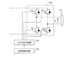
第1のアーム10は、送電回路14と、送電アンテナ12と、リニアアクチュエータ30とを有している。送電回路14は、インバータ回路14aと、パルス出力回路14bと、送電制御回路14cと、送電側受信器14dとを有している。パルス出力回路14bは、例えばゲートドライバ回路であり、送電制御回路14cからの指示に応答してインバータ回路14aの複数のスイッチング素子にパルス信号を供給する。送電制御回路14cは、例えばマイクロコントローラ(マイコン)などの、メモリとプロセッサとを有する集積回路である。メモリに格納されたコンピュータプログラムをプロセッサが実行することにより、パルス出力回路14bおよびリニアアクチュエータ30などの制御を行う。
The
インバータ回路14aおよびリニアアクチュエータ30は、外部の電源5に接続され、電源5から直流電力を受ける。インバータ回路14aは供給された直流電力を交流電力に変換して出力する。リニアアクチュエータ30は、供給された直流電力によって駆動され、第2のアーム20を移動させる。
The
第2のアーム20における受電回路24は、整流回路24aと、受電制御回路24bと、受電側送信器24cとを有している。整流回路24aは、例えば単相全波整流回路または単相半波整流回路等の公知の整流回路である。整流回路24aは、受電アンテナ22から出力された交流電力を直流電力に変換して出力する。受電制御回路24bは、整流回路24aから出力された直流電圧の値を測定し、受電側送信器24cに送信の指示を出す。
The
受電側送信器24cは、送電側受信器14dに、電力伝送に必要な情報を送信する。そのような情報は、例えばエンドエフェクタ90に供給される電力または電圧の値を示す情報であり得る。その情報を受けて、送電制御回路14cは、例えば一定の電圧がエンドエフェクタ90に供給されるように維持するフィードバック制御を行う。受電側送信器24cと送電側受信器14dとの間の通信は、例えば振幅変調または無線LANなどの公知の方法で行うことができる。振幅変調による通信を行う場合、受電側送信器24cは、整流回路24aの前段または後段に接続された負荷変調回路を含み得る。送電側受信器14dは、例えばインバータ回路14aと送電アンテナ12との間の電圧の振幅の変化に基づいて情報を読み取る復調回路を有し得る。
The power receiving
エンドエフェクタ(負荷)90は、この例では、蓄電装置91と、動力装置92とを有する。蓄電装置91は、二次電池またはキャパシタであり、供給された電力を蓄える。動力装置92は、1つまたは複数のモータを含む。蓄電装置91は、不要であれば省略してもよい。
The end effector (load) 90 includes a
図12Bは、電動装置100の他の構成例を示す図である。この例では、リニアアクチュエータ30のモータが、第2のアーム20に搭載されている。リニアアクチュエータ30には、整流回路24aから出力された直流電力が供給される。これにより、リニアアクチュエータ30は、第1のアーム10に対して第2のアーム20を移動させる。
FIG. 12B is a diagram showing another configuration example of the
以下、各構成要素をより詳細に説明する。 Hereinafter, each component will be described in more detail.
図13は、送電アンテナ12および受電アンテナ22の等価回路を示す図である。送電アンテナ12および受電アンテナ22の各々は、図13に示すようなコイル及びキャパシタを含む共振回路の構成を有する。各アンテナは、直列共振回路に限らず、並列共振回路であってもよい。コイル12a、22aは、例えば、回路基板上に形成された平面コイルもしくは積層コイル、または、銅線、リッツ線、もしくはツイスト線などを用いた巻き線コイルであり得る。各キャパシタには、例えばチップ形状またはリード形状を有するあらゆるタイプのキャパシタを利用できる。空気を介した2配線間の容量を各キャパシタとして機能させることも可能である。各コイルが有する自己共振特性をこれらのキャパシタの代わりに用いてもよい。
FIG. 13 is a diagram showing an equivalent circuit of the
共振回路の共振周波数f0は、典型的には、電力伝送時の伝送周波数fに一致するように設定される。共振回路の各々の共振周波数f0は、伝送周波数fに厳密に一致していなくてもよい。共振周波数f0は、例えば、伝送周波数fの50〜150%程度の範囲内の値に設定されていてもよい。電力伝送の周波数fは、例えば50Hz〜300GHz、より好ましくは20kHz〜10GHz、さらに好ましくは20kHz〜20MHz、さらに好ましくは20kHz〜1MHzに設定され得る。 The resonance frequency f0 of the resonance circuit is typically set to match the transmission frequency f at the time of power transmission. Each resonance frequency f0 of the resonance circuit does not have to exactly match the transmission frequency f. The resonance frequency f0 may be set to a value within the range of, for example, about 50 to 150% of the transmission frequency f. The frequency f of the power transmission can be set to, for example, 50 Hz to 300 GHz, more preferably 20 kHz to 10 GHz, still more preferably 20 kHz to 20 MHz, still more preferably 20 kHz to 1 MHz.
直流電源5は、例えば、商用電源、一次電池、二次電池、太陽電池、燃料電池、USB(Universal Serial Bus)電源、高容量のキャパシタ(例えば電気二重層キャパシタ)、商用電源に接続された電圧変換器などの任意の電源であってよい。
The direct
図14Aは、インバータ回路14aの構成例を示す図である。インバータ回路14aは、パルス出力回路14bから供給されたパルス信号に応じて導通/非導通の状態を変化させる複数のスイッチング素子S1〜S4を有する。各スイッチング素子の導通/非導通の状態を変化させることにより、入力された直流電力を交流電力に変換することができる。図14Aに示す例では、4つのスイッチング素子S1〜S4を含むフルブリッジ型のインバータ回路が用いられている。この例では、各スイッチング素子はIGBT(Insulated−gate bipolar transistor)であるが、MOSFET(Metal Oxide Semiconductor Field−Effect Transistor)などの他の種類のスイッチング素子を用いてもよい。
FIG. 14A is a diagram showing a configuration example of the
図14Aに示す例では、4つのスイッチング素子S1〜S4のうち、スイッチング素子S1およびS4(第1スイッチング素子対と称する。)は、供給された直流電圧と同じ極性の電圧を導通時に出力する。一方、スイッチング素子S2およびS3(第2スイッチング素子対と称する。)は、供給された直流電圧と逆の極性の電圧を導通時に出力する。パルス出力回路14bは、制御回路14cからの指示に従い、4つのスイッチング素子S1〜S4のゲートにパルス信号を供給する。この際、第1スイッチング素子対(S1およびS4)に供給する2つのパルス信号の位相差、および第2スイッチング素子対(S2およびS3)に供給する2つのパルス信号の位相差を調整することにより、出力される電圧の振幅を制御することができる。
In the example shown in FIG. 14A, of the four switching elements S1 to S4, the switching elements S1 and S4 (referred to as the first switching element pair) output a voltage having the same polarity as the supplied DC voltage at the time of conduction. On the other hand, the switching elements S2 and S3 (referred to as a second switching element pair) output a voltage having a polarity opposite to the supplied DC voltage when conducting. The
図14Bは、インバータ回路14aの他の構成例を示す図である。この例におけるインバータ回路14aは、ハーフブリッジ型のインバータ回路である。ハーフブリッジ型のインバータ回路を用いる場合には、前述の位相制御は適用できない。この場合には、各スイッチング素子に入力されるパルス信号のデューティ比を制御することによって出力電圧の振幅を制御できる。
FIG. 14B is a diagram showing another configuration example of the
図14Bに示すインバータ回路14aは、2つのスイッチング素子S1、S2と2つのキャパシタとを含むハーフブリッジ型のインバータ回路である。2つのスイッチング素子S1、S2と、2つのキャパシタC1、C2とは、並列に接続されている。送電アンテナ12の一端は2つのスイッチング素子S1、S2の間の点に接続され、他端は2つのキャパシタC1、C2の間の点に接続されている。
The
制御回路14cおよびパルス出力回路14bは、スイッチング素子S1、S2を交互にオンにするように、パルス信号を各スイッチング素子に供給する。これにより、直流電力が交流電力に変換される。
The
この例では、パルス信号のデューティ比(即ち、1周期のうち、オンにする期間の割合)を調整することにより、出力電圧Vの出力時間比(即ち、1周期のうち、ゼロではない値をとる期間の割合)を調整できる。これにより、送電アンテナ12に入力される交流電力の電圧の振幅を調整することができる。このようなデューティ制御は、図14Aに示すようなフルブリッジ型のインバータ回路を用いた場合も同様に適用できる。
In this example, by adjusting the duty ratio of the pulse signal (that is, the ratio of the period to be turned on in one cycle), the output time ratio of the output voltage V (that is, the non-zero value in one cycle) is set. The percentage of the period taken) can be adjusted. Thereby, the amplitude of the voltage of the AC power input to the
図15は、整流回路24aの構成例を模式的に示す図である。この例では、整流回路24aは、ダイオードブリッジと平滑コンデンサとを含む全波整流回路である。整流回路24aは、他の整流器の構成を有していてもよい。整流回路24aは、受け取った交流エネルギを負荷であるエンドエフェクタ90が利用可能な直流エネルギに変換して出力する。
FIG. 15 is a diagram schematically showing a configuration example of the
本実施形態によれば、第1のアーム10と第2のアーム20との間の可動部で、非接触で電力が伝送される。このため、電力を伝送するケーブルを排除することができる。その結果、エンドエフェクタの可動域の制約を削減することが出来る。また、図2Aおよび図2Bを参照して説明したケーブルの劣化または断線の問題を解決することができる。
According to the present embodiment, electric power is transmitted in a non-contact manner at a movable portion between the
(実施形態2)
図16は、本開示の実施形態2における電動装置100の構成を示す図である。本実施形態の電動装置100は、アームを伸縮させる機構の代わりに、アーム10を支持体50が延びる方向に沿って移動させる機構を備えている点で、実施形態1とは異なる。
(Embodiment 2)
FIG. 16 is a diagram showing the configuration of the
電動装置100は、第1の方向(図示される例ではY方向)に延びたアーム10と、第1の方向とは異なる第2の方向に延び、アーム10を支持する支持体50と、支持体50またはアーム10に設けられ、アーム10を第2の方向に移動させるリニアアクチュエータ40とを備えている。支持体50は、送電アンテナ52と、送電アンテナ52に接続された送電回路54とを有している。送電回路54は、交流電力を送電アンテナ52に供給するインバータ回路を含む。アーム10は、受電アンテナ13と、受電アンテナ13に接続された受電回路16とを有している。受電回路16は、受電アンテナ13が受け取った交流電力を直流電力に変換してエンドエフェクタ(負荷)90に供給する整流回路を有する。受電アンテナ13とエンドエフェクタ90とはケーブル80で接続されている。
The
本実施形態では、支持体50における送電アンテナ52が、アーム10における受電アンテナ13に非接触で電力を供給する。受電アンテナ13は、受電回路16を介して受電アンテナ13に電気的に接続されたエンドエフェクタ90へ、供給された電力を供給する。
In the present embodiment, the
送電アンテナ52は、送電コイル52aを含み、受電アンテナ13は、受電コイル13aを含む。送電アンテナ52および受電アンテナ13の構成は、実施形態1における送電アンテナ12および受電アンテナ22の構成と同様である。すなわち、送電コイル52aは、受電コイル13aに電磁的に結合して受電コイル13aに非接触で電力を供給する。送電コイル52aの外周で囲まれる送電面および受電コイル13aの外周で囲まれる受電面は、アーム10に加わる荷重の方向に平行である。
The
送電アンテナ52に接続された送電回路54および受電アンテナ13に接続された受電回路16の構成は、実施形態1における送電回路14および受電回路24の構成とそれぞれ同じである。送電回路54は、外部の電源と送電アンテナ52との間に接続されたインバータ回路を有する。インバータ回路から送電アンテナ52に交流電力が供給される。受電回路16は、受電アンテナ13とエンドエフェクタ90との間に接続された整流回路を有する。整流回路からエンドエフェクタ90に、ケーブル80を介して直流電力が供給される。
The configurations of the
本実施形態では、アーム10が延びる方向(第1の方向)が水平方向に平行であり、支持体50が延びる方向(第2の方向)が鉛直方向に平行である。しかし、このような構成に限定されず、例えば図17に示すように、第1の方向が鉛直方向に平行で、第2の方向が水平方向に平行であってもよい。
In the present embodiment, the direction in which the
図18は、支持体50およびアーム10の構成をより詳細に示す図である。図示されるように、支持体50における送電コイル52aは、アーム10における受電コイル13aよりも、第2の方向(この例ではZ方向)に長い形状の巻線を有する。これにより、リニアアクチュエータ40がアーム10を第2の方向に移動させても送電コイル52aと受電コイル13aとの対向状態が維持される。
FIG. 18 is a diagram showing the configuration of the
リニアアクチュエータ40は、支持体50に設けられていてもよいし、アーム10に設けられていてもよい。リニアアクチュエータ40を構成する複数の部品の一部が支持体50に設けられ、他の一部がアーム10に設けられていてもよい。リニアアクチュエータ40におけるモータが支持体50に設けられている場合、外部の直流電源から出力された直流電力が、送電回路54だけでなくリニアアクチュエータ40にも供給される。リニアアクチュエータ40におけるモータがアーム10に設けられている場合、受電回路16から出力された直流電力が、エンドエフェクタ90だけでなくリニアアクチュエータ40にも供給される。
The
本実施形態における送電コイル52aおよび受電コイル13aは、実施形態1と同様、送電コイル52aの送電面および受電コイル13aの受電面が、アーム10に加わる荷重の方向に平行になるように配置されている。これにより、結合係数の変動を抑制することができる。
Similar to the first embodiment, the
図19Aおよび図19Bは、この効果を説明するための図である。図19Aは、本実施形態の構成においてアーム10に加わる荷重が変化したときの影響を示している。図19Bは、本実施形態の変形例の構成においてアーム10に加わる荷重が変化したときの影響を示している。図19Aの例のように、送電面および受電面が荷重による力のモーメントの方向に垂直であれば、エンドエフェクタ90が重量物を保持している場合でも、コイル間の対向状態が崩れにくいため、結合係数の変化を抑制できる。一方、図19Bの例のように、送電面および受電面が荷重による力のモーメントの方向に平行である場合、エンドエフェクタ90が重量物を保持すると、コイル間の対向状態が崩れやすいため、結合係数の変化が比較的大きくなる。
19A and 19B are diagrams for explaining this effect. FIG. 19A shows the effect when the load applied to the
次に、本実施形態の変形例を説明する。 Next, a modified example of this embodiment will be described.
図20は、本実施形態の変形例を示す図である。図示される電動装置100は、図16に示す構成に加えて、実施形態1のように、アームが伸縮する機構をさらに備えている。この電動装置100は、実施形態1と同様、先端にエンドエフェクタ90が設けられた第2のアーム20と、第2のアーム20を第1のアーム10に対して第1の方向(この例ではY方向)に移動させるリニアアクチュエータ30を備えている。これにより、エンドエフェクタ90を第2の方向(Z方向)だけでなく、第1の方向(Y方向)にも移動させることができる。
FIG. 20 is a diagram showing a modified example of the present embodiment. In addition to the configuration shown in FIG. 16, the illustrated
本実施形態では、第1のアーム10が、受電アンテナ13と、送電アンテナ12と、これらの間に接続された受電回路16および送電回路14とを有している。第2のアーム20は、受電アンテナ22とエンドエフェクタ90(負荷)との間に接続された受電回路24を有している。
In the present embodiment, the
図21は、図20に示す電動装置100の構成を示すブロック図である。この例では、第1のアーム10が、受電回路16および送電回路14の両方を備えている。受電回路16は、受電アンテナ13とリニアアクチュエータ30との間に接続された整流回路16aと、受電制御回路16bと、受電側送信器16cとを有している。受電回路16の構成は、第2のアーム20における受電回路24と同様である。送電回路14は、整流回路16aと送電アンテナ12との間に接続されたインバータ回路14aと、パルス出力回路14bと、送電制御回路14cと、送電側受信器14dとを有している。送電回路14の構成は、支持体50における送電回路54の構成と同様である。この例では、第1のアーム10におけるリニアアクチュエータ30のモータは、整流回路16aから出力された直流電力によって動作し、第2のアーム20をY方向に移動させる。
FIG. 21 is a block diagram showing the configuration of the
図21の構成例では、第2のアーム20を第1の方向(Y方向)に移動させるリニアアクチュエータ30が第1のアーム10に設けられているが、図12Bを参照して説明したように、第2のアーム20がリニアアクチュエータ30を有していてもよい。その場合、受電アンテナ22とリニアアクチュエータ30との間、かつ受電アンテナ22と負荷(エンドエフェクタ90)との間に整流回路24aが接続される。同様に、第1のアーム10を第2の方向(Z方向)に移動させるリニアアクチュエータ40は、第1のアーム10に設けられていてもよい。その場合、リニアアクチュエータ40は、リニアアクチュエータ30と同様、整流回路16aの後段に接続され、整流回路16aからの直流電力によって動作する。
In the configuration example of FIG. 21, a
図21からわかるように、本実施形態の電動装置100は、多段接続の無線電力伝送システムであるといえる。支持体50は送電装置に相当し、第1のアーム10は、送電および受電を行う中継装置に相当し、第2のアーム20は受電装置に相当する。
As can be seen from FIG. 21, it can be said that the
本実施形態の電動装置100は、図20に示すように、第2の方向(Z方向)に平行な軸の周りに支持体50、第1のアーム10、第2のアーム20、およびエンドエフェクタ90を回転させる回転機構60を備えている。図21にはこの回転機構60の図示が省略されているが、回転機構60についても、送電アンテナおよび受電アンテナを介した無線電力伝送が適用され得る。回転機構60も、電源5からの電力によって駆動される。
As shown in FIG. 20, the
電動装置100は、回転機構60に加えて、または回転機構60に代えて、支持体50に支持された第2の回転機構をさらに備えていてもよい。そのような第2の回転機構は、例えば第1のアーム10を、第2の方向(図20の例ではZ方向)に平行な軸、および第1および第2の方向の両方に垂直な軸(図20の例ではX方向)の少なくとも一方の軸の周りに回転させるモータを備える。これにより、エンドエフェクタ90の移動の自由度をさらに高めることができる。
The
図22は、そのような第2の回転機構60Aを有する電動装置100の一例を模式的に示す図である。この例における電動装置100は、X方向の回転軸の周りに第1のアーム10を回転させる第2の回転機構60Aを有している。これにより、アーム10、20、およびエンドエフェクタ90を、上下方向にも移動させることができる。
FIG. 22 is a diagram schematically showing an example of an
以上の実施形態では、第2のアーム20は1段のアームであるが、連結された複数段のアームを第2のアーム20としてもよい。そのような第2のアーム20は、位置および姿勢を決めるための1つ以上の関節が付加される。自由度を大きくするため、6軸または7軸といった多くの関節を設けた構成も可能である。以下、そのような構成の例を説明する。
In the above embodiment, the
図23Aは、第2のアーム20が、関節(回転機構)60B、60Cを介して連結された複数の部分を含む例を示している。図23Bは、第2のアーム20が、関節60Bを介して連結された複数の部分を含み、先端部において伸縮機構を有する例を示している。図23Cは、第2のアーム20が、関節60B、60Cを介して連結された複数の部分を含む他の例を示している。図23Cの例では、関節60Cの軸の方向が図23Aの例とは異なっている。図23Dは、第1のアームと第2のアーム20との間の伸縮機構がないが、第2のアーム20が、関節60B、60Cを有する例を示している。これらのいずれの構成においても、エンドエフェクタ90の移動の自由度を大きく向上させることができる。これらの例では、第2のアーム20の内部で複数段の無線電力伝送が行われ得る。複数段の無線電力伝送は、例えば図21に示す第1のアーム10のような中継装置を、複数個連続させた構造を有する。
FIG. 23A shows an example in which the
このように、エンドエフェクタ90は、第1のアーム10に直接連結されたアームの部分に接続されている必要はなく、第2のアーム20を構成する複数のアーム部分の先端に設けられ得る。
As described above, the
(実施形態3)
次に、本開示の実施形態3を説明する。本実施形態の電動装置は、実施形態1と同様、アームを支持体に対して回転させる回転機構と、アームを伸縮させる直動機構とを備えている。本実施形態においては、アームの先端のエンドエフェクタを回転移動させる際に、まずアームを縮めてから、回転移動を行う。これにより、回転に必要なトルクを低減し、消費電力を抑えることができる。
(Embodiment 3)
Next, the third embodiment of the present disclosure will be described. Similar to the first embodiment, the electric device of the present embodiment includes a rotation mechanism for rotating the arm with respect to the support and a linear motion mechanism for expanding and contracting the arm. In the present embodiment, when the end effector at the tip of the arm is rotationally moved, the arm is first contracted and then the end effector is rotationally moved. As a result, the torque required for rotation can be reduced and power consumption can be suppressed.
物体が回転動作を行うときの慣性モーメントは、その物体の各部分の質量と、その部分から回転軸までの距離の2乗との積を、物体全体にわたって積分した値である。したがって、アームを伸ばした状態で回転させる場合、アームを縮めた状態で回転させる場合よりも、慣性モーメントが大きくなる。その結果、アームの重心が中心から離れるほど、大きな加減速トルクが必要となり、モータへの負荷が大きくなる。また、回転のために広いスペースが必要となる。 The moment of inertia when an object rotates is a value obtained by integrating the product of the mass of each part of the object and the square of the distance from that part to the axis of rotation over the entire object. Therefore, when the arm is rotated in the extended state, the moment of inertia is larger than when the arm is rotated in the contracted state. As a result, the farther the center of gravity of the arm is from the center, the larger the acceleration / deceleration torque is required, and the greater the load on the motor. In addition, a large space is required for rotation.
このような課題を解決するため、本実施形態では、アームの重心を中心軸に近づけてから回転を開始する制御が行われる。これにより、モータへの負荷を小さくし、空間的にもコンパクトな移動が可能となる。 In order to solve such a problem, in the present embodiment, control is performed in which the center of gravity of the arm is brought closer to the central axis and then rotation is started. This reduces the load on the motor and enables spatially compact movement.
図24は、本実施形態における電動装置100の構成を模式的に示す図である。この電動装置100は、実施形態1における電動装置100と同様の構造を有している。すなわち、電動装置100は、第1の方向に延びた第1のアーム10と、第1のアーム10に支持された第2のアーム20と、第1のアーム10または第2のアーム20に設けられ、第2のアーム20を第1のアーム10に対して第1の方向に移動させるリニアアクチュエータ30と、第1の方向と異なる第2の方向に延び、第1のアーム10を支持する支持体50と、第2の方向に平行な回転軸の周りに支持体50を回転させる回転機構60とを備えている。回転機構60は、モータを有し、モータの回転によって支持体50を回転させる。第1のアーム10は、送電アンテナを有し、第2のアームは、受電アンテナを有する。送電アンテナは、受電アンテナへ非接触で電力を供給する。受電アンテナは、受電アンテナに電気的に接続された負荷へ供給された電力を供給する。
FIG. 24 is a diagram schematically showing the configuration of the
本実施形態の電動装置100が実施形態1の電動装置100と異なる点は、回転機構60およびリニアアクチュエータ30の動作にある。電動装置100は、支持体50を回転させるとき、まず、リニアアクチュエータ30が、第2のアーム20の重心を、上記回転軸に近づける。すなわち、図24に示す配置では、リニアアクチュエータ30は、第2のアーム20を−Y方向に移動させる。その後、回転機構60が、支持体50を所望の角度だけ回転させる。その後、リニアアクチュエータ30が、第2のアーム20の重心を当該回転軸から遠ざけてエンドエフェクタ90を所望の位置にまで到達させる。
The difference between the
上記の動作を実現するために、電動装置100は、リニアアクチュエータ30および回転機構60におけるそれぞれのモータに電気的に接続された制御回路150を有する。制御回路150は、各モータを制御する制御信号を出力し、上記の動作をリニアアクチュエータ30および回転機構60に実行させる。制御回路150は、例えばマイコンなどの、メモリおよびプロセッサを備えた集積回路であり得る。なお、制御回路150は、電動装置100とは独立した他の装置に設けられていてもよい。そのような外部の制御回路150から、リニアアクチュエータ30および回転機構60に、有線または無線で当該制御信号が送られてもよい。
In order to realize the above operation, the
図25は、本実施形態における上記動作を模式的に示す概念図である。図中のO点は、回転軸の位置を示し、A点はエンドエフェクタ90の初期位置を示している。図25は、エンドエフェクタ90をA点から、回転軸を中心とする同一半径の円周上のB点まで移動させる場合のエンドエフェクタ90の軌跡を示している。当然のことながら、A点とB点とで、O点からの距離が異なっていてもよい。図25において、黒丸がエンドエフェクタ90の位置を示している。初期状態においてA点にあったエンドエフェクタ90は、アーム20を縮めることにより、A’点に移動する。次に、O点の周りを回転し、B’点に移動する。そして、アーム20を伸ばすことにより、B点に移動する。
FIG. 25 is a conceptual diagram schematically showing the above operation in the present embodiment. Point O in the figure indicates the position of the rotation axis, and point A indicates the initial position of the
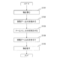
図26は、上記動作において、制御回路150が電動装置100に出す指示の手順を示すフローチャートである。ここでは、エンドエフェクタ90がハンドであり、ハンドが物品を掴んでから所定の位置に移動して当該物品を離すまでの動作を説明する。この動作は、制御回路150のメモリに格納されたコンピュータプログラムを、プロセッサが実行することによって実現され得る。
FIG. 26 is a flowchart showing a procedure of an instruction issued by the
制御回路150は、まず、エンドエフェクタ90に、物を掴む指示を出す(ステップS101)。この指示は、例えば制御回路150からエンドエフェクタ90内の各モータに有線または無線で送られる制御信号によって行われる。エンドエフェクタ90が物を掴むと、制御回路150は、移動アーム20を所定量だけ縮めるようにリニアアクチュエータ30に指示する。移動アーム20を縮める量は、要求される動作速度、回転機構60のモータの性能、および設置場所の空間的な余裕に応じて適宜決定される。次に、制御回路150は、アーム10、20を、所定の角度だけ回転させるように回転機構60に指示する(ステップS103)。回転量は、O点からA点までの線分と、O点からB点までの線分とがなす角度に設定される。次に、制御回路150は、移動アーム20を、目的の長さまで伸ばすようにリニアアクチュエータ30に指示する(ステップS104)。エンドエフェクタ90がB点に到達すると、制御回路150は、エンドエフェクタ90に、物を離すように指示する(ステップS105)。
The
以上の動作により、本実施形態の電動装置100は、回転機構60におけるモータへの負荷を小さくし、空間的にコンパクトにエンドエフェクタ90を移動させることができる。
By the above operation, the
本実施形態のように、先端を縮めてから回転させて再度伸ばすという制御を行う場合、リニアアクチュエータ30による伸縮動作の頻度が高くなる。図2Aおよび図2Bに示す比較例のように、伸縮動作が行われる箇所にケーブルが存在する場合、伸縮時のケーブルを保持するケーブルベア(登録商標)等を設ける必要がある。しかし、そのような構成では、伸縮の度にケーブルが屈曲を繰り返すことになり、ケーブルの劣化および断線に繋がる。このため、定期的にケーブルを交換するなどのメンテナンスが必要になる。これに対し、本実施形態では、伸縮部に無線電力伝送システムを適用し、ケーブルを排除することができる。このため、ケーブルの劣化および断線の問題を解決できる。
When the control of contracting the tip, rotating the tip, and extending the tip again is performed as in the present embodiment, the frequency of expansion / contraction operation by the
(実施形態4)
図27は、本開示の実施形態4における電動装置100の構成を模式的に示す図である。この電動装置100は、回転機構60が支持体50の根元ではなく、支持体50と第1のアーム10との連結部に設けられている点で、実施形態3の電動装置とは異なっている。本実施形態における電動装置100は、支持体50と、支持体50に支持され、回転軸の周りに回転する回転機構60と、第1の方向に延び、回転機構60に連結され、上記回転軸の周りに回転する第1のア−ム10と、第1のアーム10に支持された第2のアーム20と、第1のアーム10または第2のアーム20に設けられ、第2のアーム20を第1のアーム10に対して第1の方向に移動させるリニアアクチュエータ30とを備えている。各構成要素の構造は、実施形態3におけるものと同じである。
(Embodiment 4)
FIG. 27 is a diagram schematically showing the configuration of the
本実施形態では、図27に示すように、回転機構60により、エンドエフェクタ90を、上下に回転移動させることができる。
In the present embodiment, as shown in FIG. 27, the
本実施形態においても、アーム10、20の回転動作を行う際に、実施形態3で説明した課題が生じる。このため、本実施形態においても、実施形態3と同様の制御が行われる。すなわち、第1のアームを回転させるとき、まず、リニアアクチュエータ30が、第2のアーム20の重心を回転軸に近づけ、その後、回転機構60が、第1のアーム10を回転させる。そして、リニアアクチュエータ30が、第2のアーム20の重心を回転軸から遠ざける。このような動作は、制御回路150が回転機構60およびリニアアクチュエータ30のモータを制御することによって実現される。
Also in this embodiment, the problems described in the third embodiment occur when the
本実施形態においても、回転動作を行う際に、一旦第2のアーム20を縮めてから回転が行われる。このため、回転機構60におけるモータへの負荷を小さくし、空間的にコンパクトにエンドエフェクタ90を移動させることができる。
Also in this embodiment, when the rotation operation is performed, the
なお、本実施形態においても、実施形態3と同様に、支持体50を回転させる回転機構60を設けてもよい。その場合、各回転機構60の回転動作を行う際に、上記の制御を行うことで、どの回転動作についても、低負荷かつ省スペースの動作が可能になる。
In this embodiment as well, a
次に、本開示の他の実施形態を例示する。 Next, other embodiments of the present disclosure will be illustrated.
図28は、本開示の他の実施形態を示す図である。この実施形態における電動装置は、第1の方向に延びるアーム10と、第1の方向とは異なる第2の方向に延び、アーム10を支持する支持体50と、支持体50を第2の方向に平行な回転軸の周りに回転させる回転機構60と、アーム10の重心を、第1の方向に移動させるリニアアクチュエータ30とを備えている。リニアアクチュエータ30は、支持体50またはアーム10に設けられる。この実施形態でも、支持体50とアーム10との間は、送電アンテナと受電アンテナとによる無線電力伝送が行われる。
FIG. 28 is a diagram showing another embodiment of the present disclosure. The electric device in this embodiment has an
この実施形態においても、アーム10を回転させるとき、まずリニアアクチュエータ30が、アーム10の重心を、回転機構60の回転軸に近づける。そして、回転機構60が、支持体50を回転させる。その後、リニアアクチュエータ30が、アーム10の重心を、回転機構60の回転軸から遠ざける。
Also in this embodiment, when the
このような動作により、本実施形態においても、回転機構60のモータへの負荷を低減し、省スペースの移動が可能である。
By such an operation, the load on the motor of the
図29Aは、実施形態3における電動装置100の配置の向きを変更した例を示す図である。この例では、電動装置100が壁面に設置されており、水平面に平行なY軸に平行な回転軸の周りにアーム10、20を回転させることができる。
FIG. 29A is a diagram showing an example in which the orientation of the arrangement of the
図29Bは、この例における荷重による力のモーメントの向きを表す図である。図29Bの左側に示すように、アーム10、20がX軸の正方向側に振れているとき、荷重による力のモーメントの向きは、+Y方向である。逆に、図29Bの右側に示すように、アーム10、20がX軸の負方向側に振れているとき、荷重による力のモーメントの向きは、−Y方向である。このモーメントによる送電コイルと受電コイルとの結合係数への影響を抑えるために、この例では、送電コイルの送電面および受電コイルの受電面が、XZ面に平行になるように配置されている。
FIG. 29B is a diagram showing the direction of the moment of force due to the load in this example. As shown on the left side of FIG. 29B, when the
図30Aは、実施形態4における電動装置100の配置の向きを変更した例を示す図である。この例では、電動装置100が壁面に設置されており、水平面に平行なX軸に平行な回転軸の周りにアーム10、20を回転させることができる。
FIG. 30A is a diagram showing an example in which the orientation of the arrangement of the
図30Bは、この例における荷重による力のモーメントの向きを表す図である。図30Bの左側に示すように、アーム10、20がY軸の負方向側に振れているとき、荷重による力のモーメントの向きは、+X方向である。逆に、図30Bの右側に示すように、アーム10、20がY軸の正方向側に振れているとき、荷重による力のモーメントの向きは、−X方向である。このモーメントによる送電コイルと受電コイルとの結合係数への影響を抑えるために、この例でも、送電コイルの送電面および受電コイルの受電面が、ZY面面に平行になるように配置されている。
FIG. 30B is a diagram showing the direction of the moment of force due to the load in this example. As shown on the left side of FIG. 30B, when the
以上のように、本開示は、以下の項目に記載の電動装置および制御方法を含む。 As described above, the present disclosure includes the electric device and the control method described in the following items.
[項目1]
第1の方向に延びた第1のア−ムと、
前記第1のアームに支持された第2のアームと、
前記第1のアームまたは前記第2のアームに設けられ、前記第2のアームを前記第1のアームに対して前記第1の方向に移動させる第1のリニアアクチュエータと、
を備え、
前記第1のアームは、第1の送電アンテナを有し、
前記第2のアームは、第1の受電アンテナを有し、
前記第1の送電アンテナは、前記第1の受電アンテナへ非接触で電力を供給し、
前記第1の受電アンテナは、前記第1の受電アンテナに電気的に接続された負荷へ、前記供給された電力を供給する、
電動装置。
[Item 1]
With the first arm extending in the first direction,
A second arm supported by the first arm and
A first linear actuator provided on the first arm or the second arm and moving the second arm in the first direction with respect to the first arm.
With
The first arm has a first power transmission antenna.
The second arm has a first power receiving antenna.
The first power transmitting antenna supplies power to the first power receiving antenna in a non-contact manner.
The first power receiving antenna supplies the supplied power to a load electrically connected to the first power receiving antenna.
Electric device.
[項目2]
前記第1の送電アンテナは、第1の送電コイルを含み、
前記第1の受電アンテナは、第1の受電コイルを含み、
前記第1の送電コイルは、前記第1の受電コイルに電磁的に結合して前記第1の受電コイルに非接触で前記電力を供給する、
項目1に記載の電動装置。
[Item 2]
The first power transmission antenna includes a first power transmission coil.
The first power receiving antenna includes a first power receiving coil.
The first power transmission coil is electromagnetically coupled to the first power receiving coil to supply the power to the first power receiving coil in a non-contact manner.
The electric device according to
[項目3]
前記第1の送電コイルは、前記第1の送電コイルの外周で囲まれる第1の送電面を有し、
前記第1の受電コイルは、前記第1の受電コイルの外周で囲まれる第1の受電面を有し、
前記第1の送電面および前記第1の受電面は、前記第2のアームに加わる荷重の方向に平行である、
項目2に記載の電動装置。
[Item 3]
The first power transmission coil has a first power transmission surface surrounded by the outer circumference of the first power transmission coil.
The first power receiving coil has a first power receiving surface surrounded by the outer circumference of the first power receiving coil.
The first power transmitting surface and the first power receiving surface are parallel to the direction of the load applied to the second arm.
The electric device according to
[項目4]
前記第1の方向と異なる第2の方向に延び、前記第1のアームを支持する支持体をさらに備えた、
項目1から3のいずれか1項に記載の電動装置。
[Item 4]
A support extending in a second direction different from the first direction and supporting the first arm is further provided.
The electric device according to any one of
[項目5]
前記支持体または前記第1のアームに設けられ、前記第1のアームを前記第2の方向に移動させる第2のリニアアクチュエータをさらに備え、
前記支持体は、第2の送電アンテナを有し、
前記第1のアームは、第2の受電アンテナをさらに有し、
前記第2の送電アンテナは、前記第2の受電アンテナへ非接触で電力を供給する、
項目4に記載の電動装置。
[Item 5]
A second linear actuator provided on the support or the first arm and for moving the first arm in the second direction is further provided.
The support has a second power transmission antenna.
The first arm further comprises a second power receiving antenna.
The second power transmitting antenna supplies power to the second power receiving antenna in a non-contact manner.
The electric device according to item 4.
[項目6]
前記第2の送電アンテナは、第2の送電コイルを含み、
前記第2の受電アンテナは、第2の受電コイルを含み、
前記第2の送電コイルは、前記第2の受電コイルに電磁的に結合して前記第2の受電コイルに非接触で電力を供給する、
項目5に記載の電動装置。
[Item 6]
The second power transmission antenna includes a second power transmission coil.
The second power receiving antenna includes a second power receiving coil.
The second power transmission coil is electromagnetically coupled to the second power receiving coil to supply power to the second power receiving coil in a non-contact manner.
The electric device according to
[項目7]
前記第2の送電コイルは、前記第2の送電コイルの外周で囲まれる第2の送電面を有し、
前記第2の受電コイルは、前記第2の受電コイルの外周で囲まれる第2の受電面を有し、
前記第2の送電面および前記第2の受電面は、前記第1のアームに加わる荷重の方向に平行である、
項目6に記載の電動装置。
[Item 7]
The second power transmission coil has a second power transmission surface surrounded by the outer circumference of the second power transmission coil.
The second power receiving coil has a second power receiving surface surrounded by the outer circumference of the second power receiving coil.
The second power transmitting surface and the second power receiving surface are parallel to the direction of the load applied to the first arm.
The electric device according to item 6.
[項目8]
前記第1のアームが前記第1のリニアアクチュエータを有し、
前記第1のアームは、
前記第2の受電アンテナと前記第1のリニアアクチュエータとの間に接続された第1の整流回路と、
前記第1の整流回路と前記第1の送電アンテナとの間に接続された第1のインバータ回路と、
をさらに有し、
前記第2のアームは、前記第1の受電アンテナと前記負荷との間に接続された第2の整流回路をさらに有する、
項目5から7のいずれか1項に記載の電動装置。
[Item 8]
The first arm has the first linear actuator.
The first arm
A first rectifier circuit connected between the second power receiving antenna and the first linear actuator,
A first inverter circuit connected between the first rectifier circuit and the first power transmission antenna,
Have more
The second arm further comprises a second rectifier circuit connected between the first power receiving antenna and the load.
The electric device according to any one of
[項目9]
前記第2のアームが前記第1のリニアアクチュエータを有し、
前記第2のアームは、前記第1の受電アンテナと前記第1のリニアアクチュエータとの間、かつ前記第1の受電アンテナと前記負荷との間に接続された整流回路をさらに有する、
項目5から7のいずれか1項に記載の電動装置。
[Item 9]
The second arm has the first linear actuator.
The second arm further includes a rectifying circuit connected between the first power receiving antenna and the first linear actuator, and between the first power receiving antenna and the load.
The electric device according to any one of
[項目10]
前記第2の方向に平行な軸の周りに前記支持体を回転させる第1の回転機構をさらに有する、項目5から9のいずれか1項に記載の電動装置。
[Item 10]
The electric device according to any one of
[項目11]
前記支持体に支持され、前記第1のアームを、前記第2の方向に平行な軸、および前記第1および第2の方向の両方に垂直な軸の少なくとも一方の軸の周りに回転させる第2の回転機構をさらに備える、項目5から10のいずれか1項に記載の電動装置。
[Item 11]
A second arm supported by the support that rotates the first arm around at least one axis parallel to the second direction and perpendicular to both the first and second directions. The electric device according to any one of
[項目12]
第2のアームの先端に配置されたエンドエフェクタをさらに備え、
前記負荷は、前記エンドエフェクタである、項目1から11のいずれか1項に記載の電動装置。
[Item 12]
Further equipped with an end effector located at the tip of the second arm,
The electric device according to any one of
[項目13]
第1の方向に延びたアームと、
前記第1の方向と異なる第2の方向に延び、前記アームを支持する支持体と、
前記支持体および前記アームの少なくとも一方に設けられ、前記アームを前記第2の方向に移動させるリニアアクチュエータと、
を備え、
前記支持体は、送電アンテナを有し、
前記アームは、受電アンテナを有し、
前記送電アンテナは、前記受電アンテナへ非接触で電力を供給し、
前記受電アンテナは、前記受電アンテナに電気的に接続された負荷へ、前記供給された電力を供給する、
電動装置。
[Item 13]
With the arm extending in the first direction,
A support extending in a second direction different from the first direction to support the arm, and
A linear actuator provided on at least one of the support and the arm and moving the arm in the second direction.
With
The support has a power transmission antenna and
The arm has a power receiving antenna and has a power receiving antenna.
The power transmitting antenna supplies power to the power receiving antenna in a non-contact manner.
The power receiving antenna supplies the supplied power to a load electrically connected to the power receiving antenna.
Electric device.
[項目14]
前記送電アンテナは、送電コイルを含み、
前記受電アンテナは、受電コイルを含み、
前記送電コイルは、前記受電コイルに電磁的に結合して前記受電コイルに非接触で電力を供給する、
項目13に記載の電動装置。
[Item 14]
The power transmission antenna includes a power transmission coil.
The power receiving antenna includes a power receiving coil.
The power transmission coil is electromagnetically coupled to the power receiving coil to supply power to the power receiving coil in a non-contact manner.
[項目15]
前記送電コイルは、前記送電コイルの外周で囲まれる送電面を有し、
前記受電コイルは、前記受電コイルの外周で囲まれる受電面を有し、
前記送電面および前記受電面は、前記アームに加わる荷重の方向に平行である、
項目14に記載の電動装置。
[Item 15]
The power transmission coil has a power transmission surface surrounded by the outer circumference of the power transmission coil.
The power receiving coil has a power receiving surface surrounded by the outer circumference of the power receiving coil.
The power transmitting surface and the power receiving surface are parallel to the direction of the load applied to the arm.
[項目16]
前記支持体は、前記送電アンテナに接続されたインバータ回路をさらに有し、
前記アームは、前記受電アンテナと前記負荷との間に接続された整流回路をさらに有する、
項目13から15のいずれか1項に記載の電動装置。
[Item 16]
The support further comprises an inverter circuit connected to the power transmission antenna.
The arm further comprises a rectifying circuit connected between the power receiving antenna and the load.
The electric device according to any one of
[項目17]
前記第2の方向に平行な軸の周りに前記支持体を回転させる第1の回転機構をさらに備える、
項目13から16のいずれか1項に記載の電動装置。
[Item 17]
A first rotation mechanism for rotating the support around an axis parallel to the second direction is further provided.
The electric device according to any one of
[項目18]
前記支持体に支持され、前記アームを、前記第2の方向に平行な軸、および前記第1および第2の方向の両方に垂直な軸の少なくとも一方の軸の周りに回転させる第2の回転機構をさらに有する、項目13から17のいずれか1項に記載の電動装置。
[Item 18]
A second rotation that is supported by the support and rotates the arm around at least one axis parallel to the second direction and an axis perpendicular to both the first and second directions. The electric device according to any one of
[項目19]
前記アームの先端に配置されたエンドエフェクタをさらに備え、
前記負荷は、前記エンドエフェクタである、項目13から18のいずれか1項に記載の電動装置。
[Item 19]
Further provided with an end effector located at the tip of the arm
The electric device according to any one of
[項目20]
第1の方向に延びた第1のアームと、
前記第1のアームに支持された第2のアームと、
前記第1のアームまたは前記第2のアームに設けられ、前記第2のアームを前記第1のアームに対して前記第1の方向に移動させるリニアアクチュエータと、
前記第1の方向と異なる第2の方向に延び、前記第1のアームを支持する支持体と、
前記第2の方向に平行な回転軸の周りに前記支持体を回転させる回転機構と、
を備え、
前記第1のアームは、送電アンテナを有し、
前記第2のアームは、受電アンテナを有し、
前記送電アンテナは、前記受電アンテナへ非接触で電力を供給し、
前記受電アンテナは、前記受電アンテナに電気的に接続された負荷へ前記供給された電力を供給し、
前記支持体を回転させるとき、
まず、前記リニアアクチュエータが、前記第2のアームの重心を前記回転軸に近づけ、
その後、前記回転機構が、前記支持体を回転させる、
電動装置。
[Item 20]
The first arm extending in the first direction,
A second arm supported by the first arm and
A linear actuator provided on the first arm or the second arm and moving the second arm in the first direction with respect to the first arm.
A support that extends in a second direction different from the first direction and supports the first arm,
A rotation mechanism that rotates the support around a rotation axis parallel to the second direction,
With
The first arm has a power transmission antenna.
The second arm has a power receiving antenna and has a power receiving antenna.
The power transmitting antenna supplies power to the power receiving antenna in a non-contact manner.
The power receiving antenna supplies the supplied power to a load electrically connected to the power receiving antenna.
When rotating the support
First, the linear actuator brings the center of gravity of the second arm closer to the rotation axis.
After that, the rotation mechanism rotates the support.
Electric device.
[項目21]
前記支持体を回転させるとき、
まず、前記リニアアクチュエータが、前記第2のアームの重心を前記回転軸に近づけ、
その後、前記回転機構が、前記支持体を回転させ、
その後、前記リニアアクチュエータが、前記第2のアームの前記重心を前記回転軸から遠ざける、
項目20に記載の電動装置。
[Item 21]
When rotating the support
First, the linear actuator brings the center of gravity of the second arm closer to the rotation axis.
After that, the rotation mechanism rotates the support, and the support is rotated.
The linear actuator then moves the center of gravity of the second arm away from the axis of rotation.
The electric device according to
[項目22]
前記リニアアクチュエータおよび前記回転機構を制御する制御回路をさらに備え、
前記支持体を回転させるとき、
前記制御回路は、
まず、前記リニアアクチュエータを制御して、前記第2のアームの重心を前記回転軸に近づけ、
その後、前記回転機構を制御して、前記支持体を回転させる、
項目20または21に記載の電動装置。
[Item 22]
A control circuit for controlling the linear actuator and the rotation mechanism is further provided.
When rotating the support
The control circuit
First, the linear actuator is controlled to bring the center of gravity of the second arm closer to the rotation axis.
After that, the rotation mechanism is controlled to rotate the support.
The electric device according to
[項目23]
前記支持体を回転させるとき、
前記制御回路は、
まず、前記リニアアクチュエータを制御して、前記第2のアームの重心を前記回転軸に近づけ、
その後、前記回転機構を制御して、前記支持体を回転させ、
その後、前記リニアアクチュエータを制御して、前記第2のアームの前記重心を前記回転軸から遠ざける、
項目22に記載の電動装置。
[Item 23]
When rotating the support
The control circuit
First, the linear actuator is controlled to bring the center of gravity of the second arm closer to the rotation axis.
After that, the rotation mechanism is controlled to rotate the support, and the support is rotated.
After that, the linear actuator is controlled to move the center of gravity of the second arm away from the rotation axis.
[項目24]
前記回転機構は、モータを有し、前記モータの回転によって前記支持体を回転させる、項目20から23のいずれか1項に記載の電動装置。
[Item 24]
The electric device according to any one of
[項目25]
支持体と、
前記支持体に支持され、回転軸の周りに回転する回転機構と、
第1の方向に延び、前記回転機構に連結され、前記回転軸の周りに回転する第1のア−ムと、
前記第1のアームに支持された第2のアームと、
前記第1のアームまたは前記第2のアームに設けられ、前記第2のアームを前記第1のアームに対して前記第1の方向に移動させるリニアアクチュエータと、
を備え、
前記第1のアームは、送電アンテナを有し、
前記第2のアームは、受電アンテナを有し、
前記送電アンテナは、前記受電アンテナへ非接触で電力を供給し、
前記受電アンテナは、前記受電アンテナに電気的に接続された負荷へ前記供給された電力を供給し、
前記第1のアームを回転させるとき、
まず、前記リニアアクチュエータが、前記第2のアームの重心を前記回転軸に近づけ、
その後、前記回転機構が、前記第1のアームを回転させる、
電動装置。
[Item 25]
With the support
A rotating mechanism that is supported by the support and rotates around a rotating shaft,
A first arm that extends in a first direction, is connected to the rotation mechanism, and rotates around the rotation axis.
A second arm supported by the first arm and
A linear actuator provided on the first arm or the second arm and moving the second arm in the first direction with respect to the first arm.
With
The first arm has a power transmission antenna.
The second arm has a power receiving antenna and has a power receiving antenna.
The power transmitting antenna supplies power to the power receiving antenna in a non-contact manner.
The power receiving antenna supplies the supplied power to a load electrically connected to the power receiving antenna.
When rotating the first arm,
First, the linear actuator brings the center of gravity of the second arm closer to the rotation axis.
After that, the rotation mechanism rotates the first arm.
Electric device.
[項目26]
前記第1のアームを回転させるとき、
まず、前記リニアアクチュエータが、前記第2のアームの重心を前記回転軸に近づけ、
その後、前記回転機構が、前記第1のアームを回転させ、
その後、前記リニアアクチュエータが、前記第2のアームの前記重心を前記回転軸から遠ざける、
項目25に記載の電動装置。
[Item 26]
When rotating the first arm,
First, the linear actuator brings the center of gravity of the second arm closer to the rotation axis.
After that, the rotation mechanism rotates the first arm, and the rotation mechanism causes the first arm to rotate.
The linear actuator then moves the center of gravity of the second arm away from the axis of rotation.
The electric device according to item 25.
[項目27]
前記リニアアクチュエータおよび前記回転機構を制御する制御回路をさらに備え、
前記第1のアームを回転させるとき、
前記制御回路は、
まず、前記リニアアクチュエータを制御して、前記第2のアームの重心を前記回転軸に近づけ、
その後、前記回転機構を制御して、前記第1のアームを回転させる、
項目25または26に記載の電動装置。
[Item 27]
A control circuit for controlling the linear actuator and the rotation mechanism is further provided.
When rotating the first arm,
The control circuit
First, the linear actuator is controlled to bring the center of gravity of the second arm closer to the rotation axis.
After that, the rotation mechanism is controlled to rotate the first arm.
The electric device according to item 25 or 26.
[項目28]
前記第1のアームを回転させるとき、
前記制御回路は、
まず、前記リニアアクチュエータを制御して、前記第2のアームの重心を前記回転軸に近づけ、
その後、前記回転機構を制御して、前記第1のアームを回転させ、
その後、前記リニアアクチュエータを制御して、前記第2のアームの前記重心を前記回転軸から遠ざける、
項目27に記載の電動装置。
[Item 28]
When rotating the first arm,
The control circuit
First, the linear actuator is controlled to bring the center of gravity of the second arm closer to the rotation axis.
After that, the rotation mechanism is controlled to rotate the first arm.
After that, the linear actuator is controlled to move the center of gravity of the second arm away from the rotation axis.
Item 27.
[項目29]
前記回転機構は、モータを有し、前記モータの回転によって前記第2のアームを回転させる、項目25から28のいずれか1項に記載の電動装置。
[Item 29]
The electric device according to any one of items 25 to 28, wherein the rotation mechanism has a motor and rotates the second arm by rotation of the motor.
[項目30]
前記送電アンテナは、送電コイルを含み、
前記受電アンテナは、受電コイルを含み、
前記送電コイルは、前記受電コイルに電磁的に結合して前記受電コイルに非接触で電力を供給する、
項目20から29のいずれか1項に記載の電動装置。
[Item 30]
The power transmission antenna includes a power transmission coil.
The power receiving antenna includes a power receiving coil.
The power transmission coil is electromagnetically coupled to the power receiving coil to supply power to the power receiving coil in a non-contact manner.
The electric device according to any one of
[項目31]
前記送電コイルは、前記送電コイルの外周で囲まれる送電面を有し、
前記受電コイルは、前記受電コイルの外周で囲まれる受電面を有し、
前記送電面および前記受電面は、前記第2のアームに加わる荷重の方向に平行である、
項目30に記載の電動装置。
[Item 31]
The power transmission coil has a power transmission surface surrounded by the outer circumference of the power transmission coil.
The power receiving coil has a power receiving surface surrounded by the outer circumference of the power receiving coil.
The power transmitting surface and the power receiving surface are parallel to the direction of the load applied to the second arm.
The electric device according to
[項目32]
前記第1のアームは、前記送電アンテナに接続されたインバータ回路をさらに有し、
前記第2のアームは、前記受電アンテナと前記負荷との間に接続された整流回路をさらに有する、
項目20から31のいずれか1項に記載の電動装置。
[Item 32]
The first arm further comprises an inverter circuit connected to the power transmission antenna.
The second arm further comprises a rectifying circuit connected between the power receiving antenna and the load.
The electric device according to any one of
[項目33]
第2のアームの先端に配置されたエンドエフェクタをさらに備え、
前記負荷は、前記エンドエフェクタである、項目20から32のいずれか1項に記載の電動装置。
[Item 33]
Further equipped with an end effector located at the tip of the second arm,
The electric device according to any one of
[項目34]
送電アンテナを有し、第1の方向に延びた第1のアームと、
受電アンテナを有し、前記第1のアームに支持された第2のアームと、
前記第1のアームまたは前記第2のアームに設けられ、前記第2のアームを前記第1のアームに対して前記第1の方向に移動させるリニアアクチュエータと、
前記第1の方向と異なる第2の方向に延び、前記第1のアームを支持する支持体と、
前記第2の方向に平行な回転軸の周りに前記支持体を回転させる回転機構と、
を備え、
前記送電アンテナが前記受電アンテナへ非接触で電力を供給し、
前記受電アンテナが前記受電アンテナに電気的に接続された負荷へ前記供給された電力を供給する、
電動装置の制御方法であって、
前記支持体を回転させるとき、
まず、前記リニアアクチュエータを制御して、前記第2のアームの重心を前記回転軸に近づけ、
その後、前記回転機構を制御して、前記支持体を回転させる、
電動装置の制御方法。
[Item 34]
With a first arm that has a power transmission antenna and extends in the first direction,
A second arm having a power receiving antenna and supported by the first arm,
A linear actuator provided on the first arm or the second arm and moving the second arm in the first direction with respect to the first arm.
A support that extends in a second direction different from the first direction and supports the first arm,
A rotation mechanism that rotates the support around a rotation axis parallel to the second direction,
With
The power transmitting antenna supplies power to the power receiving antenna in a non-contact manner.
The power receiving antenna supplies the supplied power to a load electrically connected to the power receiving antenna.
It is a control method for electric devices.
When rotating the support
First, the linear actuator is controlled to bring the center of gravity of the second arm closer to the rotation axis.
After that, the rotation mechanism is controlled to rotate the support.
How to control the electric device.
[項目35]
支持体と、
前記支持体に支持され、回転軸の周りに回転する回転機構と、
第1の方向に延び、前記回転機構に連結され、前記回転軸の周りに回転する第1のア−ムと、
前記第1のアームに支持された第2のアームと、
前記第1のアームまたは前記第2のアームに設けられ、前記第2のアームを前記第1のアームに対して前記第1の方向に移動させるリニアアクチュエータと、
を備え、
前記第1のアームは、送電アンテナを有し、
前記第2のアームは、受電アンテナを有し、
前記送電アンテナは、前記受電アンテナへ非接触で電力を供給し、
前記受電アンテナは、前記受電アンテナに電気的に接続された負荷へ前記供給された電力を供給する、
電動装置の制御方法であって、
前記第1のアームを回転させるとき、
まず、前記リニアアクチュエータを制御して、前記第2のアームの重心を前記回転軸に近づけ、
その後、前記回転機構を制御して、前記第1のアームを回転させる、
電動装置の制御方法。
[Item 35]
With the support
A rotating mechanism that is supported by the support and rotates around a rotating shaft,
A first arm that extends in a first direction, is connected to the rotation mechanism, and rotates around the rotation axis.
A second arm supported by the first arm and
A linear actuator provided on the first arm or the second arm and moving the second arm in the first direction with respect to the first arm.
With
The first arm has a power transmission antenna.
The second arm has a power receiving antenna and has a power receiving antenna.
The power transmitting antenna supplies power to the power receiving antenna in a non-contact manner.
The power receiving antenna supplies the supplied power to a load electrically connected to the power receiving antenna.
It is a control method for electric devices.
When rotating the first arm,
First, the linear actuator is controlled to bring the center of gravity of the second arm closer to the rotation axis.
After that, the rotation mechanism is controlled to rotate the first arm.
How to control the electric device.
[項目36]
前記支持体を回転させた後、前記リニアアクチュエータを制御して、前記第2のアームの前記重心を前記回転軸から遠ざける、項目34または35に記載の電動装置の制御方法。
[Item 36]
34. The method for controlling an electric device according to
本開示の技術は、例えば工場などで用いられるロボットなどの電動装置に利用できる。 The technology of the present disclosure can be used for electric devices such as robots used in factories and the like.
5 電源
10 第1のアーム(固定アーム)
12 第1の送電アンテナ
12a 第1の送電コイル
13 第2の受電アンテナ
13a 第2の送電コイル
14 送電回路
14a インバータ回路
14b 送電制御回路
14c 送電側受信器
16 受電回路
16a 整流回路
16b 受電制御回路
16c 受電側送信器
20 第2のアーム(移動アーム)
22 第1の受電アンテナ
22a 第1の受電コイル
24 受電回路
24a 整流回路
24b 受電制御回路
24c 受電側送信器
30 第1のリニアアクチュエータ
32 モータ
34 ボールねじ
40 第2のリニアアクチュエータ
50 支持体
52 第2の送電アンテナ
52a 第2の送電コイル
54 送電回路
60、60A,60B、60C 回転機構
80 ケーブル
90 エンドエフェクタ(負荷)
100 電動装置
110 伸縮アーム
120 直動アーム
150 制御回路
210 アーム
230 関節
250 支持体
260 回転機構
270 ハンド(エンドエフェクタ)
280 ケーブル
5
12 First
22 First
100
280 cable
Claims (16)
前記第1のアームに支持された第2のアームと、
前記第1のアームまたは前記第2のアームに設けられ、前記第2のアームを前記第1のアームに対して前記第1の方向に移動させるリニアアクチュエータと、
前記第1の方向と異なる第2の方向に延び、前記第1のアームを支持する支持体と、
前記第2の方向に平行な回転軸の周りに前記支持体を回転させる回転機構と、
を備え、
前記第1のアームは、第1の送電アンテナを有し、
前記第2のアームは、第1の受電アンテナを有し、
前記第1の送電アンテナは、前記第1の受電アンテナへ非接触で電力を供給し、
前記第1の受電アンテナは、前記第1の受電アンテナに電気的に接続された負荷へ前記供給された電力を供給し、
前記支持体は、第2の送電アンテナを有し、
前記第1のアームは、第2の受電アンテナと、前記第2の受電アンテナに接続された第1の整流回路と、前記第1の整流回路と前記第1の送電アンテナとの間に接続されたインバータ回路と、をさらに有し、
前記第2のアームは、前記第1の受電アンテナと前記負荷との間に接続された第2の整流回路をさらに有し、
前記リニアアクチュエータは、前記第1の整流回路または前記第2の整流回路から出力された電力によって駆動され、
前記第2の送電アンテナは、前記第2の受電アンテナへ非接触で電力を供給し、
前記第1の送電アンテナは、前記インバータ回路から供給された電力を前記第1の受電アンテナに供給し、
前記支持体を回転させるとき、
まず、前記リニアアクチュエータが、前記第2のアームの重心を前記回転軸に近づけ、
その後、前記回転機構が、前記支持体を回転させる、
電動装置。 The first arm extending in the first direction,
A second arm supported by the first arm and
A linear actuator provided on the first arm or the second arm and moving the second arm in the first direction with respect to the first arm.
A support that extends in a second direction different from the first direction and supports the first arm,
A rotation mechanism that rotates the support around a rotation axis parallel to the second direction,
With
The first arm has a first power transmission antenna.
The second arm has a first power receiving antenna.
The first power transmitting antenna supplies power to the first power receiving antenna in a non-contact manner.
The first power receiving antenna supplies the supplied power to a load electrically connected to the first power receiving antenna.
The support has a second power transmission antenna.
The first arm is connected between the second power receiving antenna, the first rectifier circuit connected to the second power receiving antenna, and the first rectifier circuit and the first power transmission antenna. It also has an inverter circuit,
The second arm further comprises a second rectifier circuit connected between the first power receiving antenna and the load.
The linear actuator is driven by the electric power output from the first rectifier circuit or the second rectifier circuit.
The second power transmitting antenna supplies power to the second power receiving antenna in a non-contact manner.
The first power transmitting antenna supplies the electric power supplied from the inverter circuit to the first power receiving antenna.
When rotating the support
First, the linear actuator brings the center of gravity of the second arm closer to the rotation axis.
After that, the rotation mechanism rotates the support.
Electric device.
まず、前記リニアアクチュエータが、前記第2のアームの重心を前記回転軸に近づけ、
その後、前記回転機構が、前記支持体を回転させ、
その後、前記リニアアクチュエータが、前記第2のアームの前記重心を前記回転軸から遠ざける、
請求項1に記載の電動装置。 When rotating the support
First, the linear actuator brings the center of gravity of the second arm closer to the rotation axis.
After that, the rotation mechanism rotates the support, and the support is rotated.
The linear actuator then moves the center of gravity of the second arm away from the axis of rotation.
The electric device according to claim 1.
前記支持体を回転させるとき、
前記制御回路は、
まず、前記リニアアクチュエータを制御して、前記第2のアームの重心を前記回転軸に近づけ、
その後、前記回転機構を制御して、前記支持体を回転させる、
請求項1または2に記載の電動装置。 A control circuit for controlling the linear actuator and the rotation mechanism is further provided.
When rotating the support
The control circuit
First, the linear actuator is controlled to bring the center of gravity of the second arm closer to the rotation axis.
After that, the rotation mechanism is controlled to rotate the support.
The electric device according to claim 1 or 2.
前記制御回路は、
まず、前記リニアアクチュエータを制御して、前記第2のアームの重心を前記回転軸に近づけ、
その後、前記回転機構を制御して、前記支持体を回転させ、
その後、前記リニアアクチュエータを制御して、前記第2のアームの前記重心を前記回転軸から遠ざける、
請求項3に記載の電動装置。 When rotating the support
The control circuit
First, the linear actuator is controlled to bring the center of gravity of the second arm closer to the rotation axis.
After that, the rotation mechanism is controlled to rotate the support, and the support is rotated.
After that, the linear actuator is controlled to move the center of gravity of the second arm away from the rotation axis.
The electric device according to claim 3.
前記支持体に支持され、回転軸の周りに回転する回転機構と、
第1の方向に延び、前記回転機構に連結され、前記回転軸の周りに回転する第1のア−ムと、
前記第1のアームに支持された第2のアームと、
前記第1のアームまたは前記第2のアームに設けられ、前記第2のアームを前記第1のアームに対して前記第1の方向に移動させるリニアアクチュエータと、
を備え、
前記第1のアームは、第1の送電アンテナを有し、
前記第2のアームは、第1の受電アンテナを有し、
前記第1の送電アンテナは、前記第1の受電アンテナへ非接触で電力を供給し、
前記第1の受電アンテナは、前記第1の受電アンテナに電気的に接続された負荷へ前記供給された電力を供給し、
前記支持体は、第2の送電アンテナを有し、
前記第1のアームは、第2の受電アンテナと、前記第2の受電アンテナに接続された第1の整流回路と、前記第1の整流回路と前記第1の送電アンテナとの間に接続されたインバータ回路と、をさらに有し、
前記第2のアームは、前記第1の受電アンテナと前記負荷との間に接続された第2の整流回路をさらに有し、
前記リニアアクチュエータは、前記第1の整流回路または前記第2の整流回路から出力された電力によって駆動され、
前記第2の送電アンテナは、前記第2の受電アンテナへ非接触で電力を供給し、
前記第1の送電アンテナは、前記インバータ回路から供給された電力を前記第1の受電アンテナに供給し、
前記第1のアームを回転させるとき、
まず、前記リニアアクチュエータが、前記第2のアームの重心を前記回転軸に近づけ、
その後、前記回転機構が、前記第1のアームを回転させる、
電動装置。 With the support
A rotating mechanism that is supported by the support and rotates around a rotating shaft,
A first arm that extends in a first direction, is connected to the rotation mechanism, and rotates around the rotation axis.
A second arm supported by the first arm and
A linear actuator provided on the first arm or the second arm and moving the second arm in the first direction with respect to the first arm.
With
The first arm has a first power transmission antenna.
The second arm has a first power receiving antenna.
The first power transmitting antenna supplies power to the first power receiving antenna in a non-contact manner.
The first power receiving antenna supplies the supplied power to a load electrically connected to the first power receiving antenna.
The support has a second power transmission antenna.
The first arm is connected between the second power receiving antenna, the first rectifier circuit connected to the second power receiving antenna, and the first rectifier circuit and the first power transmission antenna. It also has an inverter circuit,
The second arm further comprises a second rectifier circuit connected between the first power receiving antenna and the load.
The linear actuator is driven by the electric power output from the first rectifier circuit or the second rectifier circuit.
The second power transmitting antenna supplies power to the second power receiving antenna in a non-contact manner.
The first power transmitting antenna supplies the electric power supplied from the inverter circuit to the first power receiving antenna.
When rotating the first arm,
First, the linear actuator brings the center of gravity of the second arm closer to the rotation axis.
After that, the rotation mechanism rotates the first arm.
Electric device.
まず、前記リニアアクチュエータが、前記第2のアームの重心を前記回転軸に近づけ、
その後、前記回転機構が、前記第1のアームを回転させ、
その後、前記リニアアクチュエータが、前記第2のアームの前記重心を前記回転軸から遠ざける、
請求項6に記載の電動装置。 When rotating the first arm,
First, the linear actuator brings the center of gravity of the second arm closer to the rotation axis.
After that, the rotation mechanism rotates the first arm, and the rotation mechanism causes the first arm to rotate.
The linear actuator then moves the center of gravity of the second arm away from the axis of rotation.
The electric device according to claim 6.
前記第1のアームを回転させるとき、
前記制御回路は、
まず、前記リニアアクチュエータを制御して、前記第2のアームの重心を前記回転軸に近づけ、
その後、前記回転機構を制御して、前記第1のアームを回転させる、
請求項6または7に記載の電動装置。 A control circuit for controlling the linear actuator and the rotation mechanism is further provided.
When rotating the first arm,
The control circuit
First, the linear actuator is controlled to bring the center of gravity of the second arm closer to the rotation axis.
After that, the rotation mechanism is controlled to rotate the first arm.
The electric device according to claim 6 or 7.
前記制御回路は、
まず、前記リニアアクチュエータを制御して、前記第2のアームの重心を前記回転軸に近づけ、
その後、前記回転機構を制御して、前記第1のアームを回転させ、
その後、前記リニアアクチュエータを制御して、前記第2のアームの前記重心を前記回転軸から遠ざける、
請求項8に記載の電動装置。 When rotating the first arm,
The control circuit
First, the linear actuator is controlled to bring the center of gravity of the second arm closer to the rotation axis.
After that, the rotation mechanism is controlled to rotate the first arm.
After that, the linear actuator is controlled to move the center of gravity of the second arm away from the rotation axis.
The electric device according to claim 8.
前記第1の受電アンテナは、受電コイルを含み、
前記送電コイルは、前記受電コイルに電磁的に結合して前記受電コイルに非接触で電力を供給する、
請求項1から10のいずれか1項に記載の電動装置。 The first power transmission antenna includes a power transmission coil.
The first power receiving antenna includes a power receiving coil.
The power transmission coil is electromagnetically coupled to the power receiving coil to supply power to the power receiving coil in a non-contact manner.
The electric device according to any one of claims 1 to 10.
前記受電コイルは、前記受電コイルの外周で囲まれる受電面を有し、
前記送電面および前記受電面は、前記第2のアームに加わる荷重の方向に平行である、
請求項11に記載の電動装置。 The power transmission coil has a power transmission surface surrounded by the outer circumference of the power transmission coil.
The power receiving coil has a power receiving surface surrounded by the outer circumference of the power receiving coil.
The power transmitting surface and the power receiving surface are parallel to the direction of the load applied to the second arm.
The electric device according to claim 11.
前記負荷は、前記エンドエフェクタである、請求項1から12のいずれか1項に記載の電動装置。 Further provided with an end effector located at the tip of the second arm
The electric device according to any one of claims 1 to 12, wherein the load is the end effector.
第1の受電アンテナを有し、前記第1のアームに支持された第2のアームと、
前記第1のアームまたは前記第2のアームに設けられ、前記第2のアームを前記第1のアームに対して前記第1の方向に移動させるリニアアクチュエータと、
前記第1の方向と異なる第2の方向に延び、前記第1のアームを支持する支持体と、
前記第2の方向に平行な回転軸の周りに前記支持体を回転させる回転機構と、
を備え、
前記第1の送電アンテナが前記第1の受電アンテナへ非接触で電力を供給し、
前記第1の受電アンテナが前記第1の受電アンテナに電気的に接続された負荷へ前記供給された電力を供給し、
前記支持体は、第2の送電アンテナを有し、
前記第1のアームは、第2の受電アンテナと、前記第2の受電アンテナに接続された第1の整流回路と、前記第1の整流回路と前記第1の送電アンテナとの間に接続されたインバータ回路と、をさらに有し、
前記第2のアームは、前記第1の受電アンテナと前記負荷との間に接続された第2の整流回路をさらに有し、
前記リニアアクチュエータは、前記第1の整流回路または前記第2の整流回路から出力された電力によって駆動され、
前記第2の送電アンテナは、前記第2の受電アンテナへ非接触で電力を供給し、
前記第1の送電アンテナは、前記インバータ回路から供給された電力を前記第1の受電アンテナに供給する、
電動装置の制御方法であって、
前記支持体を回転させるとき、
まず、前記リニアアクチュエータを制御して、前記第2のアームの重心を前記回転軸に近づけ、
その後、前記回転機構を制御して、前記支持体を回転させる、
電動装置の制御方法。 A first arm having a first power transmission antenna and extending in the first direction,
A second arm having a first power receiving antenna and supported by the first arm,
A linear actuator provided on the first arm or the second arm and moving the second arm in the first direction with respect to the first arm.
A support that extends in a second direction different from the first direction and supports the first arm,
A rotation mechanism that rotates the support around a rotation axis parallel to the second direction,
With
The first power transmitting antenna supplies power to the first power receiving antenna in a non-contact manner.
The first power receiving antenna supplies the supplied power to a load electrically connected to the first power receiving antenna.
The support has a second power transmission antenna.
The first arm is connected between the second power receiving antenna, the first rectifier circuit connected to the second power receiving antenna, and the first rectifier circuit and the first power transmission antenna. It also has an inverter circuit,
The second arm further comprises a second rectifier circuit connected between the first power receiving antenna and the load.
The linear actuator is driven by the electric power output from the first rectifier circuit or the second rectifier circuit.
The second power transmitting antenna supplies power to the second power receiving antenna in a non-contact manner.
The first power transmitting antenna supplies the power supplied from the inverter circuit to the first power receiving antenna.
It is a control method for electric devices.
When rotating the support
First, the linear actuator is controlled to bring the center of gravity of the second arm closer to the rotation axis.
After that, the rotation mechanism is controlled to rotate the support.
How to control the electric device.
前記支持体に支持され、回転軸の周りに回転する回転機構と、
第1の方向に延び、前記回転機構に連結され、前記回転軸の周りに回転する第1のア−ムと、
前記第1のアームに支持された第2のアームと、
前記第1のアームまたは前記第2のアームに設けられ、前記第2のアームを前記第1のアームに対して前記第1の方向に移動させるリニアアクチュエータと、
を備え、
前記第1のアームは、第1の送電アンテナを有し、
前記第2のアームは、第1の受電アンテナを有し、
前記第1の送電アンテナは、前記第1の受電アンテナへ非接触で電力を供給し、
前記第1の受電アンテナは、前記第1の受電アンテナに電気的に接続された負荷へ前記供給された電力を供給し、
前記支持体は、第2の送電アンテナを有し、
前記第1のアームは、第2の受電アンテナと、前記第2の受電アンテナに接続された第1の整流回路と、前記第1の整流回路と前記第1の送電アンテナとの間に接続されたインバータ回路と、をさらに有し、
前記第2のアームは、前記第1の受電アンテナと前記負荷との間に接続された第2の整流回路をさらに有し、
前記リニアアクチュエータは、前記第1の整流回路または前記第2の整流回路から出力された電力によって駆動され、
前記第2の送電アンテナは、前記第2の受電アンテナへ非接触で電力を供給し、
前記第1の送電アンテナは、前記インバータ回路から供給された電力を前記第1の受電アンテナに供給する、
電動装置の制御方法であって、
前記第1のアームを回転させるとき、
まず、前記リニアアクチュエータを制御して、前記第2のアームの重心を前記回転軸に近づけ、
その後、前記回転機構を制御して、前記第1のアームを回転させる、
電動装置の制御方法。 With the support
A rotating mechanism that is supported by the support and rotates around a rotating shaft,
A first arm that extends in a first direction, is connected to the rotation mechanism, and rotates around the rotation axis.
A second arm supported by the first arm and
A linear actuator provided on the first arm or the second arm and moving the second arm in the first direction with respect to the first arm.
With
The first arm has a first power transmission antenna.
The second arm has a first power receiving antenna.
The first power transmitting antenna supplies power to the first power receiving antenna in a non-contact manner.
The first power receiving antenna supplies the supplied power to a load electrically connected to the first power receiving antenna.
The support has a second power transmission antenna.
The first arm is connected between the second power receiving antenna, the first rectifier circuit connected to the second power receiving antenna, and the first rectifier circuit and the first power transmission antenna. It also has an inverter circuit,
The second arm further comprises a second rectifier circuit connected between the first power receiving antenna and the load.
The linear actuator is driven by the electric power output from the first rectifier circuit or the second rectifier circuit.
The second power transmitting antenna supplies power to the second power receiving antenna in a non-contact manner.
The first power transmitting antenna supplies the power supplied from the inverter circuit to the first power receiving antenna.
It is a control method for electric devices.
When rotating the first arm,
First, the linear actuator is controlled to bring the center of gravity of the second arm closer to the rotation axis.
After that, the rotation mechanism is controlled to rotate the first arm.
How to control the electric device.
Priority Applications (4)
| Application Number | Priority Date | Filing Date | Title |
|---|---|---|---|
| JP2016029441A JP6868841B2 (en) | 2016-02-19 | 2016-02-19 | Electric device |
| CN201611012278.6A CN107097222B (en) | 2016-02-19 | 2016-11-17 | Electric device |
| US15/397,914 US10919160B2 (en) | 2016-02-19 | 2017-01-04 | Electrodynamic apparatus |
| EP17150919.3A EP3208051B1 (en) | 2016-02-19 | 2017-01-11 | Electrodynamic apparatus |
Applications Claiming Priority (1)
| Application Number | Priority Date | Filing Date | Title |
|---|---|---|---|
| JP2016029441A JP6868841B2 (en) | 2016-02-19 | 2016-02-19 | Electric device |
Publications (2)
| Publication Number | Publication Date |
|---|---|
| JP2017144529A JP2017144529A (en) | 2017-08-24 |
| JP6868841B2 true JP6868841B2 (en) | 2021-05-12 |
Family
ID=57799558
Family Applications (1)
| Application Number | Title | Priority Date | Filing Date |
|---|---|---|---|
| JP2016029441A Active JP6868841B2 (en) | 2016-02-19 | 2016-02-19 | Electric device |
Country Status (4)
| Country | Link |
|---|---|
| US (1) | US10919160B2 (en) |
| EP (1) | EP3208051B1 (en) |
| JP (1) | JP6868841B2 (en) |
| CN (1) | CN107097222B (en) |
Families Citing this family (10)
| Publication number | Priority date | Publication date | Assignee | Title |
|---|---|---|---|---|
| JP6488632B2 (en) * | 2014-10-22 | 2019-03-27 | セイコーエプソン株式会社 | robot |
| US20190240831A1 (en) * | 2018-02-05 | 2019-08-08 | Kimball Electronics Indiana, Inc. | Robot Having Vertically Oriented Articulated Arm Motion |
| CN108533177B (en) * | 2018-05-31 | 2024-04-09 | 温州大学 | Electrohydraulic excitation system of portable rock drilling and breaking equipment |
| CN110957931B (en) | 2018-09-27 | 2020-11-27 | 台达电子工业股份有限公司 | Robot system |
| TWI691152B (en) * | 2018-09-27 | 2020-04-11 | 台達電子工業股份有限公司 | Robot system |
| US11518043B2 (en) * | 2018-12-20 | 2022-12-06 | Canon Kabushiki Kaisha | Communication apparatus, communication method, robot apparatus, production apparatus, method of manufacturing article, transmission apparatus, recording medium |
| JP2020142362A (en) * | 2019-02-28 | 2020-09-10 | キヤノン株式会社 | Robot device, method for controlling robot device, method for manufacturing article using robot device, communication device, communication method, control program and recording medium |
| DE102019202897A1 (en) * | 2019-03-04 | 2020-09-10 | Festo Se & Co. Kg | Drive system |
| DE102021101027A1 (en) * | 2021-01-19 | 2022-07-21 | Dürr Systems Ag | Coating device, in particular painting robot |
| CN113146679B (en) * | 2021-04-20 | 2022-06-03 | 哈尔滨工业大学 | Incomplete-constraint quick butt joint mechanism |
Family Cites Families (22)
| Publication number | Priority date | Publication date | Assignee | Title |
|---|---|---|---|---|
| JPS52133660A (en) * | 1976-05-01 | 1977-11-09 | Fuji Electric Co Ltd | Industrial robot |
| DE3217521A1 (en) * | 1981-05-11 | 1982-12-02 | Rob-Con Ltd., Pittsburgh, Pa. | Apparatus for the transfer of workpieces |
| JPH02218578A (en) * | 1989-02-17 | 1990-08-31 | Tokiko Eng Kk | Transfer device for work |
| JPH07100786A (en) * | 1993-10-01 | 1995-04-18 | Yaskawa Electric Corp | Wireless robot |
| JP2003117877A (en) * | 2001-10-17 | 2003-04-23 | Japan Servo Co Ltd | Articulated industrial robot |
| US7955322B2 (en) * | 2005-12-20 | 2011-06-07 | Intuitive Surgical Operations, Inc. | Wireless communication in a robotic surgical system |
| DE102006049956A1 (en) * | 2006-10-19 | 2008-04-24 | Abb Ag | System and method for the automated machining and / or machining of workpieces |
| FR2935630B1 (en) * | 2008-09-10 | 2011-09-02 | Innovations Tech S I T Soc D | TELEOPERATION DEVICE FORMING MOTORIZED ARM |
| EP3059875B1 (en) * | 2008-09-27 | 2019-01-30 | WiTricity Corporation | Wireless energy transfer systems |
| JP5622518B2 (en) * | 2009-10-14 | 2014-11-12 | パナソニック株式会社 | Electric machine and battery system with battery pack |
| JP5641891B2 (en) * | 2009-11-13 | 2014-12-17 | パナソニック株式会社 | Charging and feeding system for vehicles |
| JP5909714B2 (en) * | 2009-11-13 | 2016-04-27 | パナソニックIpマネジメント株式会社 | Charging and feeding system for vehicles |
| EP2555376B1 (en) * | 2010-03-30 | 2019-08-07 | Panasonic Intellectual Property Management Co., Ltd. | Wireless power transmission system |
| CN103779973B (en) * | 2010-04-07 | 2016-03-16 | 松下知识产权经营株式会社 | Wireless power transmission system and for the inductor in this Wireless power transmission system |
| US8917511B2 (en) * | 2010-06-30 | 2014-12-23 | Panasonic Corporation | Wireless power transfer system and power transmitting/receiving device with heat dissipation structure |
| US8970070B2 (en) * | 2010-07-02 | 2015-03-03 | Panasonic Intellectual Property Management Co., Ltd. | Wireless power transmission system |
| CN103659791B (en) | 2012-09-26 | 2016-03-02 | 电装波动株式会社 | Wireless power supply and possess the direct-driving type system of this device |
| JP6126880B2 (en) * | 2013-03-22 | 2017-05-10 | 株式会社Soken | Wireless power feeder for linear motion robot |
| JP6351244B2 (en) | 2013-11-29 | 2018-07-04 | キヤノン株式会社 | Arm mechanism |
| US9692238B2 (en) * | 2014-02-18 | 2017-06-27 | Panasonic Corporation | Wireless power transmission system and power transmitting device |
| JP6730257B2 (en) * | 2014-09-05 | 2020-07-29 | ソレース・パワー・インコーポレイテッド | Wireless electric field power transmission system, method, and transmitter and receiver therefor |
| WO2016207980A1 (en) * | 2015-06-23 | 2016-12-29 | 三菱電機株式会社 | Power consumption amount estimation device |
-
2016
- 2016-02-19 JP JP2016029441A patent/JP6868841B2/en active Active
- 2016-11-17 CN CN201611012278.6A patent/CN107097222B/en active Active
-
2017
- 2017-01-04 US US15/397,914 patent/US10919160B2/en active Active
- 2017-01-11 EP EP17150919.3A patent/EP3208051B1/en active Active
Also Published As
| Publication number | Publication date |
|---|---|
| US10919160B2 (en) | 2021-02-16 |
| CN107097222A (en) | 2017-08-29 |
| US20170239822A1 (en) | 2017-08-24 |
| EP3208051A3 (en) | 2017-12-13 |
| EP3208051A2 (en) | 2017-08-23 |
| EP3208051B1 (en) | 2021-07-21 |
| CN107097222B (en) | 2021-08-20 |
| JP2017144529A (en) | 2017-08-24 |
Similar Documents
| Publication | Publication Date | Title |
|---|---|---|
| JP6868841B2 (en) | Electric device | |
| JP6692078B2 (en) | Electric device | |
| JP6945188B2 (en) | Wireless power supply unit, power transmission module, power receiving module and wireless power transmission system | |
| JP6219495B2 (en) | In-wheel motor system | |
| CN111902897A (en) | Transmission module and wireless power data transmission device | |
| US20150127147A1 (en) | Robot, controller, and robot system | |
| WO2013081045A1 (en) | Device and method for contactless power transfer | |
| EP3157136B1 (en) | Wireless power transmission system | |
| JP6487825B2 (en) | Non-contact power transmission system and power transmission device | |
| Kikuchi et al. | Development of wireless power transfer system for robot arm with rotary and linear movement | |
| JP6773291B2 (en) | Transfer robot | |
| JP6983557B2 (en) | Contactless power transfer system | |
| EP3419144B1 (en) | Wireless power transmission system, power transmitting device, and power receiving device | |
| US20220149660A1 (en) | Wireless power supply unit and power reception module | |
| JP6569861B2 (en) | Wireless power transmission system | |
| JP2020043646A (en) | Wireless valve manifold | |
| JP6583823B2 (en) | Wireless power transmission system | |
| JP2018074380A (en) | Wireless power transmission device | |
| JP6724897B2 (en) | Non-contact power transfer device, battery pack using the same, power grid system, and power transfer method | |
| EP4302388A1 (en) | Systems and methods for reducing electromagnetic interference in robotic devices | |
| JP2019122172A (en) | Non-contact power transmission device |
Legal Events
| Date | Code | Title | Description |
|---|---|---|---|
| A621 | Written request for application examination |
Free format text: JAPANESE INTERMEDIATE CODE: A621 Effective date: 20181031 |
|
| A977 | Report on retrieval |
Free format text: JAPANESE INTERMEDIATE CODE: A971007 Effective date: 20191009 |
|
| A131 | Notification of reasons for refusal |
Free format text: JAPANESE INTERMEDIATE CODE: A131 Effective date: 20191029 |
|
| A521 | Request for written amendment filed |
Free format text: JAPANESE INTERMEDIATE CODE: A523 Effective date: 20191220 |
|
| A02 | Decision of refusal |
Free format text: JAPANESE INTERMEDIATE CODE: A02 Effective date: 20200212 |
|
| A521 | Request for written amendment filed |
Free format text: JAPANESE INTERMEDIATE CODE: A523 Effective date: 20200508 |
|
| C60 | Trial request (containing other claim documents, opposition documents) |
Free format text: JAPANESE INTERMEDIATE CODE: C60 Effective date: 20200508 |
|
| A911 | Transfer to examiner for re-examination before appeal (zenchi) |
Free format text: JAPANESE INTERMEDIATE CODE: A911 Effective date: 20200518 |
|
| C21 | Notice of transfer of a case for reconsideration by examiners before appeal proceedings |
Free format text: JAPANESE INTERMEDIATE CODE: C21 Effective date: 20200526 |
|
| A912 | Re-examination (zenchi) completed and case transferred to appeal board |
Free format text: JAPANESE INTERMEDIATE CODE: A912 Effective date: 20200731 |
|
| C211 | Notice of termination of reconsideration by examiners before appeal proceedings |
Free format text: JAPANESE INTERMEDIATE CODE: C211 Effective date: 20200804 |
|
| C22 | Notice of designation (change) of administrative judge |
Free format text: JAPANESE INTERMEDIATE CODE: C22 Effective date: 20201013 |
|
| C13 | Notice of reasons for refusal |
Free format text: JAPANESE INTERMEDIATE CODE: C13 Effective date: 20201201 |
|
| A521 | Request for written amendment filed |
Free format text: JAPANESE INTERMEDIATE CODE: A523 Effective date: 20201203 |
|
| C23 | Notice of termination of proceedings |
Free format text: JAPANESE INTERMEDIATE CODE: C23 Effective date: 20210202 |
|
| C03 | Trial/appeal decision taken |
Free format text: JAPANESE INTERMEDIATE CODE: C03 Effective date: 20210323 |
|
| C30A | Notification sent |
Free format text: JAPANESE INTERMEDIATE CODE: C3012 Effective date: 20210323 |
|
| A61 | First payment of annual fees (during grant procedure) |
Free format text: JAPANESE INTERMEDIATE CODE: A61 Effective date: 20210329 |
|
| R151 | Written notification of patent or utility model registration |
Ref document number: 6868841 Country of ref document: JP Free format text: JAPANESE INTERMEDIATE CODE: R151 |