JP2011087780A - Game machine - Google Patents
Game machine Download PDFInfo
- Publication number
- JP2011087780A JP2011087780A JP2009244088A JP2009244088A JP2011087780A JP 2011087780 A JP2011087780 A JP 2011087780A JP 2009244088 A JP2009244088 A JP 2009244088A JP 2009244088 A JP2009244088 A JP 2009244088A JP 2011087780 A JP2011087780 A JP 2011087780A
- Authority
- JP
- Japan
- Prior art keywords
- sound
- output
- audible
- abnormality
- gaming machine
- Prior art date
- Legal status (The legal status is an assumption and is not a legal conclusion. Google has not performed a legal analysis and makes no representation as to the accuracy of the status listed.)
- Pending
Links
Images


Abstract
Description
本発明は、識別情報を可変表示する可変表示手段と、音を出力可能な音出力手段と、を備え、前記可変表示手段による表示結果が特定の表示態様となった場合に遊技者にとって有利な特別遊技状態に制御可能な遊技機に関する。 The present invention includes variable display means for variably displaying identification information and sound output means capable of outputting sound, and is advantageous for a player when a display result by the variable display means is in a specific display mode. The present invention relates to a gaming machine that can be controlled to a special gaming state.
従来の遊技機、例えばパチンコ遊技機においては、弾球された遊技球が遊技領域(遊技盤面上又はその近傍に形成された領域であって、遊技球の流下による遊技や演出を実現するための領域)を流下して、その流下の過程で遊技球が遊技領域内の障害釘や羽根車に衝突しつつ転回して流下方向が変化する。その結果、遊技領域上に配置された各種入賞口に遊技球が入賞すれば景品としての遊技球が払い出され、一方いずれの入賞口にも入賞せずアウト口に遊技球が流入すれば景品は払い出されない。遊技者は、弾球における自らの技量を発揮して、又は遊技球の流下における偶然性を利用しつつ遊技球の入賞及び景品の払出しを期待し、遊技を楽しむ。 In a conventional gaming machine, such as a pachinko gaming machine, a bulleted game ball is a game area (an area formed on or in the vicinity of the game board surface, which is used for realizing a game or production by the flow of the game ball). In the process of flowing down, the game balls roll while colliding with obstacle nails and impellers in the game area, and the flow direction changes. As a result, if a game ball wins at various winning holes arranged on the game area, the game ball as a prize is paid out. On the other hand, if a game ball flows into the outlet without winning any of the winning holes, the prize is given. Will not be paid out. The player enjoys the game by demonstrating his / her skill in the ball or using the chance of the game ball flowing down and expecting the game ball to be won and the prize paid out.
また、近年のパチンコ遊技機においては、様々な装飾部材も取り付けられており、遊技の演出をより一層効果的なものとしている。例えば、パチンコ遊技機の前面側や遊技盤面上には、多種多様な電飾(電球やLED等)や可動物が配置され、当該電飾や可動物を遊技の状況に応じて様々に動作したり点灯や点滅させたりしている。また、パチンコ遊技機の前面側にはスピーカも配置され、遊技の状況に応じて様々な音声(効果音や音楽を含む)を発生させて、遊技を盛り上げるため音声による演出を行っている。 Further, in recent pachinko machines, various decorative members are also attached to make the game effects even more effective. For example, a wide variety of electrical decorations (such as light bulbs and LEDs) and movable objects are arranged on the front side of the pachinko gaming machine and the surface of the game board, and the electrical decorations and movable objects operate in various ways depending on the game situation. Or lit or flashing. In addition, a speaker is also arranged on the front side of the pachinko gaming machine, and various voices (including sound effects and music) are generated according to the game situation to produce effects by voice.
従来、上記パチンコ遊技機において、遊技者による不正行為が問題となっている。例えば筐体枠の隙間から内部にピアノ線等の異物を侵入させ、内部の部品や機器を損壊したり、景品としての遊技球を不正に入手したりすることが行われている。その他にも、不正に磁場や電波を発生させてパチンコ遊技機内部のセンサや電子機器に悪影響を与えて遊技球を多量に入手することも行われている。 Conventionally, in the pachinko gaming machine, illegal acts by players have been a problem. For example, foreign objects such as a piano wire are intruded through a gap in a housing frame to damage internal components and equipment, or illegally obtain a game ball as a prize. In addition, illegally generating magnetic fields and radio waves to adversely affect the sensors and electronic devices inside the pachinko gaming machine to obtain a large amount of game balls.
そして、これらの不正行為を防止するため、不正行為者による不正行為を検出すると、音声演出を行っているスピーカにより警告音を発し、付近の遊技者やパチンコホールのホール員に報知することによって、不正行為の早期発見を可能とし、ひいては不正行為を未然に防止することができる遊技機が提案されている(特許文献1)。 And in order to prevent these cheating acts, when cheating by cheating persons is detected, a warning sound is emitted by a speaker that performs sound production, and by informing nearby hall players and pachinko hall hall personnel, There has been proposed a gaming machine that enables early detection of fraud and can prevent fraud in advance (Patent Document 1).
しかしながら、上記特許文献1に開示されている遊技機の場合、不正行為を行う前にスピーカを破壊して警告音の発生を不可能にすることで、不正行為が発見されるのを回避したり、不正行為の発見を遅れさせてその間に景品としての遊技球を不正に獲得したりすることができるといった問題があった。
However, in the case of the gaming machine disclosed in
本発明は上記の課題に鑑みてなされたもので、不正行為が行われたことを報知可能なスピーカを備える遊技機において、不正行為を適切に防止することができる遊技機を提供することを目的とする。 The present invention has been made in view of the above problems, and an object of the present invention is to provide a gaming machine that can appropriately prevent fraud in a gaming machine including a speaker capable of notifying that fraud has been performed. And
以上の課題を解決するため、請求項1に記載の発明は、
識別情報を可変表示する可変表示手段と、
音を出力可能な音出力手段と、を備え、
前記可変表示手段による表示結果が特定の表示態様となった場合に遊技者にとって有利な特別遊技状態に制御可能となる遊技機において、
遊技者が認識可能な可聴領域の可聴領域音と遊技者が認識不可能な非可聴領域の非可聴領域音とを含む範囲内で予め設定された複数の演出音の中から遊技機の遊技状態に応じていずれかの演出音を選択設定する音選択設定手段と、
前記音選択設定手段により選択設定された前記演出音を前記音出力手段から出力させる音制御手段と、
前記音制御手段による制御に基づいて前記音出力手段から出力された非可聴領域音を検出する非可聴音検出手段と、
前記非可聴音検出手段の検出結果に基づいて前記音出力手段に異常が発生したか否かを判定する異常判定手段と、
前記異常判定手段により異常が発生したと判定された場合に異常を示す異常情報を前記遊技機の外部に出力する異常情報出力手段と、
を備えたことを特徴とする。
In order to solve the above problems, the invention described in
Variable display means for variably displaying identification information;
Sound output means capable of outputting sound,
In the gaming machine that can be controlled to a special gaming state advantageous to the player when the display result by the variable display means becomes a specific display mode,
The gaming state of the gaming machine from among a plurality of preset sounds set within a range including the audible area sound of the audible area that the player can recognize and the non-audible area sound of the non-audible area that the player cannot recognize Sound selection setting means for selecting and setting one of the production sounds according to
Sound control means for outputting the effect sound selected and set by the sound selection setting means from the sound output means;
A non-audible sound detecting means for detecting a non-audible area sound output from the sound output means based on the control by the sound control means;
An abnormality determining means for determining whether an abnormality has occurred in the sound output means based on a detection result of the non-audible sound detecting means;
Abnormality information output means for outputting abnormality information indicating an abnormality to the outside of the gaming machine when it is determined by the abnormality determination means that an abnormality has occurred;
It is provided with.
ここで、「可変表示手段」は、遊技領域に設けられている特図変動表示ゲーム用の表示装置(例えば液晶表示装置)でも良いし、遊技領域外に設けられている表示装置(例えばセグメント型表示器)でも良い。「特別遊技状態」とはいわゆる大当りと呼ばれるゲームのことであり、「大当り」には大入賞口が開放される所定回数のラウンドが含まれる。「異常」とは、遊技機に、不正行為に関連する虞のある変化が起こることである。「外部」とは、例えば、遊技店に設けられる管理装置(ホールコンピュータ)である。 Here, the “variable display means” may be a display device (for example, a liquid crystal display device) for a special figure variable display game provided in the game area, or a display device (for example, a segment type) provided outside the game area. Display). The “special game state” is a game called a so-called “hit”, and “hit” includes a predetermined number of rounds in which a big winning opening is opened. “Abnormal” refers to the occurrence of a change in a gaming machine that may be related to cheating. “External” is, for example, a management device (hall computer) provided in an amusement store.
請求項1に記載の発明によれば、非可聴音検出手段の検出結果に基づいて音出力手段に異常が発生したか否かを判定し、異常が発生したと判定された場合に異常を示す異常情報を遊技機の外部に出力することができるので、音出力手段に異常が発生して警告音の出力が不可能な状態となった場合でも、不正行為を適切に防止することができる。
また、非可聴領域音によって音出力手段に異常が発生したか否かの判定を行うようにしたので、遊技者に不快感を与えることなく音検出手段の異常の有無を検出することができる。また、音によるスピーカの異常検出を行っていることを遊技者に悟られないようにすることができる。
According to the first aspect of the invention, it is determined whether an abnormality has occurred in the sound output means based on the detection result of the non-audible sound detection means, and an abnormality is indicated when it is determined that an abnormality has occurred. Abnormal information can be output to the outside of the gaming machine, so that even if an abnormality occurs in the sound output means and a warning sound cannot be output, fraud can be appropriately prevented.
Further, since it is determined whether or not an abnormality has occurred in the sound output means due to the non-audible area sound, it is possible to detect the presence or absence of an abnormality in the sound detection means without causing discomfort to the player. Further, it is possible to prevent the player from realizing that the abnormality detection of the speaker by sound is being performed.
請求項2に記載の発明は、請求項1に記載の遊技機において、
遊技機に設けられた発光体の装飾制御を行う装飾制御手段を備え、
前記異常判定手段は、
前記音出力手段から非可聴領域音が出力された場合に前記非可聴音検出手段が当該非可聴領域音を検出したか否かを判定する出力異常判定手段、
または、
前記非可聴音検出手段が非可聴領域音を検出した場合に前記音出力手段から当該非可聴領域音が出力されたか否かを判定する検出異常判定手段、
を含み、前記出力異常判定手段または検出異常判定手段により異常が発生したと判定された場合には、
前記可変表示手段は、前記識別情報の可変表示を非表示にし、
前記装飾制御手段は、前記発光体を消灯状態にして、前記装飾制御を不能動化するようにしたことを特徴とする。
The invention according to
With a decoration control means for performing decoration control of the light emitter provided in the gaming machine,
The abnormality determining means includes
An output abnormality determination means for determining whether or not the non-audible sound detection means has detected the non-audible area sound when a non-audible area sound is output from the sound output means;
Or
A detection abnormality determination means for determining whether or not the non-audible area sound is output from the sound output means when the non-audible sound detection means detects a non-audible area sound;
And when it is determined that an abnormality has occurred by the output abnormality determination means or the detection abnormality determination means,
The variable display means hides the variable display of the identification information,
The decoration control means is characterized in that the decoration control is disabled by turning off the light emitter.
請求項2に記載の発明によれば、異常判定手段により異常が発生したと判定された場合には、可変表示手段の可変表示を非表示にし、装飾制御手段により発光体を消灯状態にして装飾制御を不能動化することができるので、不正行為により遊技機に異常が発生したことが一見して直ぐに認識することができるようになり、不正行為による被害を好適に防止することができる。
また、検出異常判定手段によって、非可聴音検出手段が非可聴領域音を検出した場合に音出力手段から当該非可聴領域音が出力されたか否かを判定することができるので、非可聴音検出手段に異常が発生した場合でも、不正行為を適切に防止することができる。
According to the invention described in
Further, when the non-audible sound detecting means detects the non-audible area sound, the detection abnormality determining means can determine whether or not the non-audible area sound is output from the sound output means. Even when an abnormality occurs in the means, fraudulent acts can be prevented appropriately.
請求項3に記載の発明は、請求項2に記載の遊技機において、
前記非可聴音検出手段は、前記音出力手段の後方に配置され、前記音出力手段から出力される逆位相の非可聴領域音を検出するようにしたことを特徴とする。
A third aspect of the present invention is the gaming machine according to the second aspect,
The non-audible sound detecting means is arranged behind the sound output means, and detects a non-audible area sound having an opposite phase output from the sound output means.
請求項3に記載の発明によれば、非可聴音検出手段を音出力手段の後方に配置したので、音センサ148が、スピーカ145から出力した正位相の音の伝達を阻害する障害となることなく、遊技者に聞こえる音が割れたような音になったり、反射音との干渉で違和感のある音に変化してしまうのを防止することができ、遊技者は当該正位相の音を適切に認識することができる。
According to the third aspect of the present invention, since the non-audible sound detecting means is disposed behind the sound output means, the
請求項4に記載の発明は、請求項3に記載の遊技機において、
前記音設定手段は、
複数種類の異なる周波数の非可聴領域音の中から何れか一の非可聴領域音を設定可能であって、遊技機の外部に設けられ当該遊技機を管理する管理装置から送信される非可聴音設定情報に基づいて、当該一の非可聴領域音を設定するようにし、
前記異常判定手段は、
前記音設定手段により設定された一の非可聴領域音と同じ周波数の非可聴領域音を検出したか否かに応じて前記音出力手段に異常が発生したか否かを判定することを特徴とする。
The invention according to
The sound setting means includes
Any one non-audible area sound of different types of non-audible area sounds can be set, and the non-audible sound transmitted from a management device that is provided outside the gaming machine and manages the gaming machine Based on the setting information, the one non-audible area sound is set,
The abnormality determining means includes
It is determined whether or not an abnormality has occurred in the sound output means according to whether or not a non-audible area sound having the same frequency as the one non-audible area sound set by the sound setting means is detected. To do.
請求項4に記載の発明によれば、遊技機の外部に設けられた管理装置から送信される非可聴音設定情報に基づいて、複数種類の異なる周波数の非可聴領域音の中から何れか一の非可聴領域音を設定し、当該一の非可聴領域音と同じ周波数の非可聴領域音を検出したか否かに応じて音出力手段に異常が発生したか否かを判定することができるので、遊技店に設置される遊技機毎に異なる周波数の非可聴領域音を設定可能となり、ある遊技機が出力した非可聴領域音によって他の遊技機の異常判定手段が誤判定してしまうことを適切に防止することができる。 According to the fourth aspect of the present invention, any one of a plurality of types of non-audible area sounds having different frequencies is selected based on non-audible sound setting information transmitted from a management device provided outside the gaming machine. Whether or not an abnormality has occurred in the sound output means can be determined according to whether or not a non-audible area sound having the same frequency as that of the one non-audible area sound is detected. Therefore, it becomes possible to set a non-audible area sound having a different frequency for each gaming machine installed in the game store, and an abnormality determining means of another gaming machine erroneously determines by the non-audible area sound output by a certain gaming machine. Can be prevented appropriately.
請求項5に記載の発明は、請求項4に記載の遊技機において、
前記管理装置は、非可聴領域音の出力回数及び出力間隔を指定可能であって、
前記非可聴音設定情報は、前記非可聴領域音の出力回数情報及び出力間隔情報を含み、
前記音設定手段は更に、
前記管理装置から送信される前記非可聴音設定情報に基づいて、非可聴領域音の出力回数及び出力間隔を設定可能とし、
前記異常判定手段は、
前記音設定手段により設定された非可聴領域音の出力回数及び出力間隔と同じ出力回数及び出力間隔の非可聴領域音を検出したか否かに応じて前記音出力手段に異常が発生したか否かを判定することを特徴とする。
The invention according to
The management device can specify the number of outputs and output interval of non-audible area sound,
The non-audible sound setting information includes output number information and output interval information of the non-audible area sound,
The sound setting means further includes
Based on the non-audible sound setting information transmitted from the management device, it is possible to set the number of outputs and output interval of non-audible area sound,
The abnormality determining means includes
Whether or not an abnormality has occurred in the sound output means depending on whether or not a non-audible area sound having the same output frequency and output interval as the output frequency and output interval of the non-audible area sound set by the sound setting means has been detected It is characterized by determining.
請求項5に記載の発明によれば、非可聴領域音の出力回数及び出力間隔を無作為に変更することができるので、不正に持ち込んだ音響装置によって、非可聴領域音の出力回数及び出力間隔に合わせて音を出力させ、その間に目的とする不正行為を行うのを防止することができる。 According to the fifth aspect of the present invention, since the number of outputs and the output interval of the non-audible area sound can be randomly changed, the number of outputs and the output interval of the non-audible area sound can be changed by an illegally brought-in acoustic device. It is possible to output a sound in accordance with this and to prevent the target fraud during that time.
本発明によれば、非可聴音検出手段の検出結果に基づいて音出力手段に異常が発生したか否かを判定し、異常が発生したと判定された場合に異常を示す異常情報を遊技機の外部に出力することができるので、音出力手段に異常が発生して警告音の出力が不可能な状態となった場合でも、不正行為を適切に防止することができる。
また、非可聴領域音によって音出力手段に異常が発生したか否かの判定を行うようにしたので、遊技者に不快感を与えることなく音検出手段の異常の有無を検出することができる。また、音によるスピーカの異常検出を行っていることを遊技者に悟られないようにすることができる。
According to the present invention, it is determined whether or not an abnormality has occurred in the sound output means based on the detection result of the non-audible sound detection means, and the abnormality information indicating the abnormality when it is determined that an abnormality has occurred is a gaming machine. Therefore, even if an abnormality occurs in the sound output means and the warning sound cannot be output, it is possible to appropriately prevent fraud.
Further, since it is determined whether or not an abnormality has occurred in the sound output means due to the non-audible area sound, it is possible to detect the presence or absence of an abnormality in the sound detection means without causing discomfort to the player. Further, it is possible to prevent the player from realizing that the abnormality detection of the speaker by sound is being performed.
以下、この発明の実施の形態について図1〜図10を参照して説明する。ここでは、本発明にかかる遊技機の適例としてのパチンコ遊技機について説明を行う。 Embodiments of the present invention will be described below with reference to FIGS. Here, a pachinko gaming machine as a suitable example of the gaming machine according to the present invention will be described.
なお、以下の実施の形態の説明において記す前後左右とは、遊技者から見た、つまり遊技盤(遊技機)に向かって見た方向を指すものとする。 In the following description of the embodiments, the front, rear, left, and right refer to directions viewed from the player, that is, viewed from the game board (game machine).
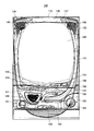
図1は本発明を適用した遊技機100の正面図であり、図2は遊技機100に備わる遊技盤1を示す正面図である。
遊技機100の前面枠120は本体枠(外枠)110にヒンジ130をして開閉回動可能に組み付けられる。遊技盤1(図2参照)は前面枠120の表側に形成された収納部(図示省略)に収装される。また、前面枠120には、遊技盤1の前面を覆うカバーガラス(透明部材)を備えたガラス枠140が取り付けられている。
FIG. 1 is a front view of a
A
ガラス枠140のカバーガラスの周囲には、装飾光が発光される装飾部材141が備えられている。この装飾部材141の内部には各種LED基板44が備えられている。この各種LED基板44のLED(発光体)を所定の発光態様によって発光することによって、装飾部材141が所定の発光態様によって発光する。
A
ガラス枠140の左右には、音響(例えば、効果音)を発する音出力手段としてのスピーカ145が備えられており、スピーカ145は、可聴帯域の音はもちろんのこと非可聴帯域の音を出力可能となっている。
ここで、非可聴帯域の音とは、人間の耳で聴き取れる周波数の範囲の上限を超える周波の音のことである。具体的には、人間の耳で聴き取れる周波数帯域はおおよそ20Hz〜20kHzと言われているので、20kHzを超える周波数帯域の音である。
Here, the sound of the non-audible band is a sound having a frequency exceeding the upper limit of the frequency range that can be heard by the human ear. Specifically, since it is said that the frequency band that can be heard by human ears is approximately 20 Hz to 20 kHz, it is a sound in a frequency band exceeding 20 kHz.
また、ガラス枠140の上部左右に備えられた各スピーカ145の後方には、各スピーカ145から出力された非可聴帯域の音を検出可能な音センサ148(図4参照)が配設されている。また、上皿151の下側にも、スピーカ145が備えられており、当該スピーカ145の後方にも音センサ148(図4参照)が配設されている。すなわち、スピーカ145の後方に音センサ148を配設することにより、スピーカ145の前方へ伝わる音波(正相)とは逆相の音波を検出できるようにされている。
ここで、音センサ148は、音出力手段としてのスピーカ145から出力された非可聴領域の音を検出する非可聴音検出手段として機能する。なお、音センサ148は、例えば非可聴帯域の音を検出可能なマイクであってもよい。
In addition, sound sensors 148 (see FIG. 4) capable of detecting sounds in inaudible bands output from the
Here, the
ガラス枠140の上方には照明ユニット146が備えられている。照明ユニット146の内部には、LED基板44が備えられている。
An
照明ユニット146の右側には、遊技機100のエラー発生や前面枠120の開放をホール店員に通知するためのエラー報知LED147が備えられている。
On the right side of the
前面枠120の下部の開閉パネル150には図示しない打球発射装置に遊技球を供給する上皿151が、固定パネル160には灰皿161、下皿162及び打球発射装置の操作部163等が備えられている。下皿162には、下皿162に貯まった遊技球を排出するための下皿球抜き機構164が備えられる。前面枠120下部右側には、ガラス枠140を施錠するための鍵125が備えられている。
The open /
また、遊技者が操作部163を回動操作することによって、打球発射装置は、上皿151から供給される遊技球を発射する。
Further, when the player rotates the
また、上皿151の上縁部には、遊技者からの操作入力を受け付けるためのセレクトボタン152及び演出ボタン153が備えられている。
The upper edge of the
遊技者がセレクトボタン152を操作することによって、表示装置43(図2参照)における変動表示ゲームの演出内容を選択することができる。また、遊技者が演出ボタン153を操作することによって、表示装置43における変動表示ゲームに、遊技者の操作を介入させた演出を行うことができる。
When the player operates the
上皿151の右上部には、遊技者が遊技球を借りる場合に操作する球貸ボタン154、及び、カードユニット(図示略)からプリペイドカードを排出させるために操作される排出ボタン155が設けられている。これらの球貸ボタン154、排出ボタン155の間には、プリペイドカードの残高を表示する残高表示部156が設けられる。
The upper right portion of the
図2に示すように、遊技機100は、内部の遊技領域1a内に遊技球を発射して(弾球して)遊技を行うもので、その前側上半部のガラス板の奥側には、遊技領域1aを構成する遊技盤1が設置されている。
As shown in FIG. 2, the
遊技盤1は、各種部材の取付ベースとなる平板状の遊技盤本体1b(木製もしくは合成樹脂製)を備え、該遊技盤本体1bの前面にガイドレール2で囲まれた遊技領域1aを有している。また、遊技盤本体1bの前面であってガイドレール2の外側には、前面構成部材3,3,…が取り付けられている。そして、このガイドレール2で囲まれた遊技領域1a内に発射装置から遊技球(打球;遊技媒体)を発射して遊技を行うようになっている。
The
遊技領域1aの略中央には、飾り特図変動表示ゲームの表示領域となる窓部22を形成するセンターケース20が取り付けられている。このセンターケース20に形成された窓部22の後方には、複数の識別情報を変動表示する変動表示ゲームを実行可能な可変表示手段としての表示装置43が配されるようになっている。この表示装置43は、例えば、液晶ディスプレイを備え、表示内容が変化可能な表示部43aがセンターケース20の窓部22を介して遊技盤1の前面側から視認可能となるように配されている。なお、表示装置43は、液晶ディスプレイを備えるものに限らず、EL、CRT等のディスプレイを備えるものであっても良い。
At the approximate center of the
また、遊技領域1a内には、普図始動ゲート4が設けられており、遊技球が普図始動ゲート4を通過した場合は、普図変動表示ゲームが実行されるようになっている。また、遊技領域1a内には、第1の始動入賞領域をなす第1始動入賞口13と、第2の始動入賞領域をなす普通変動入賞装置7と、が設けられている。そして、遊技球が第1始動入賞口13に入賞した場合は、補助遊技として第1特図変動表示ゲームが実行され、遊技球が普通変動入賞装置7に入賞した場合は、補助遊技として第2特図変動表示ゲームが実行されるようになっている。
In addition, a
普図始動ゲート4内には、該普図始動ゲート4を通過した遊技球を検出するためのゲートSW4a(図3参照)が設けられている。そして、遊技領域1a内に打ち込まれた遊技球が普図始動ゲート4内を通過すると、普図変動表示ゲームが行われる。また、普図変動表示ゲームを開始できない状態、例えば、既に普図変動表示ゲームが行われ、その普図変動表示ゲームが終了していない状態や、普図変動表示ゲームが当って普通変動入賞装置7が開状態に変換されている場合に、普図始動ゲート4を遊技球が通過すると、普図始動記憶数の上限数未満でならば、普図始動記憶数が1加算されて普図始動記憶が1つ記憶されることとなる。なお、普図変動表示ゲームの始動記憶は、LEDを備える普図記憶表示器15(図3参照)にて表示されるようになっている。
A gate SW4a (see FIG. 3) for detecting a game ball that has passed through the general diagram start
普図(普通図柄)変動表示ゲームは、状態表示器17を構成する普図表示器5(図3参照)で実行されるようになっている。なお、表示装置43の表示領域の一部で普図変動表示ゲームを表示するようにしても良く、この場合は識別図柄として、例えば、数字、記号、キャラクタ図柄などを用い、これを所定時間変動表示させた後、停止表示させることにより行うようにする。この普図変動表示ゲームの停止表示が特別の結果態様となれば、普図の当りとなって、普通変動入賞装置7の開閉部材7a,7aが所定時間(例えば、0.5秒間)開放される。これにより、普通変動入賞装置7に遊技球が入賞しやすくなり、第2特図変動表示ゲームの始動が容易となる。
The general-purpose (ordinary symbol) variation display game is executed by the general-purpose display 5 (see FIG. 3) constituting the
第1始動入賞口13の内部には第1特図始動口SW13d(図3参照)が備えられ、この第1特図始動口SW13dによって遊技球を検出することに基づき、補助遊技としての第1特図変動表示ゲームを開始する始動権利が発生するようになっている。また、普通変動入賞装置7の内部には第2特図始動口SW7d(図3参照)が備えられ、この第2特図始動口SW7dによって遊技球を検出することに基づき、補助遊技としての第2特図変動表示ゲームを開始する始動権利が発生するようになっている。この第1特図変動表示ゲームを開始する始動権利は、所定の上限数(例えば4)の範囲内で第1始動記憶として記憶される。そして、この第1始動記憶は、第1特図記憶表示器18(図3参照)に表示される。また、第2特図変動表示ゲームを開始する始動権利は、所定の上限数(例えば4)の範囲内で第2始動記憶として記憶される。そして、この第2始動記憶は、第2特図記憶表示器19(図3参照)にて表示される。
A first special figure start port SW13d (see FIG. 3) is provided inside the first
普通変動入賞装置7は左右一対の開閉部材7a,7aを具備し、第1始動入賞口13の下部に配設され、この開閉部材7a,7aは、常時は遊技球の直径程度の間隔をおいて閉じた状態、すなわち、遊技球が入賞し難い入賞困難状態(遊技者にとって不利な状態)を保持しているが、普図変動表示ゲームの結果が所定の停止表示態様となった場合には、ソレノイド(普電SOL7b、図3参照)によって、逆「ハ」の字状に開いて普通変動入賞装置7に遊技球が流入し易い入賞容易状態(遊技者にとって有利な状態)に変化させられるようになっている。
The normal
補助遊技としての第1特図変動表示ゲーム、第2特図変動表示ゲームは、状態表示器17を構成する第1特図表示器8、第2特図表示器9で実行されるようになっており、複数の識別情報を変動表示したのち、所定の結果態様を停止表示することで行われる。また、表示装置43にて各特図変動表示ゲームに対応して複数種類の識別情報(例えば、数字、記号、キャラクタ図柄など)を変動表示させる飾り特図変動表示ゲームが実行されるようになっている。そして、この特図変動表示ゲームの結果として、第1特図表示器8もしくは第2特図表示器9の表示態様が特別結果態様(たとえば「7」)となった場合には、大当りとなって特別遊技状態(いわゆる、大当り状態)となる。また、これに対応して表示装置43の表示態様も特別結果態様(例えば、「7,7,7」等のゾロ目数字の何れか)となる。なお、第1特図表示器8、第2特図表示器9は、別々の表示器でも良いし同一の表示器ででも良いが、各々独立して特図変動表示ゲームが表示される。また、表示装置43も、第1特図変動表示ゲームと第2特図変動表示ゲームとで別々の表示装置や別々の表示領域を使用するとしても良いし、同一の表示装置や表示領域を使用するとしても良いが、各々独立して飾り特図変動表示ゲームが表示される。また、遊技機に第1特図表示器8、第2特図表示器9を備えずに、表示装置43のみで特図変動表示ゲームを実行するようにしても良い。
The first special figure fluctuation display game and the second special figure fluctuation display game as the auxiliary game are executed by the first
そして、第1特図変動表示ゲームもしくは第2特図変動表示ゲームが開始可能な状態で、且つ、第1始動記憶数及び第2始動記憶数が0の状態で、例えば、第1始動入賞口13に遊技球が入賞すると、始動権利の発生に伴って第1始動記憶が記憶されて、第1始動記憶数が1加算されるととともに、直ちに第1始動記憶に基づいて、第1特図変動表示ゲームが開始され、この際に第1始動記憶数が1減算される。また、第1特図変動表示ゲームもしくは第2特図変動表示ゲームが開始可能な状態で、且つ、第1始動記憶数及び第2始動記憶数が0の状態で、例えば、普通変動入賞装置7に遊技球が入賞すると、始動権利の発生に伴って第2始動記憶が記憶されて、第2始動記憶数が1加算されるととともに、直ちに第2始動記憶に基づいて、第2特図変動表示ゲームが開始され、この際に第2始動記憶数が1減算される。
Then, in a state where the first special figure fluctuation display game or the second special figure fluctuation display game can be started and the first start memory number and the second start memory number are 0, for example, the first start prize opening When the game ball wins in 13, the first start memory is stored with the generation of the start right, the first start memory number is incremented by 1, and the first special figure is immediately based on the first start memory. The variable display game is started, and at this time, the first start memory number is decremented by one. Further, in a state where the first special figure fluctuation display game or the second special figure fluctuation display game can be started and the first start memory number and the second start memory number are 0, for example, the normal
一方、第1特図変動表示ゲームもしくは第2特図変動表示ゲームが直ちに開始できない状態、例えば、既に第1特図変動表示ゲームもしくは第2特図変動表示ゲームが行われ、その特図変動表示ゲームが終了していない状態や、特別遊技状態となっている場合に、第1始動入賞口13に遊技球が入賞すると、第1始動記憶数が上限数未満(例えば、4個未満)ならば、第1始動記憶数が1加算されて第1始動記憶が1つ記憶されることになる。同様に、この場合に普通変動入賞装置7に遊技球が入賞すると、第2始動記憶数が上限数未満(例えば、4個未満)ならば、第2始動記憶数が1加算されて第2始動記憶が1つ記憶されることになる。
On the other hand, a state in which the first special figure fluctuation display game or the second special figure fluctuation display game cannot be started immediately, for example, the first special figure fluctuation display game or the second special figure fluctuation display game has already been performed, and the special figure fluctuation display. If a game ball is won in the first
そして、第1特図変動表示ゲームもしくは第2特図変動表示ゲームが開始可能な状態となると、第1始動記憶もしくは第2始動記憶に基づき第1特図変動表示ゲームもしくは第2特図変動表示ゲームが開始される。このとき、第1特図変動表示ゲームと第2特図変動表示ゲームは同時に実行されることはなく、第2特図変動表示ゲームが第1特図変動表示ゲームよりも優先して実行されるようになっている。すなわち、第1始動記憶と第2始動記憶がある場合であって、特図変動表示ゲームの実行が可能となった場合は、第2特図変動表示ゲームが実行されるようになっている。 When the first special figure fluctuation display game or the second special figure fluctuation display game is ready to start, the first special figure fluctuation display game or the second special figure fluctuation display is based on the first start memory or the second start memory. The game starts. At this time, the first special figure fluctuation display game and the second special figure fluctuation display game are not executed simultaneously, and the second special figure fluctuation display game is executed with priority over the first special figure fluctuation display game. It is like that. That is, when there is a first start memory and a second start memory, and when the special figure fluctuation display game can be executed, the second special figure fluctuation display game is executed.
また、遊技領域1aには、上端側が手前側に倒れる方向に回動して開放可能になっているアタッカ形式の開閉扉10aを有し、第1特図変動表示ゲーム、第2特図変動表示ゲームの結果如何によって大入賞口を閉じた状態(遊技者にとって不利な状態)から開放状態(遊技者にとって有利な状態)に変換する特別変動入賞装置10、入賞口などに入賞しなかった遊技球を回収するアウト穴11が設けられている。この他、遊技領域1aには、一般入賞口12,12,…、打球方向変換部材としての風車14、多数の障害釘(図示略)などが配設されている。
In addition, the
特別変動入賞装置10は、上端側が手前側に倒れる方向に回動して開放可能になっているアタッカ形式の開閉扉10aによって開閉される大入賞口を備えていて、特別遊技状態中は、大入賞口を閉じた状態から開いた状態に変換することにより大入賞口内への遊技球の流入を容易にさせ、遊技者に所定の遊技価値(賞球)を付与するようになっている。なお、開閉扉10aは、例えば、駆動装置としてのソレノイド(大入賞口SOL10b、図3参照)により駆動される。また、大入賞口の内部(入賞領域)には、該大入賞口に入った遊技球を検出するカウントSW10c(図3参照)が配設されている。
The special variable winning
また、遊技領域1aに設けられた各一般入賞口12には、一般入賞口12に入った遊技球を検出するための入賞口SW12a(図3参照)が配設されている。そして、遊技を開始することにより遊技領域1a内に打ち込まれた遊技球が、一般入賞口12,12,…、普通変動入賞装置7、第1始動入賞口13、特別変動入賞装置10等の入賞口の何れかに入賞すると、それぞれの入賞口に対応した所定数の賞球が払出制御装置170(図3参照)によって払い出されるようになっている。払出制御装置170は、遊技制御装置30の制御の下で制御され所定数の賞球が払い出されるようにする。
In addition, in each general winning
また、センターケース20の上端部には、普図変動表示ゲーム、第1特図変動表示ゲーム、及び、第2特図変動表示ゲームの遊技状態を報知する状態表示器17が配設されている。
In addition, a
また、センターケース20は、表示部43aを囲うようにして、その周囲に変動表示ゲームの演出を装飾する装飾部24が備えられている。より具体的には、装飾部24は、変動表示ゲームに基づいて所定の演出動作を行う演出動作役物50と、当該所定の演出動作において補助的な演出を行う補助演出役物51と、を備えている。
In addition, the
演出動作役物50は、センターケース20の上部中央に備えられており、役物駆動モータ42(図3参照)の駆動力によって、当該演出動作役物50は表示部43aの前面を覆うように下方に移動するようになっている。
The
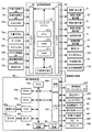
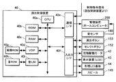
図3は、遊技機100の制御系の一部を示すブロック図である。図3に示すように、遊技機100は、その制御系として遊技の進行を制御するメイン制御装置としての遊技制御装置30、この遊技制御装置30の制御下で各種の演出に関する制御を行うサブ制御装置としての演出制御装置40とを備えている。
FIG. 3 is a block diagram showing a part of the control system of the
遊技制御装置30は、CPU31aやROM31b、RAM31cなどを備える遊技用ワンチップマイコン31を備えるとともに、入力インタフェース(入力I/F)32、出力インタフェース(出力I/F)33、外部通信端子34等により構成されている。
The
遊技用ワンチップマイコン31は、内部のCPU31aが制御部、演算部を備え、演算制御を行う他、各特図変動表示ゲームの大当り判定用乱数値などの各種乱数値なども生成している。
In the gaming one-
遊技用ワンチップマイコン31の内部のRAM31cには、第1始動入賞口13に設けられた第1特図始動口SW13d、普通変動入賞装置7に設けられた第2特図始動口SW7dのオン信号などを記憶する記憶領域や、前記各種乱数値の記憶領域、並びに、CPU31aの作業領域等を備えている。即ち、RAM31cには、CPU31aにより検出された遊技球の入賞が始動入賞として記憶されるようになっている。
In the
遊技用ワンチップマイコン31の内部のROM31bには、遊技上の制御プログラムや制御データが書き込まれている他、上述の各種乱数値に対応して、各特図変動表示ゲームの大当り発生を判定するための、特図変動表示ゲームの大当り判定値、変動パターン、リーチパターン(リーチアクションの種類)の判定値や連続予告演出の実行を決定する判定値などが記憶されている。
A game control program and control data are written in the
また、入力インタフェース32には、ローパスフィルタ及びバッファーゲートを介して、第1特図始動口SW13d、第2特図始動口SW7d、入賞口SW12a,…、ゲートSW4a、カウントSW10c、ガラス枠開放SW146、遊技機枠開放SW121、球切れSW122、などが接続されている。そして、入力インタフェース32は、これらから入力された各種信号を中継し、遊技用ワンチップマイコン31に対し出力する。なお、ガラス枠開放SW146は、ガラス枠140が開放されていることを検出するものであり、遊技機枠開放SW121は、前面枠120が開放されていることを検出するものである。また、球切れSW122は、島設備から供給された遊技球を払出制御装置170に誘導するシュートに設けられ、シュート内の遊技球がなくなったことを検出するものである。
Further, the input interface 32 is connected to a first special figure starting port SW13d, a second special figure starting port SW7d, a winning port SW12a,..., A gate SW4a, a count SW10c, a glass frame opening SW146, through a low-pass filter and a buffer gate. A gaming machine
また、出力インタフェース33には、遊技用ワンチップマイコン31から出力される各種の制御信号が入力される。これら制御信号は、該出力インタフェース33により中継されて、図示しない出力ポート及びドライバを介して、第1特図表示器8、第1特図記憶表示器18、第2特図表示器9、第2特図記憶表示器19、普図表示器5、普図記憶表示器15、普電SOL7b、大入賞口SOL10b、外部端子板16、払出制御装置170、演出制御装置40に出力される。
In addition, various control signals output from the gaming one-
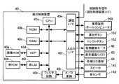
演出制御装置40は、演算処理用CPU40a、ROM40b、RAM40c及びVDP(Video Display Processor)40d等を備えるとともに、通信インタフェース(通信I/F)40e、入出力インタフェース(入出力I/F)40fを備えている。また、画像や映像データが記憶された画像ROM40g、音声データが記憶された音ROM40h、音の出力を制御する音制御手段としての音LSI40iや、音センサ148から入力されたアナログの音信号をデジタルの音信号に変換するA/D変換回路40j、デジタルに変換された音信号のうち可聴帯域の音信号をフィルタリングして非可聴帯域の音を出力するフィルタ回路40kを備えている。
The
この演出制御装置40は、通信インタフェース40eを介して遊技制御装置30から受信した各種信号(演出制御データ(各種コマンドなど))に基づいて(遊技制御装置30の制御の下に)遊技の演出の制御を行うものである。また、演出制御装置40は、通信インタフェース40eを介して管理装置200(ホールコンピュータ)接続されており、演出制御装置40から管理装置200に遊技機100の出球数等遊技に関する各種遊技情報や、遊技機100において生じたエラーに関する各異常情報を送信する。
This
入出力インタフェース40fには、遊技機100の前面に設けられたセレクトボタン152や演出ボタン153からの検出信号が入力されるようになっており、演出制御装置40は、この検出信号に基づき(遊技制御装置30の制御の下に)遊技の演出の制御を行うようになっている。
Detection signals from a
また、入出力インタフェース40fには、CPU40aから出力される各種の制御信号が入力され、これら制御信号は、該入出力インタフェース40fにより中継されて、図示しない出力ポート及びドライバを介して役物駆動モータ42、遊技盤1や該遊技盤1の前方を覆うガラス枠140に設けられた装飾用のLEDを備える各種LED基板44などに出力され、遊技の演出が行われるようになっている。なお、CPU40aから出力される制御信号のうち、画像の制御に関する制御信号は、CPU40aからVDP40dに出力され、VDP40dから該制御信号に基づく画像データが表示装置43に出力される。また、音声の制御に関する制御信号は、CPU40aから音LSI40iに出力され、音LSI40iから該制御信号に基づく音声データがスピーカ145に出力される。また、遊技機100に電源投入されている間、音LSI40iから非可聴帯域の音信号がスピーカ145に出力される。
Further, various control signals output from the
〔サウンド制御処理〕
次に、演出制御装置40によるサウンド制御処理について説明する。図5は、サウンド制御処理を説明するためのフローチャートである。
[Sound control processing]
Next, sound control processing by the
サウンド制御処理では、はじめに遊技制御装置30から所定のコマンドを受信することにより検査用の音を出力するためのテストモード音声処理を行う(ステップS1)。次に、遊技制御装置30から異常発生の報知を指令するエラーコマンドを受信した場合や、演出制御装置40と接続されている音センサ148から非可聴帯域の音信号を検出しない場合、その他各種センサ(例えば、磁気センサ(図示略)、振動センサ(図示略))からの所定の信号を検出することにより、各々のエラーに対応する音を設定するためのエラー報知処理を行う(ステップS2)。エラーコマンドは、エラー発生時に遊技制御装置30から出力されるコマンドであり、エラーとしては、例えば、遊技球の払い出しの際に、払い出し検出センサ(図示略)に検出された遊技球の数が所定の払い出し数に至らなかった場合や、遊技機枠開放スイッチ121、ガラス枠開放スイッチ146などによって不正な行為が検出された場合などがある。
In the sound control process, first, a test mode sound process for outputting a test sound by receiving a predetermined command from the
次に、遊技機100の遊技状態に対応する演出音を出力するためのサウンド設定処理を行い(ステップS3)、遊技者による演出ボタン153等の操作がなされたことを知らせるプッシュ音等を出力するためのイベントサウンド設定処理を行う(ステップS4)。そして、上記各処理(ステップS1〜S4)にて設定された音を出力する指令信号を音LSI40iに送信する送信処理(ステップS5)を行い、サウンド制御処理を終了する。
Next, a sound setting process for outputting a production sound corresponding to the gaming state of the
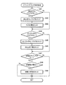
〔サウンド設定処理〕
次に、サウンド設定処理について説明する。図6はサウンド設定処理を説明するためのフローチャートである。
[Sound setting processing]
Next, the sound setting process will be described. FIG. 6 is a flowchart for explaining the sound setting process.
サウンド設定処理では、はじめに遊技機100に対して電源投入されたか否かの判定を行う(ステップS11)。
ここで、電源投入されると(ステップS11;Yes)、電源投入されている間、スピーカ145に対して不正がなされているか否かを検査するためのスピーカ検査音を出力するループ設定処理(ステップS12)を行う。
具体的には、図8(a)に示すように、電源投入されている間、人間が聴き取ることができない非可聴帯域の音(例えば20kHzを超える音)を2秒間隔毎に出力する設定を行う。
In the sound setting process, it is first determined whether or not the
Here, when the power is turned on (step S11; Yes), while the power is turned on, a loop setting process for outputting a speaker inspection sound for inspecting whether the
Specifically, as shown in FIG. 8 (a), a setting is made to output sounds in a non-audible band (for example, sounds exceeding 20 kHz) that cannot be heard by humans every 2 seconds while the power is turned on. I do.
そして、電源投入されたことを報知する電源投入音の出力を設定する処理を行う(ステップS13)。
一方、電源投入されたと判定されない場合(ステップS11;No)は、ステップS12及びS13をスキップして、ステップS14に移行する。
And the process which sets the output of the power-on sound which alert | reports that the power was turned on is performed (step S13).
On the other hand, when it is not determined that the power has been turned on (step S11; No), steps S12 and S13 are skipped and the process proceeds to step S14.
次に、遊技機100が停電復旧された状態であるか否かの判定を行う(ステップS14)。
ここで、遊技機100が停電普及された状態であると判定された場合(ステップS14;Yes)、停電復旧フラグをセットする処理(ステップS15)を行う。
一方、遊技機100が停電普及された状態でないと判定された場合(ステップS14;No)、ステップS15をスキップしてステップS16に移行する。
Next, it is determined whether or not the
Here, when it is determined that the
On the other hand, when it is determined that the
次に、遊技機100の遊技状態が客待ち状態であるか否かの判定を行う(ステップS16)。
ここで、遊技機100の遊技状態が客待ち状態であると判定された場合(ステップS16;Yes)、客待ちデモ音を設定する処理(ステップS17)を行う。
一方、遊技機100の遊技状態が客待ち状態でないと判定された場合(ステップS16;No)、ステップS17をスキップしてステップS18に移行する。
Next, it is determined whether or not the gaming state of the
Here, when it is determined that the gaming state of the
On the other hand, when it is determined that the gaming state of the
次に、遊技機100の遊技状態が特図変動表示ゲームにおいて識別図柄が変動中であるか否かの判定を行う(ステップS18)。
ここで、特図変動表示ゲームにおいて識別図柄が変動中であると判定された場合(ステップS18;Yes)、識別図柄が変動中であることを報知する変動音を設定する処理(ステップS19)を行う。
一方、特図変動表示ゲームにおいて識別図柄が変動中でないと判定された場合(ステップS18;No)、ステップS19をスキップしてステップS20に移行する。
Next, it is determined whether or not the identification state of the gaming state of the
Here, when it is determined that the identification symbol is fluctuating in the special symbol variation display game (step S18; Yes), a process of setting a fluctuating sound for notifying that the identification symbol is fluctuating (step S19) is performed. Do.
On the other hand, when it is determined that the identification symbol is not changing in the special figure changing display game (step S18; No), step S19 is skipped and the process proceeds to step S20.
次に、遊技機100の遊技状態が特図変動表示ゲームにおいて識別図柄が停止中であるか否かの判定を行う(ステップS20)。
ここで、特図変動表示ゲームにおいて識別図柄が停止中であると判定された場合(ステップS20;Yes)、識別図柄が停止中であることを報知する図柄停止音を設定する処理(ステップS21)を行う。
一方、特図変動表示ゲームにおいて識別図柄が停止中でないと判定された場合(ステップS20;No)、ステップS21をスキップしてステップS22に移行する。
Next, it is determined whether the gaming state of the
Here, when it is determined that the identification symbol is stopped in the special symbol variation display game (step S20; Yes), a process of setting a symbol stop sound for notifying that the identification symbol is stopped (step S21). I do.
On the other hand, when it is determined that the identification symbol is not stopped in the special figure variation display game (step S20; No), step S21 is skipped and the process proceeds to step S22.
次に、遊技機100の遊技状態がファンファーレ中であるか否かの判定を行う(ステップS22)。すなわち、遊技機100の遊技状態が特図変動表示ゲームにおいて特別遊技状態が発生したか否かを判定する。
ここで、遊技機100の遊技状態がファンファーレ中であると判定された場合(ステップS22;Yes)、特別遊技状態の発生を報知するファンファーレ音を設定する処理(ステップS23)を行う。
一方、遊技機100の遊技状態がファンファーレ中でないと判定された場合(ステップS22;No)、ステップS23をスキップしてステップS24に移行する。
Next, it is determined whether or not the gaming state of the
Here, when it is determined that the gaming state of the
On the other hand, when it is determined that the gaming state of the
次に、遊技機100の遊技状態が特別遊技状態のうち何れかのラウンド中であるか否かの判定を行う(ステップS24)。
ここで、遊技機100の遊技状態が特別遊技状態のうち何れかのラウンド中であると判定された場合(ステップS24;Yes)、かかるラウンドが1ラウンド目であるか否かの判定を行う(ステップS25)。
そして、1ラウンド目であると判定されると(ステップS25;Yes)、大当たり音をセットする処理(ステップS26)を行い、停電フラグをクリアする処理(ステップS27)を行う。
一方、1ラウンド目でないと判定されると(ステップS25;No)、ステップS26及びS27をスキップしてステップS28に移行する。
また、ステップS24において、遊技機100の遊技状態が特別遊技状態のうち何れのラウンド中でもないと判定された場合(ステップS24;No)、ステップS34へ移行する。
Next, it is determined whether or not the gaming state of the
Here, when it is determined that the gaming state of the
If it is determined that it is the first round (step S25; Yes), a process of setting a big hit sound (step S26) is performed, and a process of clearing the power failure flag is performed (step S27).
On the other hand, if it is determined that it is not the first round (step S25; No), steps S26 and S27 are skipped and the process proceeds to step S28.
If it is determined in step S24 that the gaming state of the
次に、特別遊技状態のラウンド数が15以上であるか否かの判定を行う(ステップS28)。
ここで、特別遊技状態のラウンド数が15以上であると判定されると(ステップS29;Yes)、大当たり音をループ設定する処理(ステップS29)を行い、停電フラグをクリアする処理(ステップS30)を行う。
一方、特別遊技状態のラウンド数が15以上でないと判定されると(ステップS28;No)、ステップS29及びS30をスキップしてステップS31に移行する。
Next, it is determined whether or not the number of rounds in the special game state is 15 or more (step S28).
Here, if it is determined that the number of rounds in the special gaming state is 15 or more (step S29; Yes), a process of setting a big hit sound as a loop (step S29) is performed, and a process of clearing the power failure flag (step S30). I do.
On the other hand, if it is determined that the number of rounds in the special gaming state is not 15 or more (step S28; No), steps S29 and S30 are skipped and the process proceeds to step S31.
次に、停電フラグが「オン」の状態であるか否かの判定を行う(ステップS31)。
ここで、停電フラグが「オン」の状態であると判定されると(ステップS31;Yes)、停電フラグをクリアする処理(ステップS32)を行い、大当たり音をセットする処理(ステップS33)を行う。
一方、停電フラグが「オン」の状態でないと判定されると(ステップS31;No)、ステップS32及びS33をスキップしてステップS34に移行する。
Next, it is determined whether or not the power failure flag is “ON” (step S31).
Here, if it is determined that the power failure flag is in the “on” state (step S31; Yes), processing for clearing the power failure flag (step S32) is performed, and processing for setting a big hit sound (step S33) is performed. .
On the other hand, if it is determined that the power failure flag is not in the “on” state (step S31; No), steps S32 and S33 are skipped and the process proceeds to step S34.
次に、エンディングフラグが「オン」の状態であるか否かの判定を行う(ステップS34)。
ここで、エンディングフラグが「オン」の状態であると判定されると(ステップS34;Yes)、エンディング音をセットする処理(ステップS35)を行い、サウンド設定処理を終了する。
一方、エンディングフラグが「オン」の状態でないと判定されると(ステップS34;No)、ステップS35をスキップしてサウンド設定処理を終了する。
Next, it is determined whether or not the ending flag is in an “on” state (step S34).
Here, if it is determined that the ending flag is in the “on” state (step S34; Yes), a process for setting the ending sound (step S35) is performed, and the sound setting process is terminated.
On the other hand, if it is determined that the ending flag is not in the “on” state (step S34; No), step S35 is skipped and the sound setting process is terminated.
これにより、演出制御装置40は、遊技者が認識可能な可聴領域の可聴領域音と遊技者が認識不可能な非可聴領域の非可聴領域音とを含む範囲内で予め設けられた複数の演出音の中から遊技機100の遊技状態に応じて演出音を設定する音設定手段として機能する。
Thereby, the
なお、スピーカ検査音のループ設定(ステップS12)は、遊技機100に対して電源投入されている間、一定間隔毎にスピーカ検査音を出力する設定に限らず、適宜スピーカ検査音の出力間隔及び出力回数を変更しても良い。
具体的には、例えば、図8(b)に示すように、所定のタイミングt1,t2で、スピーカ検査音の出力間隔を変更し、例えばタイミングt1で2sの周期T1から3sの周期T2に変更し、タイミングt2で3sの周期T2から1sの周期T3に変更する。このような制御は、ROM40bは乱数値と、スピーカ145による検査信号出力回数データ及び出力間隔データとを対応付けたデータテーブルを格納し、CPU40aは取得した乱数値を参照して当該データテーブルに応じたスピーカ検査音の出力回数及び出力間隔を設定する。そして、CPU40aは、設定されたスピーカ検査音の出力回数を消化するまでの間に新たに乱数値を取得して、次の周期におけるスピーカ検査音の出力回数及び出力間隔を設定することで行える。
より具体的には、図9に示すようなテーブルを参照して、電源投入された際にCPU40aが乱数値「0」〜「19」の何れかの値を取得した場合、1週目の周期T1において2秒間隔毎にスピーカ検査音を10回出力する設定を行う。次いで、2週目の周期T2の検査信号出力回数及び出力間隔の設定においてCPU40aが乱数値「20」〜「39」の何れかの値を取得した場合、3秒間隔毎にスピーカ検査音を5回出力する設定を行う。また同様に、3週目の周期T3の検査信号出力回数及び出力間隔の設定においてCPU40aが乱数値「40」〜「59」の何れかの値を取得した場合、1秒間隔毎にスピーカ検査音を15回出力する設定を行う(図8(b)参照)というように、CPU40aは、遊技機100に対して電源投入されている間、周期T1、T2、T3、…毎にスピーカ検査音の出力間隔を変更する。
これにより、演出制御装置40は、スピーカ145への不正を検出するためのスピーカ検査音の出力間隔及び出力回数を無作為に変更することができるので、不正に持ち込んだ音響装置によって、スピーカ検査音の出力間隔に合わせて当該スピーカ検査音の周波数と同じ帯域の音を出力させ、その間に目的とする不正行為を行うのを防止することができる。
Note that the speaker inspection sound loop setting (step S12) is not limited to the setting of outputting the speaker inspection sound at regular intervals while the
Specifically, for example, as shown in FIG. 8B, the output interval of the speaker inspection sound is changed at predetermined timings t1 and t2, and for example, the period T1 of 2s is changed to the period T2 of 3s at the timing t1. At the timing t2, the period is changed from the period T2 of 3s to the period T3 of 1s. In such a control, the
More specifically, referring to a table as shown in FIG. 9, when the
Thereby, the
〔イベントサウンド設定処理〕
次に、イベントサウンド設定処理について説明する。図7はイベントサウンド設定処理を説明するためのフローチャートである。
[Event sound setting processing]
Next, the event sound setting process will be described. FIG. 7 is a flowchart for explaining the event sound setting process.
イベントサウンド設定処理では、はじめに演出ボタン153が押圧されたことにより演出ボタンフラグが「オン」の状態であるか否かの判定を行う(ステップS41)。
ここで、演出ボタンフラグが「オン」の状態であると判定された場合(ステップS41;Yes)は、演出ボタンフラグをクリアする処理(ステップS42)を行い、演出ボタン153が押圧された際のPUSH音をセットする処理を行う(ステップS43)。
一方、演出ボタンフラグが「オン」の状態でないと判定された場合(ステップS41;No)は、ステップS42及びS43をスキップして、ステップS44に移行する。
In the event sound setting process, it is first determined whether or not the effect button flag is in the “on” state when the
Here, when it is determined that the effect button flag is in the “on” state (step S41; Yes), processing for clearing the effect button flag (step S42) is performed, and the
On the other hand, if it is determined that the effect button flag is not in the “on” state (step S41; No), steps S42 and S43 are skipped and the process proceeds to step S44.
次に、セレクトボタン152が押圧されたことによりセレクトボタンフラグが「オン」の状態であるか否かの判定を行う(ステップS44)。
ここで、セレクトボタンフラグが「オン」の状態であると判定された場合(ステップS44;Yes)は、セレクトボタンフラグをクリアする処理(ステップS45)を行い、セレクトボタン152が押圧された際のSELECT音をセットする処理を行う(ステップS46)。
一方、セレクトボタンフラグが「オン」の状態でないと判定された場合(ステップS44;No)は、ステップS45及びS46をスキップして、ステップS47に移行する。
Next, it is determined whether or not the select button flag is in the “on” state by pressing the select button 152 (step S44).
Here, when it is determined that the select button flag is in the “on” state (step S44; Yes), a process of clearing the select button flag (step S45) is performed, and when the
On the other hand, when it is determined that the select button flag is not in the “on” state (step S44; No), steps S45 and S46 are skipped and the process proceeds to step S47.
次に、特図1始動口SW(スイッチ)13dと特図2始動口SW(スイッチ)7dのうち少なくとも何れか一方が「オン」の状態であるか否かの判定を行う(ステップS47)。
ここで、特図1始動口SW(スイッチ)13dと特図2始動口SW(スイッチ)7dのうち少なくとも何れか一方が「オン」の状態であると判定された場合(ステップS47;Yes)は、「オン」の状態であると判定された始動口SWに係る遊技球の保留数(始動記憶数)が増加したか否かの判定を行う(ステップS48)。
そして、保留数(始動記憶数)が増加したと判定されると(ステップS48;Yes)、始動入賞音をセットする処理(ステップS49)を行い、イベントサウンド設定処理を終了する。
一方、保留数(始動記憶数)が増加していないと判定されると(ステップS48;No)、ステップS49をスキップして、イベントサウンド設定処理を終了する。
また、特図1始動口SW(スイッチ)13dと特図2始動口SW(スイッチ)7dの何れも「オン」の状態でないと判定された場合(ステップS47;No)は、ステップS48及びS49をスキップして、イベントサウンド設定処理を終了する。
Next, it is determined whether or not at least one of the special figure 1 start port SW (switch) 13d and the special figure 2 start port SW (switch) 7d is in an "on" state (step S47).
Here, when it is determined that at least one of the special figure 1 start port SW (switch) 13d and the special figure 2 start port SW (switch) 7d is in an “on” state (step S47; Yes). Then, it is determined whether or not the number of held game balls (starting memory number) related to the starting port SW determined to be in the “on” state has increased (step S48).
If it is determined that the number of holds (starting memory number) has increased (step S48; Yes), a process of setting a start winning sound (step S49) is performed, and the event sound setting process is terminated.
On the other hand, if it is determined that the number of holds (starting memory number) has not increased (step S48; No), step S49 is skipped and the event sound setting process is terminated.
Further, when it is determined that neither the special figure 1 start port SW (switch) 13d nor the special figure 2 start port SW (switch) 7d is in the “on” state (step S47; No), steps S48 and S49 are performed. Skip the event sound setting process.
次に、本実施形態におけるスピーカ145の異状判定及び音センサ148の異状判定の手法について、図10のタイミングチャートを参照して説明する。
演出制御装置40には、予めスピーカ検査音の周波数、出力回数及び出力間隔が設定されており、CPU40aは、音センサ148により検出されたスピーカ検査音の周波数、出力回数及び出力間隔それぞれの値が予め設定されたスピーカ検査音の周波数、出力回数及び出力間隔それぞれの値と同一であるか否かを判定する。
Next, the method for determining the abnormality of the
In the
まず、スピーカ145及び音センサ148が正常な場合について説明する。この場合、CPU40aの制御下において、スピーカ145からスピーカ検査音が出力(検査信号出力データ「ON」)されると、音センサ148はスピーカ検査音を検出(音センサ検出「ON」)し、CPU40aは、検出されたスピーカ検査音の周波数、出力回数及び出力間隔それぞれの値が予め設定されたスピーカ検査音の周波数、出力回数及び出力間隔それぞれの値と同一である場合、スピーカ145及び音センサ148がともに正常であると判定して、装飾部材141の各種LED基板44による装飾発光を有効な状態とする(図10のTaの期間)。
First, the case where the
次に、スピーカ145に異常が発生した場合について説明する。この場合、CPU40aの制御下において、スピーカ145からスピーカ検査音を出力するため検査信号出力データを「ON」にしても、スピーカ145からはスピーカ検査音が出力されず、音センサ148は予め設定された周波数、出力回数及び出力間隔のスピーカ検査音と同一のスピーカ検査音を検出しない(音センサ検出「OFF」)。このとき、CPU40aは、スピーカ145に異常があると判定して、スピーカ異常が発生したことを示すスピーカ異常情報を通信インタフェース40eを介して管理装置200に送信するとともに、表示装置43の表示及び装飾部材141の各種LED基板44による装飾発光を無効(消灯)の状態にする(図10のTbの期間)。
Next, a case where an abnormality has occurred in the
次に、音センサ148に異常が発生した場合について説明する。この場合、スピーカ145からスピーカ検査音を出力していない(検査信号出力データ「OFF」)にも関わらず、音センサ148においてスピーカ検査音を検出したとして音センサ検出信号の出力が「ON」になる。このとき、CPU40aは、音センサ148に異常があると判定して、音センサ異常が発生したことを示す音センサ異常情報を通信インタフェース40eを介して管理装置200に送信するとともに、表示装置43の表示及び装飾部材141の各種LED基板44による装飾発光を無効(消灯)の状態にする(図10のTcの期間)。
Next, a case where an abnormality has occurred in the
これにより、演出制御装置40は、音センサ148の検出結果に基づいてスピーカ145に異常が発生したか否かを判定する異常判定手段として機能し、スピーカ145からスピーカ検査音が出力された場合に音センサ148が当該スピーカ検査音を検出したか否かを判定するとともに、音センサ148がスピーカ検査音を検出した場合にスピーカ145から当該スピーカ検査音が出力されたか否かを判定する。
また、演出制御装置40は、異常が発生したと判定された場合に異常を示す異常情報を管理装置200に出力する異常情報出力手段として機能する。
また、演出制御装置40は、異常が発生したと判定された場合に、表示装置43の識別情報の可変表示を非表示にし、各種LED基板44のLEDを消灯状態にして、装飾制御を不能動化したこととなる。
Thereby, the
In addition, the
In addition, when it is determined that an abnormality has occurred, the
以上のように本実施形態の遊技機100によれば、音センサ148の検出結果に基づいてスピーカ145に異常が発生したか否かを判定し、異常が発生したと判定された場合に異常を示す異常情報を遊技機100の外部に接続された管理装置200に出力することができるので、スピーカ145に異常が発生して警告音の出力が不可能な状態となった場合でも、不正行為を適切に防止することができる。
また、非可聴帯域のスピーカ検査音によってスピーカ145に異常が発生したか否かの判定を行うようにしたので、遊技者に不快感を与えることなくスピーカ145の異常の有無を検出することができる。また、音によるスピーカの異常検出を行っていることを遊技者に悟られないようにすることができる。
As described above, according to the
Further, since it is determined whether or not an abnormality has occurred in the
また、演出制御装置40により異常が発生したと判定された場合には、表示装置43の可変表示を非表示にするとともに、各種LED基板44のLEDを消灯状態にして装飾制御を不能動化することができるので、不正行為により遊技機100に異常が発生したことが一見して直ぐに認識することができるようになり、不正行為による被害を好適に防止することができる。
また、演出制御装置40によって、音センサ148がスピーカ検査音を検出した場合にスピーカ145から当該スピーカ検査音が出力されたか否かを判定することができるので、音センサ148に異常が発生した場合でも、不正行為を適切に防止することができる。
また、スピーカの異常検出と音センサの異常検出の両方を行うことで、いずれか一方が故障した場合にもいち早く故障を検出することができる。
If the
Further, when the
Further, by performing both the abnormality detection of the speaker and the abnormality detection of the sound sensor, the failure can be detected promptly even when either one fails.
また、音センサ148をスピーカ145の後方に配置したので、音センサ148が、スピーカ145から出力した正位相の音の伝達を阻害する障害となることなく、遊技者に聞こえる音が割れたような音になったり、反射音との干渉で違和感のある音に変化してしまうのを防止することができ、遊技者は当該正位相の音を適切に認識することができる。
In addition, since the
〔変形例1〕
次に、本実施形態の遊技機100の変形例1について説明する。なお、基本的には、上述の遊技機100と同様の構成を有しており、以下、同様の構成を有する部分については同じ符号を付して説明を省略し、主に異なる部分について説明する。
変形例1の遊技機100は、管理装置200側で設定して送信したスピーカ検査音の出力周波数データを受信して、当該出力周波数データに従った周波数のスピーカ検査音をスピーカ145から出力するようにしたものである。
[Modification 1]
Next,
The
図11に示すように、管理装置200は、遊技機100の演出制御装置40と通信インタフェース40eを介して通信可能となっており、管理装置200から演出制御装置40に対してスピーカ検査音の周波数に係る出力周波数データを送信する。
具体的には、図13(a)に示すように、管理装置200は、当該管理装置200が備えるROM(図示略)に設定「A」〜「E」のそれぞれと対応付けられて20〜24kHzの複数のスピーカ検出音(非可聴音)の出力周波数データを格納している。
そして、例えば、図13(b)に示すように、管理装置200が備える表示装置の表示画面210を参照しながら、遊技店員による選択決定ボタン(図示略)の操作によって、遊技店に設置された複数の遊技機100,…,100それぞれに付された遊技台番号ごとにA〜Eの各文字のうち何れかの文字を選択決定することで、A〜Eの各文字と対応付けられて記憶されている出力周波数データをROMから読み出してスピーカ検査音(非可聴領域音)の出力周波数を設定して遊技台番号に対応した各遊技機100に出力周波数データを送信する。
As shown in FIG. 11, the
Specifically, as illustrated in FIG. 13A, the
Then, for example, as shown in FIG. 13B, the game shop clerk is installed in the game store by operating a selection decision button (not shown) while referring to the
次に、変形例1の遊技機100におけるサウンド設定処理(図6参照)について説明する。
演出制御装置40は、遊技機100に対して電源が投入されると(ステップS11;Yes)、管理装置200から送信された出力周波数データに対応した周波数のスピーカ検査音をループ設定(ステップS12)する。
具体的には、例えば、図13(b)に示すように、遊技台番号「001」の遊技機100に対して設定「A」が選択決定されている場合、管理装置200は「20kHz」の出力周波数データを遊技台番号「001」の遊技機100(演出制御装置40)に送信する。そして、演出制御装置40は、管理装置200から送信された出力周波数データに対応した「20kHz」のスピーカ検査音をループ設定(ステップS12)する。そして、上記実施形態と同様にステップS13以降の処理を行い、サウンド設定処理を終了する。
Next, a sound setting process (see FIG. 6) in the
When the power is turned on to the gaming machine 100 (step S11; Yes), the
Specifically, for example, as illustrated in FIG. 13B, when the setting “A” is selected and determined for the
これにより、演出制御装置40は、複数種類の異なる周波数のスピーカ検査音の中から何れか一のスピーカ検査音を設定可能であって、管理装置200から送信される出力周波数データ(非可聴音設定情報)に基づいて、当該一のスピーカ検査音を設定するようにし、設定された一のスピーカ検査音と同じ周波数のスピーカ検査音を検出したか否かに応じてスピーカ145に異常が発生したか否かを判定することとなる。
Thereby, the
このように変形例1の遊技機100によれば、管理装置200から送信される出力周波数データに基づいて、複数種類の異なる周波数のスピーカ検査音の中から何れか一のスピーカ検査音を設定し、当該一のスピーカ検査音と同じ周波数のスピーカ検査音を検出したか否かに応じてスピーカ145に異常が発生したか否かを判定することができるので、遊技店に設置される各遊技機100,…,100にそれぞれ異なる周波数のスピーカ検査音を設定可能となり、ある遊技機100が出力したスピーカ検査音によって他の遊技機100の演出制御装置40が誤判定してしまうことを適切に防止することができる。
As described above, according to the
なお、今回開示された実施の形態はすべての点で例示であって制限的なものではないと考えられるべきである。例えば、スピーカ145の異状判定処理及び音センサ148の異状判定処理を管理装置200で行うようにしても良い。
具体的には、図12に示すように、音センサ148を遊技機にそれぞれ設ける代わりに、管理装置200に音センサ148を設け、管理装置200は、遊技店に設置された複数の遊技機100,…,100それぞれに配設された各スピーカ145から出力されたアナログの音信号をデジタルの音信号に変換する。そして、変換されたデジタルの音信号のうち可聴帯域の音信号をフィルタリングして非可聴帯域の音を抽出することにより、上記実施形態の遊技機100と同様にして、スピーカ145の異状判定処理及び音センサ148の異状判定処理を行う。この場合にも、各遊技機100のスピーカ145が発する非可聴域の音の周波数を異ならせることで、いずれの遊技機で異常が発生しているか識別できるようになる。
The embodiment disclosed this time should be considered as illustrative in all points and not restrictive. For example, the abnormality determination process for the
Specifically, as shown in FIG. 12, instead of providing the
また、本実施形態の遊技機100では、サウンド設定処理(図6参照)にて、非可聴帯域の音であるスピーカ検査音をループ設定して、遊技機100に電源が投入されている間、演出制御装置40または管理装置200により設定された周波数のスピーカ検査音を出力するようにしたが、上記のように音センサ148が管理装置200に接続されている遊技設備(図12参照)では、例えば、遊技制御装置30から演出制御装置40へ各種制御コマンド(始動入賞コマンド、図柄停止コマンド等)が送信されるごとに、つまりリアルタイム制御で各種制御コマンドに応じた非可聴帯域の音を出力するようにしても良い。
具体的には、図14に示すように、演出制御装置40は、例えば、遊技制御装置30から始動入賞コマンドを受信した場合には、始動入賞したことを報知する始動入賞音とともに非可聴音A(20kHz)を出力する。また、演出制御装置40は、図柄停止コマンドを受信した場合には、識別図柄が停止したことを報知する停止音とともに非可聴音Aの周波数とは異なる非可聴音B(例えば、21kHz)を出力する。
Further, in the
Specifically, as shown in FIG. 14, for example, when the
これにより、管理装置200は、各種制御コマンドに応じた非可聴帯域の音を検出するだけで、スピーカ145の異常判定処理を行うとともに、遊技機100の遊技に関する遊技情報を受信することができるようになり、管理装置200の処理負担を軽減することができる。
As a result, the
さらに、上記したように各種制御コマンドに応じて不正検出のため非可聴帯域の音を発生するのみならず、例えば電話機のいわゆるトーン信号のように可聴帯域の中から幾つかの周波数を選択し、それらの周波数の組み合わせで各遊技機100の識別コードを表すように設定し、各遊技機100からトーン信号からなる識別コードと各遊技機100の大当りなどの情報を非可聴帯域の音で送信し、管理装置200が備える音センサ148でその情報を受信して認識するように構成しても良い。このような構成とすることにより、管理装置200と各遊技機100,…,100とを接続する信号線(配線やケーブル)を設けることなく、遊技機100からの情報を管理装置200へ伝達することが可能となる。
Furthermore, as described above, in addition to generating non-audible band sound for fraud detection according to various control commands, for example, select several frequencies from the audible band like a so-called tone signal of a telephone, The combination of these frequencies is set to represent the identification code of each
さらに、本発明の遊技機は、上記実施形態に示されるようなパチンコ遊技機に限定されるものではなく、例えば、その他のパチンコ遊技機、アレンジボール遊技機、雀球遊技機などの遊技機を使用する全ての遊技機に適用可能である。 Furthermore, the gaming machine of the present invention is not limited to the pachinko gaming machine as shown in the above embodiment, and for example, other pachinko gaming machines, arrange ball gaming machines, sparrow ball gaming machines, etc. Applicable to all used gaming machines.
100 遊技機
30 遊技制御装置
40 演出制御装置(音選択設定手段、音制御手段、異常判定手段、異常情報出力手段)
43 表示装置(可変表示手段)
145 スピーカ(音出力手段)
148 音センサ(非可聴音検出手段)
200 管理装置
100
43 Display device (variable display means)
145 Speaker (sound output means)
148 Sound sensor (non-audible sound detection means)
200 Management device
Claims (5)
音を出力可能な音出力手段と、を備え、
前記可変表示手段による表示結果が特定の表示態様となった場合に遊技者にとって有利な特別遊技状態に制御可能となる遊技機において、
遊技者が認識可能な可聴領域の可聴領域音と遊技者が認識不可能な非可聴領域の非可聴領域音とを含む範囲内で予め設定された複数の演出音の中から遊技機の遊技状態に応じていずれかの演出音を選択設定する音選択設定手段と、
前記音選択設定手段により選択設定された前記演出音を前記音出力手段から出力させる音制御手段と、
前記音制御手段による制御に基づいて前記音出力手段から出力された非可聴領域音を検出する非可聴音検出手段と、
前記非可聴音検出手段の検出結果に基づいて前記音出力手段に異常が発生したか否かを判定する異常判定手段と、
前記異常判定手段により異常が発生したと判定された場合に異常を示す異常情報を前記遊技機の外部に出力する異常情報出力手段と、
を備えたことを特徴とする遊技機。 Variable display means for variably displaying identification information;
Sound output means capable of outputting sound,
In the gaming machine that can be controlled to a special gaming state advantageous to the player when the display result by the variable display means becomes a specific display mode,
The gaming state of the gaming machine from a plurality of preset sounds set within a range including an audible sound in the audible area that can be recognized by the player and a non-audible sound in the non-audible area that cannot be recognized by the player Sound selection setting means for selecting and setting one of the production sounds according to
Sound control means for outputting the effect sound selected and set by the sound selection setting means from the sound output means;
A non-audible sound detecting means for detecting a non-audible area sound output from the sound output means based on control by the sound control means;
An abnormality determination means for determining whether an abnormality has occurred in the sound output means based on a detection result of the non-audible sound detection means;
Abnormality information output means for outputting abnormality information indicating an abnormality to the outside of the gaming machine when the abnormality determination means determines that an abnormality has occurred;
A gaming machine characterized by comprising:
前記異常判定手段は、
前記音出力手段から非可聴領域音が出力された場合に前記非可聴音検出手段が当該非可聴領域音を検出したか否かを判定する出力異常判定手段、
または、
前記非可聴音検出手段が非可聴領域音を検出した場合に前記音出力手段から当該非可聴領域音が出力されたか否かを判定する検出異常判定手段、
を含み、前記出力異常判定手段または検出異常判定手段により異常が発生したと判定された場合には、
前記可変表示手段は、前記識別情報の可変表示を非表示にし、
前記装飾制御手段は、前記発光体を消灯状態にして、前記装飾制御を不能動化するようにしたことを特徴とする請求項1に記載の遊技機。 With a decoration control means for performing decoration control of the light emitter provided in the gaming machine,
The abnormality determining means includes
An output abnormality determination means for determining whether or not the non-audible sound detection means has detected the non-audible area sound when a non-audible area sound is output from the sound output means;
Or
A detection abnormality determination means for determining whether or not the non-audible area sound is output from the sound output means when the non-audible sound detection means detects a non-audible area sound;
And when it is determined that an abnormality has occurred by the output abnormality determination means or the detection abnormality determination means,
The variable display means hides the variable display of the identification information,
The gaming machine according to claim 1, wherein the decoration control means turns off the light emitter to disable the decoration control.
複数種類の異なる周波数の非可聴領域音の中から何れか一の非可聴領域音を設定可能であって、遊技機の外部に設けられ当該遊技機を管理する管理装置から送信される非可聴音設定情報に基づいて、当該一の非可聴領域音を設定するようにし、
前記異常判定手段は、
前記音設定手段により設定された一の非可聴領域音と同じ周波数の非可聴領域音を検出したか否かに応じて前記音出力手段に異常が発生したか否かを判定することを特徴とする請求項3に記載の遊技機。 The sound setting means includes
Any one non-audible area sound of different types of non-audible area sounds can be set, and the non-audible sound transmitted from a management device that is provided outside the gaming machine and manages the gaming machine Based on the setting information, the one non-audible area sound is set,
The abnormality determining means includes
It is determined whether or not an abnormality has occurred in the sound output means according to whether or not a non-audible area sound having the same frequency as the one non-audible area sound set by the sound setting means is detected. The gaming machine according to claim 3.
前記非可聴音設定情報は、前記非可聴領域音の出力回数情報及び出力間隔情報を含み、
前記音設定手段は更に、
前記管理装置から送信される前記非可聴音設定情報に基づいて、非可聴領域音の出力回数及び出力間隔を設定可能とし、
前記異常判定手段は、
前記音設定手段により設定された非可聴領域音の出力回数及び出力間隔と同じ出力回数及び出力間隔の非可聴領域音を検出したか否かに応じて前記音出力手段に異常が発生したか否かを判定することを特徴とする請求項4に記載の遊技機。 The management device can specify the number of outputs and output interval of non-audible area sound,
The non-audible sound setting information includes output number information and output interval information of the non-audible area sound,
The sound setting means further includes
Based on the non-audible sound setting information transmitted from the management device, it is possible to set the number of outputs and output interval of non-audible area sound,
The abnormality determining means includes
Whether or not an abnormality has occurred in the sound output means depending on whether or not a non-audible area sound having the same output frequency and output interval as the output frequency and output interval of the non-audible area sound set by the sound setting means has been detected The game machine according to claim 4, wherein the game machine is determined.
Priority Applications (1)
| Application Number | Priority Date | Filing Date | Title |
|---|---|---|---|
| JP2009244088A JP2011087780A (en) | 2009-10-23 | 2009-10-23 | Game machine |
Applications Claiming Priority (1)
| Application Number | Priority Date | Filing Date | Title |
|---|---|---|---|
| JP2009244088A JP2011087780A (en) | 2009-10-23 | 2009-10-23 | Game machine |
Publications (2)
| Publication Number | Publication Date |
|---|---|
| JP2011087780A true JP2011087780A (en) | 2011-05-06 |
| JP2011087780A5 JP2011087780A5 (en) | 2012-11-15 |
Family
ID=44106642
Family Applications (1)
| Application Number | Title | Priority Date | Filing Date |
|---|---|---|---|
| JP2009244088A Pending JP2011087780A (en) | 2009-10-23 | 2009-10-23 | Game machine |
Country Status (1)
| Country | Link |
|---|---|
| JP (1) | JP2011087780A (en) |
Cited By (3)
| Publication number | Priority date | Publication date | Assignee | Title |
|---|---|---|---|---|
| JP2014212934A (en) * | 2013-04-25 | 2014-11-17 | 株式会社ユニバーサルエンターテインメント | Game system |
| JP2015062577A (en) * | 2013-09-25 | 2015-04-09 | タイヨーエレック株式会社 | Game machine |
| JP2015062578A (en) * | 2013-09-25 | 2015-04-09 | タイヨーエレック株式会社 | Game machine |
-
2009
- 2009-10-23 JP JP2009244088A patent/JP2011087780A/en active Pending
Cited By (3)
| Publication number | Priority date | Publication date | Assignee | Title |
|---|---|---|---|---|
| JP2014212934A (en) * | 2013-04-25 | 2014-11-17 | 株式会社ユニバーサルエンターテインメント | Game system |
| JP2015062577A (en) * | 2013-09-25 | 2015-04-09 | タイヨーエレック株式会社 | Game machine |
| JP2015062578A (en) * | 2013-09-25 | 2015-04-09 | タイヨーエレック株式会社 | Game machine |
Similar Documents
| Publication | Publication Date | Title |
|---|---|---|
| JP4643455B2 (en) | Game system | |
| JP4570100B2 (en) | Game machine | |
| JP7263143B2 (en) | game machine | |
| JP2001178941A (en) | Game machine with alarm function | |
| JP2014117454A (en) | Game machine | |
| JP2014008184A (en) | Game machine | |
| JP2008246120A (en) | Game machine | |
| JP2019103645A (en) | Game machine | |
| JP2008104681A (en) | Game machine | |
| JP2011087780A (en) | Game machine | |
| JP2019187900A (en) | Game machine | |
| JP2015171665A (en) | Game machine | |
| JP7248523B2 (en) | game machine | |
| JP7248519B2 (en) | game machine | |
| JP4667906B2 (en) | Game machine | |
| JP2000024172A (en) | Pattern combining game device, pattern combination controlling method and storage medium | |
| JP7248520B2 (en) | game machine | |
| JP2018149185A (en) | Game machine | |
| JP4219604B2 (en) | Game machine | |
| JP7263145B2 (en) | game machine | |
| JP2005103149A (en) | Game machine | |
| JP7263146B2 (en) | game machine | |
| JP7242503B2 (en) | game machine | |
| JP7242505B2 (en) | game machine | |
| JP7263144B2 (en) | game machine |
Legal Events
| Date | Code | Title | Description |
|---|---|---|---|
| A521 | Written amendment |
Free format text: JAPANESE INTERMEDIATE CODE: A523 Effective date: 20120926 |
|
| A621 | Written request for application examination |
Free format text: JAPANESE INTERMEDIATE CODE: A621 Effective date: 20120926 |
|
| RD02 | Notification of acceptance of power of attorney |
Free format text: JAPANESE INTERMEDIATE CODE: A7422 Effective date: 20120926 |
|
| A131 | Notification of reasons for refusal |
Free format text: JAPANESE INTERMEDIATE CODE: A131 Effective date: 20130820 |
|
| A02 | Decision of refusal |
Free format text: JAPANESE INTERMEDIATE CODE: A02 Effective date: 20131210 |