JP2010519476A - 上薬で被覆された化学反応装置のための貯留区域無し扁平台座付きで上方開口部を有する排出用集合体 - Google Patents
上薬で被覆された化学反応装置のための貯留区域無し扁平台座付きで上方開口部を有する排出用集合体 Download PDFInfo
- Publication number
- JP2010519476A JP2010519476A JP2009550303A JP2009550303A JP2010519476A JP 2010519476 A JP2010519476 A JP 2010519476A JP 2009550303 A JP2009550303 A JP 2009550303A JP 2009550303 A JP2009550303 A JP 2009550303A JP 2010519476 A JP2010519476 A JP 2010519476A
- Authority
- JP
- Japan
- Prior art keywords
- discharge assembly
- discharge
- conical
- assembly according
- sealing
- Prior art date
- Legal status (The legal status is an assumption and is not a legal conclusion. Google has not performed a legal analysis and makes no representation as to the accuracy of the status listed.)
- Granted
Links
Images


Classifications
-
- F—MECHANICAL ENGINEERING; LIGHTING; HEATING; WEAPONS; BLASTING
- F16—ENGINEERING ELEMENTS AND UNITS; GENERAL MEASURES FOR PRODUCING AND MAINTAINING EFFECTIVE FUNCTIONING OF MACHINES OR INSTALLATIONS; THERMAL INSULATION IN GENERAL
- F16K—VALVES; TAPS; COCKS; ACTUATING-FLOATS; DEVICES FOR VENTING OR AERATING
- F16K1/00—Lift valves or globe valves, i.e. cut-off apparatus with closure members having at least a component of their opening and closing motion perpendicular to the closing faces
- F16K1/32—Details
- F16K1/34—Cutting-off parts, e.g. valve members, seats
- F16K1/36—Valve members
- F16K1/38—Valve members of conical shape
-
- F—MECHANICAL ENGINEERING; LIGHTING; HEATING; WEAPONS; BLASTING
- F16—ENGINEERING ELEMENTS AND UNITS; GENERAL MEASURES FOR PRODUCING AND MAINTAINING EFFECTIVE FUNCTIONING OF MACHINES OR INSTALLATIONS; THERMAL INSULATION IN GENERAL
- F16K—VALVES; TAPS; COCKS; ACTUATING-FLOATS; DEVICES FOR VENTING OR AERATING
- F16K27/00—Construction of housing; Use of materials therefor
- F16K27/07—Construction of housing; Use of materials therefor of cutting-off parts of tanks, e.g. tank-cars
-
- F—MECHANICAL ENGINEERING; LIGHTING; HEATING; WEAPONS; BLASTING
- F16—ENGINEERING ELEMENTS AND UNITS; GENERAL MEASURES FOR PRODUCING AND MAINTAINING EFFECTIVE FUNCTIONING OF MACHINES OR INSTALLATIONS; THERMAL INSULATION IN GENERAL
- F16K—VALVES; TAPS; COCKS; ACTUATING-FLOATS; DEVICES FOR VENTING OR AERATING
- F16K51/00—Other details not peculiar to particular types of valves or cut-off apparatus
-
- B—PERFORMING OPERATIONS; TRANSPORTING
- B01—PHYSICAL OR CHEMICAL PROCESSES OR APPARATUS IN GENERAL
- B01J—CHEMICAL OR PHYSICAL PROCESSES, e.g. CATALYSIS OR COLLOID CHEMISTRY; THEIR RELEVANT APPARATUS
- B01J2219/00—Chemical, physical or physico-chemical processes in general; Their relevant apparatus
- B01J2219/02—Apparatus characterised by their chemically-resistant properties
- B01J2219/0204—Apparatus characterised by their chemically-resistant properties comprising coatings on the surfaces in direct contact with the reactive components
- B01J2219/0213—Apparatus characterised by their chemically-resistant properties comprising coatings on the surfaces in direct contact with the reactive components of enamel
Landscapes
- Engineering & Computer Science (AREA)
- General Engineering & Computer Science (AREA)
- Mechanical Engineering (AREA)
- Lift Valve (AREA)
- Physical Or Chemical Processes And Apparatus (AREA)
- Indication Of The Valve Opening Or Closing Status (AREA)
Abstract
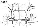
【解決手段】排出のための出口用孔部の下部に、扁平環状パッキン状の取り替え可能な台座用部材(11)が具えてあり、同部材の上方部分が、弁の頭部(10)の台座になり、完全流出用傾斜部になっている少なくとも1の切欠き部(21)を有する。本発明は、とりわけ釉薬被覆型化学反応装置の製造者と利用者に関わる。
【選択図】図1
Description
2. 孔部2
3. 排出用円筒形導管3
4. 排出用管状部4
5. 分厚いフランジの導管5
6. 出口の外方孔部6
7. 前額面7
8. 可動弁8
9. ロッド9
10. 頭部10
11. 台座11
12. 支承用部材12
13. 機械本体13
14. 排出室14
15. 側方主出口15
16. 技術用側方接触部16
17. 密閉案内17
18. パッキン箱18
19
20. 作動用装置20
21. 円錐形受容用面21
22. 支承用円錐形表面22
23. 円錐形肩部23
24. 円錐形傾斜部24
25. 開口部25
26. 温度センサー26
27. 外方環状骨組み27
28. 扁平パッキン28と29
29. 扁平パッキン
30. 金属製芯部30、31
31. 金属製芯部
32. 環状部材32
33. 中身のつまった部材33
34. 突出内方縁部34
35. 突出内方縁部35
36. 下方縁部36
37. のど部37
38. 紡炎冠状部38
39. 上方縁部39
40. 環状体40
41. 芯部41
Claims (19)
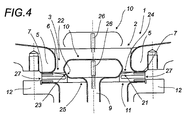
- 本体が、新品または既存の釉薬被覆の化学反応装置の出口用孔部の外方構造体(6)に取り付けておかれる、排出用集合体であり、反応装置の排出用すなわち空にするための可動要素を1回の動作で上方に開けられる頭部(10)付き弁(8)を含むゲート弁を内蔵しており、弁の頭部(10)は、台座用部材(11)上に密閉のために下方に向かって支承するために移動して出口用孔部(6)を閉鎖し、前額面(7)になる出口用孔部(6)の構造体の下面と、排出用集合体の本体の上面が扁平であり、および取り替え可能な台座用部材(11)の凹部状形状の少なくとも1の平面と密閉のために接触するために適応する形状を有する弁の頭部(10)の下方部分と、閉鎖状態において接触する中央切欠き部になっている、少なくとも1の傾斜部で、上方部分が、下方に向かって集中する凹部状の形状を有する排出用中央開口部(25)を有する扁平環状パッキンの形による密閉と完全流出のための取り替え可能な台座用部材(11)が、出口用孔部の構造体の前額面(7)と、排出用集合体の本体の上方部分との間の締めつけ用機械的集合による接近、取付けおよび締めつけによる密閉のための取付けと保持がなされ、このようにしてこの単一の唯一の取り替え可能な台座用部材(11)によって、完全な密閉状態の閉鎖と、化学反応装置の排出すなわち空にする時に、製品の沈着区域を生じないで完全流出の開放を可能にしていることを特徴としている排出用集合体。
- 取り替え可能な台座用部材(11)になる扁平環状パッキンが扁平な分厚いパッキンであることを特徴とする、請求項1による排出用集合体。
- 凹部を有する扁平パッキンの形状が、中央開口部に向かうその周縁の傾斜部が二重であり、第1の傾斜部が完全流出を確立するためであり、第2の傾斜部が密閉のための閉鎖を確立するためであることを特徴とする、請求項1または2による排出用集合体。
- 取り替え可能な台座用部材(11)の切欠き部が円錐形であることを特徴とする、請求項1、2または3のいずれか1の請求項による集合体。
- 取り替え可能な台座用部材(11)の円錐形切欠き部が、中央開口部(25)と同心円の連続的2の円錐形傾斜部を有する円錐形形状を有し、肩部になるその第1の傾斜部(23)が中央開口部(25)の内方を画定し、第2の傾斜部(24)が第1の傾斜部を同心円的に取り囲むことを特徴とする、前記請求項による集合体。
- 中央開口部(25)を内側で画定している第1の円錐形傾斜部(23)の傾斜度が第2の円錐形傾斜部(24)の傾斜度よりも大きいが、巾がもっと狭いことを特徴とする、前記請求項による集合体。
- 取り替え可能な台座用部材(11)の円錐形切欠き部の形状と、弁の頭部(10)の下方周縁部間の密閉のための接触区域が狭いことを特徴とする、前記請求項のいずれか1の請求項による集合体。
- 円錐形の二重傾斜部が、密閉のための接触で弁の頭部(10)の下方部分を受ける中央開口部(25)の上方縁部になる円錐形中央肩部(23)からなっており、この円錐形中央肩部(23)がもっとゆるい傾斜度の円錐形形状に同心円的に取り囲まれていて、完全流出用傾斜部を形成しているいことを特徴とする、請求項5による集合体。
- 台座兼完全流出用部材(11)が、内方環状骨組みを有することを特徴とする、請求項1による排出用集合体。
- 台座兼完全流出用部材(11)が、上方と下方の面のそれぞれに一つずつ、強化区域または周縁環状部材の形で、外方環状骨組み(27)を有することを特徴とする、請求項1または5による排出用集合体。
- 排出用集合体の部材(11)になる環状パッキンが、排出用集合体の本体(13)のフランジ状上方部分(12)によって、排出用外方孔部(6)の内側縁部に、密閉のために押しつけられることを特徴とする、請求項3による排出用集合体。
- 排出用集合体の弁の可動要素の頭部(10)が、円筒形部分によって、上方に延長されていることを特徴とする、請求項1による排出用集合体。
- 頭部(10)の上方部分が、温度センサー(23)を内蔵していることを特徴とする、請求項12による排出用集合体。
- 排出用集合体の弁の可動要素の頭部(10)が閉鎖状態にあるとき、円筒形状上方部分が、上方において、タンクの底部とほぼ同一レベルになる額部で終っていることを特徴とする、請求項11または12による排出用集合体。
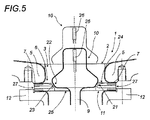
- 排出用集合体の弁の可動要素の頭部(10)がその基部に、円錐形面(22)を有しており、同円錐形面で、台座用部材(11)上に密閉のために来ることを特徴とする、請求項1による排出用集合体。
- 取り替え可能な台座用部材(11)が、火災の場合に、排出用要素の密閉性の維持期間を延ばすことを目的としている紡炎金属製周縁冠(38)を有することを特徴とする、請求項1による排出用集合体。
- 紡炎金属製周縁冠(38)が、肩部の縁部(39)で上方に向かって延びていることを特徴とする、請求項1または16による排出用集合体。
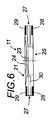
- 排出用集合体が、管状部(4)付き出口を有する反応装置に適用されることを特徴とする、前記請求項のいずれか1の請求項による排出用集合体。
- 分厚いフランジ付き出口を有する反応装置に適用されることを特徴とする、前記請求項1ないし17のいずれか1の請求項による排出用集合体。
Applications Claiming Priority (3)
| Application Number | Priority Date | Filing Date | Title |
|---|---|---|---|
| FR0701223A FR2912798B1 (fr) | 2007-02-21 | 2007-02-21 | Ensemble de vidange a ouverture vers le haut et siege plat sans zones de retention pour reacteur chimique. |
| FR07/01223 | 2007-02-21 | ||
| PCT/FR2008/000225 WO2008122710A2 (fr) | 2007-02-21 | 2008-02-21 | Ensemble de vidange a ouverture vers le haut et a siege plat sans zones de retention pour reacteur chimique emaille |
Publications (2)
| Publication Number | Publication Date |
|---|---|
| JP2010519476A true JP2010519476A (ja) | 2010-06-03 |
| JP5417661B2 JP5417661B2 (ja) | 2014-02-19 |
Family
ID=38542002
Family Applications (1)
| Application Number | Title | Priority Date | Filing Date |
|---|---|---|---|
| JP2009550303A Active JP5417661B2 (ja) | 2007-02-21 | 2008-02-21 | 上薬で被覆された化学反応装置のための貯留区域無し扁平台座付きで上方開口部を有する排出用集合体 |
Country Status (8)
| Country | Link |
|---|---|
| US (1) | US8088339B2 (ja) |
| EP (1) | EP2118537B1 (ja) |
| JP (1) | JP5417661B2 (ja) |
| CN (1) | CN101636608B (ja) |
| ES (1) | ES2633268T3 (ja) |
| FR (1) | FR2912798B1 (ja) |
| HU (1) | HUE033020T2 (ja) |
| WO (1) | WO2008122710A2 (ja) |
Cited By (2)
| Publication number | Priority date | Publication date | Assignee | Title |
|---|---|---|---|---|
| JP2015117072A (ja) * | 2013-11-18 | 2015-06-25 | 株式会社神鋼環境ソリューション | 排出弁 |
| CN104806770A (zh) * | 2015-04-15 | 2015-07-29 | 南通晨光石墨设备有限公司 | 一种石墨反应釜釜底顶底阀结构 |
Families Citing this family (4)
| Publication number | Priority date | Publication date | Assignee | Title |
|---|---|---|---|---|
| US9694732B2 (en) * | 2013-03-14 | 2017-07-04 | Marshall Excelsior Co. | Double flanged off-set valve assembly |
| DE102016000081A1 (de) * | 2016-01-07 | 2017-07-13 | Richter Chemie-Technik Gmbh | Bodenarmatur eines mobilen Tanks |
| DE102017117910A1 (de) * | 2017-08-07 | 2019-02-07 | Gemü Gebr. Müller Apparatebau Gmbh & Co. Kommanditgesellschaft | Absperrkörper für ein Fluidventil und Verfahren zur Herstellung eines Absperrkörpers |
| CN108905917A (zh) * | 2018-07-04 | 2018-11-30 | 刘伟 | 一种热能利用率高的化工反应釜 |
Citations (5)
| Publication number | Priority date | Publication date | Assignee | Title |
|---|---|---|---|---|
| JPH058141U (ja) * | 1991-07-17 | 1993-02-05 | 神鋼パンテツク株式会社 | 容器底排出弁用弁座 |
| JPH0719342A (ja) * | 1993-06-29 | 1995-01-20 | Nippon Pillar Packing Co Ltd | ガスケット |
| JPH09183487A (ja) * | 1995-12-28 | 1997-07-15 | Shinko Pantec Co Ltd | 容器用の排出弁 |
| JPH109151A (ja) * | 1996-06-26 | 1998-01-13 | Nok Corp | 逆止弁付ピストン |
| JP2002031019A (ja) * | 2000-07-19 | 2002-01-31 | Mitsubishi Motors Corp | 燃料噴射弁 |
Family Cites Families (18)
| Publication number | Priority date | Publication date | Assignee | Title |
|---|---|---|---|---|
| US860865A (en) * | 1904-09-03 | 1907-07-23 | John M Hartman | Valve-seat. |
| US2454160A (en) * | 1943-08-31 | 1948-11-16 | Pfaudler Co Inc | Corrosion resisting valve |
| US2469109A (en) | 1943-12-06 | 1949-05-03 | Pfaudler Co Inc | Noncorrodible valve |
| US3030068A (en) * | 1959-11-10 | 1962-04-17 | Hills Mccanna Co | Ball valve |
| US3177887A (en) * | 1960-10-26 | 1965-04-13 | Hills Mccanna Co | Ball valve having heat destructible seal |
| US3379410A (en) * | 1965-03-11 | 1968-04-23 | Acf Ind Inc | Valve having seat seal and venting means |
| US3380706A (en) * | 1965-06-21 | 1968-04-30 | Balon Corp | Ball valve with reinforced seals |
| IT7920556U1 (it) * | 1979-01-22 | 1980-07-22 | Tycon Spa | Terminale per sonda, per apparecchi smaltati atto a misurare la temperatura e a rilevare possibili danneggiamenti dello smalto. |
| US4359204A (en) * | 1980-11-06 | 1982-11-16 | General Motors Corporation | Rod operated valve |
| US4457491A (en) * | 1982-12-09 | 1984-07-03 | Egc Enterprises Incorp. | Extreme-temperature sealing device and annular seal therefor |
| US4649949A (en) * | 1986-03-05 | 1987-03-17 | Keystone International, Inc. | Fireproof valve assembly and seal element for use therein |
| US4822570A (en) * | 1986-12-01 | 1989-04-18 | De Dietrich (Usa), Inc. | Thermal sensing apparatus in outlet nozzle |
| US5069423A (en) * | 1990-06-21 | 1991-12-03 | The Pfaudler Companies, Inc. | Valve for clean chemical reactor |
| US7389792B2 (en) * | 1998-12-24 | 2008-06-24 | Nl Technologies, Ltd. | Dip tube valve assembly |
| US6491283B2 (en) * | 2000-03-09 | 2002-12-10 | Nl Technologies, Ltd. | Sanitary drain valve design |
| FR2812369B1 (fr) | 2000-07-28 | 2003-06-06 | Dietrich & Cie De | Siege de vanne comprenant des electrodes notamment pour dispositif de controle de type "email-test" |
| FR2820486B1 (fr) | 2001-02-02 | 2003-04-04 | Dietrich & Cie De | Organe de fermeture d'une vanne comportant un logement interieur pour une sonde permettant l'extraction de celle-ci sans demontage |
| US6664572B2 (en) * | 2001-07-23 | 2003-12-16 | Hp&T Products, Inc. | Valve seal assemblies and methods |
-
2007
- 2007-02-21 FR FR0701223A patent/FR2912798B1/fr active Active
-
2008
- 2008-02-21 ES ES08775581.5T patent/ES2633268T3/es active Active
- 2008-02-21 WO PCT/FR2008/000225 patent/WO2008122710A2/fr not_active Ceased
- 2008-02-21 EP EP08775581.5A patent/EP2118537B1/fr active Active
- 2008-02-21 CN CN2008800083793A patent/CN101636608B/zh active Active
- 2008-02-21 US US12/528,003 patent/US8088339B2/en active Active
- 2008-02-21 HU HUE08775581A patent/HUE033020T2/en unknown
- 2008-02-21 JP JP2009550303A patent/JP5417661B2/ja active Active
Patent Citations (5)
| Publication number | Priority date | Publication date | Assignee | Title |
|---|---|---|---|---|
| JPH058141U (ja) * | 1991-07-17 | 1993-02-05 | 神鋼パンテツク株式会社 | 容器底排出弁用弁座 |
| JPH0719342A (ja) * | 1993-06-29 | 1995-01-20 | Nippon Pillar Packing Co Ltd | ガスケット |
| JPH09183487A (ja) * | 1995-12-28 | 1997-07-15 | Shinko Pantec Co Ltd | 容器用の排出弁 |
| JPH109151A (ja) * | 1996-06-26 | 1998-01-13 | Nok Corp | 逆止弁付ピストン |
| JP2002031019A (ja) * | 2000-07-19 | 2002-01-31 | Mitsubishi Motors Corp | 燃料噴射弁 |
Cited By (2)
| Publication number | Priority date | Publication date | Assignee | Title |
|---|---|---|---|---|
| JP2015117072A (ja) * | 2013-11-18 | 2015-06-25 | 株式会社神鋼環境ソリューション | 排出弁 |
| CN104806770A (zh) * | 2015-04-15 | 2015-07-29 | 南通晨光石墨设备有限公司 | 一种石墨反应釜釜底顶底阀结构 |
Also Published As
| Publication number | Publication date |
|---|---|
| HUE033020T2 (en) | 2017-11-28 |
| WO2008122710A8 (fr) | 2009-09-03 |
| CN101636608A (zh) | 2010-01-27 |
| US20100166617A1 (en) | 2010-07-01 |
| CN101636608B (zh) | 2011-07-27 |
| US8088339B2 (en) | 2012-01-03 |
| ES2633268T3 (es) | 2017-09-20 |
| JP5417661B2 (ja) | 2014-02-19 |
| FR2912798A1 (fr) | 2008-08-22 |
| EP2118537B1 (fr) | 2017-06-28 |
| EP2118537A2 (fr) | 2009-11-18 |
| FR2912798B1 (fr) | 2012-12-21 |
| WO2008122710A3 (fr) | 2009-01-29 |
| WO2008122710A2 (fr) | 2008-10-16 |
| WO2008122710A4 (fr) | 2009-03-19 |
Similar Documents
| Publication | Publication Date | Title |
|---|---|---|
| JP5417661B2 (ja) | 上薬で被覆された化学反応装置のための貯留区域無し扁平台座付きで上方開口部を有する排出用集合体 | |
| EP1265696B1 (en) | Plural conduit replaceable outer support structure for radial flow system | |
| RU2004122085A (ru) | Клапан для аэрозольного порошка | |
| WO2003021139B1 (en) | Pressure-activated flexible valve | |
| KR20010071438A (ko) | 에어로졸 분말 밸브 | |
| RU2003132170A (ru) | Бутылочная крышка с однонаправленным вентилем | |
| MY136246A (en) | Apparatus for mixing, drying and coating pulverulent, granular or shaped loose material in a fluidized bed and method of producing supported catalysts using such an apparatus | |
| KR960706435A (ko) | 부정 조작 방지 스트립을 구비한 스냅식 플라스틱 뚜껑 및 그 제조 방법(plastic snap closure with a warranty seal and method for its production) | |
| US5289938A (en) | Rim structure for metal container | |
| US6427881B1 (en) | Edge seal closure | |
| RU2416557C2 (ru) | Устройство укупорочного средства для банок | |
| JPS59500961A (ja) | 容器蓋 | |
| JP2022529851A (ja) | 補助蓋を備える調理容器用蓋 | |
| US11426023B2 (en) | Beverage brewing apparatus | |
| EA016756B1 (ru) | Закрывающее устройство для бутылок и, в частности, для бутылок с алкогольными напитками или со спиртосодержащими жидкостями, обеспечивающее очевидность несанкционированного открытия бутылки | |
| RU2007121747A (ru) | Укупорочное приспособление для консервной банки | |
| RU2005135874A (ru) | Разливочная крышка | |
| US4415095A (en) | Lid and seal for jar | |
| ITMI940895A1 (it) | Camera di filtrazione con sistema di bloccaggio rapido e senza tiranteria di settori filtranti | |
| JPH0675062A (ja) | 時計装置 | |
| JP2010036908A (ja) | キャップ | |
| JP2015117072A (ja) | 排出弁 | |
| RU2529013C2 (ru) | Закрывающее устройство, содержащее источник света | |
| JP7509418B2 (ja) | 粉体充填装置 | |
| US831271A (en) | Closure device for jars, bottles, and similar vessels. |
Legal Events
| Date | Code | Title | Description |
|---|---|---|---|
| A621 | Written request for application examination |
Free format text: JAPANESE INTERMEDIATE CODE: A621 Effective date: 20101217 |
|
| A521 | Request for written amendment filed |
Free format text: JAPANESE INTERMEDIATE CODE: A523 Effective date: 20111213 |
|
| A977 | Report on retrieval |
Free format text: JAPANESE INTERMEDIATE CODE: A971007 Effective date: 20120809 |
|
| A131 | Notification of reasons for refusal |
Free format text: JAPANESE INTERMEDIATE CODE: A131 Effective date: 20120821 |
|
| A601 | Written request for extension of time |
Free format text: JAPANESE INTERMEDIATE CODE: A601 Effective date: 20121120 |
|
| A602 | Written permission of extension of time |
Free format text: JAPANESE INTERMEDIATE CODE: A602 Effective date: 20121128 |
|
| A601 | Written request for extension of time |
Free format text: JAPANESE INTERMEDIATE CODE: A601 Effective date: 20121220 |
|
| A602 | Written permission of extension of time |
Free format text: JAPANESE INTERMEDIATE CODE: A602 Effective date: 20121228 |
|
| A601 | Written request for extension of time |
Free format text: JAPANESE INTERMEDIATE CODE: A601 Effective date: 20130121 |
|
| A602 | Written permission of extension of time |
Free format text: JAPANESE INTERMEDIATE CODE: A602 Effective date: 20130131 |
|
| A521 | Request for written amendment filed |
Free format text: JAPANESE INTERMEDIATE CODE: A523 Effective date: 20130219 |
|
| TRDD | Decision of grant or rejection written | ||
| A01 | Written decision to grant a patent or to grant a registration (utility model) |
Free format text: JAPANESE INTERMEDIATE CODE: A01 Effective date: 20130903 |
|
| A61 | First payment of annual fees (during grant procedure) |
Free format text: JAPANESE INTERMEDIATE CODE: A61 Effective date: 20130926 |
|
| A61 | First payment of annual fees (during grant procedure) |
Free format text: JAPANESE INTERMEDIATE CODE: A61 Effective date: 20131101 |
|
| R150 | Certificate of patent or registration of utility model |
Ref document number: 5417661 Country of ref document: JP Free format text: JAPANESE INTERMEDIATE CODE: R150 Free format text: JAPANESE INTERMEDIATE CODE: R150 |
|
| R250 | Receipt of annual fees |
Free format text: JAPANESE INTERMEDIATE CODE: R250 |
|
| R250 | Receipt of annual fees |
Free format text: JAPANESE INTERMEDIATE CODE: R250 |
|
| R250 | Receipt of annual fees |
Free format text: JAPANESE INTERMEDIATE CODE: R250 |
|
| R250 | Receipt of annual fees |
Free format text: JAPANESE INTERMEDIATE CODE: R250 |
|
| R250 | Receipt of annual fees |
Free format text: JAPANESE INTERMEDIATE CODE: R250 |
|
| R250 | Receipt of annual fees |
Free format text: JAPANESE INTERMEDIATE CODE: R250 |
|
| R250 | Receipt of annual fees |
Free format text: JAPANESE INTERMEDIATE CODE: R250 |
|
| R250 | Receipt of annual fees |
Free format text: JAPANESE INTERMEDIATE CODE: R250 |
|
| R250 | Receipt of annual fees |
Free format text: JAPANESE INTERMEDIATE CODE: R250 |
|
| R250 | Receipt of annual fees |
Free format text: JAPANESE INTERMEDIATE CODE: R250 |