JP2010519476A - A discharge assembly with a flat pedestal with no storage area and an upper opening for a chemical reactor coated with an upper drug - Google Patents
A discharge assembly with a flat pedestal with no storage area and an upper opening for a chemical reactor coated with an upper drug Download PDFInfo
- Publication number
- JP2010519476A JP2010519476A JP2009550303A JP2009550303A JP2010519476A JP 2010519476 A JP2010519476 A JP 2010519476A JP 2009550303 A JP2009550303 A JP 2009550303A JP 2009550303 A JP2009550303 A JP 2009550303A JP 2010519476 A JP2010519476 A JP 2010519476A
- Authority
- JP
- Japan
- Prior art keywords
- discharge assembly
- discharge
- conical
- assembly according
- sealing
- Prior art date
- Legal status (The legal status is an assumption and is not a legal conclusion. Google has not performed a legal analysis and makes no representation as to the accuracy of the status listed.)
- Granted
Links
Images


Classifications
-
- F—MECHANICAL ENGINEERING; LIGHTING; HEATING; WEAPONS; BLASTING
- F16—ENGINEERING ELEMENTS AND UNITS; GENERAL MEASURES FOR PRODUCING AND MAINTAINING EFFECTIVE FUNCTIONING OF MACHINES OR INSTALLATIONS; THERMAL INSULATION IN GENERAL
- F16K—VALVES; TAPS; COCKS; ACTUATING-FLOATS; DEVICES FOR VENTING OR AERATING
- F16K1/00—Lift valves or globe valves, i.e. cut-off apparatus with closure members having at least a component of their opening and closing motion perpendicular to the closing faces
- F16K1/32—Details
- F16K1/34—Cutting-off parts, e.g. valve members, seats
- F16K1/36—Valve members
- F16K1/38—Valve members of conical shape
-
- F—MECHANICAL ENGINEERING; LIGHTING; HEATING; WEAPONS; BLASTING
- F16—ENGINEERING ELEMENTS AND UNITS; GENERAL MEASURES FOR PRODUCING AND MAINTAINING EFFECTIVE FUNCTIONING OF MACHINES OR INSTALLATIONS; THERMAL INSULATION IN GENERAL
- F16K—VALVES; TAPS; COCKS; ACTUATING-FLOATS; DEVICES FOR VENTING OR AERATING
- F16K27/00—Construction of housing; Use of materials therefor
- F16K27/07—Construction of housing; Use of materials therefor of cutting-off parts of tanks, e.g. tank-cars
-
- F—MECHANICAL ENGINEERING; LIGHTING; HEATING; WEAPONS; BLASTING
- F16—ENGINEERING ELEMENTS AND UNITS; GENERAL MEASURES FOR PRODUCING AND MAINTAINING EFFECTIVE FUNCTIONING OF MACHINES OR INSTALLATIONS; THERMAL INSULATION IN GENERAL
- F16K—VALVES; TAPS; COCKS; ACTUATING-FLOATS; DEVICES FOR VENTING OR AERATING
- F16K51/00—Other details not peculiar to particular types of valves or cut-off apparatus
-
- B—PERFORMING OPERATIONS; TRANSPORTING
- B01—PHYSICAL OR CHEMICAL PROCESSES OR APPARATUS IN GENERAL
- B01J—CHEMICAL OR PHYSICAL PROCESSES, e.g. CATALYSIS OR COLLOID CHEMISTRY; THEIR RELEVANT APPARATUS
- B01J2219/00—Chemical, physical or physico-chemical processes in general; Their relevant apparatus
- B01J2219/02—Apparatus characterised by their chemically-resistant properties
- B01J2219/0204—Apparatus characterised by their chemically-resistant properties comprising coatings on the surfaces in direct contact with the reactive components
- B01J2219/0213—Apparatus characterised by their chemically-resistant properties comprising coatings on the surfaces in direct contact with the reactive components of enamel
Landscapes
- Engineering & Computer Science (AREA)
- General Engineering & Computer Science (AREA)
- Mechanical Engineering (AREA)
- Lift Valve (AREA)
- Physical Or Chemical Processes And Apparatus (AREA)
- Indication Of The Valve Opening Or Closing Status (AREA)
Abstract
【課題】とりわけ釉薬被覆型の新品または既存の化学反応装置のための上方に向かう開口部型の排出用集合体であり、
【解決手段】排出のための出口用孔部の下部に、扁平環状パッキン状の取り替え可能な台座用部材(11)が具えてあり、同部材の上方部分が、弁の頭部(10)の台座になり、完全流出用傾斜部になっている少なくとも1の切欠き部(21)を有する。本発明は、とりわけ釉薬被覆型化学反応装置の製造者と利用者に関わる。
【選択図】図1Disclosed is an upward opening-type discharge assembly for a glaze-covered new or existing chemical reactor,
A replaceable pedestal member (11) having a flat annular packing shape is provided at a lower portion of an outlet hole for discharge, and an upper portion of the member is provided on a valve head (10). It has a pedestal and has at least one notch (21) which is a complete outflow ramp. The present invention particularly relates to manufacturers and users of glaze-coated chemical reactors.
[Selection] Figure 1
Description
本発明は、特に釉薬をかけた化学反応装置のための上方開口部付き型のゲート弁を有する排出用集合体に関する。 The present invention relates to a discharge assembly having a gate valve with an upper opening, in particular for a chemical reactor with glaze applied.
本発明の特徴は、閉鎖時の密閉性および開口時の完全流出を提供するゲート弁の頭部用扁平台座を取り囲む2の平面を含むことにある。本発明は、新品と既存のいずれにも、すべての反応装置の出口に取り付けられる。 A feature of the present invention is that it includes two planes that surround a flat pedestal for the head of the gate valve that provides hermeticity when closed and full outflow when opened. The present invention is installed at the outlet of all reactors, both new and existing.
本発明が対象としている反応装置の型では、排出用集合体の弁の可動要素の頭部は、排出用集合体が開放の上方位置にあるとき、出口区間を開放するために、排出孔の排出用スペース内に嵌め込まれている。 In the type of reactor to which the present invention is directed, the head of the movable element of the valve of the discharge assembly is provided with a discharge hole in order to open the outlet section when the discharge assembly is in the open upper position. It is fitted in the discharge space.
通常、閉鎖状態では、この頭部は、例えばポリテトラフルオロエチレンのような、化学的に抵抗力のある合成物質製台座に乗っている。 Usually, in the closed state, the head rests on a chemically resistant synthetic pedestal, such as polytetrafluoroethylene.
したがって、従来の技術では、この台座は、軸受と保持用周縁肩部になっている環状基部と管状体の密閉用部材の上部に形成されている。この密閉用部材は、その上部において、密閉用集合体の可動要素の台座になり、その下部において、排出孔部の管状突出部に対する密閉用面になる。管状部は、排出孔部の排出用管部内に挿入されている。同管状部は、排出孔部の排出用管部内に挿入されている。同管状部は、排出用管部の直径に合わせてあり、その肩部によって進入停止状に保持されている。 Therefore, in the prior art, this pedestal is formed on the bearing, the annular base portion serving as the holding peripheral shoulder, and the upper portion of the tubular member sealing member. The sealing member is a pedestal for the movable element of the sealing assembly in the upper part, and a sealing surface for the tubular projecting part of the discharge hole part in the lower part. The tubular portion is inserted into the discharge tube portion of the discharge hole portion. The tubular portion is inserted into the discharge tube portion of the discharge hole portion. The tubular part is adapted to the diameter of the discharge pipe part, and is held in an entry stop state by the shoulder part.
この台座兼密閉用管状部材は、そのもう一つの面で、排出用集合体の本体のフランジ状上方縁部に対して密閉状にぴったり付いている。 This pedestal / sealing tubular member, on the other side, is tightly sealed against the upper flange-like edge of the body of the discharge assembly.
この従来の技術には、重要な欠点が幾つもある。 This conventional technique has a number of important drawbacks.
第一の欠点は、台座と排出用管部との間に位置している間隙に存在する製品の沈着に結びついている。それは、反応装置の相次ぐ2種の製品の交互使用による汚染の原因になる。事実、台座兼密閉用部材と排出用管部との嵌め合わせは完全でなく、同台座と排出孔部の排出用管部の内側側面との間のわずかな空間の中に、進行中の反応の製品が侵入するからである。 The first drawback is associated with the deposition of the product present in the gap located between the pedestal and the discharge tube. It causes contamination due to alternating use of two successive products of the reactor. In fact, the fitting between the pedestal / sealing member and the discharge pipe is not perfect, and the reaction in progress is in a small space between the pedestal and the inner side of the discharge pipe in the discharge hole. Because of the intrusion of products.
このわずかな量は、それに接することがほぼ不可能であって、清掃と消毒用製品の侵入が困難と言うよりも不可能にしているので、残留するこの液体は、2種の製品の相次ぐ2種の反応の相互汚染源になって、それは食品産業と医薬工業では望ましくないことどころか、危険でさえある。 This small amount makes it almost impossible to touch it and makes cleaning and disinfection products difficult to penetrate rather than difficult, so this remaining liquid will be a succession of 2 products. Being a source of cross-contamination of species reactions, it is even undesirable, as opposed to undesirable in the food and pharmaceutical industries.
更に、この間隙に閉じ込められている製品が結晶すれば、ゲート弁を分解するときに大きな困難をもたらして、その結果、釉薬被覆を破壊する著しい危険性がある。 Furthermore, if the product confined in this gap crystallizes, there is a great difficulty in disassembling the gate valve, with the result that there is a significant risk of destroying the glaze coating.
本発明は、この主要欠点を排除することを目的としている。 The present invention aims to eliminate this major drawback.
本発明の第一の利点は、平滑で間隙が無いことによる相互汚染の完全な欠如に関しており、清掃と消毒をする上で接触することが困難な隠れた残留量の欠如に繋がる汚染が存在しないことにある。 The first advantage of the present invention relates to the complete lack of cross-contamination due to smoothness and no gaps, and there is no contamination leading to the lack of hidden residual quantities that are difficult to contact for cleaning and disinfection. There is.
他方では、本発明による排出用集合体は、排出用管部による出口または分厚いフランジ型の出口のいずれにしても、その構造の特性に関係なく、標準化の一般規定に応える出口をもった、新新品と既存のいずれにも、流通しているどの型の反応装置にも取りつかれる。 On the other hand, the discharge assembly according to the present invention has a new outlet that meets the general standard of standardization, regardless of the characteristics of its structure, whether it is the outlet of the discharge pipe or the outlet of the thick flange type. It can be attached to any type of reactor, whether new or existing.
下方の機械的集合体内で、台座を完全な流出と弁の可動要素に応じて取り替えるだけであり、台座が完全な流出式であるので、それによって貯留区域が無くなって、それに関連する問題と結果、とりわけ汚染および/または分解を困難にし、釉薬の破壊の明らかな危険をもたらす製品の結晶化に繋がる問題と結果が排除される。 Within the lower mechanical assembly, only the pedestal is replaced in response to complete spills and moving elements of the valve, and because the pedestal is fully spillable, it eliminates the storage area and its associated problems and consequences In particular, problems and consequences leading to crystallization of the product, which make contamination and / or degradation difficult and poses a clear risk of glaze destruction, are eliminated.
更に、そしてもちろん、本発明は、この排出用集合体を新品の反応装置に取り付けられる。対応する弁の頭部の形状に適応する密閉用台座を予定するだけで済む。 Furthermore, and of course, the present invention attaches this discharge assembly to a new reactor. All you need to do is schedule a sealing pedestal that adapts to the shape of the corresponding valve head.
要約すると、本発明は、完全な流出、死角区域の欠如、清掃と分解の容易さおよびとりわけ釉薬付きのどのような型の反応装置にも取り付けられる累積利点を提供する。 In summary, the present invention provides complete spills, lack of blind spot areas, ease of cleaning and disassembly, and cumulative benefits that can be attached to any type of reactor, particularly with glaze.
本発明のその他の特性と利点は、添付図を参照しながらなされている記述である、以後の詳細な記述を読むことによって明らかになるだろう。 Other features and advantages of the present invention will become apparent upon reading the following detailed description, which is a description made with reference to the accompanying drawings.
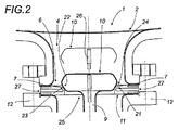
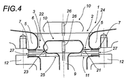
化学反応装置、とりわけ釉薬被覆型化学反応装置は、排出用すなわち空にするための孔部2を有する底部1を含んでおり、同排出孔部は、下方に向かって排出用円筒形導管3(図1)が続いており、同導管は、長い場合、排出用管状部4(図2と図3)、もっと短い場合、分厚いフランジの導管5(図4と図5)と呼ばれており、排出用管状部の前額面または分厚いフランジ5の前額面であり得る前額面7を形成している環状折り返し部で画定されている出口の外方孔部6で、外方に向かって口を開けている。
The chemical reaction device, in particular the glaze-coated chemical reaction device, includes a
便宜上、今後、この折り返し部4またはこの分厚いフランジ5の端部を出口の孔構造体と呼ぶことにする。
For convenience, the folded
出口の外方孔部6は、ロッド9と頭部10からなっている可動弁8で塞がっている。
The outlet
台座兼完全流出用取り外し可能部材11は、前額面7に密閉のために当てはめてあり、管状部4状変形態様または分厚いフランジの導管5状変形態様に当たる同出口を画定するが、後ほどみられるように、機械的取付け、次いで締めつけによって出口の外方孔部6にぴったり付く。
A pedestal and full outlet
取り替え可能な部材11は、図示の実施態様では、密閉および弁の頭部10の台座、そして製品の完全流出に役立っている、分厚いことが好ましい扁平な環状パッキンである。同部材11は、化学的に不活性で抵抗力のある、例えばPTFEの略号で知られているポリテトラフルオロエチレン製である。
The
例えば一般的な取り付け用フランジの形状の支承用部材12は、台座11を、例えばボルト付き機械的取付け用部材を介して締めつけるために、出口の環状折り返し部の前額面7との間にサンドイッチ状に挟み付け、それによって固定と押さえつけを行なって、外部に対する密閉性が得られる。
For example, a
支承用部材12はまた、排出用集合体の機械本体13の固定も、できるようにしている。支承用部材12は、この機械本体13の一部をなしており、その中に排出用集合体が嵌合されている。同集合体は、側方主出口15を有する排出室14、そして場合によっては技術用側方接触部16、ならびに下方に、パッキン箱18を具えたゲート弁のロッド9の密閉案内17を包含している。
The
弁は、下方に、機械的にいろいろな形状を呈し得る作動用装置20に続いている。図1に、開放になる高い位置と、台座に密閉状に支承することによる閉鎖の低位置間になる、弁の手動による装置を示した。
The valve is followed downwardly by an actuating
本発明は、この型の機械的集合体すなわち作動装置に限定されていない。本発明は、既存の化学反応装置の場合、単に交換用取り付けで、新規排出用集合体を取り付けることができる。 The invention is not limited to this type of mechanical assembly or actuating device. In the case of the existing chemical reaction apparatus, the present invention can attach a new discharge assembly simply by replacement installation.
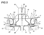
台座用部材11は、その上部に、凹部状または切欠き状の構造が配置してあり、下方で中央部に集中していて、接触すると、弁の頭部10と密閉に役立っており、および完全流出に役立っている。
The
この切欠きは、例えば円錐形の単純または二重傾斜部付きで、内1の傾斜部は巾が狭く、内側の縁部は密閉用であり、完全流出用のもっと巾広く、最初の傾斜部を同心円的に囲んでいる。この2の傾斜部の傾斜度が異なっており、内側の縁部の傾斜部は中庸であり、もう一つの傾斜部はもっとゆるい。 This notch has, for example, a conical simple or double bevel, one of the bevels is narrow, the inner edge is for sealing, wider for full spill, the first bevel Are concentrically enclosed. The slopes of the two slopes are different, the slope of the inner edge is moderate and the other slope is more loose.
この実例では、円錐形の切欠き21を指しており、その一部は、弁の頭部10がその基部に有する、対応する支承用円錐形表面と共働して、台座用部材11の円錐形受容用面21の対応する部分上において、閉鎖状態で密閉を行なう。
In this example, a
もっと特別に、円錐形切欠き面21は、まず、密閉のために、弁の頭部10の対応する支承用円錐形表面22と共働する円錐形肩部23で、外方に向かって中央部から形成されている同心円の円錐形二重傾斜部になる切欠き部である。その次に、製品の完全流出を可能にする、肩部よりもゆるい傾斜を有する円錐形傾斜部24のことを指す。この傾斜部は、肩部23の周縁から始まっており、そして例えば出口の孔部6の内方周縁部の近く、または周縁部まで延びている。
More particularly, the conical cut-
もちろん、円錐形切欠き部21に合わせてある部材11は、製品の排出用通路としての円形中央開口部を画定している。
Of course, the
ここで、円錐形切欠き部21が、開口部25と同心円で、単なる傾斜部であり得ることをはっきりさせることが妥当だろう。
Here, it will be appropriate to clarify that the conical cut-out 21 may be a concentric circle with the
部材11は、もっぱら扁平で分厚く、従来の技術のような中央部に延長部を全然有しない。
The
この後で見られるように、変形態様によっては保護用縁部が存在し得る。 As will be seen later, there may be protective edges in some variations.
反応装置のいろいろな型の出口における本発明の多数の適用の可能性を示すために、図1から図5までに、既存の化学反応装置の出口の構造の2の主要型を示した。すなわち、典型的管状部を有する反応装置の出口および分厚いフランジ5を有する出口である。
In order to show the potential for numerous applications of the present invention at different types of reactor outlets, FIGS. 1-5 show two main types of existing chemical reactor outlet structures. That is, the outlet of a reactor having a typical tubular section and the outlet having a
1の場合では、排出用管状部を形成している管路4は、比較的長いが、もう一つの場合では、明らかにもっと短い。分厚いフランジ5の変形態様であるからである。
In one case, the
1の変形態様では、弁の頭部10が反応装置の管状部内でできるだけ多くの場所を占めるように、同頭部をもっと高くする。そのために、上方端部の表面は、閉鎖状態では、反応装置の底部1と同一レベルに達する。
In one variant, the
例えば温度センサー26が、弁の頭部10の中、好ましいことにその上方端部の近くに配置してある。同センサーは、下方に淀んでいる量および排出用孔部のレベルにおける製品の温度だけに限らず、反応装置の底部1のレベルにおける温度を知ることができる。
For example, a
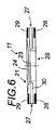
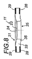
図6から図13までは、台座の部材11のいろいろな変形態様を示している。
6 to 13 show various modifications of the
どの変形態様も、開口部25のように、排出時に、製品の通行と完全流出のための円形中央開口部を有する。
All variants have a circular central opening, like the
それは、化学的に抵抗力のある半硬質の扁平環状部材11のことであり、同部材は、例えば、より密度の高い下方と上方の環状区域、あるいは付け加え、または同時押出した弾力性のより低い物質製の区域の各主要面のそれぞれに、強化された周縁を有する。この諸環状区域は、変形態様に応じて、多かれ少なかれ厚さが異なる。同諸環状区域は、反応装置の出口のフランジの前額面7、または反応装置の出口の外方孔部6を縁取る周縁折り返し部と支承用部材12で、担持面になることによって、組込みパッキンになる。環状部材11からなる扁平パッキンを締めつけるこの2のフランジの締めつけ取り付けによる機械的拘束は、同部材の固定と密閉性を保証することを可能にしている。
It is a chemically resistant semi-rigid flat
この担持面は、例えば金属製の外方環状骨組み27の形であり得る。台座用部材の上面と下面の周縁に具えた、組込みまたは取り替え可能な2の扁平パッキン28と29であり得る。
This bearing surface may be in the form of a metal outer
諸変形態様のそれぞれは、その上面に形成してある円錐形凹部21を有しており、同凹部の円錐形肩部23状中央下方部は、弁の密閉のため台座の役割をする。この中央部は、完全流出のために傾斜がもっとゆるい円錐形傾斜部24に取り囲まれている。
Each of the various modifications has a
この台座用部材11の内側の構造は、いろいろあり得る。
There can be various structures inside the
同部材は、いろいろな形状の環状リングの形の金属製芯部30、31を含むことができ、または図示のような環状部材32、または図8と図10の変形態様における33のように挿入材無しの中身のつまった部材であり得る。
The member can include
変形態様間に他の相違が存在している。 There are other differences between the variations.
下面は、縁の膨らみによる突出内方縁部34(図7)または35(図8)を含み得る。 The lower surface may include protruding inner edges 34 (FIG. 7) or 35 (FIG. 8) due to edge bulges.
その他の変形態様(図11と図12)は、突出していないが、37のようなのど部で画定されている下方縁部36を有する。
Other variations (FIGS. 11 and 12) have a
図13に示した最後の変形態様は、拡張されている芯部を有する台座に特に関する。同変形態様は、金属製紡炎周縁環状部38を含んでおり、同周縁環状部は、上方に向かって、拡張部になる肩状の上方縁部39で延長されている。この紡炎冠状部38は、火災の場合に、火炎に直接晒されないように、排出要素の密閉性を維持する時間を延ばすことを目的としている。この金属製冠状部は、例えば上方縁部の金属製周縁帯の形で具体化されており、他のどの変形態様にも存在できる。
The last variant shown in FIG. 13 is particularly concerned with a pedestal having an expanded core. The deformation mode includes a metal flame peripheral
この扁平パッキンは、例えば芯部41を有する環状体40状を呈する。
The flat packing has an
1. 反応装置の底部1
2. 孔部2
3. 排出用円筒形導管3
4. 排出用管状部4
5. 分厚いフランジの導管5
6. 出口の外方孔部6
7. 前額面7
8. 可動弁8
9. ロッド9
10. 頭部10
11. 台座11
12. 支承用部材12
13. 機械本体13
14. 排出室14
15. 側方主出口15
16. 技術用側方接触部16
17. 密閉案内17
18. パッキン箱18
19
20. 作動用装置20
21. 円錐形受容用面21
22. 支承用円錐形表面22
23. 円錐形肩部23
24. 円錐形傾斜部24
25. 開口部25
26. 温度センサー26
27. 外方環状骨組み27
28. 扁平パッキン28と29
29. 扁平パッキン
30. 金属製芯部30、31
31. 金属製芯部
32. 環状部材32
33. 中身のつまった部材33
34. 突出内方縁部34
35. 突出内方縁部35
36. 下方縁部36
37. のど部37
38. 紡炎冠状部38
39. 上方縁部39
40. 環状体40
41. 芯部41
1. Bottom of
2.
3.
4. Tubular section for
5. Thick
6.
7.
8.
9. Rod 9
10.
11.
12. Bearing
13.
14.
15. Side
16.
17. Sealing
18.
19
20.
21. Conical receiving
22.
23.
24.
25.
26.
27.
28. Flat packing 28 and 29
29.
31.
33.
34. Protruding
35. Protruding
36.
37.
38.
39.
40.
41.
Claims (19)
Applications Claiming Priority (3)
| Application Number | Priority Date | Filing Date | Title |
|---|---|---|---|
| FR07/01223 | 2007-02-21 | ||
| FR0701223A FR2912798B1 (en) | 2007-02-21 | 2007-02-21 | DRAIN ASSEMBLY WITH OPENING UP AND FLAT SEAT WITHOUT RETENTION AREAS FOR A CHEMICAL REACTOR. |
| PCT/FR2008/000225 WO2008122710A2 (en) | 2007-02-21 | 2008-02-21 | Drainage assembly with upward opening and flat seat without retention areas for enamelled chemical reactor |
Publications (2)
| Publication Number | Publication Date |
|---|---|
| JP2010519476A true JP2010519476A (en) | 2010-06-03 |
| JP5417661B2 JP5417661B2 (en) | 2014-02-19 |
Family
ID=38542002
Family Applications (1)
| Application Number | Title | Priority Date | Filing Date |
|---|---|---|---|
| JP2009550303A Active JP5417661B2 (en) | 2007-02-21 | 2008-02-21 | A discharge assembly with a flat pedestal with no storage area and an upper opening for a chemical reactor coated with an upper drug |
Country Status (8)
| Country | Link |
|---|---|
| US (1) | US8088339B2 (en) |
| EP (1) | EP2118537B1 (en) |
| JP (1) | JP5417661B2 (en) |
| CN (1) | CN101636608B (en) |
| ES (1) | ES2633268T3 (en) |
| FR (1) | FR2912798B1 (en) |
| HU (1) | HUE033020T2 (en) |
| WO (1) | WO2008122710A2 (en) |
Cited By (2)
| Publication number | Priority date | Publication date | Assignee | Title |
|---|---|---|---|---|
| JP2015117072A (en) * | 2013-11-18 | 2015-06-25 | 株式会社神鋼環境ソリューション | Discharge valve |
| CN104806770A (en) * | 2015-04-15 | 2015-07-29 | 南通晨光石墨设备有限公司 | Kettle bottom top bottom valve structure of graphite reaction kettle |
Families Citing this family (4)
| Publication number | Priority date | Publication date | Assignee | Title |
|---|---|---|---|---|
| US9694732B2 (en) * | 2013-03-14 | 2017-07-04 | Marshall Excelsior Co. | Double flanged off-set valve assembly |
| DE102016000081A1 (en) * | 2016-01-07 | 2017-07-13 | Richter Chemie-Technik Gmbh | Bottom fitting of a mobile tank |
| DE102017117910A1 (en) | 2017-08-07 | 2019-02-07 | Gemü Gebr. Müller Apparatebau Gmbh & Co. Kommanditgesellschaft | Shut-off body for a fluid valve and method for producing a shut-off body |
| CN108905917A (en) * | 2018-07-04 | 2018-11-30 | 刘伟 | A kind of chemical reaction kettle that heat utilization rate is high |
Citations (5)
| Publication number | Priority date | Publication date | Assignee | Title |
|---|---|---|---|---|
| JPH058141U (en) * | 1991-07-17 | 1993-02-05 | 神鋼パンテツク株式会社 | Valve seat for container bottom discharge valve |
| JPH0719342A (en) * | 1993-06-29 | 1995-01-20 | Nippon Pillar Packing Co Ltd | Gasket |
| JPH09183487A (en) * | 1995-12-28 | 1997-07-15 | Shinko Pantec Co Ltd | Discharge valve for container |
| JPH109151A (en) * | 1996-06-26 | 1998-01-13 | Nok Corp | Piston equipped with check valve |
| JP2002031019A (en) * | 2000-07-19 | 2002-01-31 | Mitsubishi Motors Corp | Fuel injection valve |
Family Cites Families (18)
| Publication number | Priority date | Publication date | Assignee | Title |
|---|---|---|---|---|
| US860865A (en) * | 1904-09-03 | 1907-07-23 | John M Hartman | Valve-seat. |
| US2454160A (en) * | 1943-08-31 | 1948-11-16 | Pfaudler Co Inc | Corrosion resisting valve |
| US2469109A (en) | 1943-12-06 | 1949-05-03 | Pfaudler Co Inc | Noncorrodible valve |
| US3030068A (en) * | 1959-11-10 | 1962-04-17 | Hills Mccanna Co | Ball valve |
| US3177887A (en) * | 1960-10-26 | 1965-04-13 | Hills Mccanna Co | Ball valve having heat destructible seal |
| US3379410A (en) * | 1965-03-11 | 1968-04-23 | Acf Ind Inc | Valve having seat seal and venting means |
| US3380706A (en) * | 1965-06-21 | 1968-04-30 | Balon Corp | Ball valve with reinforced seals |
| IT7920556U1 (en) | 1979-01-22 | 1980-07-22 | Tycon Spa | PROBE TERMINAL, FOR ENAMELED APPLIANCES, SUITABLE FOR MEASURING TEMPERATURE AND DETECTING POSSIBLE DAMAGE TO THE ENAMEL. |
| US4359204A (en) * | 1980-11-06 | 1982-11-16 | General Motors Corporation | Rod operated valve |
| US4457491A (en) * | 1982-12-09 | 1984-07-03 | Egc Enterprises Incorp. | Extreme-temperature sealing device and annular seal therefor |
| US4649949A (en) * | 1986-03-05 | 1987-03-17 | Keystone International, Inc. | Fireproof valve assembly and seal element for use therein |
| US4822570A (en) * | 1986-12-01 | 1989-04-18 | De Dietrich (Usa), Inc. | Thermal sensing apparatus in outlet nozzle |
| US5069423A (en) | 1990-06-21 | 1991-12-03 | The Pfaudler Companies, Inc. | Valve for clean chemical reactor |
| US7389792B2 (en) * | 1998-12-24 | 2008-06-24 | Nl Technologies, Ltd. | Dip tube valve assembly |
| JP2004519630A (en) * | 2000-03-09 | 2004-07-02 | エヌエル テクノロジーズ リミテッド | Hygienic drain valve design |
| FR2812369B1 (en) | 2000-07-28 | 2003-06-06 | Dietrich & Cie De | VALVE SEAT COMPRISING ELECTRODES IN PARTICULAR FOR AN "EMAIL-TEST" TYPE CONTROL DEVICE |
| FR2820486B1 (en) | 2001-02-02 | 2003-04-04 | Dietrich & Cie De | CLOSING BODY OF A VALVE CONTAINING AN INTERNAL HOUSING FOR A SENSOR ALLOWING THE EXTRACTION OF THE SAME WITHOUT DISMANTLING |
| US6664572B2 (en) * | 2001-07-23 | 2003-12-16 | Hp&T Products, Inc. | Valve seal assemblies and methods |
-
2007
- 2007-02-21 FR FR0701223A patent/FR2912798B1/en active Active
-
2008
- 2008-02-21 CN CN2008800083793A patent/CN101636608B/en active Active
- 2008-02-21 HU HUE08775581A patent/HUE033020T2/en unknown
- 2008-02-21 ES ES08775581.5T patent/ES2633268T3/en active Active
- 2008-02-21 JP JP2009550303A patent/JP5417661B2/en active Active
- 2008-02-21 US US12/528,003 patent/US8088339B2/en active Active
- 2008-02-21 EP EP08775581.5A patent/EP2118537B1/en active Active
- 2008-02-21 WO PCT/FR2008/000225 patent/WO2008122710A2/en not_active Ceased
Patent Citations (5)
| Publication number | Priority date | Publication date | Assignee | Title |
|---|---|---|---|---|
| JPH058141U (en) * | 1991-07-17 | 1993-02-05 | 神鋼パンテツク株式会社 | Valve seat for container bottom discharge valve |
| JPH0719342A (en) * | 1993-06-29 | 1995-01-20 | Nippon Pillar Packing Co Ltd | Gasket |
| JPH09183487A (en) * | 1995-12-28 | 1997-07-15 | Shinko Pantec Co Ltd | Discharge valve for container |
| JPH109151A (en) * | 1996-06-26 | 1998-01-13 | Nok Corp | Piston equipped with check valve |
| JP2002031019A (en) * | 2000-07-19 | 2002-01-31 | Mitsubishi Motors Corp | Fuel injection valve |
Cited By (2)
| Publication number | Priority date | Publication date | Assignee | Title |
|---|---|---|---|---|
| JP2015117072A (en) * | 2013-11-18 | 2015-06-25 | 株式会社神鋼環境ソリューション | Discharge valve |
| CN104806770A (en) * | 2015-04-15 | 2015-07-29 | 南通晨光石墨设备有限公司 | Kettle bottom top bottom valve structure of graphite reaction kettle |
Also Published As
| Publication number | Publication date |
|---|---|
| FR2912798B1 (en) | 2012-12-21 |
| US8088339B2 (en) | 2012-01-03 |
| EP2118537B1 (en) | 2017-06-28 |
| WO2008122710A2 (en) | 2008-10-16 |
| CN101636608B (en) | 2011-07-27 |
| WO2008122710A3 (en) | 2009-01-29 |
| ES2633268T3 (en) | 2017-09-20 |
| EP2118537A2 (en) | 2009-11-18 |
| HUE033020T2 (en) | 2017-11-28 |
| US20100166617A1 (en) | 2010-07-01 |
| CN101636608A (en) | 2010-01-27 |
| FR2912798A1 (en) | 2008-08-22 |
| WO2008122710A8 (en) | 2009-09-03 |
| JP5417661B2 (en) | 2014-02-19 |
| WO2008122710A4 (en) | 2009-03-19 |
Similar Documents
| Publication | Publication Date | Title |
|---|---|---|
| JP5417661B2 (en) | A discharge assembly with a flat pedestal with no storage area and an upper opening for a chemical reactor coated with an upper drug | |
| EP1265696B1 (en) | Plural conduit replaceable outer support structure for radial flow system | |
| RU2004122085A (en) | AEROSOL POWDER VALVE | |
| WO2003021139B1 (en) | Pressure-activated flexible valve | |
| KR20010071438A (en) | Aerosol powder valve | |
| RU2003132170A (en) | BOTTLE COVER WITH ONE DIRECTIONAL VALVE | |
| MY136246A (en) | Apparatus for mixing, drying and coating pulverulent, granular or shaped loose material in a fluidized bed and method of producing supported catalysts using such an apparatus | |
| US6427881B1 (en) | Edge seal closure | |
| RU2416557C2 (en) | Design of closure for jars | |
| JPS59500961A (en) | container lid | |
| JP2022529851A (en) | Cooking container lid with auxiliary lid | |
| EA016756B1 (en) | Anti-tampering closing device for bottles and in particular for bottles of alcoholic drinks or spirits preventing complete reclosure of the device | |
| RU2007121747A (en) | CANNING DEVICE FOR CANNING | |
| RU2005135874A (en) | FILLING LID | |
| US4415095A (en) | Lid and seal for jar | |
| ITMI940895A1 (en) | FILTERING CHAMBER WITH QUICK LOCKING SYSTEM AND WITHOUT FILTERING SECTOR LINKAGE | |
| JP6405201B2 (en) | Discharge valve | |
| JPH0675062A (en) | Timepiece device | |
| JP2010036908A (en) | Cap | |
| RU2529013C2 (en) | Closing device containing light source | |
| JP7509418B2 (en) | Powder filling equipment | |
| US831271A (en) | Closure device for jars, bottles, and similar vessels. | |
| EP0452603A1 (en) | Device for closing pressurised vessels | |
| JP5705587B2 (en) | Container with cap | |
| JP2004291996A (en) | Cap |
Legal Events
| Date | Code | Title | Description |
|---|---|---|---|
| A621 | Written request for application examination |
Free format text: JAPANESE INTERMEDIATE CODE: A621 Effective date: 20101217 |
|
| A521 | Request for written amendment filed |
Free format text: JAPANESE INTERMEDIATE CODE: A523 Effective date: 20111213 |
|
| A977 | Report on retrieval |
Free format text: JAPANESE INTERMEDIATE CODE: A971007 Effective date: 20120809 |
|
| A131 | Notification of reasons for refusal |
Free format text: JAPANESE INTERMEDIATE CODE: A131 Effective date: 20120821 |
|
| A601 | Written request for extension of time |
Free format text: JAPANESE INTERMEDIATE CODE: A601 Effective date: 20121120 |
|
| A602 | Written permission of extension of time |
Free format text: JAPANESE INTERMEDIATE CODE: A602 Effective date: 20121128 |
|
| A601 | Written request for extension of time |
Free format text: JAPANESE INTERMEDIATE CODE: A601 Effective date: 20121220 |
|
| A602 | Written permission of extension of time |
Free format text: JAPANESE INTERMEDIATE CODE: A602 Effective date: 20121228 |
|
| A601 | Written request for extension of time |
Free format text: JAPANESE INTERMEDIATE CODE: A601 Effective date: 20130121 |
|
| A602 | Written permission of extension of time |
Free format text: JAPANESE INTERMEDIATE CODE: A602 Effective date: 20130131 |
|
| A521 | Request for written amendment filed |
Free format text: JAPANESE INTERMEDIATE CODE: A523 Effective date: 20130219 |
|
| TRDD | Decision of grant or rejection written | ||
| A01 | Written decision to grant a patent or to grant a registration (utility model) |
Free format text: JAPANESE INTERMEDIATE CODE: A01 Effective date: 20130903 |
|
| A61 | First payment of annual fees (during grant procedure) |
Free format text: JAPANESE INTERMEDIATE CODE: A61 Effective date: 20130926 |
|
| A61 | First payment of annual fees (during grant procedure) |
Free format text: JAPANESE INTERMEDIATE CODE: A61 Effective date: 20131101 |
|
| R150 | Certificate of patent or registration of utility model |
Ref document number: 5417661 Country of ref document: JP Free format text: JAPANESE INTERMEDIATE CODE: R150 Free format text: JAPANESE INTERMEDIATE CODE: R150 |
|
| R250 | Receipt of annual fees |
Free format text: JAPANESE INTERMEDIATE CODE: R250 |
|
| R250 | Receipt of annual fees |
Free format text: JAPANESE INTERMEDIATE CODE: R250 |
|
| R250 | Receipt of annual fees |
Free format text: JAPANESE INTERMEDIATE CODE: R250 |
|
| R250 | Receipt of annual fees |
Free format text: JAPANESE INTERMEDIATE CODE: R250 |
|
| R250 | Receipt of annual fees |
Free format text: JAPANESE INTERMEDIATE CODE: R250 |
|
| R250 | Receipt of annual fees |
Free format text: JAPANESE INTERMEDIATE CODE: R250 |
|
| R250 | Receipt of annual fees |
Free format text: JAPANESE INTERMEDIATE CODE: R250 |
|
| R250 | Receipt of annual fees |
Free format text: JAPANESE INTERMEDIATE CODE: R250 |
|
| R250 | Receipt of annual fees |
Free format text: JAPANESE INTERMEDIATE CODE: R250 |
|
| R250 | Receipt of annual fees |
Free format text: JAPANESE INTERMEDIATE CODE: R250 |